Article

Effect of Plasma Electrolytic Oxidation on the Short-Term Corrosion Behaviour of AZ91 Magnesium Alloy in Aggressive Chloride Environment

1
Department of Materials Engineering, Faculty of Mechanical Engineering, University of Zilina, 010 26 Zilina, Slovakia
2
Research Centre UNIZA, University of Zilina, 010 26 Zilina, Slovakia
3
Department of Physics, Faculty of Electrical Engineering and Information Technology, University of Zilina, 010 26 Zilina, Slovakia
*
Author to whom correspondence should be addressed.
Coatings 2022, 12(5), 566; https://doi.org/10.3390/coatings12050566
Submission received: 28 February 2022 / Revised: 12 April 2022 / Accepted: 15 April 2022 / Published: 21 April 2022
(This article belongs to the Special Issue Quality Tools in the Design of Coatings)

Abstract

:
In order to increase the corrosion resistance of magnesium alloy AZ91 in corrosion environments containing chlorides, the alloy surface has been modified by plasma electrolytic oxidation (PEO). The chemical composition of electrolyte in the PEO process consisted of 12 g/L Na3PO4·12 H2O and 1 g/L KOH, and a direct current was applied to the sample. The corrosion resistance of PEO coating and as-cast AZ91 (sample without PEO coating) was assessed using two different electrochemical methods: electrochemical impedance spectroscopy (EIS) and potentiodynamic polarisation (PDP) in 0.1 M NaCl at laboratory temperature. In addition to the electrochemical methods, the morphology of the oxidic coating was observed in the cross-sectional and top surface view by using the SEM technique. For better determination of the microstructure and PEO coating, chemical composition EDX analysis was used. The results of the experiments show that the formation of the PEO coating on AZ91 alloy has a more positive effect on the corrosion resistance in 0.1 M NaCl based on electrochemical methods than in the case of the formed coating on AZ31 alloy from the previous study. Based on electrochemical measurements in the selected environment, the formation of PEO coating on AZ91 was accompanied by a significant increase in polarisation resistance after short-term exposure compared to the as-cast surface. The EIS results showed a 73 times higher Rp value for PEO coated AZ91 when compared to the as-cast AZ91. Correspondingly, a 27 times lower icorr value was observed for PEO coated AZ91 than in the case of substrate AZ91 in 0.1 M NaCl. At the same time, the typically porous and inhomogeneous structure of the formed PEO coating on the magnesium alloy AZ91 was demonstrated.

1. Introduction

Magnesium is the eighth most represented element in the Earth’s crust. Due to its specific characteristics, it is an attractive alternative for use in certain industries. The useful properties of magnesium and its alloys include high electrical and thermal conductivity (e.g., in portable computers), the ability to absorb electromagnetic radiation (e.g., mobile phone covers), dimensional stability, machinability and recyclability, which allow potentially wide usage of these materials. Other benefits include high specific strength (ratio between strength and density), casting properties and an excellent damping effect, which is important in the automotive and aerospace industries [1,2]. To improve mechanical and corrosion properties, magnesium is alloyed with various additives. Commercially used alloys are based on the Mg–Al system with the addition of other alloying elements such as zinc, manganese, silicon and rare earth metals. The AZ91 alloy is the most widely used magnesium alloy, representing approximately 90% of total magnesium production [3]. The sand and permanent mold casting alloys are used for special applications. Racing wheels, engine blocks and certain parts for aircraft and helicopters constitute the majority of applications in the industry [4]. The most commonly used alloy for the automotive industry and biomedical applications among different magnesium alloy systems is AZ91 magnesium alloy, because of its relatively higher mechanical properties and better corrosion performance in aggressive aqueous solutions. Precipitates in the microstructure of AZ91 are Mg17Al12 and Al4Mn or Al8Mn5, depending on the way of solidification. The Mg17Al12 precipitates are particularly known for a better mechanical strengthening of the AZ91 alloy at the expense of its ductility [5]. The high purity alloy, for instance, AZ91E, has corrosion resistance in saltwater from 10 ± 100 times better than the conventional metal, and equal to or better than mild steel and the die cast aluminium alloy, 380 [6,7]. On the other hand, the use of magnesium and its alloys is limited to certain working environments due to their low corrosion resistance [8].
Existing investigations have clearly suggested that the corrosion behaviour of Mg alloys is very different from that of a convention metal, such as steel. For more successful applications of Mg alloys, it is important to understand their characteristic corrosion phenomena and have practical corrosion strategies for its prevention [9,10]. Magnesium alloys are prone to galvanic corrosion. One of the main reasons which is responsible for poor corrosion resistance of Mg is given by the low standard potential of pure Mg with a high negative value of −2.36 V vs. SHE (standard hydrogen electrode), which is one of the lowest among engineering metals [11,12]. A galvanic cell is formed when different metals are electrically connected in the presence of an electrolyte. Magnesium will act almost always as an anode when connecting to another metallic material in the presence of a conductive solution. A galvanic cell is formed within one material usually called micro-galvanic corrosion, which may occur between the α-Mg matrix with its surrounding second phases or intermetallic compounds (for instance, Mg17Al12) which have a nobler standard electrode potential in the microstructure than the α-Mg. The matrix is, thus, anodic and will be preferentially dissolved [13,14].
Therefore, proper surface treatment can increase both corrosion and wear resistance. In recent decades, a large number of surface treatments have been developed for magnesium and its alloys, but only a few processes have actually achieved commercial use. In the case of magnesium and its alloys, chemical conversion coatings, electrodeposition, anodizing, organic coatings, sol–gel technology, etc., are used as finishes [15]. The PEO process is an ecological and cost-effective surface treatment that is performed in the electrolyte free of toxic substances, giving the advantage over other processes, e.g., (anodizing where the work piece is immersed in the acid electrolyte). Other principal advantages of the PEO process are a raised corrosion and wear resistance simultaneously together with other characteristics, such as improved biocompatibility, biodegradability, dielectric properties and thermal stability due to the oxide coating [16]. This process can be used to grow thick (tens or hundreds of micrometres), oxidic coatings on the surface of light metals and their alloys (Al, Mg and Ti) due to local dielectric breakdown of the oxide film and formation of micro-arc discharges. In the formation of the PEO coating, the substrate of light alloys (Al, Mg and Ti) are chemically transformed into its oxide, which grow during the process simultaneously inwards and outwards from the bulk metal surface.
The quality and composition of PEO coating strongly depends on process parameters, such as electrolyte composition, the concentration of chemicals, applied current and voltage regime. Last but not least, the chemical composition of the coated material, including thermal treatment, plays an important role in the formation of the PEO coating, including its corrosion resistance [17]. Unfortunately, the discharges that are produced during the PEO process are responsible for the various non-uniformities and defects in the coating, such as discharge channels, pores from entrapped gas, and other cracks. Such defects are reasonably critical for magnesium alloys from a corrosion point of view, since they open up fast pathways for the electrolyte to reach the substrate. Therefore, all the defects affect the corrosion resistance of the coated substrate [18].
Although the PEO process is more costly in comparison to the mere chemical passivation, some PEO coated parts are used in the automotive industry for a toxic chromate replacement wherever corrosion-resistance standards are strong enough to fulfil the requirements. This includes motor sport, where it is commonly used as a magnesium coating, e.g., in Formula One [19,20]. PEO coatings significantly enhance the corrosion resistance of Mg alloys. Therefore, it is reasonable to apply the PEO process to the engine coolant channel and the cylinder bores of the Mg engine block to provide sufficient corrosion and wear protection. Nowadays, PEO coated materials are also used to treat the surface of cell phones. By customising porosity, PEO treatment can enhance the sticking properties of colour paints, sol–gel coatings, and powdered coating, which form duplex coatings possessing improved properties. Another field of application of PEO is biomedical engineering, such as the production of osseo-integrative coatings for orthopaedic and dental implants. This is mainly because the implant materials have to meet certain requirements, such as biocompatibility (hemocompatibility, cytocompatibility), non-toxicity, chemical stability and corrosion resistance [21].
The novelty of research can be found in the usage of specific optimised process parameters (chemical composition of the electrolyte and applied energy input) from our previous studies [22,23] performed on AZ31 magnesium alloy in phosphate-based electrolyte for experiments on AZ91 Mg, with the aim to increase knowledge about the effect of PEO treatment on various Mg–Al alloys. In addition, a comparison between the corrosion properties of PEO coating from other studies using identical solutions for the PEO process will be revealed.

2. Materials and Methods

Experimental work was carried out on the as-cast state of AZ91 magnesium alloy. The chemical composition of the alloy has been detected by EDXRF analysis on the apparatus ARL QUANT’X EDXRF and it is given in Table 1. SEM images, together with EDX analysis, were performed on the TESCAN LYRA3 microscope. Roughness parameters were observed on a Zeiss Optimal microscope with a confocal head LSM 700. Metallographic preparation consisted of sampling by a metallographic saw, subsequent embedding of the samples into epoxy resin, and grinding with SiC paper up to 1200 p. Subsequently, samples were polished on polishing canvases with an application of diamond paste with a graining of 3 μm and 1 μm. Samples for microstructure analysis were etched with 2% Nital for 5 s, then rinsed with demineralised water, and ethyl alcohol and dried with a stream of air. The microstructure was observed by using the Zeiss Imager microscope A1m.
Magnesium alloy AZ91 was connected as an anode (positive pole) and stainless steel as a cathode (negative pole) in a two-electrode wiring system during the PEO process. The chemical composition of the electrolyte for PEO consisted of 12 g/L Na3PO4·12 H2O and 1 g/L KOH, and its pH stabilised at 12.5. The cooling system consisted of a container with cold water surrounding the tank with electrolyte for the PEO process. The surface of the samples was treated with p1200 SiC paper prior to the PEO process in order to achieve the best possible uniformity of the surface. A constant current density of 0.05 A/cm2 was applied to the anode during 14 min of preparation of the PEO coating. At the end of the PEO process, the samples were dried with a stream of air. The scheme of the equipment for the PEO process is shown in Figure 1.
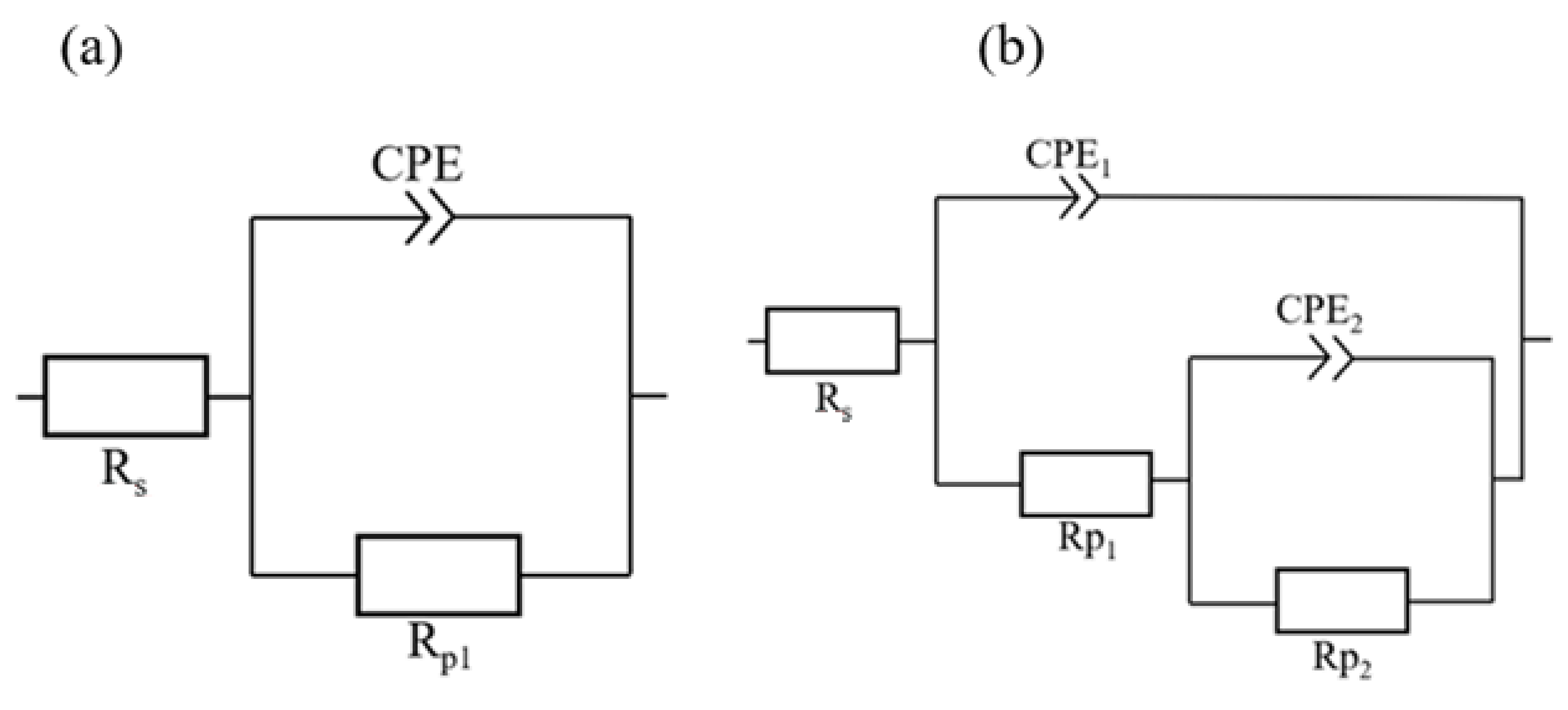
The roughness, surface morphology and cross-section of PEO coating were observed using the Zeiss AXIO Observer Z1 microscope with a confocal head LSM 700 in Zen 2.0 software. The corrosion resistance of the as-cast samples and PEO surface was assessed by measuring the electrochemical characteristics obtained from both electrochemical methods: electrochemical impedance spectroscopy (EIS) and potentiodynamic polarisation (PDP) in a solution of 0.1 M NaCl. Before each measurement, all specimens were ground on the emery papers with granularity p1200, consequently rinsed by demineralised water, and ethyl alcohol and dried with a stream of air. All measurements were carried out on the laboratory potentiostat VSP Biologic at a temperature of 22 ± 2 °C. In the three-electrode system used for electrochemical measurements, the magnesium and PEO sample was connected as a working electrode (WE), platinum electrode as a counter (CE) and saturated calomel electrode (RE) served as a reference electrode (+0.2446 V vs. SHE). The period of steadying potential between the sample and electrolyte was selected for 60 min. Potentiodynamic tests took place in the range of potentials from −200 mV to +500 mV vs. open circuit potential (OCP) and the rate of potential changing was set to 1 mV·s−1. The analysis of potentiodynamic polarisation curves was carried out using Tafel’s analysis in EC-Lab V11.10 software, from which the following electrochemical characteristics were obtained: corrosion potential Ecorr and corrosion current density icorr, from which the corrosion rate was quantified using the software. Electrochemical impedance spectroscopy was performed at the OCP value ranging from 100 kHz to 10 mHz, with the frequency changing 10 times in a decade. The amplitude of the potential signal was set to 15 mV. All measurements were repeated five times. The EIS measurement results are presented in the form of Nyquist and Bode plots diagrams [23,24,25]. The interpretation of impedance data is generally based on the use of EEC (electrical equivalent circuits). Resistance is the element Rp [23,26]. Whereas Rp1 in simple EEC represents a metal/electrolyte interface. In the case of complex EEC for PEO coated sample, Rp1 represents the porous outermost coating layer, and Rp2 represents an inner layer of PEO coating which is responsible for corrosion resistance [27]. The electrical equivalent circuit in Figure 2 describes a simple system with a sample/electrolyte interface. Element Rs represents electrolyte resistance, and the CPE element is called a constant phase element which is used to replace double-layer capacitance (Cdl). The heterogeneity of the surface, such as roughness, nonhomogeneous composition, etc., significantly affects the value of the constant phase element CPE [24].

3. Results

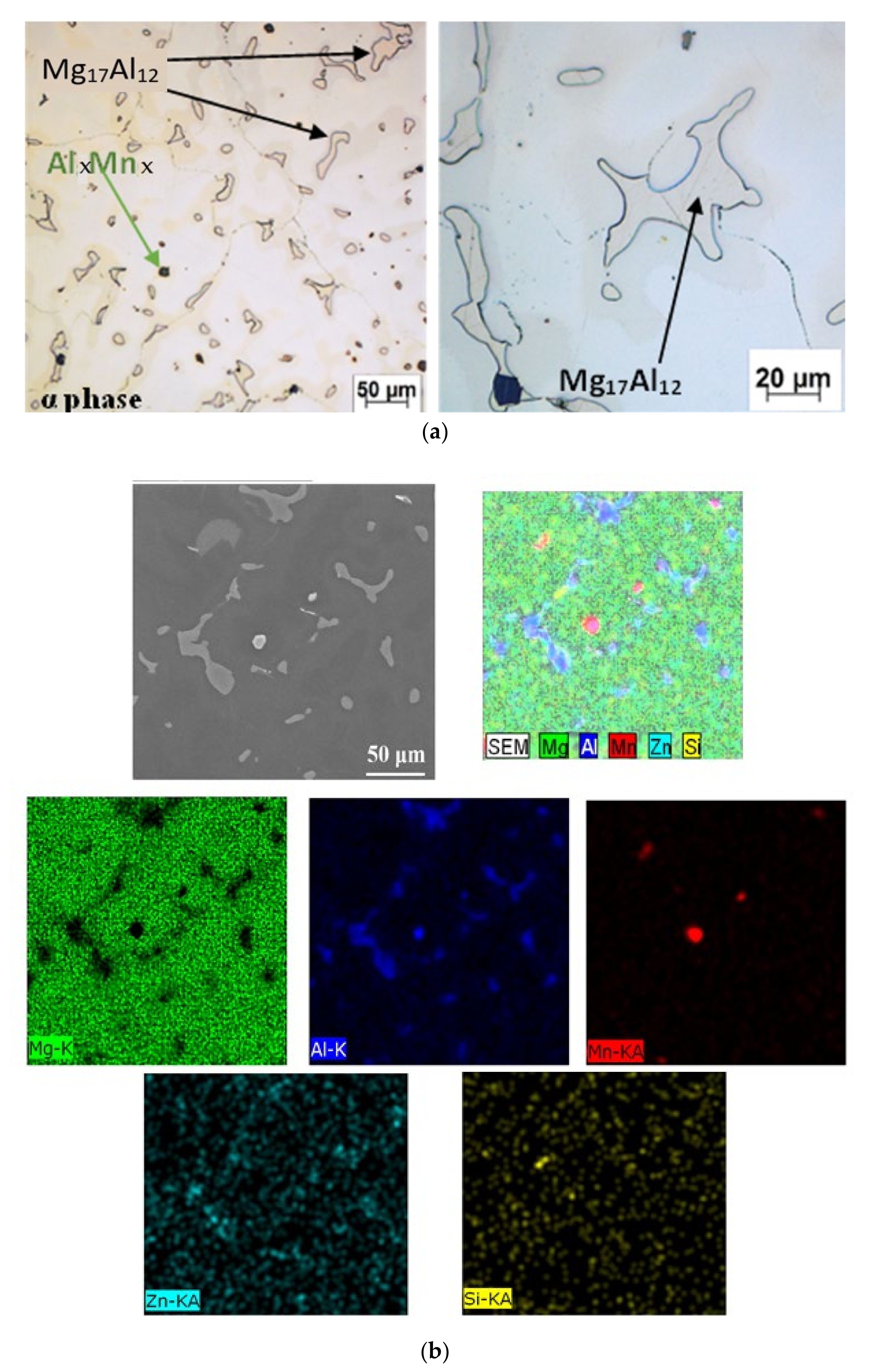
Figure 3a reveals the microstructure of AZ91 magnesium alloy. The microstructure of magnesium alloy AZ91 in the as-cast state is composed of a solid solution α together with the intermetallic compound Mg17Al12, also referred to as the β-phase. In the as-cast condition microstructure of AZ91 (Figure 3a,b), consists of an α-matrix together with intermetallic β-phase Mg17Al12. EDX analysis (Figure 3b) revealed that the aluminium content in the microstructure may be various, however around the β-phase, its content is undoubtedly higher than in the α-matrix. Zinc content is also higher around the β-phase when compared to the α-phase based on the results from EDX analysis in Figure 3b. Similar observations were found in the study [28] on the AZ91 magnesium alloy.
Furthermore, another intermetallic compound of Al–Mn type is present in the microstructure in Figure 3a,b due to the presence of Mn in the microstructure, which is added to most magnesium Mg–Al alloys [29]. Mn-based phases in the microstructure of AZ91 were reported also in the works [30]. The β-phase in the magnesium alloy microstructure AZ91 can have a double effect on corrosion resistance. According to Song et al. (1999), the β-phase serves as a cathode and increases the corrosion rate of the α-phase if its alloy share is low [31]. On the other side in the case of AZ91, a significant fraction of the β-Mg17Al12 phase is distributed along grain boundaries, which represents a cathodic area in relation to the matrix. This phase is not susceptible to corrosion attack in solutions containing chlorides and acts as a corrosion barrier for the α-Mg matrix, moreover, β-phase Mg17Al12 tends to form a passive layer on its surface, which also slows down the corrosion rate [32] Figure 3b reveals the main elements in the microstructure of AZ91, whereas it demonstrates the chemical representation of principal elements of the selected phases, including phases Mg17Al12 and Al–Mn type.
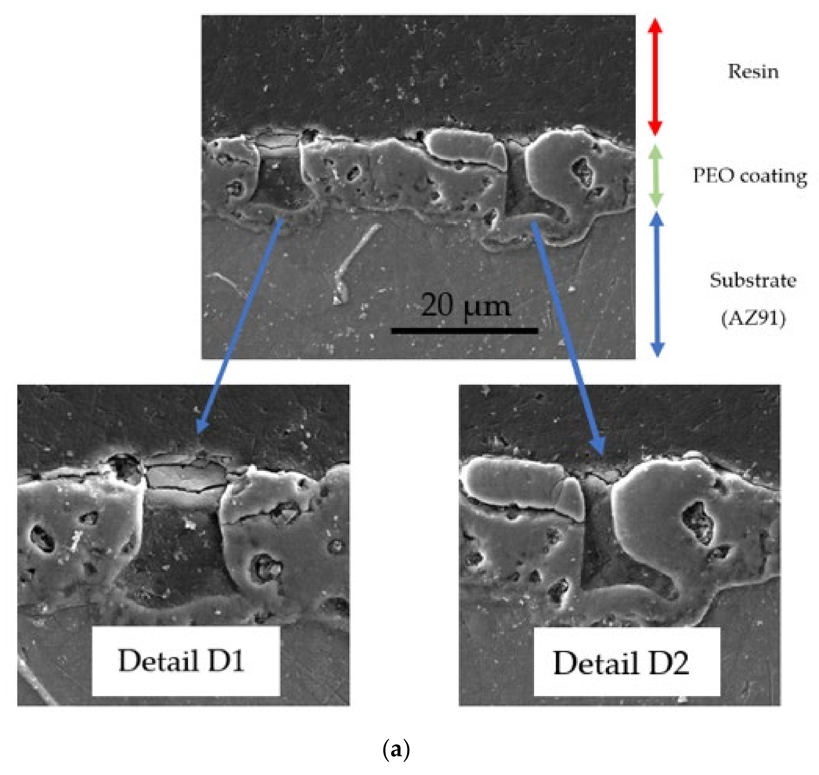
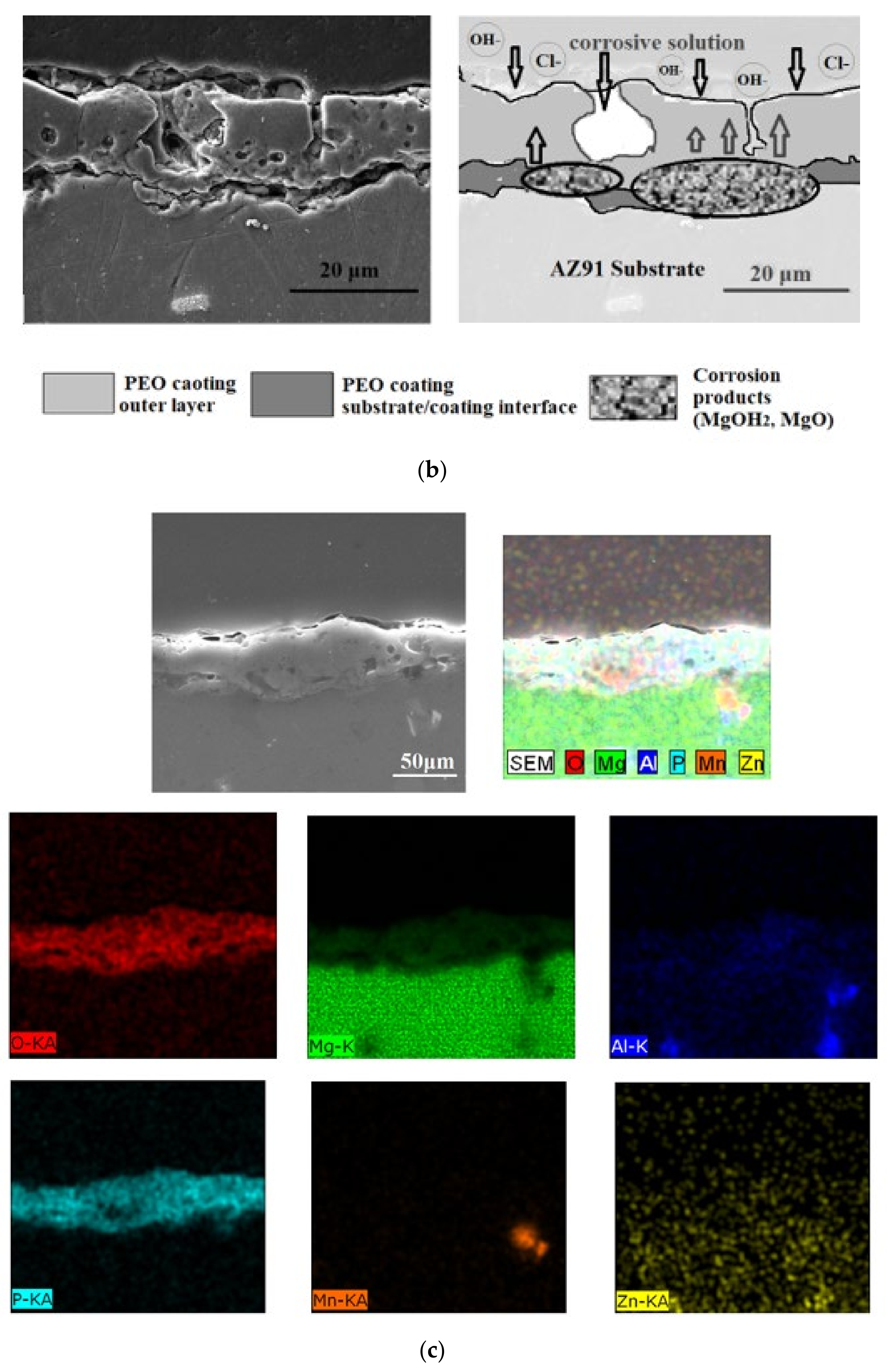
The cross-section of various SEM images of PEO coating is shown in Figure 4a–c, where the defective structure of the coating can be observed. The interfaces between substrate/coating and principal corrosion mechanism are presented in Figure 4b. Chemical composition of the main elements in the PEO coating formed in phosphate electrolyte is present in the SEM images in Figure 4c. The microstructure and morphology of prepared PEO coating depend on the different types of dischargers that occur during its formation. Research from authors Martin et al. [33] shows the presence of so-called open pores that pass through the entire cross-section of the PEO coating just near precipitates.
Figure 4b demonstrates the possible mechanism of corrosion product formation in Figure 4b (right one) for PEO coating formed in phosphate electrolytes. This mechanism of coatings degradation differs depending on the solution in which the PEO process took place. In Figure 4b (left), the interface of substrate/coating can be seen. Authors in the work [34] stated that after immersion in 0.1 M NaCl, corrosion products (magnesium hydroxide) are formed at the interface substrate/coating after the electrolyte hits the substrate, moreover, the products grow to such a level that it exerted stress that lifted/damaged the PEO coating. The lift-off of the coating in these areas resulted in the exposure of the underneath substrate to the electrolyte.
XRD analysis from the researchers in the work [34], revealed that PEO coating formed in phosphate electrolyte was constituted with Mg3(PO4)2 and MgO. This is, in fact, confirmed with the EDX analysis in Figure 4b, where the main elements in PEO coating are phosphorus, oxygen and magnesium.
Details of D1 and D2 from Figure 4 show pores that pass almost across the whole coating’s thickness. Based on the results of the works [35,36], it is stated that the average growth rate of the oxidic coating is linear in the initial minutes. The nature of discharges also depends on the chemical composition of the coated material. Around intermetallic phases, including Mg17Al12, the more intense discharges occur, which can be assumed to be the places with the largest pores. The average thickness and other roughness parameters for as-cast AZ91 and PEO coated surfaces are listed in Table 2. In addition to the abovementioned defects, there are also micro-cracks in the coating, resulting from the cooling of molten oxides in cold electrolyte, which is in agreement with the assertion of Kaseem et al. [37,38]. The average thickness of the PEO coating in this work reached an average thickness of 16 μm during the 14 min of its formation, by comparing the thickness of the PEO coating with our previous study from Hadzima et al. [22], where an average coating thickness of 9 μm has been achieved over 10 min of formation on an AZ31 alloy with the same chemical electrolyte composition for the PEO process and the same applied current density. The details of D1 and D2 represent the most significant microstructure defects that obviously reduce the integrity and local thickness of the PEO coating.
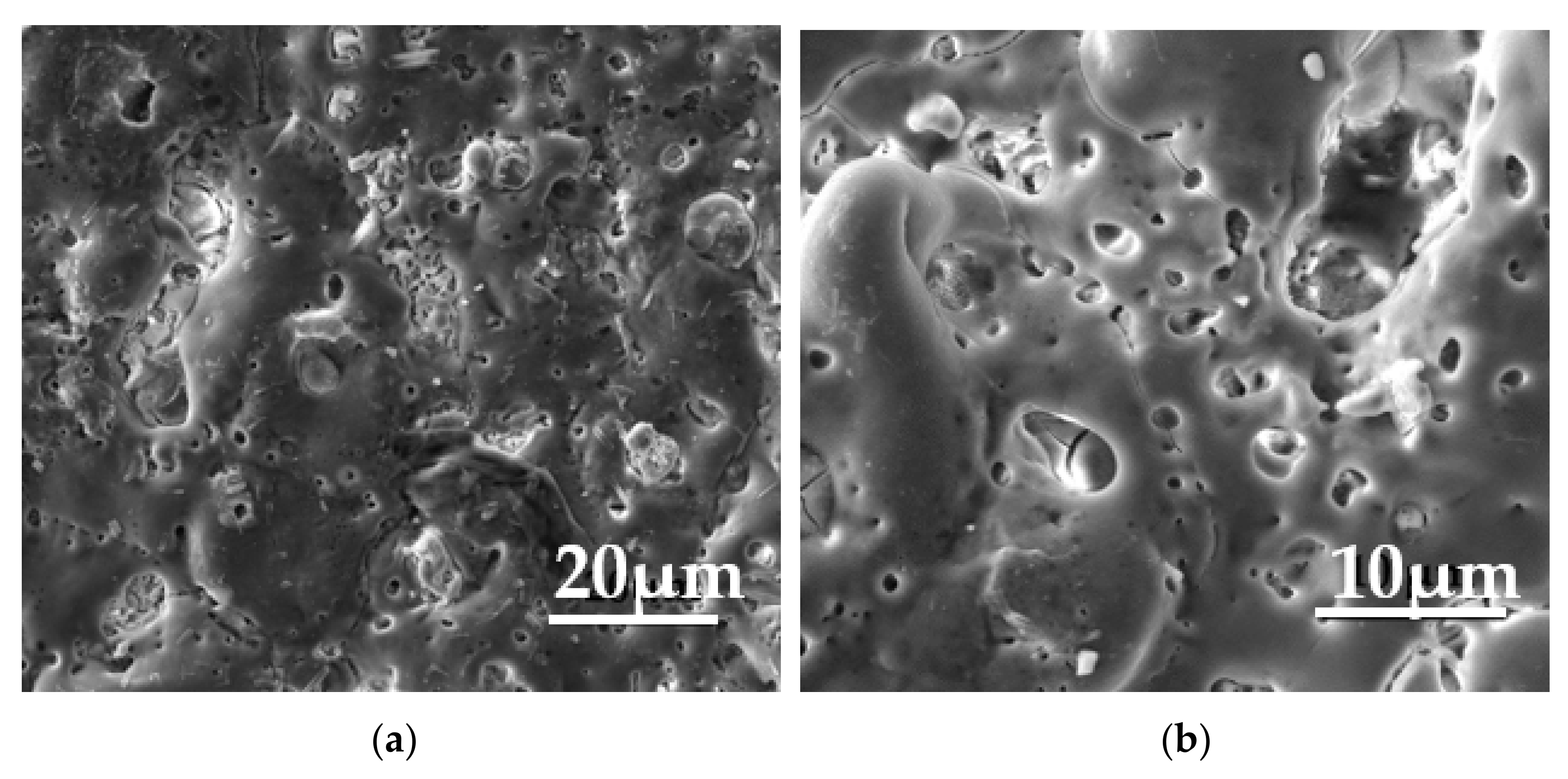
The surface morphology of the PEO coating is shown in Figure 5. It is clear that the diameter of pores is variable, with an average value of 5 μm. The size of these pores is a function of the applied current density and depends also on the time of the preparation [19,22]. The coating’s growth is described by basic electrochemical reactions (1)–(4) taking place at the metal/electrolyte interface, representing anodic dissolution of magnesium and formation of Mg(OH)2, MgO [8].
Mg → Mg2+ + 2 e
Mg2+ + 2 OH → Mg(OH)2
Mg(OH)2 → MgO + 2 H2O
3 Mg2+ + 2 PO43− → Mg3(PO4)2
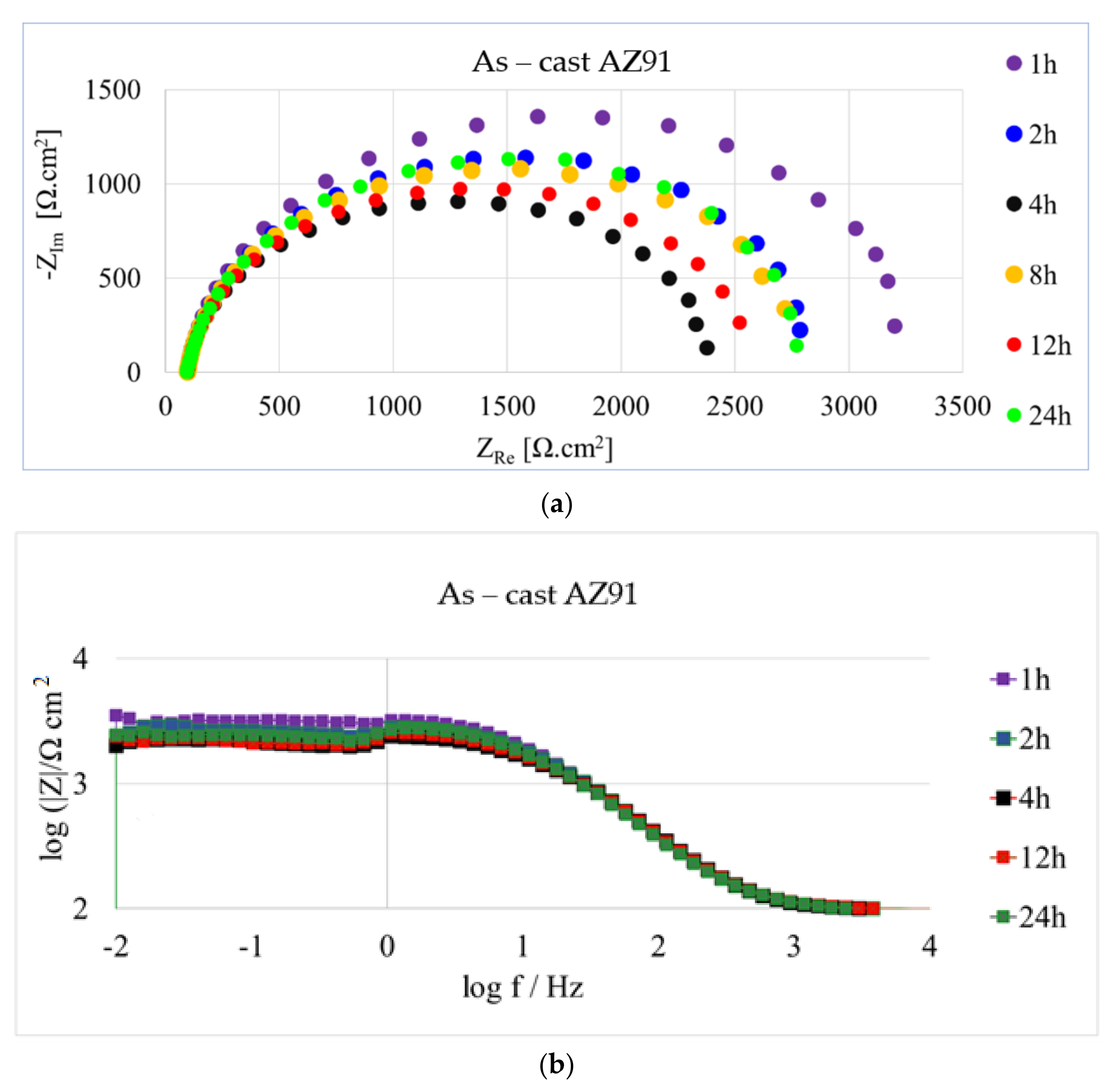
Obtained electrochemical impedance behaviour from EIS measurements for the as-cast AZ91 surface in 0.1 M NaCl is shown in Figure 6a,b in the form of Nyquist and Bode plots, respectively. Analysed electrochemical characteristics were obtained from Nyquist and Bode plots using simple EEC from Figure 2a due to the occurrence of one semicircle and are listed in Table 3. The average value of electrolyte resistance Rs was 98 Ω·cm2 without any significant change during the whole exposure. The highest value of Rp was obtained after 1 h of exposure (3278 Ω·cm2). Further evolution of Rp was characterised during the first 4 h of exposure by a gradual decrease to the value of (2337 Ω·cm2). After 12 h of exposure, Rp increased up to 2507 Ω·cm2. The last interval after 24 h was characterised by the increase in the value of Rp up to 2825 Ω·cm2. The evolution of constant phase element CPE increased from the beginning of the experiment from the lowest value of CPE, reaching 8.044 F·sn−1·10−6 after 1 h of exposure. From the overall point of view, the CPE gradually increased from the start of the experiment, reaching its highest level after 24 h of exposure, namely 9.422 F·sn−1·10−6.
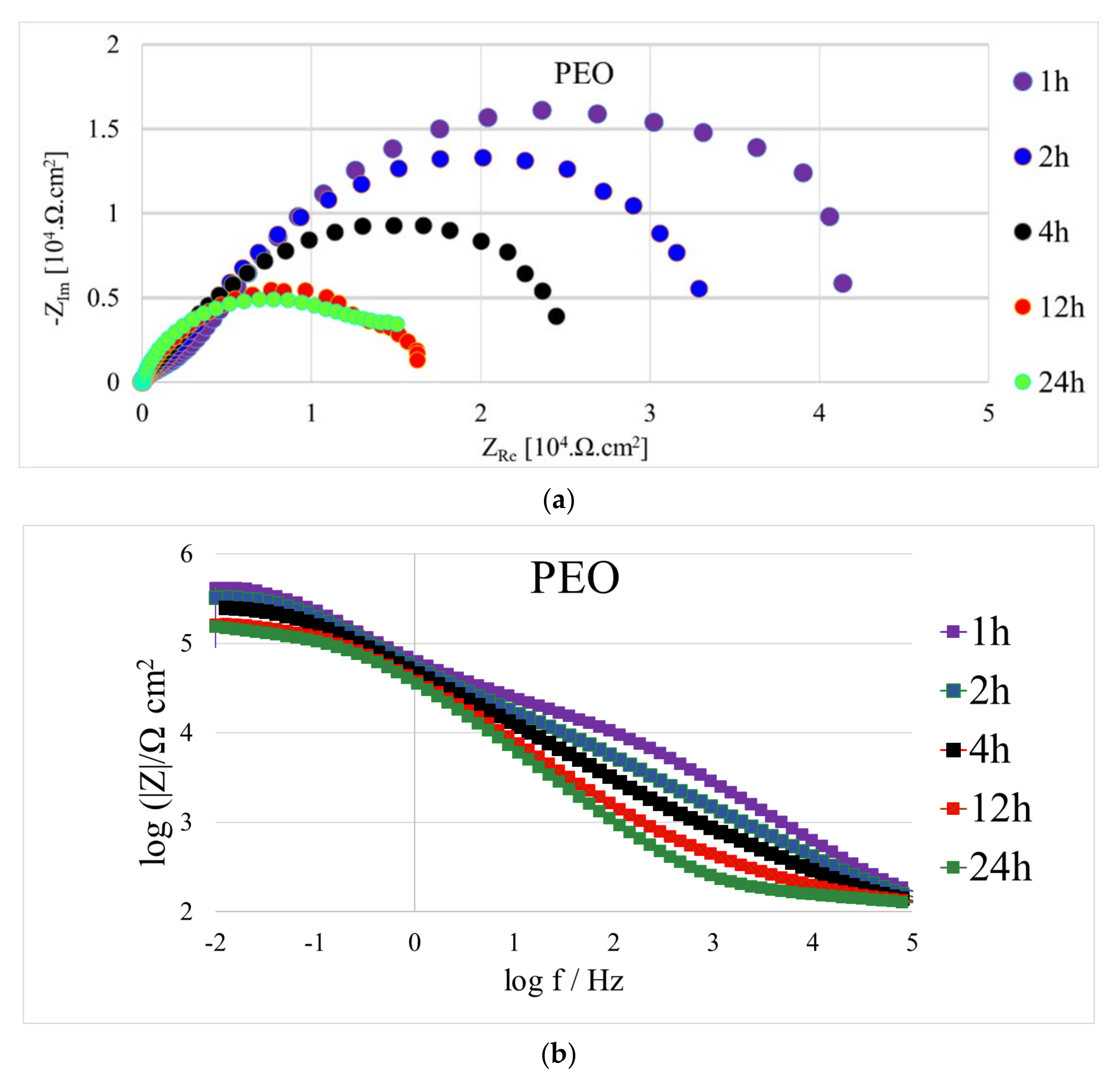
The obtained electrochemical impedance behaviour from EIS measurements for PEO coated AZ91 in 0.1 M NaCl is shown in Figure 7a,b in the form of Nyquist and Bode plots, respectively. Analysed electrochemical characteristics are listed in Table 4. The positive effect of prepared PEO coating on AZ91 magnesium alloy is significant when comparing the resulting Rp values from Table 3 and Table 4. The obtained value of Rp 429,970 Ω·cm2 after 1 h of exposure for the PEO coated surface was the highest in all experiments. This evolution was consequently followed by a decrease of around 20% from the first value or Rp. Equally, a downward trend of Rp continued until reaching the lowest value after 12 h of exposure of 191,805 Ω·cm2. However, this minimum was subsequently followed by a slight increase up to a value of 207,515 Ω·cm2 which was also the end of the experiment after 24 h exposure. Correspondingly, the evolution of CPE1 and CPE2 for PEO coated surfaces had opposite trends from the overall point of view in comparison to the evolution of Rp1 and Rp2, respectively.
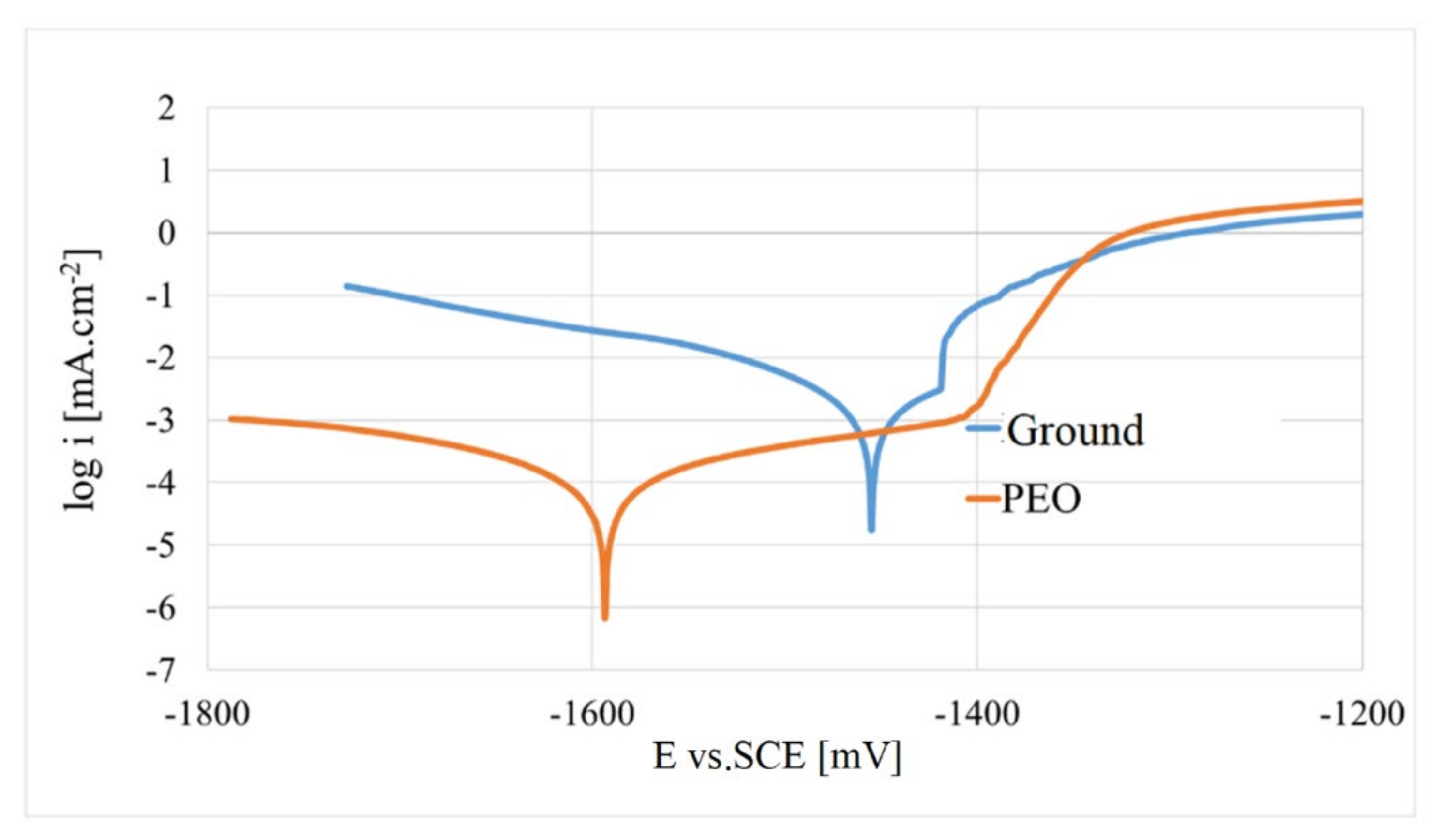
Potentiodynamic polarisation (PD) curves shown in semi-logarithmic coordinates (Figure 8) were analysed by using Tafel analysis. The electrochemical characteristics obtained from the (PD) curves, i.e., the corrosion potential Ecorr, the corrosion current density icorr and the corrosion rate rcorr, are given in Table 5. The characteristics describing thermodynamics (Ecorr) and electrochemical corrosion kinetics (icorr) have been supplemented by inclinations of the anode or cathode-like part of the polarisation curve (βa and βc) [39].
The mean value of icorr for the as-cast surface reached 3.86 μA·cm−2, in the case of PEO coating it was only 0.14 μA·cm−2, thus, significantly lower (more than 27 times) than for the as-cast surface, which is in line with the results achieved with the EIS measurements. The Ecorr value (−1465 mV) for the as-cast surface is more positive than the Ecorr value for PEO coating by 160 mV. As a result, the as-cast surface reached an almost 27 times higher value of rcorr (87.5 mm·year−1·10−3) when compared to the PEO coating. The values of both surfaces are highly electro-negative, which means that in normal environments, degradation of the surface by electrochemical corrosion will occur.

4. Discussion

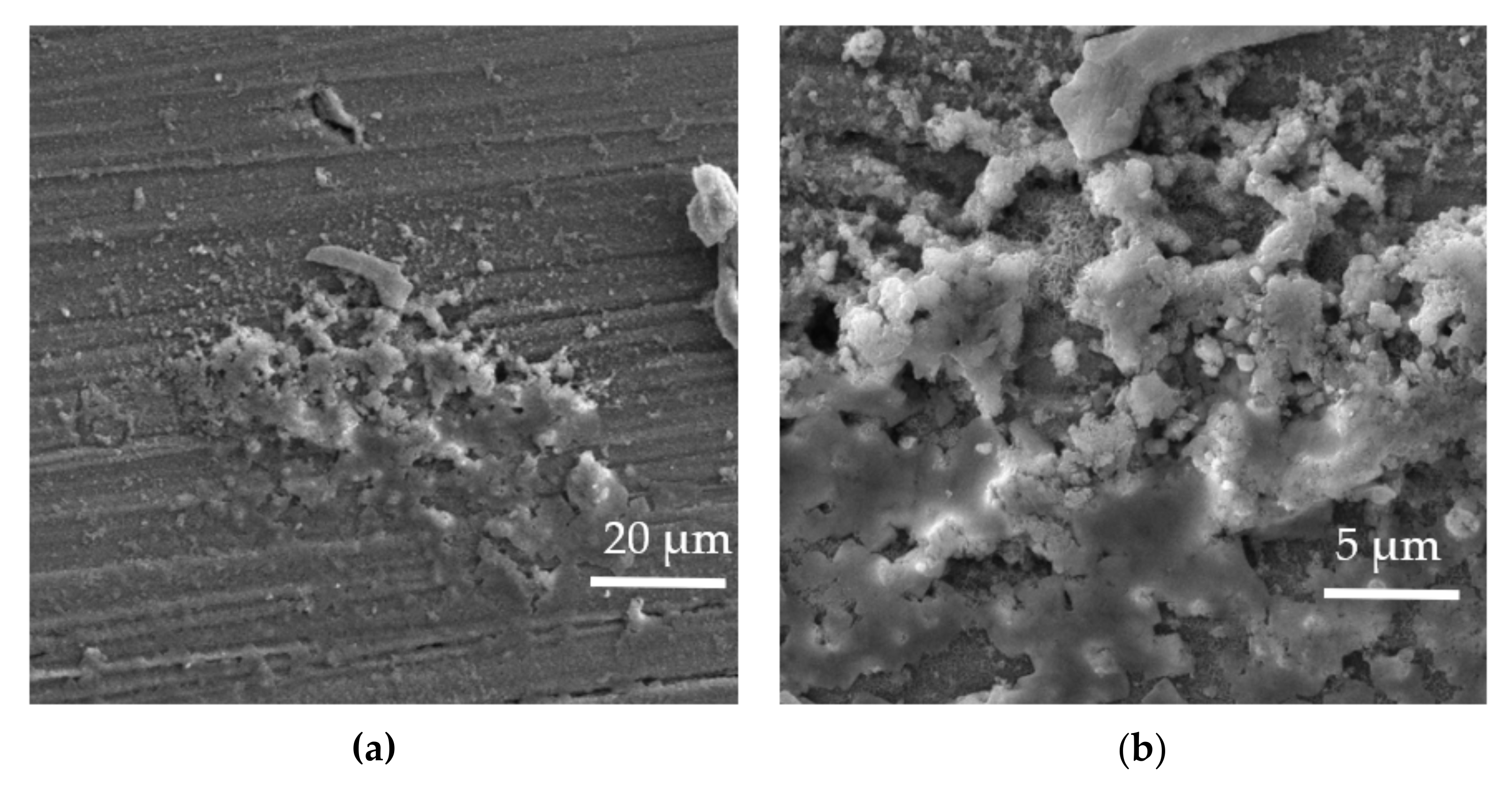
The protective ability of the as-cast surface against the corrosive medium is determined only by the formation of a soluble and porous oxide or hydroxide layer, the chemical composition of which is likely to consist of a combination of Mg(OH)2, MgO and MgCl2 [40]. When comparing between AZ91 and AZ31 magnesium alloy, the oxidic film that is naturally produced on magnesium alloy AZ91 in corrosion environments is more resistant to corrosion attack compared to the oxidic film produced on alloy AZ31. This is mainly due to the lower aluminium content in the microstructure of AZ31 and thus, lower oxide stability film with a tendency to dissolve faster than in the case of oxide produced on AZ91 [33,35,41,42]. This is confirmed when taking into account the obtained corrosion potential Ecorr from our previous work in the same solution of 0.1 M NaCl [23], where the Ecorr value reached (−1579 mV) for the as-cast surface of AZ31 magnesium alloy. Whereas in this work, Ecorr for the as-cast surface of AZ91 reached −1465 mV, which makes the difference +114 mV in favour of AZ91 in this study. It is well known that the concentration of aluminium in magnesium alloy AZ91 ranges from 35% in the β-phase to 9–6% in the α-phase, which is more than in the microstructure of AZ31 where the aluminium content in the α-phase is around 3%. From a thermodynamic point of view, magnesium and its alloys primarily produce the oxidic film MgO before Al2O3 [43]. The corrosion potential Ecorr between α- and β-phases represents different values. Arrabal et al. [44] found the difference in potentials between given phases reaches a difference of up to 160 mV. This fact can be attributed to a more positive value of Ecorr for AZ91 when compared to AZ31, from our previous study. This is also demonstrated from the microstructure, where, in Figure 3, Mg17Al12 is present in a higher content than in the microstructure of AZ31 from our previous study [45]. Merino et al. [46] pointed out that the corrosive behaviour of magnesium alloy in the electrolyte containing Cl is partially controlled by corrosion products in the form of a protective layer formed on the exposed surface, with corrosion reactions preferably located in its defective places (pores, microparticles). In the case of an as-cast surface, the intermetallic phase Mg17Al12 may be responsible for better corrosion resistance in a certain quantity and distribution, as described in the works of Song et al. [31,40]. Researchers in the work [47], performed surface potential maps and potential profiles of various intermetallic including Al–Mn type. Based on the results of the work, Al–Mn inclusions are cathodic with respect to the α-Mg matrix (410 ± 120 mV), which leads to the formation of micro-galvanic couples and therefore an enhanced corrosion rate [48]. The presence of such intermetallic in the microstructure of AZ91 is presented in Figure 3b. The value of Rp is directly related to the corrosion resistance [22,48]. As was mentioned above in the section on EIS results, the highest value of Rp was obtained after 1 h of exposure, namely 3278 Ω·cm2. This was followed by a gradual decrease which resulted in a minimum Rp value of 2507 Ω·cm2 after 12 h of exposure. Nordlien et al. [49] observed the oxidic structure and morphology of the films formed on the pure magnesium after exposure in the water for 1 h. The formed film was composed overall of a three-layer structure with an inner cellular structure layer of a thickness of 0.4–0.6 μm, followed by a middle dense layer of 20–40 nm, (MgO layer) and from the outer part platelet-like layer (Mg(OH)2 layer) [50]. However, corrosion products formed on magnesium alloys contain many defects, whereas these products are not stable in chloride solutions, and tend to lose their protective ability to withstand against a supply of Cl ions. This fact is attributed to the gradual decrease in Rp values up to 12 h of exposure, where AZ91 substrate was probably hit by a corrosive medium, which was responsible for the downtrend of the Rp evolution. Whereas, after 24 h of exposure, the Rp value increased to 2825 Ω·cm2. This is in correlation with the work of [39], where after immersion of as-cast samples in a corrosion environment representing 0.9% NaCl, a layer of corrosion products is formed on the surface, and the thickness of corrosion products increases as the exposure time increases. This means that a higher thickness of corrosion product forms a better barrier against a corrosive environment and thus, the Rp, which is where the resistance against electrons’ transfer increases. The evolution of CPE was observed in the opposite direction, as in the case of the Rp trend in this work, whereas, at the beginning of the experiment, the value of CPE reached the lowest value of 8.044 F·sn−1·10−6; after 24 h of immersion in 0.1 M NaCl, the value of CPE raised up to 9.422 F·sn−1·10−6. Similar behaviour is observed in the work [51], where the authors stated that Cdl of both magnesium alloys AZ31 and AZ91 increases during the exposure as the time increases. Since Cdl is dependent on the behaviour between the water/electrolytes uptake through the pores/defects of the surface film, an increase in Cdl with time for AZ91 and AZ31 alloy implies the deterioration of the film through the increase in porosities/defects in their oxide film [51]. Surface degradation of the as-cast surface in 0.1 M NaCl after 24 h of exposure can be seen in Figure 9a,b. SEM pictures of deteriorated as-cast surfaces clearly imply the fact that the corrosion products formed on magnesium alloys are of a nonhomogeneous nature, with many defects and irregularities that are responsible for low corrosion resistance.
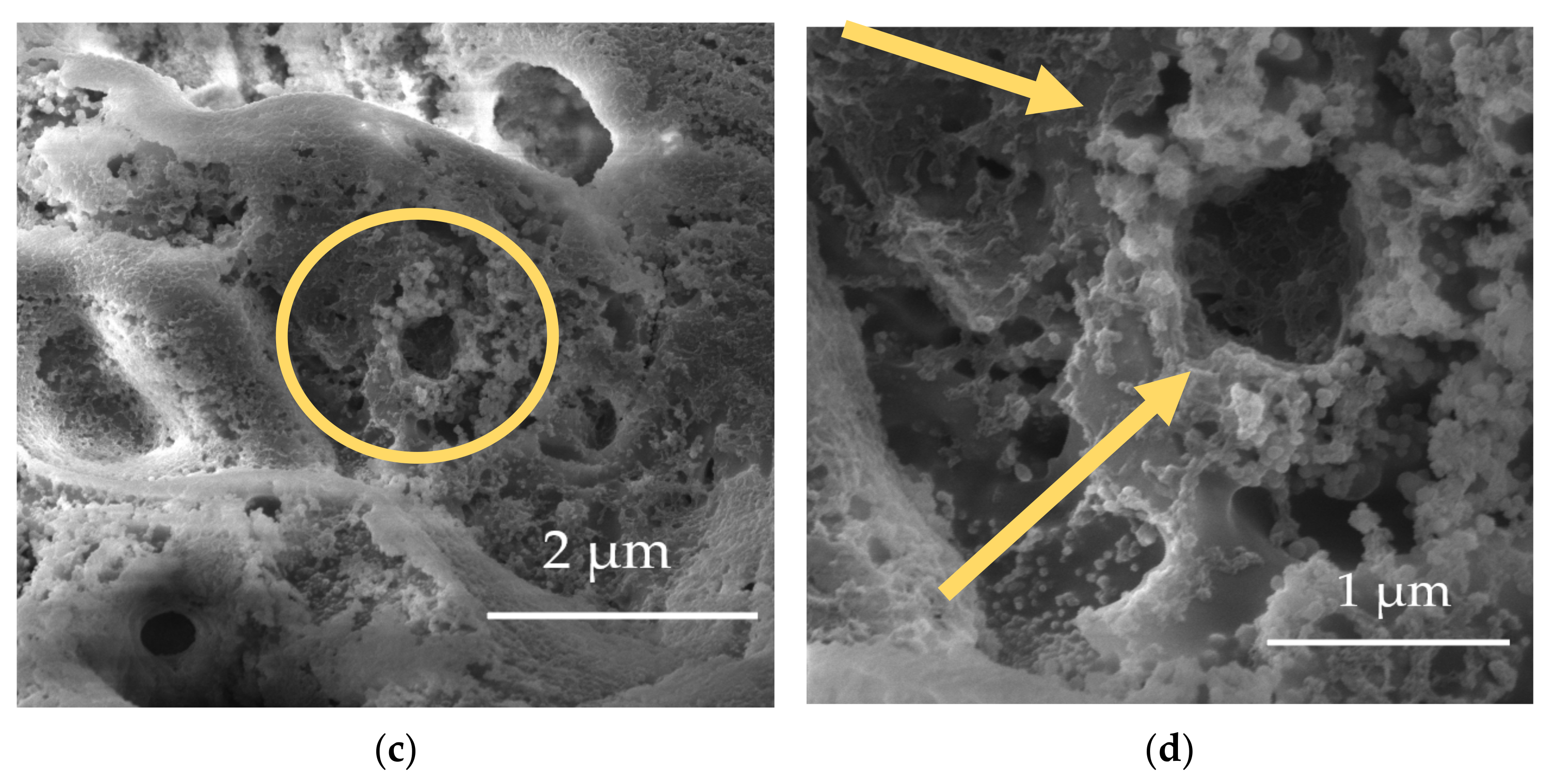
The application of plasma electrolytic oxidation on magnesium alloy AZ91 positively affects corrosion resistance in 0.1 M NaCl. Based on the results of both electrochemical methods performed to assess the corrosion resistance of PEO, the coating positively influenced the surface’s ability to withstand the supply of reactive Cl ions. Significant improvement of corrosion properties by creating PEO coating on magnesium alloy AZ91 also confirms other works [52,53,54,55]. The presence of intermetallic compounds, including the compound (Mg17Al12) in the α-phase in the microstructure of AZ91 magnesium alloy, has a significant influence during the evolution of the PEO process itself, and consequently on the chemical composition and the resulting corrosion resistance of the formed oxidic coating [55,56,57]. Aluminium may appear in the PEO coating in the form of different chemical compounds, including MgAl2O4 or Al2O3 [37]. After 1 h of exposure, the as-cast surface reached 3278 Ω·cm2 while the PEO coated surface was characterised by the value of 429,970 Ω·cm2, which is more than 130 times in favour of a PEO coated surface. After 4 h of exposure, the value of Rp for the PEO coating decreased by almost 40% to the value of 262,285 Ω·cm2. This decrease was probably caused when the electrolyte penetrated through the pores present in the PEO coating and hit the alloy. This was also stated in the work [55], that corrosive medium can penetrate through pores and cracks in the PEO coating and subsequently reach the substrate, leading to a local corrosion attack. During the subsequent interval from 12 h up to 24 h of exposure, the evolution of Rp was accompanied by the increase in the Rp value to 207,715 Ω·cm2 after 24 h, from its lowest value of 191,805 Ω·cm2 obtained after 12 h of exposure in 0.1 M NaCl. This may be caused because of the formation of corrosion product which partially filled the pores and created a barrier against aggressive Cl in the coating. The formation of oxidation products could slow down the ionic dissolution rate of immersed metal, which is responsible for an increase in Rp during the interval between 3~24 h of exposure in the work [50,57]. When comparing with the Rp values of the PEO coating prepared in the identical phosphate electrolyte in the work [34], the differences in Rp values obtained in 0.1 M NaCl after 24 h in this work were higher by one order of magnitude, as in the mentioned work. Differences in the Rp value might be caused by the usage of DC current mode without a pulsed regime in this work, whereas in the previous study, the DC pulsed regime with a pulse ratio of ton:toff = 2 ms:20 ms was used. Due to the fact that corrosion products are non-uniform and soluble in aggressive environments containing Cl ions, the barrier effect is not temporary [50]. Moreover, the accumulation of corrosion products will increase the stress on the barrier coating. A volume expansion of the barrier coating may be presumed due to the transformation of unstable compound MgO into Mg (OH)2 [40]. Therefore, micro-cracks and degradation inside the barrier coating may be indicated, which will enhance the migration rate of the aggressive medium through the degraded PEO coating and thus, localised corrosion may occur after a longer exposure time [56,57]. Degradation of PEO coating in 0.1 M NaCl after 24 h of exposure is shown in the SEM pictures shown in Figure 10a–d. Light orange arrows and circles show the localised degradation areas where the dissolution of the coating took place during exposure, and therefore the protective ability of the coating was weakened, which was reflected by the lower corrosion resistance values after 24 h compared to the initial period of EIS measurements. On the other hand, a light blue coloured circle with an arrow shows the area in which corrosion did not cause visible changes in the top surface of the PEO coating. The authors of the following studies [34,57] stated that the coatings produced from silicate electrolytes are more uniform and denser compared with the coatings obtained from phosphate electrolytes. Correspondingly, this fact is obvious in Figure 3a, where the huge pores, together with other defects, are visible. However, when comparing the results from EIS measurements, namely the value of the main characteristic Rp from the work [34], the values for PEO coating prepared in silicate electrolyte are lower almost by 50% compared to the value obtained in this work. This, in fact, may be attributed to the DC regime variations between these studies.
The Rp value of 29,297 Ω·cm2 on PEO coated AZ31 magnesium alloy from our previous work [22] represented only 14% of the Rp value obtained in this work after 24 h of exposure to 0.1 M NaCl. When comparing Rp between as-cast and PEO coating in this work, the increase in Rp value after 24 h was more than 73 times in favour of the PEO coating. Whereas, during the whole exposure, the Rp values for PEO coating were higher by 2 orders in magnitude than those for the as-cast surface. A recent experimental study by Kerner and Pajkossy [55] showed that the capacitance dispersion on solid electrodes was due to surface disorder (i.e., heterogeneities on the atomic scale) and due to the roughness (i.e., geometric irregularities much larger than those on the atomic scale). A gradual rise of double-layer capacitance (Cdl) of the coating was observed with the passage of immersion time in the work [58,59,60]. In the literature, it is well documented that during the initial stage of immersion, the Cdl remains unaffected by the cracks and defects in the coating. However, after a longer immersion time, the Cdl increases because of the uptake of electrolytes through the abovementioned pores and defects in the coating [57].
This is in correlation with the evolution of CPE in this work, where the opposite trend in the evolution of CPE against the line of Rp was observed, and this fact was attributed to the growth of surface disorder. This may be caused mainly by the formation of corrosion products, which leads to the non-uniform distribution of current. Degradation of both as-cast and PEO surfaces in 0.1 M NaCl was accompanied by a decrease in Rp during 24 h of exposure. The constant phase element (CPE) behaves like a Warburg element if n = 0.5, however, if the value of n = 1, the CPE represents the capacitor. The CPE value depends on several parameters, such as surface roughness and different thicknesses or coating compositions, on which the speed of ongoing processes on the electrode surface also depends [56,57].
Photo documentation in Figure 4a–c showed that defects are present in PEO coating with a different nature and intensity. The corrosive medium can penetrate through pores and cracks in the PEO coating and subsequently reach the substrate (AZ91), leading to local corrosion during longer exposures [56]. For example, in the following works [33,35], it has been demonstrated that, among other factors, the presence of the β-phase (Mg17Al12) leads to nonhomogeneous growth of the PEO coating. Khaselev et al. [53] found that the primary production of the PEO coating is formed at the α- and then at the β-phase. Further work by the authors Gunduz et al. [54] and Khaselev et al. [52] state that aluminium and zinc in the microstructure of magnesium alloys of the Mg-Al, Mg-Zn system affect the thickness and morphology of the prepared PEO coating. This is achieved by reducing its thickness and leading to a rougher structure with a higher content of more intense discharges, which are responsible for pores across the PEO coating [53,60]. Coating defects (pores and cracks) are fatal due to the fact that they negatively affect the barrier effect of PEO coating on magnesium alloy [1,60]. The surface morphology of the oxide coating on magnesium alloys AZ31 and AZ91 differs substantially. The formed coating on magnesium alloy AZ91 is more uneven than in the case of alloy AZ31 with a lower aluminium content, and thus a lower content of β-phase, whose effect on the formation of the PEO coating is given above [42]. The presence of micro defects in the PEO coating, together with their size and quantity, determines the compactness and integrity of the oxide coating formed, which is also directly related to corrosion resistance [7,37]. All inequalities and non-homogeneities of the coating cause an increase in roughness, while at the same time, the electrochemically active area increases [35,36,60,61], which in turn leads to more intense infestation and degradation of the PEO surface in corrosion environments.
Based on the results from the PDP authors in the following study [35], the value of corrosion current density on AZ91 is lower than on AZ31, both in the as-cast state and after the preparation of PEO coating. The value of the icorr is very important, given that its value is directly related to the value of the corrosion rate (rcorr) [39,61]. Results from PDP in this work revealed that the value of Ecorr for PEO coating shifted towards more negative values by a difference of 160 mV, whereas thermodynamic nobility/stability of the surface is expressed precisely by this characteristic [10]. The more positive its value is, the more noble/stable the surface from a thermodynamic point of view is. This means that PEO coating has a negative effect on the thermodynamic nobility of the surface, as its value is more negative than that of the as-cast surface. However, the resulting corrosion rate rcorr is significantly affected by the abovementioned icorr value. The more electro-negative Ecorr value for PEO coating, by the above difference, will be advantageous in the case of coating damage, as there will be a thermodynamic tendency to protect bulk material and thus heal it with corrosion products [23]. The defection of PEO coatings formed on magnesium alloys limits the wider use of these materials and can negatively affect the long-term corrosion resistance. In certain specific applications, porosity can be beneficial, in particular, for biomedical use as a material for biodegradable implants [61]. In this case, however, it is only a fraction of the use, when the porousness and defectivity of the created PEO coatings on magnesium alloys are beneficial. Therefore, enlarging the database of specific process parameters for the PEO process may grant inspiration for other studies.

5. Conclusions

On the basis of the measurements and analyses carried out, the following conclusions are drawn:
  • The oxidic coating prepared by plasma electrolytic oxidation on magnesium alloy AZ91 represents a typical porous structure with variable pore and micro-crack size.
  • In terms of increasing corrosion resistance, the prepared PEO coating increased the polarisation resistance value Rp after 24 h of exposure in 0.1 M NaCl more than 73 times to 207,515 Ω·cm2, while the as-cast surface reached only 2825 Ω·cm2.
  • When comparing the Rp values from the EIS measurements from our previous work [22], the obtained value of Rp 29,297 Ω·cm2 from our previous work on PEO coated AZ31 magnesium alloy represented only 14% of the Rp value obtained on PEO coated AZ91 in this work after 24 h of exposure in 0.1 M NaCl.
  • A significant increase in corrosion resistance was also demonstrated by results obtained from potentiodynamic polarisation in 0.1 M NaCl as follows: The corrosion current density of icorr for the PEO coating decreased by more than 27 times to 0.14 μA·cm−2, compared to the as-cast surface (3.86 μA·cm−2).
  • From a thermodynamic point of view, the corrosion potential Ecorr shifted towards a more negative value (−1625 mV) for the PEO surface compared to the Ecorr value at the level (−1465 mV) measured for the as-cast surface.
  • However, when comparing the results of Ecorr values between as-cast surfaces of AZ31 from our previous work [23] and AZ91 from this study, the AZ91 magnesium alloy in this work was characterised by a shift of Ecorr towards more positive values by the difference of +114 mV.

Author Contributions

Outline of performed experiments, writing and supervision, M.Š. Conceptualization, D.K., V.K. and Z.F. measurements and data analysis. J.P. and M.G. SEM images, data analysis and processing of results. B.H. conceptualization and funding acquisition. All authors have read and agreed to the published version of the manuscript.

Funding

The research was financially supported by the Science Grant Agency of the Slovak Republic through project No. 15901, and also thanks to support under the operational programme Integrated Infrastructure 2014–2020 for the project: Innovative solutions of fuel, energy and safety components of transport vehicles, with ITMS project code 313011V334, co-financed by the European Regional Development Fund. This paper was also supported under the project of Operational Programme Integrated Infrastructure: Independent research and development of technological kits based on wearable electronics products, as tools for raising hygienic standards in a society exposed to the virus causing the COVID-19 disease, ITMS2014+ code 313011ASK8. The project is co-funded by the European Regional Development Fund. The authors also thank the Scientific Grant Agency of the Ministry of Education, Science, Research and Sport of the Slovak Repblic and the Slovak Academy of Sciences for their support through projects VEGA no. 1/0117/21 and 1/0153/21.

Institutional Review Board Statement

Not applicable.

Informed Consent Statement

Not applicable.

Data Availability Statement

Not applicable.

Conflicts of Interest

The authors declare no conflict of interest.

References

  1. Esmaily, M.; Shahabi-Navid, M.; Svensson, J.E.; Halvarsson, M.; Nyborg, L.; Cao, Y.; Johansson, L.G. Influence of Temperature on the Atmospheric Corrosion of the Mg-Al Alloy AM50. Corros. Sci. 2015, 90, 420–433. [Google Scholar] [CrossRef] [Green Version]
  2. Barati Darband, G.; Aliofkhazraei, M.; Hamghalam, P.; Valizade, N. Plasma Electrolytic Oxidation of Magnesium and Its Alloys: Mechanism, Properties and Applications. J. Magnes. Alloy. 2017, 5, 74–132. [Google Scholar] [CrossRef]
  3. Monteiro, W.A.; Buso, S.J.; Silva, L.V. Application of Magnesium Alloys in Transport. In New Features on Magnesium Alloys; InTech: London, UK, 2012. [Google Scholar]
  4. Westengen, H.; Aune, T.K. 5 Magnesium Casting Alloys 5.1 Casting Alloys; Springer: Berlin/Heidelberg, Germany, 2006. [Google Scholar]
  5. Mondet, M.; Barraud, E.; Lemonnier, S.; Guyon, J.; Allain, N.; Grosdidier, T. Microstructure and Mechanical Properties of AZ91 Magnesium Alloy Developed by Spark Plasma Sintering. Acta Mater. 2016, 119, 55–67. [Google Scholar] [CrossRef]
  6. Hadzima, B.; Liptáková, T. Základy Elektrochemickej Korózie Kovov; EDIS-Žilinská Univerzita: Žilina, Slovak, 2008. [Google Scholar]
  7. Clyne, T.W.; Troughton, S.C. A Review of Recent Work on Discharge Characteristics during Plasma Electrolytic Oxidation of Various Metals. Int. Mater. Rev. 2019, 64, 127–162. [Google Scholar] [CrossRef] [Green Version]
  8. Zeng, R.-C.; Zhang, J.; Huang, W.-J.; Dietzel, W.; Kainer, K.U.; Blawert, C.; Wei, K. Science Review of Studies on Corrosion of Magnesium Alloys. Trans. Nonferrous Met. Soc. China 2006, 16, s763–s771. [Google Scholar] [CrossRef]
  9. Amirudin, A.; Thierry, D. Progress in Organic Coatings Application of Electrochemical Impedance Spectroscopy to Study the Degradation of Polymer-Coated Metals. Prog. Org. Coat. 1995, 26, 1–28. [Google Scholar] [CrossRef]
  10. Bagherifard, S.; Hickey, D.J.; Fintová, S.; Pastorek, F.; Fernandez-Pariente, I.; Bandini, M.; Webster, T.J.; Guagliano, M. Effects of Nanofeatures Induced by Severe Shot Peening (SSP) on Mechanical, Corrosion and Cytocompatibility Properties of Magnesium Alloy AZ31. Acta Biomater. 2018, 66, 93–108. [Google Scholar] [CrossRef] [Green Version]
  11. Czerwinski, F. Controlling the Ignition and Flammability of Magnesium for Aerospace Applications. Corros. Sci. 2014, 86, 1–16. [Google Scholar] [CrossRef]
  12. Wang, B.J.; Xu, D.K.; Cai, X.; Qiao, Y.X.; Sheng, L.Y. Effect of Rolling Ratios on the Microstructural Evolution and Corrosion Performance of an As-Rolled Mg-8 wt.% Li Alloy. J. Magnes. Alloy. 2021, 9, 560–568. [Google Scholar] [CrossRef]
  13. Hussein, R.O.; Nie, X.; Northwood, D.O. Plasma Electrolytic Oxidation Coatings on Mg-Alloys for Improved Wear and Corrosion Resistance. Corros. Mater. Perform. Cathodic Prot. 2017, 99, 133–147. [Google Scholar]
  14. Chen, Y.; Lu, X.; Lamaka, S.V.; Ju, P.; Blawert, C.; Zhang, T.; Wang, F.; Zheludkevich, M.L. Active Protection of Mg Alloy by Composite PEO Coating Loaded with Corrosion Inhibitors. Appl. Surf. Sci. 2020, 504, 144462. [Google Scholar] [CrossRef]
  15. Zhu, L.; Qiu, J.; Chen, J.; Zhang, W.; Chen, Z.; Zhang, T.; Wang, F. Microstructure and Corrosion Resistance of the PEO Coating on Extruded Al6Cu Alloy. Surf. Coat. Technol. 2019, 369, 116–126. [Google Scholar] [CrossRef]
  16. Feliu, S. Electrochemical Impedance Spectroscopy for the Measurement of the Corrosion Rate of Magnesium Alloys: Brief Review and Challenges. Metals 2020, 10, 775. [Google Scholar] [CrossRef]
  17. Esmaily, M.; Svensson, J.E.; Fajardo, S.; Birbilis, N.; Frankel, G.S.; Virtanen, S.; Arrabal, R.; Thomas, S.; Johansson, L.G. Fundamentals and Advances in Magnesium Alloy Corrosion. Prog. Mater. Sci. 2017, 89, 92–193. [Google Scholar] [CrossRef]
  18. Blawert, C.; Dietzel, W.; Ghali, E.; Song, G. Anodizing Treatments for Magnesium Alloys and Their Effect on Corrosion Resistance in Various Environments. Adv. Eng. Mater. 2006, 8, 511–533. [Google Scholar] [CrossRef]
  19. Curran, J.A.; Clyne, T.W. The Thermal Conductivity of Plasma Electrolytic Oxide Coatings on Aluminium and Magnesium. Surf. Coat. Technol. 2005, 199, 177–183. [Google Scholar] [CrossRef]
  20. Zhao, H.; Zhao, C.; Yang, Y.; Wang, Y.; Sheng, L.; Li, Y.; Huo, M.; Zhang, K.; Xing, L.; Zhang, G. Study on the Microstructure and Mechanical Properties of a Ti/Mg Alloy Clad Plate Produced by Explosive Welding. Metals 2022, 12, 399. [Google Scholar] [CrossRef]
  21. Zhang, P.; Nie, X.; Hu, H. Wear and Galvanic Corrosion Protection of Mg Alloy via Plasma Electrolytic Oxidation Process for Mg Engine Application. SAE Tech. Pap. 2009, 1, 0790. [Google Scholar]
  22. Hadzima, B.; Kajánek, D.; Jambor, M.; Drábiková, J.; Březina, M.; Buhagiar, J.; Pastorková, J.; Jacková, M. Peo of Az31 Mg Alloy: Effect of Electrolyte Phosphate Content and Current Density. Metals 2020, 10, 1521. [Google Scholar] [CrossRef]
  23. Kajánek, D.; Hadzima, B.; Tkacz, J.; Pastorková, J.; Jacková, M.; Wasserbauer, J. Corrosion Resistance of AZ31 Magnesium Alloy Treated by Plasma Electrolytic Oxidation. Koroze A Ochr. Mater. 2019, 63, 65–71. [Google Scholar] [CrossRef] [Green Version]
  24. Pastorek, F.; Štrbák, M.; Kajánek, D.; Jacková, M.; Pastorková, J.; Florková, Z. Corrosion Behaviour of Preserved Peo Coating on Az31 Magnesium Alloy. Commun. Sci. Lett. Univ. Zilina 2021, 23, B76–B88. [Google Scholar] [CrossRef]
  25. Yang, C.; Cai, H.; Cui, S.; Huang, J.; Zhu, J.; Wu, Z.; Ma, Z.; Fu, R.K.Y.; Sheng, L.; Tian, X.; et al. A Zinc-Doped Coating Prepared on the Magnesium Alloy by Plasma Electrolytic Oxidation for Corrosion Protection. Surf. Coat. Technol. 2022, 433, 128148. [Google Scholar] [CrossRef]
  26. Kang, L.; Shi, L.; Zeng, Q.; Liao, B.; Wang, B.; Guo, X. Melamine Resin-Coated Lignocellulose Fibers with Robust Superhydrophobicity for Highly Effective Oil/Water Separation. Sep. Purif. Technol. 2021, 279, 119793. [Google Scholar] [CrossRef]
  27. Guo, Y.; Rogov, A.; Hird, A.; Mingo, B.; Matthews, A.; Yerokhin, A. Plasma Electrolytic Oxidation of Magnesium by Sawtooth Pulse Current. Surf. Coat. Technol. 2022, 429, 127938. [Google Scholar] [CrossRef]
  28. Lein, J.E.; Kr Aune, T.; Ni sancioglu, K. The Role of Mg17AI12 Phase in the Corrosion of Mg AIIoy AZ91. Corrosion 1989, 45, 741–748. [Google Scholar]
  29. Zeng, G.; Xian, J.W.; Gourlay, C.M. Nucleation and Growth Crystallography of Al8Mn5 on B2-Al(Mn,Fe) in AZ91 Magnesium Alloys. Acta Mater. 2018, 153, 364–376. [Google Scholar] [CrossRef] [Green Version]
  30. Lun Sin, S.; Dubé, D.; Tremblay, R. An Investigation on Microstructural and Mechanical Properties of Solid Mould Investment Casting of AZ91D Magnesium Alloy. Mater. Charact. 2008, 59, 178–187. [Google Scholar] [CrossRef]
  31. Song, G.L.; Atrens, A. Corrosion Mechanisms of Magnesium Alloys. Adv. Eng. Mater. 1999, 1, 11–33. [Google Scholar] [CrossRef]
  32. Kiełbus, A.; Moskal, G. The Influence of Mg17Al12 Phase Volume Fraction on the Corrosion Behaviour of AZ91 Magnesium Alloy. Int. J. Microstruct. Mater. Prop. 2009, 4, 196–206. [Google Scholar]
  33. Martin, J.; Nominé, A.V.; Stef, J.; Nominé, A.; Zou, J.X.; Henrion, G.; Grosdidier, T. The Influence of Metallurgical State of Substrate on the Efficiency of Plasma Electrolytic Oxidation (PEO) Process on Magnesium Alloy. Mater. Des. 2019, 178, 107859. [Google Scholar] [CrossRef]
  34. Liang, J.; Srinivasan, P.B.; Blawert, C.; Störmer, M.; Dietzel, W. Electrochemical Corrosion Behaviour of Plasma Electrolytic Oxidation Coatings on AM50 Magnesium Alloy Formed in Silicate and Phosphate Based Electrolytes. Electrochim. Acta 2009, 54, 3842–3850. [Google Scholar] [CrossRef]
  35. Rakoch, A.G.; Monakhova, E.P.; Khabibullina, Z.V.; Serdechnova, M.; Blawert, C.; Zheludkevich, M.L.; Gladkova, A.A. Plasma Electrolytic Oxidation of AZ31 and AZ91 Magnesium Alloys: Comparison of Coatings Formation Mechanism. J. Magnes. Alloy. 2020, 8, 587–600. [Google Scholar] [CrossRef]
  36. Vladimirov, B.V.; Krit, B.L.; Lyudin, V.B.; Morozova, N.V.; Rossiiskaya, A.D.; Suminov, I.V.; Epel’feld, A.V. Microarc Oxidation of Magnesium Alloys: A Review. Surf. Eng. Appl. Electrochem. 2014, 50, 195–232. [Google Scholar] [CrossRef]
  37. Kaseem, M.; Fatimah, S.; Nashrah, N.; Ko, Y.G. Recent Progress in Surface Modification of Metals Coated by Plasma Electrolytic Oxidation: Principle, Structure, and Performance. Prog. Mater. Sci. 2021, 117, 100735. [Google Scholar] [CrossRef]
  38. Laleh, M.; Rouhaghdam, A.S.; Shahrabi, T.; Shanghi, A. Effect of Alumina Sol Addition to Micro-Arc Oxidation Electrolyte on the Properties of MAO Coatings Formed on Magnesium Alloy AZ91D. J. Alloys Compd. 2010, 496, 548–552. [Google Scholar] [CrossRef]
  39. Hadzima, B.; Mhaede, M.; Pastorek, F. Electrochemical Characteristics of Calcium-Phosphatized AZ31 Magnesium Alloy in 0.9 % NaCl Solution. J. Mater. Sci. Mater. Med. 2014, 25, 1227–1237. [Google Scholar] [CrossRef]
  40. Atrens, A.; Song, G.L.; Cao, F.; Shi, Z.; Bowen, P.K. Advances in Mg Corrosion and Research Suggestions. J. Magnes. Alloy. 2013, 1, 177–200. [Google Scholar] [CrossRef] [Green Version]
  41. Song, G.; Atrens, A. Recent insights into the mechanism of magnesium corrosion and research suggestions. Adv. Eng. Mater. 2007, 9, 177–183. [Google Scholar] [CrossRef]
  42. Kiełbus, A.; Jarosz, R.; Gryc, A. Effect of Modification on Microstructure and Properties of AZ91 Magnesium Alloy. Crystals 2020, 10, 536. [Google Scholar] [CrossRef]
  43. Zhang, R.F.; Zhang, S.F. Formation of Micro-Arc Oxidation Coatings on AZ91HP Magnesium Alloys. Corros. Sci. 2009, 51, 2820–2825. [Google Scholar] [CrossRef]
  44. Arrabal, R.; Matykina, E.; Viejo, F.; Skeldon, P.; Thompson, G.E. Corrosion Resistance of WE43 and AZ91D Magnesium Alloys with Phosphate PEO Coatings. Corros. Sci. 2008, 50, 1744–1752. [Google Scholar] [CrossRef]
  45. Kajánek, D.; Hadzima, B.; Buhagiar, J.; Wasserbauer, J.; Jacková, M. Corrosion Degradation of AZ31 Magnesium Alloy Coated by Plasma Electrolytic Oxidation. Transp. Res. Procedia 2019, 40, 51–58. [Google Scholar] [CrossRef]
  46. Merino, M.C.; Pardo, A.; Arrabal, R.; Merino, S.; Casajús, P.; Mohedano, M. Influence of Chloride Ion Concentration and Temperature on the Corrosion of Mg-Al Alloys in Salt Fog. Corros. Sci. 2010, 52, 1696–1704. [Google Scholar] [CrossRef]
  47. Arrabal, R.; Mingo, B.; Pardo, A.; Matykina, E.; Mohedano, M.; Merino, M.C.; Rivas, A.; Maroto, A. Role of Alloyed Nd in the Microstructure and Atmospheric Corrosion of As-Cast Magnesium Alloy AZ91. Corros. Sci. 2015, 97, 38–48. [Google Scholar] [CrossRef]
  48. Attarzadeh, N.; Kazemi, A.; Molaei, M.; Fattah-alhosseini, A. Multipurpose Surface Modification of PEO Coatings Using Tricalcium Phosphate Addition to Improve the Bedding for Apatite Compounds. J. Alloys Compd. 2021, 877, 160275. [Google Scholar] [CrossRef]
  49. Nordlien, J.H.; One, S.; Masuko, N.; Nianciow, K. Morphology and Structure of Oxide Films Formed on Magnesium by Exposure to Air and Water. J. Electrochem. Soc. 1995, 142, 1330. [Google Scholar] [CrossRef]
  50. Singh, I.B.; Singh, M.; Das, S. A Comparative Corrosion Behavior of Mg, AZ31 and AZ91 Alloys in 3.5% NaCl Solution. J. Magnes. Alloy. 2015, 3, 142–148. [Google Scholar] [CrossRef] [Green Version]
  51. Liu, C.; Liang, J.; Zhou, J.; Li, Q.; Peng, Z.; Wang, L. Characterization and Corrosion Behavior of Plasma Electrolytic Oxidation Coated AZ91-T6 Magnesium Alloy. Surf. Coat. Technol. 2016, 304, 179–187. [Google Scholar] [CrossRef]
  52. Khaselev, O.; Weiss, D.; Yahalom, J. Structure and Composition of Anodic® lms Formed on Binary Mg±Al Alloys in KOH±aluminate Solutions under Continuous Sparking. Corros. Sci. 2001, 43, 1295–1307. [Google Scholar] [CrossRef]
  53. Majumdar, J.D.; Bhattacharyya, U.; Biswas, A.; Manna, I. Studies on Thermal Oxidation of Mg-Alloy (AZ91) for Improving Corrosion and Wear Resistance. Surf. Coat. Technol. 2008, 202, 3638–3642. [Google Scholar] [CrossRef]
  54. Gunduz, K.O.; Oter, Z.C.; Tarakci, M.; Gencer, Y. Plasma Electrolytic Oxidation of Binary Mg-Al and Mg-Zn Alloys. Surf. Coat. Technol. 2017, 323, 72–81. [Google Scholar] [CrossRef]
  55. Kerner, Z.; Pajkossy, T. Impedance of Rough Capacitive Electrodes: The Role of Surface Disorder. J. Electroanal. Chem. 1998, 448, 139–142. [Google Scholar] [CrossRef]
  56. Liang, J.; Srinivasan, P.B.; Blawert, C.; Dietzel, W. Influence of Chloride Ion Concentration on the Electrochemical Corrosion Behaviour of Plasma Electrolytic Oxidation Coated AM50 Magnesium Alloy. Electrochim. Acta 2010, 55, 6802–6811. [Google Scholar] [CrossRef] [Green Version]
  57. Ruhi, G.; Modi, O.P.; Singh, I.B. Corrosion Behaviour of Nano Structured Sol-Gel Alumina Coated 9Cr-1Mo Ferritic Steel in Chloride Bearing Environments. Surf. Coat. Technol. 2009, 204, 359–365. [Google Scholar] [CrossRef]
  58. Hussein, R.O.; Nie, X.; Northwood, D.O. An Investigation of Ceramic Coating Growth Mechanisms in Plasma Electrolytic Oxidation (PEO) Processing. Electrochim. Acta 2013, 112, 111–119. [Google Scholar] [CrossRef]
  59. Olivier, M.-G.; Poelman, M. Use of Electrochemical Impedance Spectroscopy (EIS) for the Evaluation of Electrocoatings Performances; Books on Demand: Norderstedt, Germany, 2012. [Google Scholar]
  60. Rahman, S.U.; Atta Ogwu, A. Corrosion and Mott-Schottky Probe of Chromium Nitride Coatings Exposed to Saline Solution for Engineering and Biomedical Applications. In Advances in Medical and Surgical Engineering; Elsevier: Amsterdam, The Netherlands, 2020; pp. 239–265. [Google Scholar]
  61. M.Rúa, J.; Zuleta, A.A.; Ramírez, J.; Fernández-Morales, P. Micro-Arc Oxidation Coating on Porous Magnesium Foam and Its Potential Biomedical Applications. Surf. Coat. Technol. 2019, 360, 213–221. [Google Scholar] [CrossRef]
Figure 1. Equipment set-up for PEO process.
Coatings 12 00566 g001
Figure 2. Equivalent circuits for Nyquist plots analysis: (a) simple EEC, (b) complex EEC.
Coatings 12 00566 g002
Figure 3. Microstructure and chemical composition of AZ91, Nital 2% (a) α-phase together with intermetallic phases, (b) EDX analysis of the microstructure chemical composition of various intermetallics.
Coatings 12 00566 g003
Figure 4. SEM images of PEO coating (a) cross-section of interfaces with microstructural defects, (b) substrate/coating interface together with principal corrosion product formation, (c) EDX analysis of PEO coating.
Coatings 12 00566 g004aCoatings 12 00566 g004b
Figure 5. SEM images of PEO coating surface morphology, (a) SEM magnification 5000×, (b) SEM magnification 10,000×.
Coatings 12 00566 g005
Figure 6. Electrochemical impedance behaviour of the as-cast AZ91 after different exposure times in 0.1 M NaCl solution, (a) Nyquist plots, (b) Bode plots.
Coatings 12 00566 g006
Figure 7. Electrochemical impedance behaviour of the PEO coated AZ91 after different exposure times in 0.1 M NaCl solution, (a) Nyquist plots, (b) Bode plots.
Coatings 12 00566 g007
Figure 8. Potentiodynamic polarisation curves for as-cast and PEO surfaces in 0.1 M NaCl.
Coatings 12 00566 g008
Figure 9. SEM images of PEO coating degradation in 0.1 M NaCl after 24 h of exposure, (a) image of formed corrosion product, (b) detailed image of corrosion product defective structure.
Coatings 12 00566 g009
Figure 10. (ad) SEM images of PEO coating degradation in 0.1 M NaCl after 24 h of exposure with different magnifications, (ad) different magnifications of the degraded PEO coating.
Coatings 12 00566 g010aCoatings 12 00566 g010b
Table 1. Chemical composition of magnesium alloy AZ91.
ElementAlZnMnSiCaFeMg
wt.%8.770.680.2180.1680.0010.00590.20
Table 2. Average thickness of PEO coating and roughness parameters of as-cast and PEO surface.
SurfaceCoating Thickness (μm)Roughness (μm)
PEO16 ± 21.27 ± 0.64.92 ± 1.8−0.63 ± 0.4
As-cast 0.165 ± 0.11.176 ± 0.1−1.018 ± 0.1
Table 3. Electrochemical characteristics of as-cast AZ91 in 0.1 M NaCl.
TimeRs
(Ω·cm2)
Rp1
(Ω·cm2)
Rp
(Ω·cm2)
CPE1
(F·sn−1·10−6)
n1
1 h100318032808.050.9
2 h100271027108.100.9
4 h95224022408.650.9
12 h95241024108.950.89
24 h95273027309.500.89
Table 4. Electrochemical characteristics of PEO coated surface in 0.1 M NaCl.
TimeRs
(Ω·cm2)
Rp1
(Ω·cm2)
Rp2
(Ω·cm2)
Rp
(Ω·cm2)
CPE1
(F·sn−1·10−6)
CPE2
(F·sn−1·10−6)
n1n2
1 h9526,130403,840429,9700.803.900.70.7
2 h9018,250330,450348,7000.686.600.70.6
4 h904435257,850262,2850.875.700.60.9
12 h1001855189,950191,8050.685.700.90.8
24 h952170205,345207,5158.054.300.80.6
Table 5. Electrochemical characteristics contained from Nyquist diagrams after 1 h of exposure in 0.1 M NaCl electrolyte.
SurfaceEcorr
(mV)
Epitt
(mV)
icorr
(µA·cm−2)
βa
(mV/dec.)
βc
(mV/dec.)
rcorr
(mm·year−1·10−3)
As-cast−1465−14103.867015087.5
PEO−1625−14450.142401653.25
Publisher’s Note: MDPI stays neutral with regard to jurisdictional claims in published maps and institutional affiliations.