Article

Optimization of AZ31B Magnesium Alloy Anodizing Process in NaOH-Na2SiO3-Na2B4O7 Environmental-Friendly Electrolyte

College of Biological, Chemical Science and Engineering, Jiaxing University, Jiaxing 314001, China
*
Authors to whom correspondence should be addressed.
Coatings 2022, 12(5), 578; https://doi.org/10.3390/coatings12050578
Submission received: 28 March 2022 / Revised: 20 April 2022 / Accepted: 21 April 2022 / Published: 24 April 2022
(This article belongs to the Special Issue Surface Plasma Treatments)

Abstract

:
The optimization of NaOH-Na2SiO3-Na2B4O7 electrolyte for the plasma electrolytic oxidation of AZ31B magnesium alloy was investigated through orthogonal tests. The properties of the anodized films were evaluated by film thickness, roughness measurements, salt spray tests, scanning electron microscopy (SEM), X-ray diffraction (XRD) and potentiodynamic polarization tests, respectively. The orthogonal tests revealed that the optimal formulation of the electrolyte comprised NaOH 45 g/L, Na2SiO3 50 g/L, and Na2B4O7 90 g/L. NaOH exhibited the most significant effect on film thickness, while Na2SiO3 had the greatest effect on corrosion resistance. Moreover, the optimal electrical parameters were also obtained with the values of current density 1 A /dm2, oxidation time 15 min, pulse frequency 200 Hz and duty cycle of 10%. The surface morphology of the anodized coating formed under optimal conditions was uniform and compact. Furthermore, the phase compositions of all samples were mainly composed of MgO and Mg2SiO4. The corrosion potential, corrosion current density and polarization resistance of the prepared coating by plasma electrolytic oxidation improved remarkably compared with that of the substrate.

1. Introduction

Magnesium alloy has the advantages of being lightweight, strong, good shock absorption, electromagnetic shielding and strong radiation resistance, etc., [1,2]. This alloy is known as “green engineering material in the 21st century” owing to its various applications such as in the automotive, aerospace and communication industries. However, poor corrosion resistance has become a key issue limiting the widespread use of magnesium alloys [3]. Surface treatment of magnesium alloy is currently the most effective anti-corrosion method by covering the surface of the magnesium alloy with a protective coating to isolate the substrate from the external environment. Up to now, a number of surface treatments have been developed to generate protective coatings for magnesium alloy [4,5,6,7]. Among them, plasma electrolytic oxidation (PEO) is proven to be the most promising method, since PEO treatment can not only prepare an oxide film with thick film thickness, good adhesion and good corrosion resistance, but also the oxide film can be used as the bottom layer of other surface treatments to protect the magnesium alloy matrix [8,9].
The DOW17 and HAE processes are outstanding representatives of the practical application of anodizing in the protective treatment of magnesium alloys [10,11]. Since then, anodizing technology has gained plenty of attention [11,12,13,14,15,16,17,18,19,20]. During the process of anodic film formation, the coating performance of magnesium alloy is affected by many factors, such as electrolyte composition, temperature, alloy nature and electrical parameters, etc. In particular, the composition of the electrolyte plays the most important role in the microstructure, surface morphologies and coating compositions of the magnesium alloy. In its early stages, chromium-containing electrolytes were used for the anodization of magnesium alloy, which have found some drawbacks in applications. Subsequently, chromium-free magnesium alloy electrolytes based on permanganate, sulfate, phosphate and fluoride were gradually developed [21,22,23,24,25,26].
Recently, with the enhancement of environmental protection awareness, investigations on phosphorus-free, fluorine-free and chromium-free PEO electrolytes have become an important and urgent research area. Moreover, numerous works have been undertaken to identify environmentally friendly electrolytes, mainly focusing on the silicates system and aluminates system [27,28,29,30,31]. Thus far, most research has focused on the additions of the electrolytes and the electrochemical behavior of the anodic oxidation process [32,33,34,35,36]. The interaction between electrolyte components has seldom been studied. Consequently, a PEO coating was prepared on a magnesium alloy in the electrolyte of NaOH, Na2SiO3, and Na2B4O7, and the optimization composition was investigated by orthogonal tests, which can provide sufficient information from a small number of tests. In addition, the influence of electrical parameters on film performance was further investigated using the optimal electrolyte composition.

2. Materials and Methods

2.1. Materials

The experimental material was AZ31B magnesium alloy (Huatai Metal Materials Co., Ltd., Dongguan, China), and its chemical composition (mass fraction) is: Al 2.5%–3.5%, Zn 0.7%–1.3%, Mn ≥ 0.2%, Fe ≤ 0.002%, Cu ≤ 0.015%, Ni ≤ 0.001%, Si ≤ 0.1%, the balance is Mg. The magnesium alloy materials were uniformly cut into 40 × 30 × 2 mm sample pieces, which were sequentially polished with 120 #, 240 #, 360 #, 600 #, and 1000 # emery paper. Then, the specimens were rinsed with distilled water and degreased with acetone.

2.2. Coating Prepacyclen

The coatings were obtained in the electrolyte with the composition of NaOH, Na2SiO3 and Na2B4O7 (Aladdin). All chemical reagents are of analytical grade. The PEO process was performed by using a pulse electrical source (SOYI-30010M, Soyi Power, Shanghai, China). The PEO process was operated in constant current mode with the magnesium alloy and stainless steel used as the anode and cathode, respectively.
The orthogonal tests were designed to include four-factor and three-level to optimize the PEO electrolyte compositions, as shown Table 1. The levels of these three factors were determined by experience and with reference to the literature [3,37,38,39]. In the orthogonal experimental study, the electrical parameters are as follows: oxidation time 15 min, current density 1 A/dm2, pulse frequency 100 Hz, duty cycle 10%.
The electrolyte composition used in the PEO process for the investigation of electrical parameters was based on the results of orthogonal tests. The current density, oxidation time, frequency and duty cycle on the properties of PEO films were further studied with a single factor test. The evaluation ranges of electrical parameters are presented in Table 2.

2.3. Surface Characterization

MP20E-S coating thickness gauge (Fisher Testing Instruments Co., Ltd., Sindelfingen, Germany) detected the thickness of the film. The TR200 roughness tester (Beijing Times Peak Technology Co., Ltd., Beijing, China) was used to test the roughness (Ra) of the oxide film surface. Each sample was measured for five times and the average values were given. Surface morphology and phase compositions of the PEO coatings were characterized by scanning electron microscopy (SEM, HITACHI, S–4800, Tokyo, Japan) and X-ray diffraction (XRD, DX-2600, Fangyuan Instrument, Dandong, China).
The corrosion resistance of the anodic film was measured by the salt spray test, which was used to calculate the corrosion rate of the film layer. The ZYQ025 salt spray corrosion test box (Shanghai Zengda Environmental Test Equipment Co., Ltd., Shanghai, China) was used for salt spray test. The working conditions were: saturator temperature 58.5 °C, test box temperature 49.5 °C and salt spray time 8 h. The weight loss was used as evaluation index of corrosion rate. Potentiodynamic polarization tests were carried out by CHI 842B electrochemical equipment (Chenhua, Shanghai, China) in 3.5 wt% NaCl solution at 25 °C. During the measurements, a traditional three-electrode cell was used, with the anodic film as the working electrode, a saturated calomel electrode (SCE) as reference electrode and a platinum sheet as counter electrode. After an initial delay of 10 min, scans were conducted at a rate of 1 mV/s. The area of samples exposed to the electrolyte for the electrochemical tests measured 1 cm2.

3. Results and Discussion

3.1. Orthogonal Test

Orthogonal test design is a method to study multi-factor and multi-level experiments. It selects some representative points from the comprehensive experiment for testing. Using this method, the best combination can be quickly identified. Therefore, the orthogonal test design has been widely used in many fields. In this study, the coating thickness and the corrosion rate are selected as the evaluation index. The corrosion rate is the corrosion resistance index of the oxide film. The results of coating thickness and corrosion rate related to the orthogonal tests are shown in Figure 1 and Figure 2, respectively. It can be seen from Figure 1 and Figure 2, that under the same electric parameters, the results of coating thickness and corrosion rate are quite different. As seen from Figure 1, test 2 reached the highest thickness with a value of 18.4 μm. Meanwhile, the best performance of test 5 occurred when the corrosion rate was selected as the evaluation index.
The range analysis of the orthogonal test with thickness as evaluation index is presented in Table 3. As seen from Table 3, Hi is the sum of the test results at the level i (i = 1, 2, 3), hi is the arithmetic mean of the corresponding Hi. R is the range, which represents the difference between the maximum and minimum arithmetic mean values of each level. The high value of R reflects the strong impact of the factor on the index [40]. According to the range analysis data in Table 3, the factor bearing the main impact on coating thickness is NaOH, followed by Na2B4O7 and Na2SiO3, successively. This result is consistent with the necessity of NaOH in the formation process of anodic film [3]. For different levels of a certain factor, the optimal level of the factor can be determined by comparing the values of hi. The h1 (A) has the maximum value for NaOH, thus the optimal level of this factor is level 1. According to this method, the corresponding optimal level was A1B2C2.
According to the results of Table 4, the sequence of R is B > C > A. Therefore, B (Na2SiO3) is the primary influencing factor of the corrosion resistance, followed by C (Na2B4O7) and A (NaOH), successively. As reported in the literature [3,41], Na2SiO3 can enhance the compactness and smoothness of the anodic film, and the main function of Na2B4O7 is to reduce the number of holes of per unit area on the surface PEO film. Thus, we considered that the compactness and smoothness of the anodic film bear important effects on corrosion resistance of coatings. Generally, the improvement of corrosion resistance represents the main purpose of anodizing magnesium alloys. Therefore, when the optimal process is obtained through orthogonal tests, the corrosion rate is used as the main evaluation index. Based on the comprehensive analysis of the above orthogonal test results, the optimal formulation is A2B2C3, that is, 45 g/L NaOH, 50 g/L Na2SiO3, 90 g/L Na2B4O7.

3.2. Effect of Electrical Parameters

3.2.1. Current Density

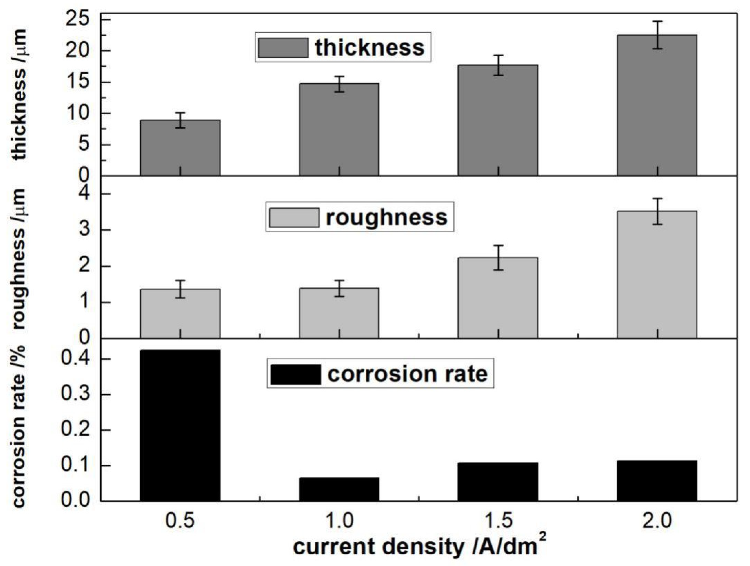
In addition to the electrolyte compositions, the current density is another important factor that influenced the properties of anodic coatings [12]. The anodizing processes were operated with the current density of 0.5, 1, 1.5, and 2 A·dm−2. As seen from Figure 3, the coating thickness and roughness increases with an increase of current density. The intensity of spark discharge increased with an increase of current density during the PEO process, which was beneficial to the growth of anodic coatings. Normally, after the anodizing process, the surface of the anodic coating generates many micropores and microcracks, which leads to an increase in surface roughness. The micropores are formed due to the spark discharge at the surface of Mg alloy, and the microcracks are caused by the rapid solidification of molten oxides by the cool electrolyte. With the increase of current density, both the discharge energy and volume of the molten oxide in the specific discharge channel increased, which led to an increase of surface roughness. Generally, the increase in coating thickness is beneficial to corrosion resistance, while the increase in roughness is detrimental to corrosion resistance. Hence, an appropriate current density applied to the PEO process can balance the contribution of film thickness and roughness on corrosion resistance. As obtained from Figure 3, the corrosion rate decreases when the current density is in the range of 0.5–1 A/dm2. It is noted that the corrosion rate increases with the further increase of current density. Hence, it is concluded that the optimal current density is 1 A/dm2.

3.2.2. Pulse Frequency

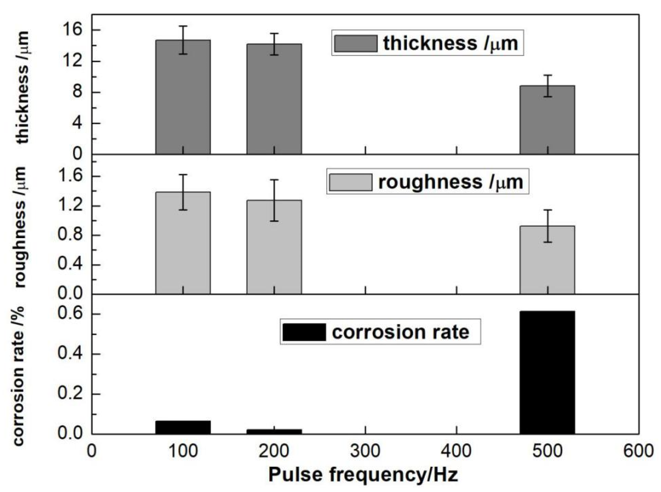
As we know, the growth of PEO coatings is accompanied by the discharging/cooling phenomenon. In addition, the formation of the discharge channel and the transfer of the electrolytic anions depend greatly on the electric field. In addition, the discharging and cooling times are dependent on the time of power on and off. Therefore, the pulse frequency has an important influence on the growth and performance of the PEO film. The trend of film thickness, roughness and corrosion rate with frequency is shown in Figure 4. It is observed that the thickness and roughness both decrease with the increase of the pulse frequency. The main reason is that as the frequency increases, the number of discharges in a pulse period decreases, so the temperature and pressure in the discharge channel of the anode surface decrease, and the material melted and sputtered decreases accordingly [42].
As seen from Figure 4, it is observed that the value of corrosion rate is 0.022 at 200 Hz, which is lower than that at 100 Hz and 500 Hz. Generally, in order to obtain good corrosion resistance of the film, the number of micropores and the size of the pore diameter should be reduced as much as possible at the same time. In addition, the contact between the corrosive medium and the alloy should be prevented as much as possible. Under the same conditions of other electrical parameters, the total energy passing through the sample surface remains the same. In this frame, the number of pulses per unit time increases with an increase of the pulse frequency, accompanied by the decrease of energy of a single pulse, which causes the number of micropores to change in opposite directions against the pore size. Thus, the proper pulse frequency is 200 Hz. This result is the combined effect of the number of pores and the size of the pores.

3.2.3. Duty Cycle

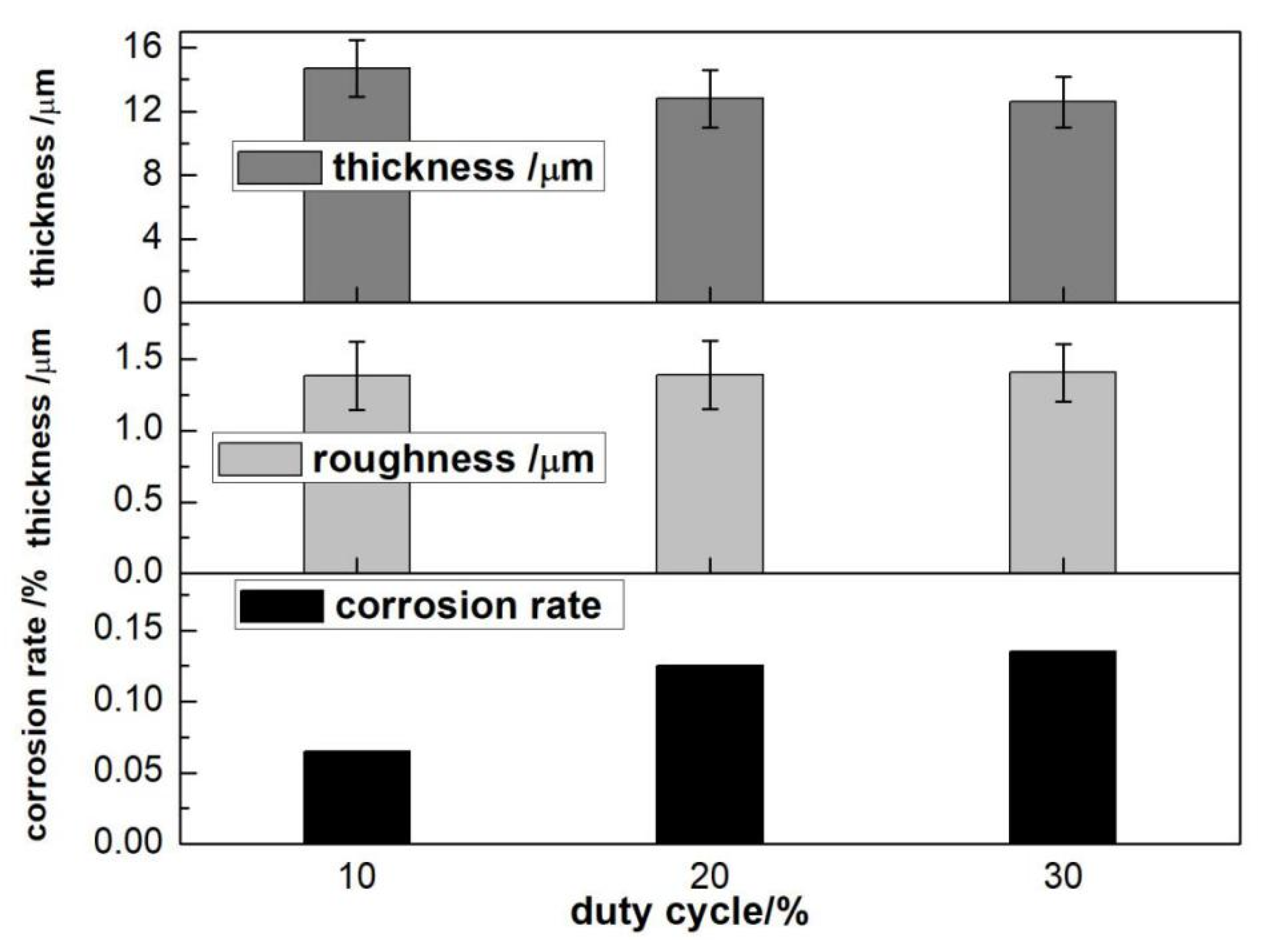
It is observed from Figure 5, that as the duty cycle increases, the thickness of the oxide film decreases, and the roughness slightly increases. At the same time, it is also found that the corrosion resistance decreases as the duty cycle decreases. This is due to the decrease in film thickness and increase in roughness, both of which will lead to a decrease in corrosion resistance. The duty cycle affects the duration of a single pulse discharge and the energy of the spark discharge. A high duty cycle will cause excessive discharge energy, and more oxide film will be melted and sprayed out through the discharge channel, resulting in the enlargement of discharge hole. Moreover, excessive accumulation of the ejected melt will increase the surface roughness of the oxide film, so its corrosion resistance will be reduced.

3.2.4. Oxidation Time

As seen from Figure 6, with the increase of oxidation time, the thickness of the PEO coatings gradually increases. In addition, when the oxidation time exceeds 10 min, the growth trend slows down. Meanwhile, it is obtained that the roughness of the film gradually increases with the extension of the oxidation time. Moreover, when the oxidation time exceeds 15 min, the roughness of the film remarkably increases. This is probably due to the introduction of the arc discharge stage of the PEO process. In this stage, the vent holes generated by the arc discharge increase, which promotes the increase of molten material ejected from the vent holes. This phenomenon leads to the increase of surface roughness. It can be also found that the corrosion rate firstly decreases with increase of the oxidation time, and then decreases with the extension of the oxidation time. When the oxidation time is 15 min, the corrosion rate of the prepared oxide film is the smallest. Thus, it is concluded that the optimal oxidation time is 15 min.

3.3. Morphology and Phase Analysis

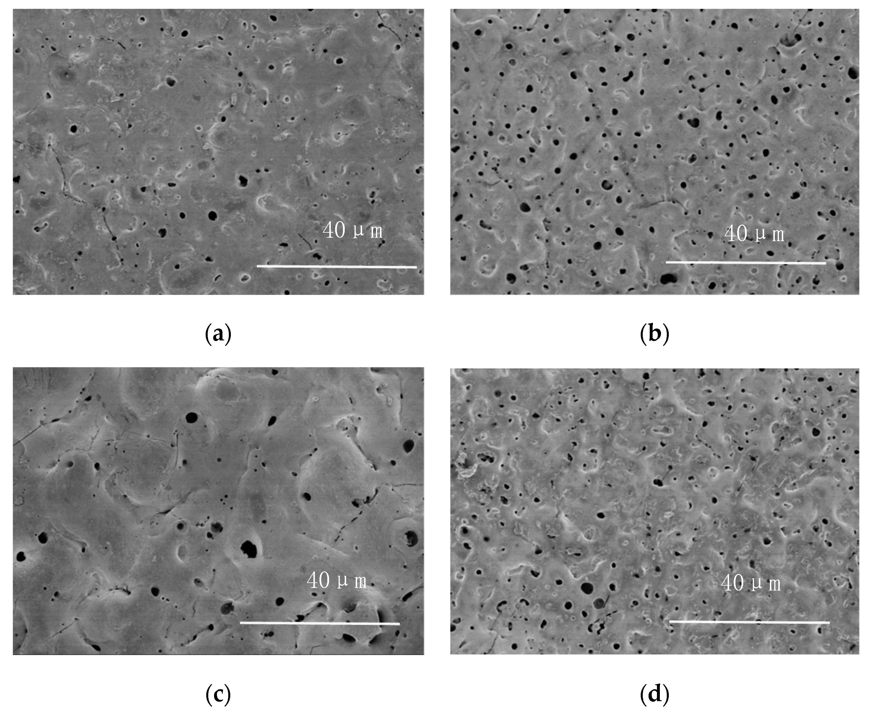
Figure 7 depicts the morphologies of the PEO coatings obtained with optimal conditions, test 3, test 4 and test 5. As seen from Figure 7, the micropores and cracks can be observed on the surface of all samples. It is noted that the surface of PEO coating with less micropores and cracks in Figure 7a is uniform and compact, compared with that of test 3, test 4 and test 5. This surface morphology promotes improvement of the corrosion resistance of the PEO coatings, as mentioned above. As seen in the PEO coating obtained by test 4 in Figure 7c, the diameter of the micropores increased significantly, as well as the cracks. As we know, the formation of micropore and cracks is due to gas release from discharge channels and thermal stress, respectively, which leads to a reduction of corrosion resistance. Furthermore, corrosive chloride ions can easily reach the surface of magnesium alloy substrates through large-diameter micropores. In cases test 3 and test 5 in Figure 7b,d, the diameters of micropores decreased compared with that of test 4, indicating the improvement of the surface structure.
Figure 8 shows the XRD patterns of the PEO coatings obtained under optimal conditions, test 3, test 4 and test 5. As seen from Figure 8, the phase compositions of PEO coatings are almost the same including MgO and Mg2SiO4. During the PEO process, the Mg ions dissolves from the substrate and reacts with oxygen ions at the solid–liquid interface of the magnesium anode to from the MgO. Meanwhile, the Mg2SiO4 is formed under the conditions of high temperature during sparking with the presence of Na2SiO3. This indicates that the phase compositions of the oxide coating is determined by the compositions of the electrolyte.

3.4. Electrochemical Performance

The corrosion resistance performances of anodic-coated and bare AZ31B Mg alloy were tested by potentiodynamic polarization in 3.5 wt% NaCl solution. The parameters of corrosion potential (Ecorr), corrosion current density (jcorr) and anodic (βa) and cathodic (βc) Tafel slopes are extracted directly from the potentiodynamic polarization curves displayed in Figure 9. The polarization resistances (Rp) are calculated from the equation.
R p = β a β b 2.303 j corr ( β a + β b )
The corrosion potential, corrosion current density and polarization resistances obtained from the Tafel curves are commonly used to evaluate the corrosion resistance of Mg alloy and its coating. A higher polarization resistance, lower corrosion current density and more positive corrosion potential often represent better corrosion resistance. Based on the orthogonal tests and the electrical parameters optimization experiment, it is obtained that optimal PEO anodized conditions are as follows: electrolyte compositions of 45 g/L NaOH, 50 g/L Na2SiO3 and 90 g/L Na2B4O7 with electric parameters of current density 1 A/dm2; pulse frequency 100 Hz; duty cycle 10% and oxidation time 15 min. Hence, the PEO obtained by the optimal conditions and orthogonal test 3, 4 and 5 were selected for potentiodynamic polarization tests to further investigate the electrochemical properties, as the corrosion resistance was better compared with that of other orthogonal tests. As can been seen from Figure 9 and Table 5, the Ecorr, jcorr and Rp of the bare AZ31B Mg alloy are −1.55 V, 2.88 × 10⁵ A/cm2, and 883 Ω·cm2, respectively. In terms of the anodic coating formed in the PEO electrolyte, the electrochemical performance has been greatly improved. Furthermore, it was found that the Ecorr, jcorr and Rp of PEO coating obtained in optimal conditions are −1.44 V, 1.98 × 10⁻⁷ A/cm2 and 196,699 Ω·cm2, respectively. These values are close to that obtained in test 5. It is noted that the difference between test 5 and optimal conditions represent only the pulse frequency. In addition, the PEO coating obtained by test 5 exhibits the better electrochemical performance, compared with the PEO coatings obtained by tests 4 and 3. This is consistent with the results of orthogonal experiments.

4. Conclusions

  • The four-factor and three-level orthogonal experiments were applied. It was observed that the coating thickness was significantly affected by NaOH, while Na2SiO3 had the greatest impact on corrosion resistance of the oxide coating. The orthogonal tests showed that the optimal formulation of the electrolyte was NaOH 45 g/L, Na2SiO3 50 g/L and Na2B4O7 90 g/L.
  • The optimal electrical parameter process was represented by current density 1 A/dm2, oxidation time 15 min, pulse frequency 200 Hz, and duty cycle 10%.
  • The surface of the PEO coating obtained by the optimal condition is uniform and compact. The XRD results revealed that the phase compositions of PEO coatings were almost the same including MgO and Mg2SiO4.
  • Potentiodynamic polarization behavior showed that the corrosion resistance of Mg alloy was greatly improved by PEO, and the electrochemical performances of the PEO coatings were the same as that of the orthogonal tests.

Author Contributions

Conceptualization, X.T. and J.L.; Formal Analysis, X.T., C.M., Y.X. and J.L.; Investigation, S.P., Y.Z., R.F., C.M. and J.Y.; Resources, X.T. and Y.X.; Writing–Original Draft Preparation, X.T.; Writing–Review and Editing, X.T.; Funding Acquisition, X.T. All authors have read and agreed to the published version of the manuscript.

Funding

This research was supported by Zhejiang Provincial Natural Science Foundation of China under Grant No. LY16E010003 and SRT innovation project of Jiaxing University under Grant No. CD8517211361.

Institutional Review Board Statement

Not applicable.

Informed Consent Statement

Not applicable.

Data Availability Statement

Not applicable.

Conflicts of Interest

The authors declare no conflict of interest.

References

  1. Kamil, M.; Kaseem, M.; Lee, Y.; Ko, Y. Microstructural characteristics of oxide layer formed by plasma electrolytic oxidation: Nanocrystalline and amorphous structures. J. Alloys Compd. 2017, 707, 167–171. [Google Scholar] [CrossRef]
  2. Cao, F.; Song, G.; Atrens, A. Corrosion and passivation of magnesium alloys. Corros. Sci. 2016, 111, 835–845. [Google Scholar] [CrossRef] [Green Version]
  3. Barbosa, P.B.; Knorchild, G. Anodization of Mg-alloy AZ91 in NaOH solutions. Surf. Coat. Technol. 2009, 203, 1629–1636. [Google Scholar] [CrossRef]
  4. Gray, X.; Luan, B. Protective coatings on magnesium and its alloys—A critical review. J. Alloys Compd. 2002, 336, 88–113. [Google Scholar] [CrossRef]
  5. Zhang, X.; Zhang, M.; Li, R.; Feng, X.; Pang, X.; Rao, J.; Cong, D.; Yin, C.; Zhang, Y. Active corrosion protection of Mg–Al layered double hydroxide for magnesium alloys: A Short Review. Coatings 2021, 11, 1316. [Google Scholar] [CrossRef]
  6. Dziková, J.; Fintová, S.; Kajánek, D.; Florková, Z.; Wasserbauer, J.; Doležal, P. Characterization and Corrosion Properties of Fluoride Conversion Coating Prepared on AZ31 Magnesium Alloy. Coatings 2021, 11, 675. [Google Scholar] [CrossRef]
  7. Baloch, A.; Kannan, M.B. Electropolymerisation of aniline on AZ91 magnesium alloy: The effect of coating electrolyte corrosiveness. Metals 2017, 7, 533. [Google Scholar] [CrossRef] [Green Version]
  8. Song, G. An irreversible dipping sealing technique for anodized ZE41 Mg alloy. Surf. Coat. Technol. 2009, 203, 3618–3625. [Google Scholar] [CrossRef]
  9. Dou, J.; Wang, J.; Li, H.; Lu, Y.; Yu, H.; Chen, C. Enhanced corrosion resistance of magnesium alloy by plasma electrolytic oxidation plus hydrothermal treatment. Surf. Coat. Technol. 2022, 424, 127662. [Google Scholar] [CrossRef]
  10. Evangelides, H.A. Method of Electrolytically Coating Magnesium and Electrolyte Therefore. U.S. Patent 2723952, 15 November 1955. [Google Scholar]
  11. Dow Chemical Co. Bath for and Method of Producing a Corrosion Resistant Coating upon Light Metals. GB Patent 762195, 28 November 1956. [Google Scholar]
  12. Shi, Z.; Song, G.; Atrens, A. Influence of anodising current on the corrosion resistance of anodised AZ91D magnesium alloy. Corros. Sci. 2006, 48, 1939–1959. [Google Scholar] [CrossRef]
  13. Wu, X.; Su, P.; Jiang, Z.; Meng, S. Influences of current density on tribological characteristics of ceramic coatings on ZK60 Mg alloy by plasma electrolytic oxidation. ACS Appl. Mater. Interfaces 2010, 3, 808–812. [Google Scholar]
  14. Rapheal, G.; Kumar, S.; Scharnagl, N.; Blawert, C. Effect of current density on the microstructure and corrosion properties of plasma electrolytic oxidation (PEO) coatings on AM50 Mg alloy produced in an electrolyte containing clay additives. Surf. Coat. Technol. 2016, 289, 150–164. [Google Scholar] [CrossRef]
  15. Wang, Q.; Lv, W.; Chen, J.; Lu, S. Characterization of ceramic coating on ZK60 magnesium alloyprepared in a dual electrolyte system by micro-arc oxidation. Rare. Met. 2013, 32, 459–464. [Google Scholar] [CrossRef]
  16. Choi, Y.; Salman, S.; Kuroda, K.; Okido, M. Improvement in corrosion characteristics of AZ31 Mg alloy by square pulse anodizing between transpassive and active regions. Corros. Sci. 2012, 63, 5–11. [Google Scholar] [CrossRef]
  17. Keyvani, A.; Zamani, M.; Bahamirian, M.; Nikoomanzari, E.; Fattah-alhosseini, A.; Sinad, H. Role of incorporation of ZnO nanoparticles on corrosion behavior of ceramic coatings developed on AZ31 magnesium alloy by plasma electrolytic oxidation technique. Surf. Interfaces 2021, 22, 100728. [Google Scholar] [CrossRef]
  18. Guo, Y.; Rogov, A.; Hird, A.; Mingo, B.; Matthews, A.; Yerokhin, A. Plasma electrolytic oxidation of magnesium by sawtooth pulse current. Surf. Coat. Technol. 2022, 429, 127938. [Google Scholar] [CrossRef]
  19. Baghdadabad, D.; Baghdadabad, A.; Khoei, S. Characterization of bioactive ceramic coatings synthesized by plasma electrolyte oxidation on AZ31 magnesium alloy having different Na2SiO3·9H2O concentrations. Mater. Today Commun. 2020, 25, 101642. [Google Scholar] [CrossRef]
  20. Ballam, L.R.; Arab, H.; Bestetti, M.; Franz, S.; Masi, G.; Sola, R.; Donati, L.; Martini, C. Improving the corrosion resistance of wrought ZM21 magnesium alloys by plasma electrolytic oxidation and powder coating. Materials 2021, 14, 2268. [Google Scholar] [CrossRef]
  21. Hwang, D.; Kim, Y.; Park, D.; Yoo, B.; Shin, D. Corrosion resistance of oxide layers formed on AZ91 Mg alloy in KMnO4 electrolyte by plasma electrolytic oxidation. Electrochim. Acta 2009, 54, 5479–5485. [Google Scholar] [CrossRef]
  22. Barchiche, C.; Rocca, E.; Juers, C.; Hazan, J.; Steinmetz, J. Corrosion resistance of plasma-anodized AZ91D magnesium alloy by electrochemical methods. Electrochim. Acta 2007, 53, 417–425. [Google Scholar] [CrossRef]
  23. Barchiche, C.; Veys-Renaux, D.; Rocca, E. A better understanding of PEO on Mg alloys by using a simple galvanostatic electrical regime in a KOH-KF-Na3PO4 electrolyte. Surf. Coat. Technol. 2011, 205, 4243–4248. [Google Scholar] [CrossRef]
  24. Lamaka, S.; Knorchild, G.; Snihirova, D.; Taryba, M.; Zheludkevich, M.; Ferreira, M. Complex anticorrosion coating for ZK30 magnesium alloy. Electrochim. Acta 2009, 55, 131–141. [Google Scholar] [CrossRef]
  25. Say, W.; Chen, C.; Hsieh, S. Electrochemical characterization of non-chromate surface treatments on AZ80 magnesium. Mater. Charact. 2008, 59, 1400–1406. [Google Scholar] [CrossRef]
  26. Yoo, B.; Shin, K.; Hwang, D.; Dong, H.; Dong, H. Effect of surface roughness on leakage current and corrosion resistance of oxide layer on AZ91 Mg alloy prepared by plasma electrolytic oxidation. Appl. Surf. Sci. 2010, 256, 6667–6672. [Google Scholar] [CrossRef]
  27. Guo, H.; An, M.; Huo, H.; Xu, S.; Wu, L. Microstructure characteristic of ceramic coatings fabricated on magnesium alloys by micro-arc oxidation in alkaline silicate solutions. Appl. Surf. Sci. 2006, 252, 7911–7916. [Google Scholar] [CrossRef]
  28. Hsiao, H.; Tsung, H.; Tsai, W. Anodization of AZ91D magnesium alloy in silicate-containing electrolytes. Surf. Coat. Technol. 2005, 199, 127–134. [Google Scholar] [CrossRef]
  29. Wu, H.; Cheng, Y.; Li, L.; Chen, Z.; Wang, H.; Zhang, Z. The anodization of ZK60 magnesium alloy in alkaline solution containing silicate and the corrosion properties of the anodized films. Appl. Surf. Sci. 2007, 253, 9387–9394. [Google Scholar] [CrossRef]
  30. Li, Z.; Yuan, Y.; Jing, X. Comparison of plasma electrolytic oxidation coatings on Mg-Li alloy formed in molybdate/silicate and aluminates/silicate composite electrolytes. Mater. Corros. 2014, 65, 493–501. [Google Scholar] [CrossRef]
  31. Simchen, F.; Sieber, M.; Kopp, A.; Lampke, T. Introduction to Plasma Electrolytic Oxidation—An Overview of the Process and Applications. Coatings 2020, 10, 628. [Google Scholar] [CrossRef]
  32. Arrabal, R.; Matykina, E.; Skeldon, P. Incorpocyclen of zirconia particles into coatings formed on magnesium by plasma electrolytic oxidation. J. Mater. Sci. 2008, 43, 1532–1538. [Google Scholar] [CrossRef]
  33. Lee, K.; Shin, K.; Namgung, S.; Yoo, B.; Shin, D. Electrochemical response of ZrO2-incorporated oxide layer on AZ91 Mg alloy processed by plasma electrolytic oxidation. Surf. Coat. Technol. 2011, 205, 3779–3784. [Google Scholar] [CrossRef]
  34. Mashtalyar, D.; Gnedenkov, S.; Sinebryukhov, S.; Imshinetskiy, I.; Puz, A. Plasma electrolytic oxidation of the magnesium alloy MA8 in electrolytes containing TiN nanoparticles. J. Mater. Sci. Technol. 2017, 33, 461–468. [Google Scholar] [CrossRef]
  35. Tu, X.; Miao, C.; Zhang, Y.; Xu, Y.; Li, J. Plasma electrolytic oxidation of magnesium alloy AZ31B in electrolyte containing Al2O3 sol as additives. Materials 2018, 11, 1618. [Google Scholar] [CrossRef] [PubMed] [Green Version]
  36. Tu, X.; Chen, L.; Wu, J. Effect of glucose on properties of anodizing film on AZ31B magnesium alloy. Chin J. Nonferr. Met. 2013, 23, 727–734. [Google Scholar]
  37. Fukuda, H.; Matsumoto, Y. Effects of Na2SiO3 on anodization of Mg-Al-Zn alloy in 3 M KOH solution. Corros. Sci. 2004, 46, 2135–2142. [Google Scholar] [CrossRef]
  38. Chai, L.; Yu, X.; Yang, Z.; Wang, Y.; Okido, M. Anodizing of magnesium alloy AZ31 in alkaline solutions with silicate under continuous sparking. Corros. Sci. 2008, 50, 3274–3279. [Google Scholar] [CrossRef]
  39. Qian, J.; Li, D.; Wang, X.; Guo, B. Effects of concentcyclen of sodium borate on anodizing for magnesium alloy. J. Chin. Soc. Corros. Prot. 2005, 25, 275–279. [Google Scholar]
  40. Gao, X.; Zhang, Y.; Zhang, H.; Wu, Q. Effects of machine tool configucyclen on its dynamics based on orthogonal experiment method. Chin. J. Aeronaut. 2012, 25, 285–291. [Google Scholar] [CrossRef] [Green Version]
  41. Guo, X.; An, M.; Yang, P.; Su, C. Effects of benzotriazole on anodized film formed on AZ31B magnesium alloy in environmental-friendly electrolyte. J. Alloys Compd. 2009, 482, 487–497. [Google Scholar] [CrossRef]
  42. Zou, B.; Lv, G.; Zhang, G.; Tian, Y. Effect of current frequency on properties of coating formed by microarc oxidation on AZ91D magnesium alloy. Trans. Nonferr. Met. Soc. China 2015, 25, 1500–1505. [Google Scholar] [CrossRef]
Figure 1. The film thickness of each test.
Coatings 12 00578 g001
Figure 2. The corrosion rate of each test.
Coatings 12 00578 g002
Figure 3. The values of corrosion rate, roughness and thickness at different current densities. Electrolyte compositions: 45 g/L NaOH, 50 g/L Na2SiO3, 90 g/L Na2B4O7. Electrical parameters: oxidation time 10 min; pulse frequency 100 Hz; duty cycle 10%.
Coatings 12 00578 g003
Figure 4. The values of corrosion rate, roughness and thickness at different pulse frequencies. Electrolyte compositions: 45 g/L NaOH, 50 g/L Na2SiO3, 90 g/L Na2B4O7. Electrical parameters: current density 1 A/dm2; oxidation time 10 min; duty cycle 10%.
Coatings 12 00578 g004
Figure 5. The values of corrosion rate, roughness and thickness at different duty cycles. Electrolyte compositions: 45 g/L NaOH, 50 g/L Na2SiO3, 90 g/L Na2B4O7. Electrical parameters: current density 1 A/dm2; oxidation time 10 min; pulse frequency 100 Hz.
Coatings 12 00578 g005
Figure 6. The values of corrosion rate, roughness and thickness at different oxidation time. Electrolyte compositions: 45 g/L NaOH, 50 g/L Na2SiO3, 90 g/L Na2B4O7. Electrical parameters: current density 1 A/dm2; pulse frequency 100 Hz; duty cycle 10%.
Coatings 12 00578 g006
Figure 7. SEM images of PEO coatings (a) optimal condition, (b) test 3, (c) test 4 and (d) test 5. Optimal conditions are: electrolyte compositions of 45 g/L NaOH, 50 g/L Na2SiO3 and 90 g/L Na2B4O7 with electric parameters of current density 1 A/dm2; pulse frequency 200 Hz; duty cycle 10% and oxidation time 15 min.
Coatings 12 00578 g007
Figure 8. XRD patterns of PEO coatings (a) optimal condition, (b) test 3, (c) test 4 and (d) test 5. Optimal conditions are: electrolyte compositions of 45 g/L NaOH, 50 g/L Na2SiO3 and 90 g/L Na2B4O7 with electric parameters of current density 1 A/dm2; pulse frequency 200 Hz; duty cycle 10% and oxidation time 15 min.
Coatings 12 00578 g008
Figure 9. Potentiodynamic polarization behavior of anodic-coated and bare AZ31B Mg alloy. Electrolyte compositions of 45 g/L NaOH, 50 g/L Na2SiO3 and 90 g/L Na2B4O7 for test 5, 30 g/L NaOH, 70 g/L Na2SiO3 and 90 g/L Na2B4O7 for test 3 and 45 g/L NaOH, 30 g/L Na2SiO3 70 g/L Na2B4O7. Optimal conditions are: electrolyte compositions of 45 g/L NaOH, 50 g/L Na2SiO3 and 90 g/L Na2B4O7 with electric parameters of current density 1 A/dm2; pulse frequency 200 Hz; duty cycle 10% and oxidation time 15 min.
Coatings 12 00578 g009
Table 1. Factors and levels of orthogonal test.
LevelsFactors
A
NaOH/g/L
B
Na2SiO3/g/L
C
Na2B4O7/g/L
1303050
2455070
3607090
Table 2. Electrical parameters and its levels.
Current Density/A·dm−2Oxidation Time/minPulse Frequency/HzDuty Cycle/%
0.5510010
1.01020020
1.51550030
2.020----
Table 3. Range analysis of orthogonal test with thickness as evaluation index.
Evaluation IndexH1H2H3h1h2h3RInfluence DegreeOptimal Formulation
Thickness/μmA48.244.133.516.114.711.24.9A > C > BA1B2C2
B41.443.341.113.814.413.70.7
C36.944.744.212.314.914.72.6
Table 4. Range analysis of orthogonal test with corrosion rate as evaluation index.
Evaluation IndexH1H2H3h1h2h3RInfluence DegreeOptimal Formulation
Corrosion rateA0.890.671.410.300.220.470.25B> C > AA2B2C3
B1.380.571.020.460.190.340.27
C1.430.880.660.480.290.220.26
Table 5. Electrochemical parameters related to potentiodynamic polarization curves for PEO coatings formed in various electrolytes and electric parameters.
SamplesEcorr (V)jcorr (A/cm2)βa (V/Decade)βc (V/Decade)Rp (Ω·cm2)
Bare Mg alloy substrate−1.552.88 × 1050.1230.112883
PEO coating of optimal condition−1.441.98 × 10−70.1840.175196,699
PEO coating of test 5−1.452.46 × 10−70.1890.225181,307
PEO coating of test 4−1.481.91 × 10−60.1260.0467161
PEO coating of test 3−1.507.57 × 10−70.1330.04117,976
Publisher’s Note: MDPI stays neutral with regard to jurisdictional claims in published maps and institutional affiliations.