Abstract
Deep and narrow groove structures are widely used in aviation, aerospace, weapons, and other industries, and play a very important role. In order to solve the problems of machining tool deformation, machining flying edge, burr in traditional Computerized Numerical Control (CNC) milling for deep and narrow grooves, and the problems of serious motor loss and low machining efficiency in non-contact electrical discharge machining (EDM), electrochemical mask machining through the mask treatment of the non-processed part mask processing, and with no loss of the processing cathode tool, was suggested as an efficient way to solve these problems. Considering that the corrosion removal of the anodic workpiece is mainly subject to the multi-physical field coupling action between the electric field, the flow field, and the temperature field, it is necessary to construct a multi-physical field coupling model of electrochemical mask machining and combine this with the numerical simulation analysis to realize the distribution state of the multi-physical field, so as to realize the optimization guidance of the overall processing process.
1. Introduction
Deep and narrow groove structures are widely used in aviation, aerospace, weapons, and other industries, and play a very important role. These deep and narrow groove structures require not only smaller width sizes, but also a large and deep aspect ratio [1]. To achieve the production of such complex small-size structures, on the one hand, KH Oh. took the lead in combining laser processing and wet etching technology to achieve the efficient processing of the deep narrow groove structure (the groove is 50 μm wide, 150 μm deep, and 50 mm long) of an aero-engine micro-cooling tube group [2,3]. On the other hand, in order to improve the processing accuracy of the cooling groove of a rocket engine nozzle, Lei H et al. [4] used digital milling technology to realize the 784 cooling groove processing on a circular pipe with a depth of 2.6 mm in the group (the outer diameter of the rocket nozzle is 1500 mm and its axial height is 940 mm). Therefore, the current processing methods for the above deep narrow grooves mainly include traditional mechanical machining and non-traditional machining [5].
Traditional mechanical machining methods mainly include milling, drilling, cutting, tapping, grinding, etc. Because the machining operation is simple and adaptable, it is a common machining method, and for the deep and narrow groove structure, more machining methods are used for milling processing. In the milling process, the tool is an important factor affecting processing efficiency and processing precision. The heat in the machining process can cause tool deformation, causing machining error; secondly, milling machining is contact machining, therefore, the force applied can also cause deformation of the tool, which can also cause machining error. The tool surface roughness, material characteristics, and tool wear degree can all cause certain machining errors [6,7]. Many scholars have put forward the multi-milling method [8] and using a five-axis precision CNC milling machine [9,10] to realize high efficiency and machining. However, the milling and processing of deep narrow groove structures face an inevitable problem, which is that the edge and bottom of the groove will have residues, such as flying edge, burr, and so on, that are difficult to remove, especially when processing nickel-based high-temperature alloys and titanium alloys where the phenomenon of residue is more obvious. Therefore, the application of milling technology in titanium alloys is restricted [11,12,13]. To solve the above narrow groove processing problem for hard cutting alloys, non-traditional machining is introduced. While in the process of deep narrow groove electro-spark forming, with an increase in the processing depth, the concentration of electro-corrosion products and the working liquid temperature in the processing gap gradually increase. If the working liquid environment can not be well improved, the stability and processing efficiency of the electro-spark processing process will be seriously affected [14]. Then, the problems of low processing efficiency, serious electrode loss, and high processing costs make this technology unable to be used in a field with high precision requirements and less material removal [15]. With the development of the times, based on the principle of the above electro-spark forming, Soviet scientists proposed electric-spark line cutting processing technology. Electric-spark line cutting technology, with its good flexibility, a wide range of applicable materials, high processing efficiency, and very good processing precision, has been widely used in national defense, medical treatment, and other industrial fields, and is especially suitable for the processing of narrow grooves and narrow joints of parts. However, its application to large shape sizes, blind cavities, and blind grooves has certain limitations [16]. Compared with electro-spark forming processing technology, electrochemical machining technology is also copied by the forming cathode in this study. In contrast, electrochemical machining is used to realize the dissolution and removal of workpiece materials through the redox reaction between the cathode and anticathode, so as to achieve the purpose of forming and processing. This processing method is especially applicable to high-strength and high hardness materials that are difficult to process in the traditional mechanical machining methods. On the basis of theory, electrochemical mask machining is a special method of contactless electrochemical machining, through which the anode workpiece does not process part of the insulation mask. Using electrochemical machining between the electrode liquid in the electrode field of the anode, not the mask field, electrolyte flow field and temperature field coupling realizes the anode material and cathode hydrogen with low cost, efficient processing (as shown in Figure 1). Considering that the corrosion removal of the anodic workpiece is mainly subject to the multi-physical field coupling action between the electric field, the flow field, and the temperature field, it is necessary to construct a multi-physical field coupling model of electrochemical mask machining and combine this with numerical simulation analysis to realize the distribution state of the multi-physical field, so as to realize the optimization guidance of the overall processing process. If a very good grasp of the influence of the process can be achieved, the processed parts can achieve high size precision and surface quality, and also inspire scholars to explore the process and the scientific research results of the production in practice [17,18]. In order to solve the problem of short circuits caused by the flow field instability in the electrochemical machining of the array of deep narrow grooves, Liu et al. studied the influence law of the cathode superimposed low-frequency vibration on the flow field through numerical simulation and analysis of the flow field, and the one-time processing of 30 deep narrow groove structures was realized [19]. Silva et al. studied the influence law of the inter-relationship between electrolyte conductivity and process parameters on the processing precision of narrow groove and narrow seam, and established and analyzed a mathematical model of processing surface-forming law, and a circular array narrow groove structure that meets the requirements was processed through a process test [20]. Meanwhile, Zhao et al. found that for a razor net cover with an outer circle of 90 and an inner circle of 45 deep, narrow groove structure processing proved to be a difficult problem. However, using a forming tool cathode, through electric field stimulation, flow field simulation, cathode feed mode, processing the groove width of 0.27 ± 0.02 mm and a wall thickness is 0.4–0.6 mm, gave a better consistency of deep narrow groove structure, and this was successfully used in enterprising mass production [21]. Although narrow-groove electrochemical machining technology has good application prospects, most of the research is still in the early exploration stage and less applied in production practice. This is mainly because there are many above-discussed factors affecting the electrochemical machining process, and mastering the influence law of these factors on the processing process is not comprehensive enough.
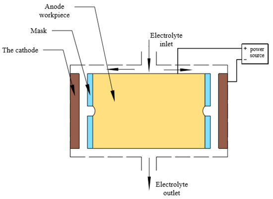
Figure 1.
Schematic diagram of mask electrochemical machining of annular narrow groove.
In order to ensure processing efficiency, the electrochemical processing stability of the slot workpiece was studied [22,23,24,25]. In this paper, a mathematical model of the electric field, flow field, and temperature field coupling is established by means of mask electrochemical machining, and the above model is numerically simulated based on COMSOL Multiphysics. The variation law of each parameter in the machining process is also analyzed. According to the simulation result, the feasibility of the mask electrolytic machining of the annular narrow groove is verified, the ring groove process parameters are obtained, and the slotting precision and the surface quality are improved, therefore, a new method and a theoretical foundation are provided for the in-depth study of the electrolytic processing of the complex special-shaped cavity.
2. Theoretical Analysis of Mask Electrochemical Machining
2.1. The Principle of Mask Electrolysis
The principle of the mask electrolytic machining ring cell is shown in Figure 1. Mask insulation, anodic workpiece exposed area, and electrolyte contact follow Faraday’s law and continue to dissolve until etched to meet the requirements of the shape [26,27].
2.2. Forming Law of Mask Electrochemical Machining
In the process of mask electrolytic machining, the surface shape and size of the cathode will not change when the cathode is fixed. As shown in Figure 2, the initial gap between the anode workpiece and the cathode is . After t time, the depth of the machining slot is H.
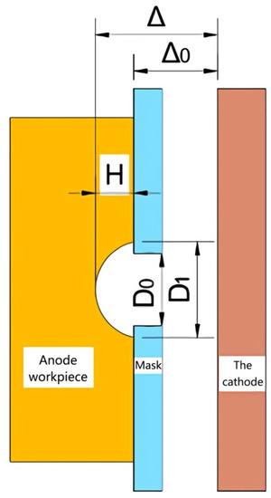
Figure 2.
Schematic diagram of the position of the mask electrochemical machining.
After calculation, the depth of the ring groove H after the mask electrochemical machining time t is given in Equation (2) [28]:
In the process of an electrochemical reaction, the distribution of the electric field, flow field, and temperature field in the gap between electrodes is very complex, and its parameters interact with each other and change at all times, which makes it difficult to predict the anodic dissolution characteristics accurately. Therefore, it is necessary to simulate the multi-physical field coupling numerical simulation of the mask electrolytic machining process.
3. Methodology
3.1. Establishment of Geometric Model
The object of processing in this paper is the circular groove in the winding wheel, the overall structure of which is shown in Figure 3a, and the narrow groove structure and enlarged figure are shown in Figure 3b.
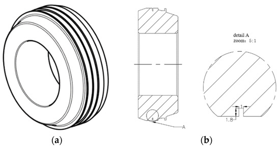
Figure 3.
Annular narrow slot geometric model. (a) Integral structure of winding wheel; (b) Narrow slot structure and magnification diagram.
The three-dimensional section view of the electrochemical machining model of the ring groove mask is shown in Figure 4a. Since the whole model is annular, it is assumed that the coupling field in each section is the same. In order to facilitate analysis and calculation, the model is simplified into two dimensions. The red border of the interpolar gap in Figure 4a is taken for analysis. The two-dimensional mathematical model is shown in Figure 4b, where L2, L3 is the free boundary of the machining gap, L1 is the cathode boundary, L6 is the anode workpiece boundary, L4, L5, L7, L8 is the insulation boundary.
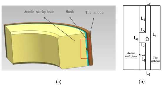
Figure 4.
Machining area model of ring groove. (a) Three-dimensional model of ring groove machining; (b) Two-dimensional mathematical model.
3.2. Multi-Physical Field Coupling Analysis
The electrochemical machining process of a ring cell and its complexity involve flow field, electric field, temperature field, and structural field, which vary and affect each other at any time [29].
The flow field and electric field affect the conductivity and current efficiency, and the conductivity increases with the increase in temperature, which leads to the change in workpiece erosion rate and then affects the distribution of the electric field and flow field [30,31]. The electric field model (Equation (2)) and the flow field model (Equation (3)) are substituted into the current density Equation (4) to obtain the coupling Equation (5) of the flow field and the electric field [32,33,34]:
4. Numerical Simulation Analysis
The parameters of the processing area are a groove width of 1mm, the depth of the groove is 1.8 mm, the thickness of the mask is 0.1 mm, the selection quality of the electrolyte is 10% NaNO3 solution [35].
Then, add current density, turbulence, fluid heat transfer, moving grid physical field to COMSOL Multiphysics. In the current density field, the grid is divided (in order to ensure the simulation accuracy, the tetrahedral mesh is needed and the refinement mesh size is 0.4 and the corresponding number of cells is 183,581). Meanwhile, the boundary conditions are adjusted (the inlet pressure is 0.19–0.25 Mpa, the processing gap is 0.1–0.5 mm, and the processing voltage is 8–30 V), and the single-field and the coupling field are simulated by changing the different processing parameters.
4.1. The Influence Law of Process Parameters at the Initial Moment
Under different electrolyte inlet pressures, the flow velocity distribution cloud diagram at the machining gap is shown in Figure 5. With the increase in electrolyte flow rate, the streamline distribution is similar, but the flow rate increases gradually. The flow rate at the slot can reach 11 m/s, the streamline distribution is stable without liquid shortage, and the interpolar products can be taken away in time to ensure stable processing. The temperature distribution in the machining gap under different inlet pressures is shown in Figure 6. The heat generated by the current heats up the electrolyte, the inlet pressure increases, and the interelectrode velocity increases. In order to ensure the uniformity of the flow field, a large electrolyte inlet pressure is used in the machining, but too much pressure makes the flow rate too large, resulting in a tremor affecting the machining accuracy. When the inlet pressure of the electrolyte is 0.23 Mpa, the flow rate between the electrodes is 10.27 m/s, which can meet the processing requirements.
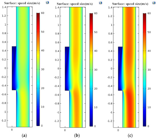
Figure 5.
Velocity between poles under different inlet pressures. (a) 0.20 Mpa; (b) 0.23 Mpa; (c) 0.25 Mpa.
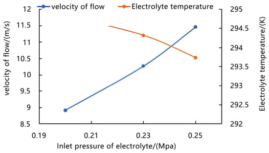
Figure 6.
Variation trend of interpolar flow rate and electrolyte temperature.
As shown in Figure 7, the initial current density around the machining area increases with the decrease in the machining gap, while the current density of the slotted part is basically the same distribution of unit current density under different gaps. Therefore, different machining gaps mainly affect the initial current density distribution at the gap between the anode and cathode, with little difference in the influence on the slotted area. However, too much machining gap can affect the current distribution, weaken the interelectrode electric field, give small clearance for machining electrode current density distribution of the uniform, and can promote ring groove shape precision on the basis of the machining efficiency but if the gap is too small, it is easy to cause short-circuit burns and creates cathode electrolytic product discharge difficulties, so this article chooses an initial machining gap of 0.2 mm.
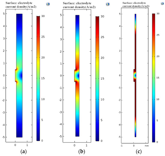
Figure 7.
Current density cloud map corresponding to different processing gaps. (a) Machining gap 0.5 mm; (b) Machining gap 0.2 mm; (c) Machining gap 0.1 mm.
4.2. Simulation Analysis of Ring Groove Forming Process
(1). Effect of machining time and voltage on groove depth: On the basis of the above electric field and the coupling simulation of the flow field, the physical field of the moving mesh is added, and the change of the depth of the groove under different machining voltage and processing times is solved by the transient solver, and the variation rule, shown in Figure 8, is obtained by numerical fitting.
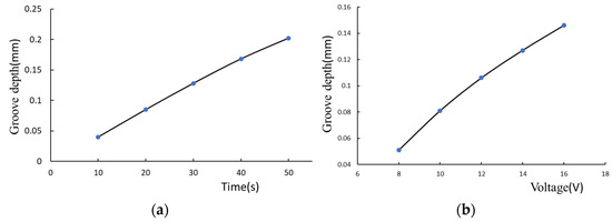
Figure 8.
Slot depth variation diagram. (a) The relationship between the depth of the slot and the processing time (15 V); (b) The relationship between the depth of the slot and the processing time (30 V).
As shown in Figure 8a, as the processing time increases, the depth of the groove deepens, but the growth rate decreases. This is mainly due to the anodic material removal, the interelectrode machining gap becomes larger, and the interelectrode current density decreases under the condition that the processing voltage remains unchanged, leading to a decrease in processing efficiency. As shown in Figure 8b, due to the increase in voltage and conductivity, the depth of the slot increases but the increase in the current density of the machining gap is limited, which leads to the slow growth rate of the slot depth. It is found from the trend diagram that the growth rate of the slot depth is mainly related to the processing time and the inter-pole gap, and the voltage has little effect on it. A processing voltage of 12 V can provide a large interpolar current density to complete the machining of the ring slot and the stray corrosion of slot width can ensure the machining accuracy. Therefore, the processing voltage of 12 V is selected in this paper.
(2). Study on parameter distribution between poles: In that electrolytic process, the constant variation of the profile of the workpiece results in a change in the electric field structure and the electrical conductivity of the electrolyte. Through the multi-physical field coupling simulation, the current density distribution in the machining gap after processing for 120 s is obtained, as shown in Figure 9a, and the current density of the surface of the workpiece is gradually reduced as the processing is carried out, meaning the dissolution rate of the anode is reduced, and the processing erosion amount in the same time is reduced. The erosion rate in the deep direction of the groove becomes slow. Figure 9b shows the electrolyte potential distribution. The anode potential was higher and showed a uniform trend of decline. With the progress of the processing, the potential at the ring groove was higher and evenly distributed.
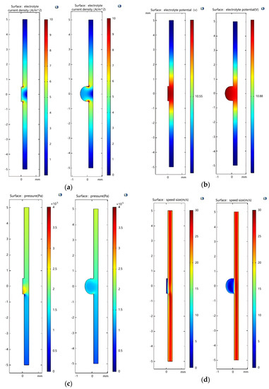
Figure 9.
Simulation comparison of different processing times. (a) Electrolyte current density; (b) electrolyte potential; (c) electrolyte pressure change; (d) electrolyte flow rate change.
In order to ensure the smooth progress of the mask electrolytic machining and the timely discharge of electrolytic products and heat, large electrolyte pressure and flow rate are needed at the machining gap. As shown in Figure 9c,d, the flow rate of the small electrolyte between the two poles is faster at the initial time of machining. With the removal of the anode workpiece, the gap between the large electrodes becomes larger with the removal of the anode workpiece because the constant inlet flow rate leads to a decrease in pressure and flow rate. Due to the continuous etching process, the gap between the anode and the cathode will become larger, the flow of the electrolyte in the deep groove will be blocked, the speed of the electrolyte will be slow, and the processing stability will be affected.
In the above, the COMSOL simulation software is used to simulate and study the variation rules of each physical field in the process of circular narrow groove machining under the conditions of multi-physical field coupling of electrochemical machining. According to the simulation results, the machining accuracy can be predicted and the actual electrochemical machining process of a circular groove can be guided to provide a guarantee for mass production of the workpiece.
5. Conclusions
With the advantage of the narrow groove of electrolytic mask machining, taking the electrolytic machining of an annular narrow groove as an example, by constructing the coupling action model between the electric field, flow field, and temperature field and using COMSOL numerical simulation analysis software, the mass erosion and process efficiency guidance under the coupling of multiple physical field parameters are realized, as follows:
(1.) It is known that the distribution of current density can be uniform with a small initial machining gap, and the product between electrodes can be taken away in time with large inlet pressure, which can improve the machining efficiency and ensure the accuracy of the ring slot at the same time;
(2.) In the process of the electrolytic machining of ring cells, the current density between electrodes is always evenly distributed. However, with the decrease in the depth current density of the ring slot, the erosion rate decreases, and the machining efficiency decreases;
(3.) The high electrolyte pressure and the flow rate can discharge the electrolytic product and heat in time, and as the inter-electrode gap of the etching is increased, the pressure and the speed of the electrolyte are reduced, and the processing stability can be affected.
By comparing the above findings with references [19,20,21] in the Introduction, it demonstrates that conclusions (1.) and (3.) above are similar to reference [20] (when using a narrow interelectrode gap (50 μm), size accuracy of ± 2 μm, surface finish of 0.01 μmRa, (50 μm) for small (100 mm2) parts), and [19] (using ordinary multi-slot ECM processing where most of the electrolyte is discharged from the channels between the cathode tools), respectively. In conclusion (2.), when the feed rate and the ablation rate change with the processing time, the electric field strength gradually decreases when the processing gap gradually increases, and finally leads to the ablation rate gradually decreasing with the processing time, which is not mentioned in previous studies (that is, the coupling of multiple physical fields and the interpolar structural fields). Through the multi-physical field coupling simulation analysis of annular narrow cell mask electrolytic machining, the process parameters are obtained as follows: initial machining gap 0.1 mm, electrolyte inlet pressure 0.23 Mpa, machining voltage 12 V. The results show that the multi-physical field coupling simulation is carried out on the mask electrolysis process of the annular narrow groove, and the variation rule of the interelectrode parameters can be obtained, and the machining process can be effectively predicted and the test period can be shortened.
Author Contributions
Conceptualization, R.Z. and L.H.; methodology, L.H. and Y.C.; validation, R.Z., L.H. and W.T.; formal analysis, R.Z. and L.H.; investigation, N.W. and H.Z.; resources, Y.C.; writing—original draft preparation, L.H. and R.Z.; writing—review and editing, L.H.; project administration, Y.C.; funding acquisition, Y.C. All authors have read and agreed to the published version of the manuscript.
Funding
This paper is supported by the project of the 2019 Yulin Science and Technology Program under Grant No. K20190176.
Institutional Review Board Statement
Not applicable.
Informed Consent Statement
Not applicable.
Data Availability Statement
Not applicable.
Conflicts of Interest
The authors declare that there are no conflicts of interest regarding the publication of this article.
References
- Bai, Y.Y.; Lu, M.; Li, W.B. Overview and expectation of research on narrow—deep—groove machining technology. Manuf. Technol. Mach. Tool 2014, 3, 45–49. [Google Scholar]
- Oh, K.H.; Lee, M.K.; Jeong, S.H. Laser micromachining of high-aspect-ratio metallic grooves for application to microthermal devices. J. Micromechanics Microengineering 2006, 16, 1958. [Google Scholar] [CrossRef]
- Oh, K.H.; Lee, M.K.; Kwon, S.J.; Jeong, S.H. Fabrication of high-aspect-ratio microgrooves with laser-assisted wet etching for micro heat pipe. In Proceedings of the Conference on Lasers and Electro-Optics and 2006 Quantum Electronics and Laser Science Conference, San Jose, CA, USA, 21–26 May 2006; pp. 1–2. [Google Scholar]
- Han, L.; He, W.D. Digitization process technology of cooling grooves on nozzle of liquid-propellant rocket engine. J. Rocket. Propuls. 2014, 40, 58–61. [Google Scholar]
- Zhang, C.; Guo, J.; Zhang, C.; Chen, X.; Liu, J.; Zhang, Y. Research on flow field of electrochemical milling on deep-narrow groove with tube electrode. Electromach. Mould. 2020, 31, 31–34. [Google Scholar]
- Su, C.; Hou, M.M.; Zhu, L.D.; Wang, W.S. SPH-based numerical simulation for big deformation during metal cutting. J. Northeast. Univ. Nat. Sci. 2009, 30, 419–421. [Google Scholar]
- Bao, J.; Li, L.; He, N.; Huang, L. A brief review of micronmilling technology. Mech. Sci. Technol. Aerosp. Eng. 2009, 28, 1019–1022. [Google Scholar]
- Pan, M.Q.; Li, J.H.; Tang, Y. Development of high-aspect-ratio microchannel heat exchanger based on multi-tool milling process. J. Cent. South Univ. Technol. 2008, 15, 228–234. [Google Scholar] [CrossRef]
- Bang, Y.B.; Lee, K.M.; Oh, S. 5-axis micro milling machine for machining micro parts. Int. J. Adv. Manuf. Technol. 2005, 25, 888–894. [Google Scholar] [CrossRef]
- Shamoto, E.; Saito, A. A novel deep groove machining method utilizing variable-pitch end mill with feed-directional thin support. Precis. Eng. 2016, 43, 277–284. [Google Scholar] [CrossRef]
- Niknam, S.A.; Songmene, V. Analysis of friction and burr formation in slot milling. Cirp Conf. Manuf. Syst. 2014, 21, 755–759. [Google Scholar] [CrossRef]
- Niknam, S.A.; Songmene, V. Factors governing burr formation during high-speed slot milling of wrought aluminum alloys. Proc. Inst. Mech. Eng. Part B J. Eng. Manuf. 2013, 227, 1165–1179. [Google Scholar] [CrossRef]
- Li, A.; Zhao, J.; Zhou, Y.; Chen, X.; Wang, D. Experimental investigation on chip morphologies in high-speed dry milling of titanium alloy Ti-6Al-4V. Int. J. Adv. Manuf. Technol. 2012, 62, 933–942. [Google Scholar] [CrossRef]
- Klocke, F.; Holsten, M.; Welling, D.; Klink, A.; Perez, R. Influence of threshold based process control on sinking EDM of a high aspect ratio geometry in a gamma titanium aluminide. Procedia Cirp 2015, 35, 73–78. [Google Scholar] [CrossRef][Green Version]
- Abbas, N.M.; Solomon, D.G.; Bahari, M.F. A review on current research trends in electrical discharge machining (EDM). Int. J. Mach. Tools Manuf. 2007, 47, 1214–1228. [Google Scholar] [CrossRef]
- Sarkar, S.; Mitra, S.; Bhattacharyya, B. Parametric optimisation of wire electrical discharge machining of γ titanium aluminide alloy through an artificial neural network model. Int. J. Adv. Manuf. Technol. 2006, 27, 501–508. [Google Scholar] [CrossRef]
- Zhu, Y.W.; Xu, J.W. The basic application study on electrochemical machining integral impeller with big-twisted blades. Int. Technol. Innov. Conf. 2006, 7, 587–593. [Google Scholar]
- Mahdavinejad, R.; Hatami, M. On the application of electrochemical machining for inner surface polishing of gun barrel chamber. J. Mater. Processing Technol. 2008, 202, 307–315. [Google Scholar] [CrossRef]
- Liu, J.; Jiang, X.C.; Zhui, D. Electrochemical machining of multiple slots with low-frequency tool vibrations. Procedia Cirp 2016, 42, 799–803. [Google Scholar]
- Silva, A.K.M.D.; Altena, H.S.J.; Mcgeough, J.A. Influence of electrolyte concentration on copying accuracy of precision-ECM. CIRP Ann.-Manuf. Technol. 2003, 52, 165–168. [Google Scholar] [CrossRef]
- Zhao, J.S.; Wang, F.; Xiao, X.; Li, L. Experiment research on electrochemical machining of meso scale arc-shaped multi-grooves. J. Mech. Eng. 2014, 50, 187–192. [Google Scholar] [CrossRef]
- Wu, L.F.; Li, X.S.; Wang, L. Experimental study on electrolytic machining of micro-pit array based on dry film mask. Mech. Eng. 2013, 11, 5–7. [Google Scholar]
- Wang, Y.N. Study on Electrochemical Wire Cutting System of Micro Ring Groove and Its Experiment; Guangdong University of Technology: Guangdong, China, 2016. [Google Scholar]
- Yuan, K.; Zhang, C.F.; Ai, H.H.; Cheng, P.Y. Study on micro-electrochemical milling technology of 304 stainless steel micro-ring groove. Intern. Combust. Engine Parts 2018, 44, 108–109. [Google Scholar]
- Lv, Y.M.; Zhao, J.S.; Fan, Y.T.; Liu, D.; Yang, Z. Cathodic structure design of electrochemical machining with large length-width ratio and deep narrow slot. Aeronaut. Manuf. Technol. 2018, 61, 46–53. [Google Scholar]
- Qu, N.S.; Chen, X.L.; Li, H.S.; Zhu, D. Fabrication of PDMS micro through-holes for electrochemical micromachining. Int. J. Adv. Manuf. Technol. 2014, 72, 487–494. [Google Scholar] [CrossRef]
- Song, M. Study on Electrochemical Machining of Micropits with Active Mask; Nanjing University of Aeronautics and Astronautics: Nanjing, China, 2010. [Google Scholar]
- Cai, W.W. Study on Electrochemical Machining of Micropits with Active Mask; Nanjing University of Aeronautics and Astronautics: Nanjing, China, 2015. [Google Scholar]
- Wang, F.; Zhao, J.S.; Lv, Y.M.; Yang, Z.; He, Y.; Tian, Z. Experimental research on improving accuracy of electrochemical machining of deep narrow grooves. Int. J. Adv. Manuf. Technol. 2018, 96, 3217–3225. [Google Scholar]
- Chen, S.G.; Yu, Z.Q.; Liu, J.W.; Guo,, Z.N. Simulation analysis and experimental study of hole in mask electrochemical machining. Mach. Des. Manuf. 2018, 15, 155–158. [Google Scholar]
- Li, X.L.; Liu, S.H.; Xiao, H.P. Multi-field coupling simulation analysis for machining process of turbine drill blade. Oil Field Equip. 2019, 48, 1–6. [Google Scholar]
- Wang, Y.; Fu, X.Q.; Wang, Q.Q.; Zhen, Z. Experimental study on electrochemical machining of pit array mask. Mech. Sci. Technol. Aerosp. Eng. 2018, 37, 896–902. [Google Scholar]
- Zhou, X.C.; Cao, C.Y. Simulation of electrochemical machining temperature field based on COMSOL. J. Qiqihar Univ. Sci. Ed. 2018, 34, 41–44. [Google Scholar]
- Liu, G.Q.; Liu, L.; He, C.K.; Han, X. Simulation and experimental study on the coupling of multiple physical fields in electrochemical machining. J. Mach. Des. 2018, 35, 29–35. [Google Scholar]
- Wang, D.Y.; Zhu, Z.W.; Wang, N.F. Investigation of the electrochemical dissolution behavior of Inconel 718 and 304 stainless steel at low current density in NaNO3 solution. Electrochim. Acta 2015, 2, 301–307. [Google Scholar] [CrossRef]


Publisher’s Note: MDPI stays neutral with regard to jurisdictional claims in published maps and institutional affiliations. |
© 2022 by the authors. Licensee MDPI, Basel, Switzerland. This article is an open access article distributed under the terms and conditions of the Creative Commons Attribution (CC BY) license (https://creativecommons.org/licenses/by/4.0/).