Abstract
Here we report a simple micro/nano patterning strategy based on light-induced surface wrinkling. Namely, we fabricated a film/substrate system composed of polydimethylsiloxane (PDMS) as a soft substrate and non-photosensitive polymer polystyrene (PS) mixed with azo-polymer (polydisperse orange 3, PDO3) as a stiff film. Taking advantage of the photo-thermal effect and photo-softening effect of PDO3, we fabricated various microstructured wrinkling morphologies by a simple light illumination. We investigated the influence of two exposure modes (i.e., static selective exposure and dynamic moving exposure), the illumination conditions, the composition of the blended film, and the film thickness on the resulting wrinkling patterns. It is highly expected that this azo-based photosensitive wrinkling system will be extended to functional systems for the realization of light-induced surface micro/nanopatterning.
1. Introduction
Surface wrinkling, as a common natural phenomenon, has attracted great attention in the past 20 years. This is because surface wrinkling, as a simple method, can be used to quickly and accurately characterize the Young’s modulus, residual stress, and polymer viscoelasticity of thin films. At the same time, surface wrinkling also provides a novel, universal, simple, and efficient self-assembly technology to realize the micro/nanostructure of the material surface [1,2,3,4,5,6,7,8]. The obtained wrinkling morphologies have wide application prospects in the fields of adjustable interfacial adhesion [9,10,11,12], microfluidics [13], wettability regulation [14,15], energy collection [16], adjustable optical devices [17,18], sensors [19], and so on. The common wrinkling systems studied currently are film/substrate bilayer systems based on thin stiff layers such as metals [20,21], polymers [1,22,23], and thicker soft substrates such as polydimethylsiloxane (PDMS) [24,25,26,27,28,29]. When stimulated by external stimulation such as temperature [1], humidity [30], and solvent [31] or mechanical forces such as tension/compression [32], the film/substrate bilayer system will be subjected to compressive stress due to the modulus mismatch between the surface stiff layer and the soft substrate. In order to minimize the energy of the system, wrinkles will occur on the surface of the material.
Compared with other stimulation, light has the characteristics of remote, non-contact, and spatio-temporal manipulation. When light-sensitive materials are used as surface stiff film, light can be used as an external stimulation to control surface wrinkling. So far, remarkable progress has been made in light-controlled surface wrinkling [33,34,35,36]. For example, Jiang et al. [23] modified a PDMS substrate by adding a small amount of carbon nanotube (CNT), while photodimerized polymer was used as the surface stiff layer. Taking advantage of the photothermal conversion ability of the CNT in the underlying PDMS, they realized the reversible control of wrinkles which is vertically oriented to the exposure boundary through the selective irradiation of different photomasks. Our group [22] fabricated a wrinkling system composed of azobenzene polymer as a stiff film and PDMS as a soft substrate. Using the unique photoresponse of azobenzene polymer, oriented wrinkles parallel to the exposure boundary were formed under moving laser exposure. Here, although the single azo component system has excellent photo-controlled wrinkling properties, the obtained system lacks specific functionality.
Here, the non-photosensitive functional component is introduced to form a blending system with the azo component, and the photosensitivity of the azo component is used to realize the light-controlled wrinkling property of the blended functional film. In this paper, polystyrene (PS) was selected as a typical non-photosensitive component and blended with azo polymer (polydisperse orange 3, PDO3) to fabricate a bilayer film/substrate wrinkling system based on the blended film. We investigated the wrinkling behavior of two exposure modes (i.e., static selective exposure and dynamic moving exposure) and the influence of the illumination conditions, composition of the blended film, and film thickness on the resulting wrinkling patterns. The results lay a foundation for the further light-induced surface micro/nanopatterning of the non-photosensitive functional film by introducing photosensitive components into a blended film system.
2. Materials and Methods
PDMS elastomer kits with the base/curing agent (Sylgard 184) were purchased from Dow Corning. Bisphenol-A diglycidyl ether (BADGE, Sigma-Aldrich, St. Louis, MO, USA), disperse orange 3 (DO3, Acros Organics, Beijing, China), tetrahydrofuran (THF, Aladdin Industrial Corporation, Shanghai, China), and PS (Mw = 250,000 g/mol, Acros Organics, Beijing, China) were used as received.
Different meshes/holes of copper grids were purchased from KYKY Technology Development, Ltd. (Beijing, China). Specifically, the copper grids with 50 mesh-sized hexagonal holes (H50), 200 mesh-sized round holes (R200), 400 mesh-sized round holes (R400), 500 mesh-sized round holes (R500), and 100 mesh-sized square holes (S100) were employed. (The details of the copper grid are shown in Supplementary Materials Figure S1).
2.1. Fabricatin of PDMS Elastic Substrate
The PDMS base and curing agent were fully stirred at a 10:1 weight ratio, and then the mixture was poured into a clean petri dish. After vacuum degassing, the mixture was heated at 80 °C for 3 h to complete curing and crosslinking. The obtained PDMS substrate was cut into 1 cm × 1 cm for further use.
2.2. Synthesis of Poly (Disperse Orange 3)
The chemical structure of PDO3 is shown in Figure 1. PDO3 was synthesized by the polymerization of BADGE and DO3 [1,37]. Simply, BADGE and DO3 with a molar ratio of 1:1 were polymerized at 110 °C for 48 h. After cooling, the mixture was dissolved in THF with stirring for 48 h, followed by dropwise addition into anhydrous methanol. The resulting precipitates were dissolved in THF/methanol and the extraction process was repeated twice. The final product was dried in vacuum and preserved away from light.
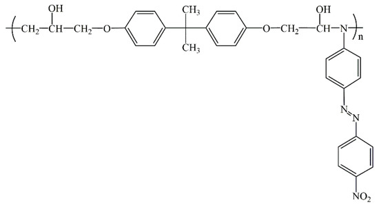
Figure 1.
Chemical structure of polydisperse orange 3 (PDO3).
2.3. The Fabrication of the (PDO3-PS)/PDMS Film/Substrate System
The PDO3 and PS solutions with different weight ratios were obtained by dissolving PDO3 and PS in THF, respectively. Then, the mixed solution was obtained by mixing the THF solutions of PDO3 (e.g., 4 wt.% and 6 wt.%) and PS (e.g., 2 wt.%, 4 wt.%, 6 wt.%, and 8 wt.%) with different concentrations. The elastic substrate PDMS was first treated in a plasma processor (PDC 32G system, Harrick Plasma, Ithaca, NY, USA) for 30 s. The (PDO3-PS)/PDMS bilayer film/substrate system was then prepared by spin-coating the (PDO3-PS) mixed solution in THF to the PDMS soft substrate. Typical (3% PDO3-1% PS) blended films were obtained by spin-coating deposition of the mixed THF solution containing 3 wt.% PDO3 and 1 wt.% PS.
2.4. Surface Wrinkling of the (PDO3-PS)/PDMS Bilayer Induced by Static Selected Exposure to Laser Light
The as-prepared (PDO3-PS)/PDMS bilayers were exposed to a 450 nm laser light with various light intensities (from 3.79 to 6.40 W·cm−2) and irradiation times (from 30 to 120 s) and then cooled to room temperature after the light source was switched off. The light intensity was modulated by the input voltage of the light source. The copper grid used as a photomask was conformally covered on the film surface. After selective exposure was performed for a designated time, the copper grid was removed carefully. The resulting samples were kept in the dark for the subsequent experiments.
2.5. Surface Wrinkling of the (PDO3-PS)/PDMS Bilayer Induced by Direct Laser Writing
The as-prepared (PDO3-PS)/PDMS samples were exposed to a 450 nm laser light with various light intensities (from 5.07 to 16.20 W·cm−2) and moving speeds. A motion controller (LTS300 Long Travel Stage, Thorlabs, Newton, NJ, USA) was used to control the movement of the laser beam with a certain speed (varied from 0.1 to 2 mm·s−1). The resulting samples were kept in the dark for the subsequent experiments.
2.6. Characterization
The wrinkle morphology was characterized by using an inverted Observer Al optical microscope (Zeiss, Jena, Germany). The temperature change during the light irradiation was probed by an infrared camera (Ti450, FLUKE, Everett, WA, USA). The thickness of composite film was characterized by a thermal field emission scanning electron microscope (JSM-7800F, JEOL, Tokyo, Japan). The wrinkle wavelength (λ) is defined as the distance between two adjacent peaks and λ is measured by taking the average of at least fifteen peak-to-peak distances of parallel segments.
3. Results and Discussion
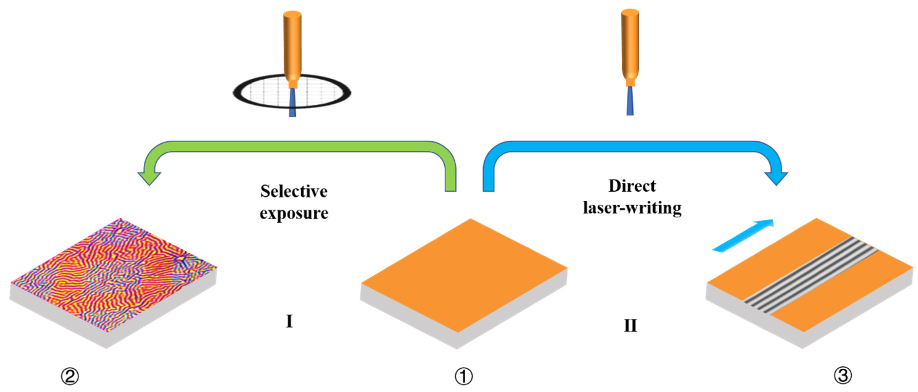
The schematic diagram of the different patterned surface wrinkle microstructures of the (PDO3-PS)/PDMS film/substrate system fabricated by two exposure modes is shown in Figure 2. One of the exposure modes is static selective exposure (Figure 2, route I). The copper grid used as a photomask is put on the surface of the (PDO3-PS)/PDMS sample (①), and then the sample is exposed to a 450 nm laser beam. Labyrinth wrinkles are formed on the surface of the exposed area, while oriented wrinkles perpendicular to the exposed area are formed on the unexposed area (②). The other exposure mode is dynamic moving exposure (Figure 2, route II), i.e., the surface of the (PDO3-PS)/PDMS film/substrate system is illuminated by a moving 450 nm laser beam. The exposed area forms the oriented wrinkles (③) parallel to the moving direction, while the unexposed area still maintains the original flat state.

Figure 2.
Schematic illustration of all-optical surface patterning strategy. Wrinkles with different morphology (②) and uniaxially oriented wrinkles (③) are induced by exposing the (PDO3-PS)/PDMS bilayer (①) to a high-intensity 450 nm laser light with a photomask (route I) or a high-intensity moving laser beam (route II).
3.1. Static Selective Exposure
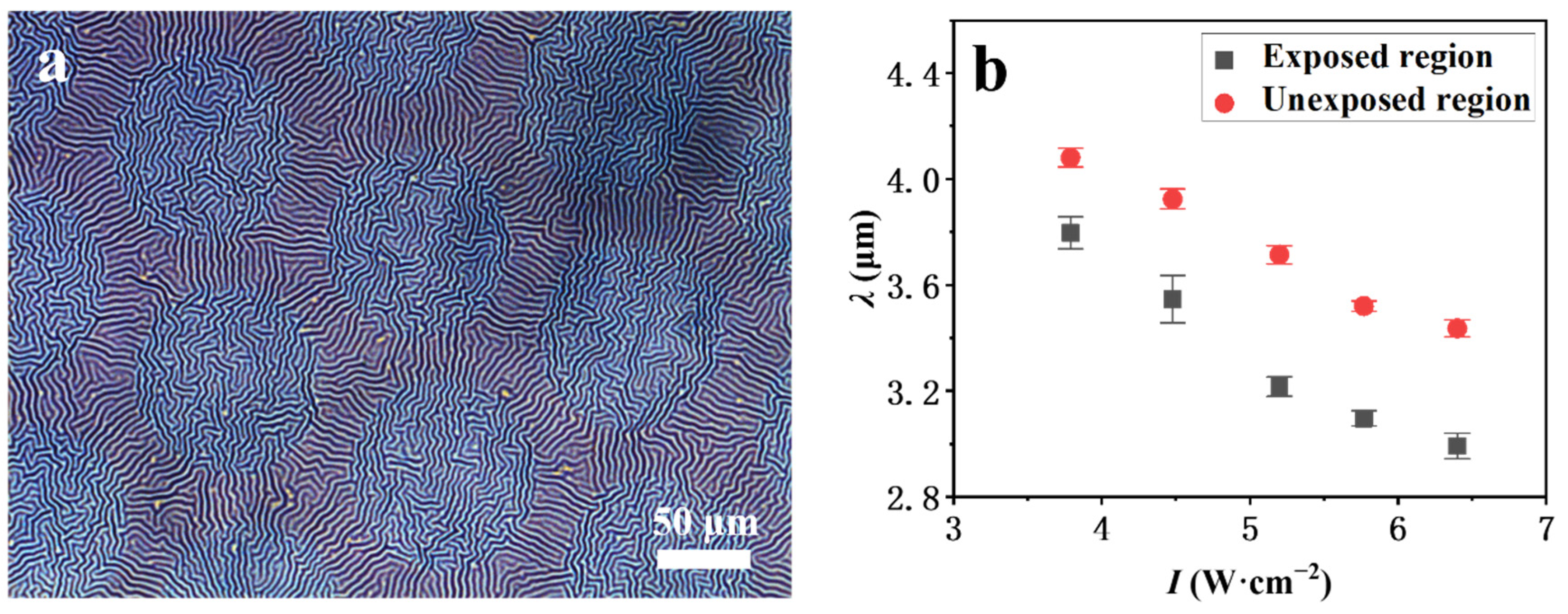
As shown in Figure 3a, wrinkles are formed on the surface of (PDO3-PS)/PDMS bilayer system after laser light irradiation. For the previously reported traditional bilayer system (e.g., PS/PDMS) [38,39], the surface wrinkling was basically induced by stimulations such as mechanical force and heating that required complex experimental steps. However, the wrinkles here are formed on the surface of the (PDO3-PS)/PDMS bilayer system simply through a single light irradiation step. Furthermore, in contrast to the wrinkles with a simple morphology and the single orientation state of a common wrinkling system, our selective-exposure-induced wrinkles are more hierarchical, i.e., labyrinth wrinkles are formed on the surface of the exposed region and oriented wrinkles are formed on the surface of the unexposed region. The in situ monitoring of the optical microscope showed that the whole surface of the film/substrate system remains smooth during illumination. After light illumination, the surface wrinkling occurs almost at the same time on the exposed area and unexposed area, and the wrinkling morphology becomes clearer as time goes on. The corresponding infrared thermal monitoring showed that the surface temperature of the film/substrate system increases gradually during the illumination. For example, when (3% PDO3-1% PS)/PDMS (hf = 59 nm) is irradiated by laser light with I = 3.79 W·cm−2 for 30 s, the surface temperature reaches about 102 °C (Figure S2). After the laser light exposure, the surface temperature decreases gradually. Obviously, the surface temperature change of the composite system originates from the 450 nm laser illumination. Because PS and PDMS have no photothermal conversion ability, the photothermal conversion effect comes from PDO3. Moreover, the surface wrinkling is related to the photothermal effect.

Figure 3.
(a) Optical images of wrinkles of (3%PDO3-1%PS)/PDMS (hf = 26 nm) induced by selective exposure (e.g., t = 30 s) through the copper grid (R200) on I = 6.40 W·cm−2. (b) The dependence of the wavelength (λ) of the wrinkles of exposed/unexposed region on the applied light intensity (I). Scale bars: 50 μm.
PDO3 is a typical pseudo-stilbene azobenzene polymer with an absorption band of 400–600 nm. A distinctive feature of PDO3 is that its n−π* absorption band is buried underneath the π−π* band and thus they are overlapped with the maximal peak at ∼470 nm (Figure S3). Namely, the 450 nm laser light can be absorbed simultaneously by the trans- and cis-isomers, which facilitates the trans/cis/trans isomerization cycle. In our case, during exposure to 450 nm laser light, the exposed (PDO3-PS)/PDMS is heated by the photothermal conversion effect of PDO3 [40,41], leading to a significantly increased surface temperature Th (Th is the elevated temperature due to the photothermal effect). Due to the mismatch of thermal expansion coefficients between the PDO3-PS film and the PDMS substrate, a compressive stress (σ) is generated during the cooling process after the irradiation, and σ can be expressed as
= Ef/(1 − ) is the plane strain modulus of the film, where Ef is the Young’s modulus of the film. is Poisson’s ratio, ε is the compressive strain, and αs and αf are the linear thermal expansion coefficients of the substrate and the film, respectively. ΔT = Th-T, where T is the cooling temperature that would decrease from Th to room temperature ~22 °C. When the σ caused by the photothermal effect exceeds the critical value (σc) (Equation (2)), in order to minimize the free energy of the system, spontaneous wrinkling of the surface occurs.
where εc is the critical wrinkling strain. According to the linear buckling theory [20,27,42], the critical wrinkling wavelength (λc) of the film/substrate system is shown in Equation (3):
where hf is the film thickness and is the plane strain modulus of the substrate. The adjustment of the wrinkle wavelength (λ) can be achieved by simply tuning the parameters such as the film thickness and modulus of PDO3-PS. This has been fully exploited in subsequent experiments.
Upon light irradiation, the temperature of the exposed area increases due to the photothermal conversion effect of PDO3. This further induces isotropic compressive stress in the film/substrate system during the subsequent cooling process, which results in the formation of random labyrinth wrinkles. Although the unexposed area is not irradiated by the laser light, the heat generated in the exposed area can be transferred to the adjacent unexposed area, leading to the formation of compressive stress in the unexposed area. Moreover, due to the existence of the photosoftening effect of PDO3 [1,43,44,45], the modulus of the exposed area is lower than that of the unexposed area, which induces an in situ soft/hard boundary on the surface. Therefore, the unexposed area is finally subjected to anisotropic compressive stress parallel to the soft/hard boundary, leading to the formation of corresponding oriented wrinkles perpendicular to the compressive stress, i.e., the final wrinkle orientation of the unexposed region is perpendicular to the exposed region (Figure 3a).
Furthermore, we investigated the influence of illumination conditions (light intensity (I) and exposing time (t)), the type of copper grids, and film thickness (hf) for selective exposure on the resulting surface morphology of the (PDO3-PS)/PDMS film/substrate system.
As expected from Equation (3), the wrinkle wavelength of the exposed area is smaller than that of the unexposed area because of the modulus decrease of the exposed area (Figure 3b). Naturally, the decrease in the modulus caused by the photosoftening effect of PDO3 will be greatly enhanced with the increase of the light intensity [43,44,46]. Therefore, the wrinkle wavelength of both the exposed area and unexposed area decreases with the increase of the illuminating light intensity (Figure 3b). Similarly, with the increase of exposing time, the degree of photosoftening of PDO3 will be greater, leading to the decrease of the wrinkle wavelength on the surface of the (3% PDO3-1% PS)/PDMS accordingly (Figure S4).
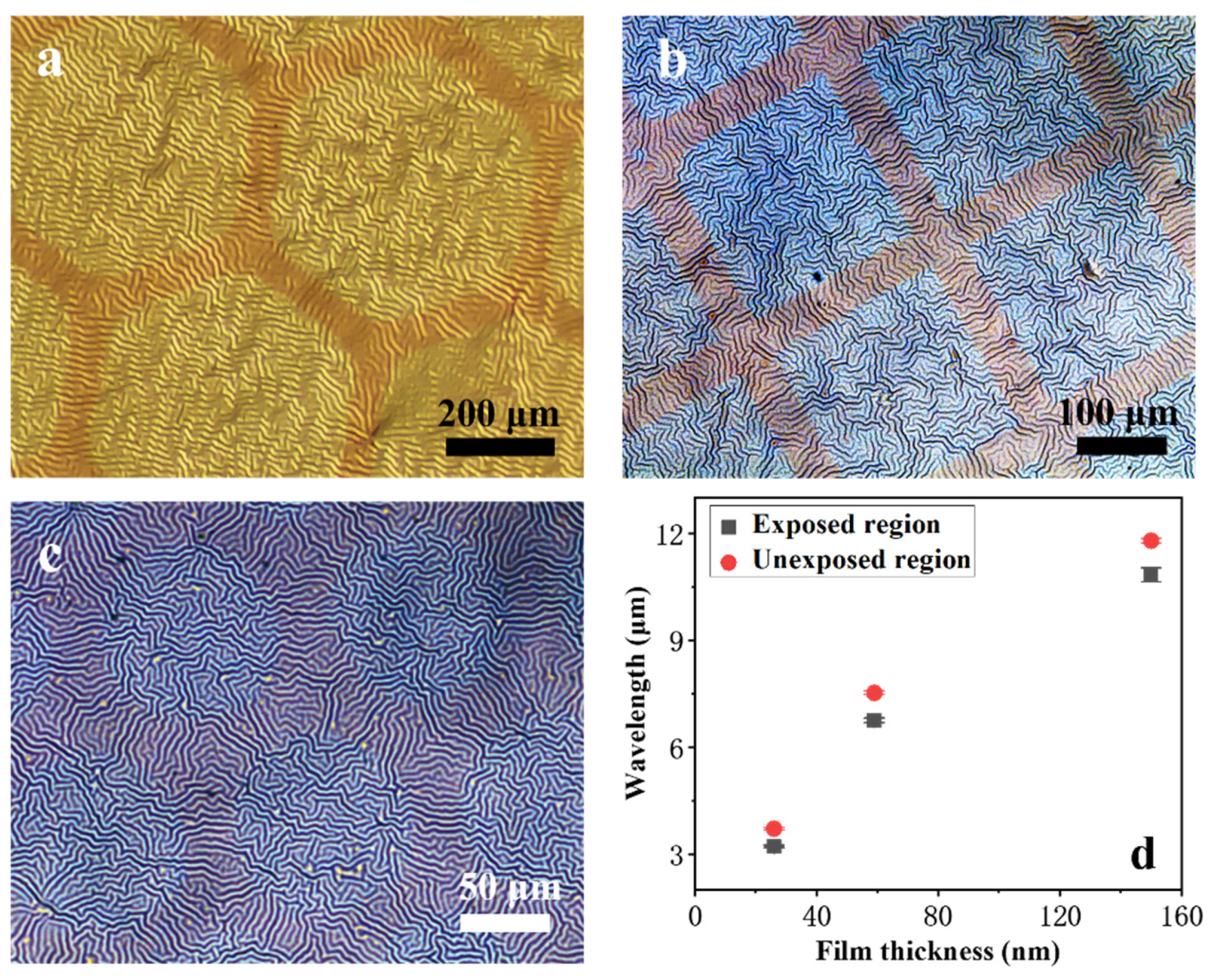
The influence of the type of copper grids on the surface wrinkle morphology of 3% PDO3-1% PS blend films induced by selective exposure is shown in Figure 4a–c. The results show that the geometric shape and size of the current exposed and unexposed area (i.e., the type of copper grids used for selective exposure (including the geometric shape of the copper grids holes and the mesh size of the copper grids)) have no significant influence on the wrinkle orientation. Namely, labyrinth wrinkles are formed on the exposed area and oriented wrinkles are formed on the unexposed area after selective exposure via different types of copper grids, which is further confirmed by Figure S5. Furthermore, we investigated the influence of film thickness on the wrinkle wavelength (Figure 4d). As expected from Equation (3), the surface wrinkle wavelength on the exposed/unexposed area increases with the increase of the film thickness when the type of copper grid and light intensity are fixed.

Figure 4.
Optical micrographs of wrinkles induced by exposing the (3% PDO3-1% PS)/PDMS bilayer with different hf to a high-intensity laser light (e.g., 5.2 W·cm−2/30 s) with different copper grids: (a) hf = 150 nm with H50 type of copper grid, (b) hf = 59 nm with S100 type of copper grid, and (c) hf = 26 nm with R200 type of copper grid. (d) The dependence of the wrinkle wavelength on the film thickness (e.g., 5.2 W·cm−2/30 s/H50).
3.2. Dynamic Moving Exposure
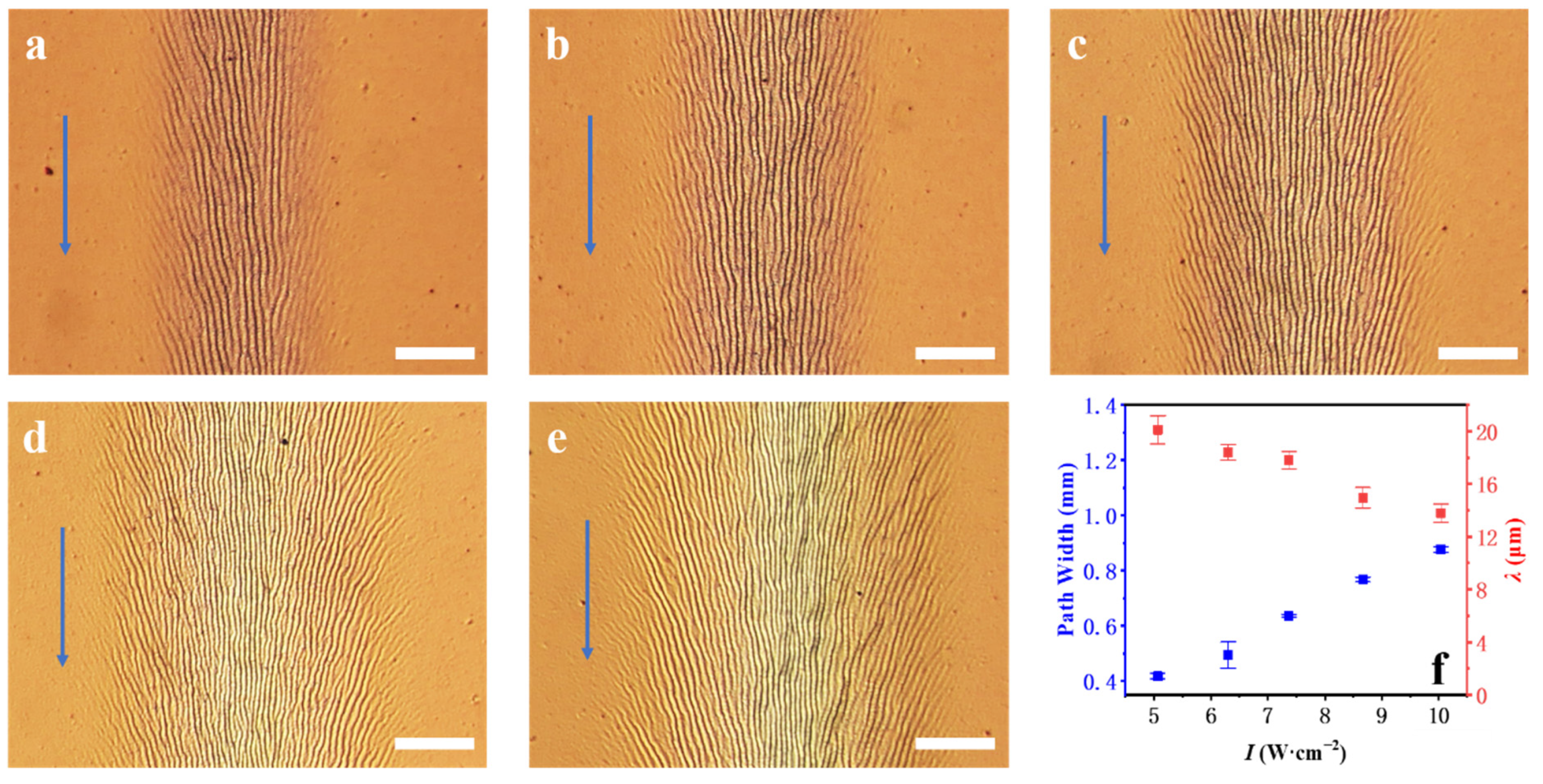
On the basis of the static selective exposure, we further explored the light-response behavior of the (PDO3-PS)/PDMS film/substrate system upon the moving exposure (Figure 1, route II). As shown in Figure 5a, after moving exposure, the central region of the exposed area on the film/substrate system forms the oriented wrinkles. The wrinkles of two sides regions near the unexposed area are bent outward relative to the parallel wrinkles. The unexposed area still maintains the initial flat state. Obviously, this is quite different from the random labyrinth wrinkles formed on the exposed area and the oriented wrinkles perpendicular to the exposed/unexposed boundary formed on the unexposed area after selective exposure. Furthermore, in contrast to the common boundary effect resulting in oriented wrinkling perpendicular to the bas-relief edges, our moving-exposure-induced aligned wrinkles are parallel to the exposed/unexposed boundary [20].

Figure 5.
Optical images of wrinkles of (2% PDO3-1% PS)/PDMS induced by a moving laser beam (e.g., V = 1 mm·s−1) on (a) I = 5.07 W·cm−2, (b) I = 6.30 W·cm−2, (c) I = 7.37 W·cm−2, (d) I = 8.67 W·cm−2, and (e) I = 10.04 W·cm−2. (f) The dependence of the wrinkling path width (D) and wavelength of the oriented wrinkles on the applied I. Scale bars: 200 μm.
As discussed above, due to the local photosoftening effect of azo polymer, the modulus of the exposed region decreases during laser light irradiation, while the modulus of the unexposed region has little change. As a result, a new soft/hard boundary is formed due to the modulus difference between the exposed/unexposed area. Upon moving the laser exposure, the exposed soft area is subjected to anisotropic compressive stress perpendicular to the soft/hard boundary [21,47], which causes the formation of the oriented wrinkles parallel to the soft/hard boundary on the surface of the exposed soft area. Moreover, due to the Gaussian distribution of the laser output, the light intensity in the center of the laser spot is higher than that in the edge spot. Thus, the degree of photo-softening of the edge region on the exposed area is relatively weak, which further induces the tendency of the wrinkles of the edge region to be vertically oriented to the boundary dominated by the geometric boundary effect. Meanwhile, due to the influence of the soft/hard boundary effect, the final orientation of the wrinkle on the edge region is between the parallel orientation and perpendicular orientation.
Furthermore, the influence of the laser light intensity (I) on wrinkling was investigated. When the laser beam was controlled to move in a straight line at the speed of 1 mm·s−1 and the light intensity increased from 5.07 to 10.04 W·cm−2 (Figure 5a–e), the wavelength of the parallel oriented wrinkles decreased with the increase of I, and the path width of the whole wrinkling region increased with the increase of I. The related data statistics are shown in Figure 5f. This correlation is attributed to the fact that the heat generated by the photo-thermal conversion effect of PDO3 increases with the increase of I (e.g., when I increases from 5.07 to 10.04 W·cm−2, the temperature increases from 176.2 to 221.5 °C) (Figure S6). Thus, the degree of photosoftening also increases with the increase of I, i.e., the modulus of the central area in the PDO3-PS film (Ef) decreases with the increase of I. According to Equation (3), it can be expected that the wavelength of the parallel oriented wrinkles of the central area will decrease with the increase of I. Moreover, due to the Gaussian distribution of the laser intensity, the temperature on the exposed area is higher in the center and lower in the two sides. When the light intensity is small, only the central region can meet the critical wrinkling condition (σ > σc). Subsequently, the increases of light intensity result in the increase of the temperature of the exposed area, gradually leading to the thermal-induced compressive stress increases. Therefore, the wider area meets the critical wrinkling condition, and then wrinkles are formed on the wider area. Similarly, the oriented wrinkle wavelength decreases with the decrease of the moving speed (V), and the wrinkling path width increases with the decrease of V (Figure S7).
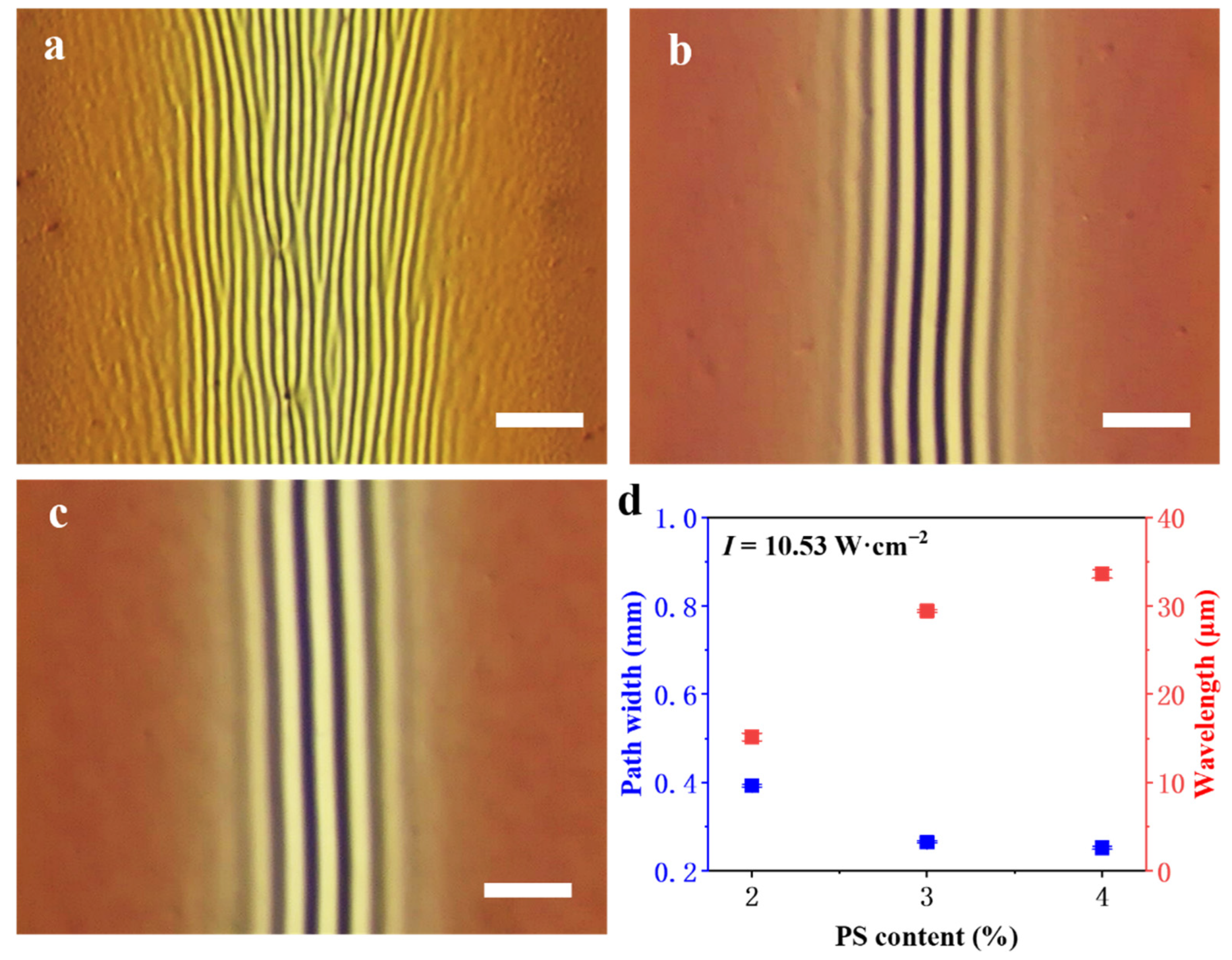
The influence of PS content on the wrinkling induced by moving laser irradiation is shown in Figure 6. Under the condition of I = 10.53 W·cm−2 and V = 1 mm·s−1, the wrinkle wavelength of the exposed area of the (PDO3-PS)/PDMS system increases with the increase of PS content, while the wrinkling path width decreases with the increase of PS content (Figure 6d). The variation is the same for the other light intensities applied (Figure S8). Since PS is a non-photosensitive polymer, light irradiation has nearly no influence on the modulus of PS. Therefore, the higher the content of PS, the smaller the decrease of the modulus of the PDO3-PS blended film caused by light irradiation. In addition, the SEM results of the cross section of the blend film show that the thicknesses of the three films with PS contents of 2%, 3%, and 4% were 235, 375, and 514 nm, respectively (Figure S9). Namely, with the increase of PS content, the modulus and thickness of the blended film both increase, so the corresponding wrinkle wavelength increases according to Equation (3). For the PDO3-PS films, the overall modulus increases with the increase of PS content, and the critical wrinkling stress (σc) increases according to Equation (2). Thus, the path width of the area which can meet the critical wrinkling condition decreases with the increase of PS content. Moreover, the orientation degree of the ordered wrinkles on the exposed area increases with the increase of PS content, which may be related to the boundary effect. It has been reported previously [48,49] that the increase of wrinkle wavelength λ and the decrease of wrinkling path width (D) lead to the increase of λ/D and the enhancement of the corresponding boundary effect, which finally leads to the more obvious wrinkle orientation (Figure 6a–c).

Figure 6.
Optical images of wrinkles of (a) (2% PDO3-2% PS)/PDMS, (b) (2% PDO3-3% PS)/PDMS, and (c) (2% PDO3-4% PS)/PDMS induced by a moving laser beam (e.g., I = 10.53 W·cm−2, V = 1 mm·s−1). (d) The dependence of the wrinkling path width and the wrinkle wavelength on the PS content. Scale bars: 100 μm.
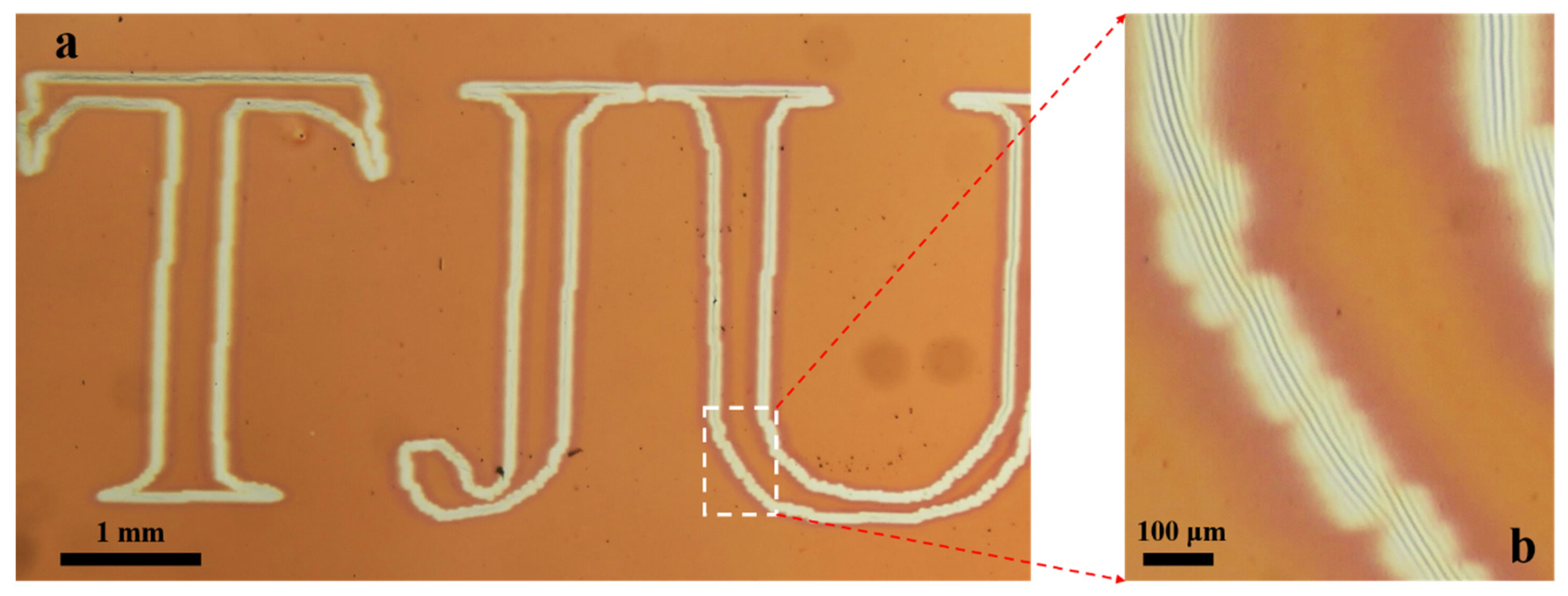
Here, we further wrote wrinkled micropatterns such as “TJU” on the surface of the film/substrate system by controlling the moving path of the laser beam, i.e., using laser direct writing technology (Figure 7a). The result of Figure 7b shows that the written wrinkle orientation remains highly parallel to the direction of laser writing even under the curved writing path.

Figure 7.
Optical image (a,b) of path-guided oriented wrinkles (TJU) of (2% PDO3-2% PS)/PDMS induced by a moving high-intensity laser beam (e.g., 16.20 W·cm−2/1.0 mm·s−1).
In general, in order to obtain highly oriented surface wrinkles of the bilayer system, a template is usually used to pattern the substrate or surface layer [50,51]. In contrast to their methods, our light-controlled moving exposure strategy is more flexible in that the ordered surface wrinkle morphology and pattern information of any prefabricated path can be easily obtained by using this simple laser direct writing technology.
4. Conclusions
In this paper, a non-photosensitive polymer PS is introduced to form a photosensitive blended film by mixing with an azo polymer PDO3, which results in controllable light-induced wrinkling on the surface of the blended film by exploiting the unique photoresponsivity of PDO3. Under the static selective exposure mode, random wrinkles are formed on the exposed area, and oriented wrinkles perpendicular to the boundary are formed on the unexposed area. Under the dynamic moving exposure mode, the exposed area forms aligned wrinkles that are highly parallel to the laser writing direction. The influence of the illumination conditions, film thickness, and composition of the blended film on the wrinkle morphology were systematically investigated. The all-optical surface wrinkling strategy based on the azo polymer blended film/substrate system reported in this paper is expected to be extended to other blended systems with functional components, which would realize the light-induced surface micro/nano patterning of functional composite film, and broaden its use in the fields of information writing and anti-counterfeiting.
Supplementary Materials
The following supporting information can be downloaded at: https://www.mdpi.com/article/10.3390/coatings12050608/s1, Figure S1: Detailed information of different types of copper grids: (a) 50 mesh-sized hexagonal holes (H50), (b) 100 mesh-sized hexagonal holes (H100), (c) 100 mesh-sized square holes (S100), (d) 200 mesh-sized round holes (R200), (e) 300 mesh-sized square holes (S300), (f) 400 mesh-sized round holes (R400), and (g) 500 mesh-sized round holes. (h) Detailed information on size parameters of holes (D1) and skeletons (D2) of different types of copper grids, Figure S2: The dependence of surface temperature (T) of the (3% PDO3-1% PS)/PDMS with different hf induced by selective exposure (t = 30 s) on the applied I, Figure S3: UV-vis absorption spectra of PDO3 film, Figure S4: Optical images of wrinkles of (3% PDO3-1% PS)/PDMS (hf = 59 nm) induced by selective exposure (e.g., I = 5.20 W·cm−2) via the copper grid (H100) under (a) t = 0 s, (b) t = 30 s, (c) t = 60 s, (d) t = 90 s, and (e) t = 120 s. (f) The dependence of the wavelength of the wrinkles of exposed/unexposed region on the applied t. Scale bars: 100 μm, Figure S5: Optical images of wrinkles of (3% PDO3-1% PS)/PDMS (hf = 26 nm) induced by selective exposure (e.g., I = 5.77 W·cm−2, t = 30 s) via different types of copper grids: (a) H100, (b) R200, (c) H200, (d) S300, (e) R400, and (f) R500. Scale bars: 50 μm, Figure S6: The dependence of surface temperature of the (2% PDO3-1% PS)/PDMS upon the 450 nm laser light exposure for 10 s on the applied I, Figure S7: Optical images of wrinkles of (2% PDO3-1% PS)/PDMS induced by a moving laser exposure (e.g., I = 8.67 W·cm−2) under (a) V = 2 mm·s−1, (b) V = 1.5 mm·s−1, (c) V = 0.5 mm·s−1, and (d) V = 0.1 mm·s−1. (e) The dependence of the wrinkling path width and wavelength of the oriented wrinkles on the applied V. Scale bars: 200 μm, Figure S8: The dependence of the wrinkling path width and the wrinkle wavelength of (2% PDO3-PS)/PDMS on the PS content. The wrinkles are induced by moving laser exposure (e.g., V = 1 mm·s−1) with different light intensities: (a) I = 8.67 W·cm−2, (b) I = 12.46 W·cm−2, and (c) I = 14.44 W·cm−2, Figure S9: SEM images of the cross-sectional part of the (a) 2% PDO3-2% PS, (b) 2% PDO3-3% PS, and (c) 2% PDO3-4% PS blend films.
Author Contributions
Conceptualization, C.L.; methodology, J.W.; software, J.W.; validation, B.W., J.W., X.H. and C.L.; formal analysis, J.W.; investigation, B.W.; resources, C.L.; data curation, B.W.; writing—original draft preparation, B.W.; writing—review and editing, J.W. and C.L.; visualization, B.W.; supervision, J.W.; project administration, C.L.; funding acquisition, J.W., X.H. and C.L. All authors have read and agreed to the published version of the manuscript.
Funding
This research was funded by National Natural Science Foundation of China (No. 21875160), the Natural Science Foundation of Tianjin (No. 20JCQNJC00870), and the Scientific Research Project of Tianjin Municipal Education Commission (No. 2020KJ054).
Institutional Review Board Statement
Not applicable.
Informed Consent Statement
Not applicable.
Data Availability Statement
Not applicable.
Conflicts of Interest
The authors declare no competing financial interest.
References
- Zong, C.; Zhao, Y.; Ji, H.; Han, X.; Xie, J.; Wang, J.; Cao, Y.; Jiang, S.; Lu, C. Tuning and erasing surface wrinkles by reversible visible-light-induced photoisomerization. Angew. Chem. Int. Ed. 2016, 55, 3931–3935. [Google Scholar] [CrossRef] [PubMed]
- Yang, X.; Zhao, Y.; Xie, J.; Han, X.; Wang, J.; Zong, C.; Ji, H.; Zhao, J.; Jiang, S.; Cao, Y.; et al. Bioinspired fabrication of free-standing conducting films with hierarchical surface wrinkling patterns. ACS Nano 2016, 10, 3801–3808. [Google Scholar] [CrossRef] [PubMed]
- Du, Q.; Guan, Y.; Zhu, X.X.; Zhang, Y. Swelling-induced surface instability patterns guided by pre-introduced structures. Soft Matter 2015, 11, 1937–1944. [Google Scholar] [CrossRef] [PubMed]
- Hou, H.; Yin, J.; Jiang, X. Smart patterned surface with dynamic wrinkles. Acc. Chem. Res. 2019, 52, 1025–1035. [Google Scholar] [CrossRef]
- Jung, W.-B.; Cho, K.M.; Lee, W.-K.; Odom, T.W.; Jung, H.-T. Universal method for creating hierarchical wrinkles on thin-film surfaces. ACS Appl. Mater. Interfaces 2018, 10, 1347–1355. [Google Scholar] [CrossRef]
- Lee, W.-K.; Odom, T.W. Designing hierarchical nanostructures from conformable and deformable thin materials. ACS Nano 2019, 13, 6170–6177. [Google Scholar] [CrossRef]
- Lee, W.-K.; Engel, C.J.; Huntington, M.D.; Hu, J.; Odom, T.W. Controlled three-dimensional hierarchical structuring by memory-based, sequential wrinkling. Nano Lett. 2015, 15, 5624–5629. [Google Scholar] [CrossRef]
- Yang, S.; Khare, K.; Lin, P.-C. Harnessing surface wrinkle patterns in soft matter. Adv. Funct. Mater. 2010, 20, 2550–2564. [Google Scholar] [CrossRef]
- Chan, E.P.; Smith, E.J.; Hayward, R.C.; Crosby, A.J. Surface wrinkles for smart adhesion. Adv. Mater. 2008, 20, 711–716. [Google Scholar] [CrossRef]
- Jeong, H.E.; Kwak, M.K.; Suh, K.Y. Stretchable, adhesion-tunable dry adhesive by surface wrinkling. Langmuir 2010, 26, 2223–2226. [Google Scholar] [CrossRef]
- Vajpayee, S.; Khare, K.; Yang, S.; Hui, C.-Y.; Jagota, A. Adhesion selectivity using rippled surfaces. Adv. Funct. Mater. 2011, 21, 547–555. [Google Scholar] [CrossRef]
- Davis, C.S.; Martina, D.; Creton, C.; Lindner, A.; Crosby, A.J. Enhanced adhesion of elastic materials to small-scale wrinkles. Langmuir 2012, 28, 14899–14908. [Google Scholar] [CrossRef] [PubMed]
- Khare, K.; Zhou, J.; Yang, S. Tunable open-channel microfluidics on soft poly(dimethylsiloxane) (PDMS) substrates with sinusoidal grooves. Langmuir 2009, 25, 12794–12799. [Google Scholar] [CrossRef]
- Zhang, H.; Zhu, H.; Liang, X.; Liu, P.; Zhang, Q.; Zhu, S. Wrinkled smart surfaces: Enhanced switchable wettability and directional liquid transportation. Appl. Surf. Sci. 2020, 513, 145810. [Google Scholar] [CrossRef]
- Chung, J.Y.; Youngblood, J.P.; Stafford, C.M. Anisotropic wetting on tunable micro-wrinkled surfaces. Soft Matter 2007, 3, 1163–1169. [Google Scholar] [CrossRef] [PubMed]
- Kim, J.B.; Kim, P.; Pégard, N.C.; Oh, S.J.; Kagan, C.R.; Fleischer, J.W.; Stone, H.A.; Loo, Y.-L. Wrinkles and deep folds as photonic structures in photovoltaics. Nat. Photon 2012, 6, 327–332. [Google Scholar] [CrossRef]
- Lee, S.G.; Lee, D.Y.; Lim, H.S.; Lee, D.H.; Lee, S.; Cho, K. Switchable transparency and wetting of elastomeric smart windows. Adv. Mater. 2010, 22, 5013–5017. [Google Scholar] [CrossRef] [PubMed]
- Ohzono, T.; Suzuki, K.; Yamaguchi, T.; Fukuda, N. Tunable optical diffuser based on deformable wrinkles. Adv. Opt. Mater. 2013, 1, 374–380. [Google Scholar] [CrossRef]
- Yu, S.; Li, L.; Wang, J.; Liu, E.; Zhao, J.; Xu, F.; Cao, Y.; Lu, C. Light-boosting highly sensitive pressure sensors based on bioinspired multiscale surface structures. Adv. Funct. Mater. 2020, 30, 1907091. [Google Scholar] [CrossRef]
- Bowden, N.B.; Brittain, S.T.; Evans, A.G.; Hutchinson, J.W.; Whitesides, G.M. Spontaneous formation of ordered structures in thin films of metals supported on an elastomeric polymer. Nature 1998, 393, 146–149. [Google Scholar] [CrossRef]
- Huck, W.T.S.; Bowden, N.; Onck, P.; Pardoen, T.; Hutchinson, A.J.W.; Whitesides, G.M. Ordering of spontaneously formed buckles on planar surfaces. Langmuir 2000, 16, 3497–3501. [Google Scholar] [CrossRef]
- Wang, J.; Zheng, Y.; Li, L.; Liu, E.; Zong, C.; Zhao, J.; Xie, J.; Xu, F.; König, T.A.F.; Saphiannikova, M.G.; et al. All-optical reversible azo-based wrinkling patterns with high aspect ratio and polarization-independent orientation for light-responsive soft photonics. ACS Appl. Mater. Interfaces 2019, 11, 25595–25604. [Google Scholar] [CrossRef]
- Li, F.; Hou, H.; Yin, J.; Jiang, X. Near-infrared light–responsive dynamic wrinkle patterns. Sci. Adv. 2018, 4, eaar5762. [Google Scholar] [CrossRef] [Green Version]
- Chen, C.-M.; Yang, S. Wrinkling instabilities in polymer films and their applications. Polym. Int. 2012, 61, 1041–1047. [Google Scholar] [CrossRef]
- Chen, D.; Yoon, J.; Chandra, D.; Crosby, A.J.; Hayward, R.C. Stimuli-responsive buckling mechanics of polymer films. J. Polym. Sci. Part B: Polym. Phys. 2014, 52, 1441–1461. [Google Scholar] [CrossRef] [Green Version]
- Chung, J.Y.; Nolte, A.J.; Stafford, C.M. Surface wrinkling: A versatile platform for measuring thin-film properties. Adv. Mater. 2011, 23, 349–368. [Google Scholar] [CrossRef] [PubMed]
- Jiang, H.; Khang, D.-Y.; Song, J.; Sun, Y.; Huang, Y.; Rogers, J.A. Finite deformation mechanics in buckled thin films on compliant supports. Proc. Natl. Acad. Sci. USA 2007, 104, 15607–15612. [Google Scholar] [CrossRef] [Green Version]
- Khang, D.-Y.; Rogers, J.A.; Lee, H.H. Mechanical buckling: Mechanics, metrology, and stretchable electronics. Adv. Funct. Mater. 2009, 19, 1526–1536. [Google Scholar] [CrossRef]
- Schweikart, A.; Fery, A. Controlled wrinkling as a novel method for the fabrication of patterned surfaces. Mikrochim. Acta 2009, 165, 249–263. [Google Scholar] [CrossRef]
- Zeng, S.; Li, R.; Freire, S.G.; Garbellotto, V.M.M.; Huang, E.Y.; Smith, A.T.; Hu, C.; Tait, W.R.T.; Bian, Z.; Zheng, G.; et al. Moisture-responsive wrinkling surfaces with tunable dynamics. Adv. Mater. 2017, 29, 1700828. [Google Scholar] [CrossRef]
- Stenberg, H.; Maaranen, J.; Suvanto, M.; Pakkanen, T.T. Solvent-assisted and thermal wrinklings of argon plasma treated polystyrene coatings on silicon substrate. Surf. Coat. Technol. 2014, 238, 133–138. [Google Scholar] [CrossRef]
- Rhee, D.; Lee, W.-K.; Odom, T.W. Crack-free, soft wrinkles enable switchable anisotropic wetting. Angew. Chem. Int. Ed. 2017, 56, 6523–6527. [Google Scholar] [CrossRef] [PubMed]
- Takeshima, T.; Liao, W.-Y.; Nagashima, Y.; Beppu, K.; Hara, M.; Nagano, S.; Seki, T. Photoresponsive surface wrinkle morphologies in liquid crystalline polymer films. Macromolecules 2015, 48, 6378–6384. [Google Scholar] [CrossRef]
- Wang, J.; Xie, J.; Zong, C.; Han, X.; Zhao, J.; Jiang, S.; Cao, Y.; Fery, A.; Lu, C. Light-modulated surface micropatterns with multifunctional surface properties on photodegradable polymer films. ACS Appl. Mater. Interfaces 2017, 9, 37402–37410. [Google Scholar] [CrossRef] [PubMed]
- Xie, M.; Xu, F.; Zhang, L.; Yin, J.; Jiang, X. Reversible surface dual-pattern with simultaneously dynamic wrinkled topography and fluorescence. ACS Macro Lett. 2018, 7, 540–545. [Google Scholar] [CrossRef]
- Yoon, J.; Bian, P.; Kim, J.; McCarthy, T.J.; Hayward, R.C. Local Switching of chemical patterns through light-triggered unfolding of creased hydrogel surfaces. Angew. Chem. Int. Ed. 2012, 51, 7146–7149. [Google Scholar] [CrossRef]
- Kim, M.J.; Yoo, S.J.; Kim, D.Y. A Supramolecular chiroptical switch using an amorphous azobenzene polymer. Adv. Funct. Mater. 2006, 16, 2089–2094. [Google Scholar] [CrossRef]
- Son, H.; Chau, A.; Davis, C.S. Polymer thin film adhesion utilizing the transition from surface wrinkling to delamination. Soft Matter 2019, 15, 6375–6382. [Google Scholar] [CrossRef]
- Hyun, D.C.; Jeong, U. Substrate thickness: An effective control parameter for polymer thin film buckling on PDMS substrates. J. Appl. Polym. Sci. 2009, 112, 2683–2690. [Google Scholar] [CrossRef]
- Lee, K.M.; White, T.J. Photochemical mechanism and photothermal considerations in the mechanical response of monodomain, azobenzene-functionalized liquid crystal polymer networks. Macromolecules 2012, 45, 7163–7170. [Google Scholar] [CrossRef]
- Chen, Y.; Yu, H.; Quan, M.; Zhang, L.; Yang, H.; Lu, Y. Photothermal effect of azopyridine compounds and their applications. RSC Adv. 2015, 5, 4675–4680. [Google Scholar] [CrossRef]
- Huang, Z.; Hong, W.; Suo, Z. Nonlinear analyses of wrinkles in a film bonded to a compliant substrate. J. Mech. Phys. Solids 2005, 53, 2101–2118. [Google Scholar] [CrossRef]
- Ji, H.; Zhao, Y.; Zong, C.; Xie, J.; Han, X.; Wang, J.; Zhao, J.; Jiang, S.; Cao, Y.; Lu, C. Simple and versatile strategy to prevent surface wrinkling by visible light irradiation. ACS Appl. Mater. Interfaces 2016, 8, 19127–19134. [Google Scholar] [CrossRef]
- Lee, S.; Kang, H.S.; Park, J.-K. Directional photofluidization lithography: Micro/nanostructural evolution by photofluidic motions of azobenzene materials. Adv. Mater. 2012, 24, 2069–2103. [Google Scholar] [CrossRef] [PubMed]
- Zong, C.; Zhao, Y.; Ji, H.; Xie, J.; Han, X.; Wang, J.; Cao, Y.; Lu, C.; Li, H.; Jiang, S. Patterning surfaces on azo-based multilayer films via surface wrinkling combined with visible light irradiation. Macromol. Rapid Commun. 2016, 37, 1288–1294. [Google Scholar] [CrossRef] [PubMed]
- Karageorgiev, P.; Neher, D.; Schulz, B.; Stiller, B.; Pietsch, U.; Giersig, M.; Brehmer, L. From anisotropic photo-fluidity towards nanomanipulation in the optical near-field. Nat. Mater. 2005, 4, 699–703. [Google Scholar] [CrossRef] [PubMed]
- Guo, C.F.; Nayyar, V.; Zhang, Z.; Chen, Y.; Miao, J.; Huang, R.; Liu, Q. Path-guided wrinkling of nanoscale metal films. Adv. Mater. 2012, 24, 3010–3014. [Google Scholar] [CrossRef] [Green Version]
- Ding, W.; Yang, Y.; Zhao, Y.; Jiang, S.; Cao, Y.; Lu, C. Well-defined orthogonal surface wrinkles directed by the wrinkled boundary. Soft Matter 2013, 9, 3720–3726. [Google Scholar] [CrossRef]
- Yang, Y.; Han, X.; Ding, W.; Jiang, S.; Cao, Y.; Lu, C. Controlled free edge effects in surface wrinkling via combination of external straining and selective O2 plasma exposure. Langmuir 2013, 29, 7170–7177. [Google Scholar] [CrossRef] [PubMed]
- Lee, J.-H.; Ro, H.W.; Huang, R.; Lemaillet, P.; Germer, T.A.; Soles, C.L.; Stafford, C.M. Anisotropic, hierarchical surface patterns via surface wrinkling of nanopatterned polymer films. Nano Lett. 2012, 12, 5995–5999. [Google Scholar] [CrossRef]
- Yin, J.; Lu, C. Hierarchical surface wrinkles directed by wrinkled templates. Soft Matter 2012, 8, 6528–6534. [Google Scholar] [CrossRef]

Publisher’s Note: MDPI stays neutral with regard to jurisdictional claims in published maps and institutional affiliations. |
© 2022 by the authors. Licensee MDPI, Basel, Switzerland. This article is an open access article distributed under the terms and conditions of the Creative Commons Attribution (CC BY) license (https://creativecommons.org/licenses/by/4.0/).