Article

Development of Liquid Phase Sintering Silicon Carbide Composites for Light Water Reactor

1
Open Innovation Institute, Kyoto University, Gokasho, Uji 611-0011, Japan
2
Toshiba Energy Systems & Solutions Co., Shinsugita, Isogo-ku, Yokohama 235-8523, Japan
3
Institute for Materials Research, Tohoku University, 2-1-1 Katahira, Aoba-ku, Sendai 980-8577, Japan
4
Division of Mechanical Engineering, Dong-Eui Institute of Technology, 54, Yanji-ro, Busanjin, Busan 47230, Korea
5
Graduate School of Energy Science, Kyoto University, Gokasho, Uji 611-0011, Japan
*
Author to whom correspondence should be addressed.
Coatings 2022, 12(5), 623; https://doi.org/10.3390/coatings12050623
Submission received: 31 March 2022 / Revised: 22 April 2022 / Accepted: 29 April 2022 / Published: 3 May 2022
(This article belongs to the Special Issue Advanced Composites and Coatings for Nuclear Applications)

Abstract

:
Silicon carbide composites are expected for light water reactors. The objective is to understand the steam oxidation behavior and the high-temperature water corrosion behavior of the liquid phase sintering silicon carbide and to develop the liquid phase sintering silicon carbide composites, which are stable at the high-temperature water conditions in normal operation and the high-temperature steam conditions in a severe accident. The steam oxidation experiments were carried out at 1200 and 1400 °C. The high-temperature water corrosion experiments were carried out at 320 and 360 °C. The formation of the silicate, which is expected to have excellent resistance to the steam, was confirmed following the steam exposure at 1400 °C. High-temperature water corrosion resistance was improved by the formation of Yttrium Aluminum Garnet at the grain boundary. The particle-dispersion silicon carbide composite tubes with the modified condition were developed, and the thermal shock experiments from 1200 °C to ambient temperature were carried out. The composite tubes showed excellent oxidation and thermal shock resistance. The particle-dispersion liquid phase sintering silicon carbide composites with the modified condition are promising materials for light water reactors.

1. Introduction

Silicon carbide (SiC) composites are promising materials for nuclear fission, including very high-temperature reactor, gas-cooled fast reactor [1], and fusion reactor [2,3] systems due to engineered toughness by fiber reinforcement and intrinsic features of SiC, including low activation, chemical and environmental inertness, exceptional irradiation stability, and very high-temperature mechanical performance. The SiC composites have been applied to aircraft engines by GE Aviation [4]. The aerospace application is expected to expand [5]. The superior stability of SiC under high-temperature steam to that of metal is a critical motivation for light water reactor applications [6]. The SiC cladding material has the ability to prevent severe accidents where the current zirconium alloy melts [7]. The SiC material can also significantly reduce hydrogen production attributed to the reaction with the steam [8]. High-purity silicon carbide composites consisting of high purity and highly crystalline fibers and matrices have demonstrated excellent mechanical performance following neutron irradiation [9,10,11] and are now recognized as “nuclear grade” composites.
Highly crystalline matrices can be formed by chemical vapor infiltration (CVI) and liquid phase sintering (LPS). Steam oxidation behavior and high-temperature water corrosion behavior of SiC have been previously reported, in particular, for the chemical vapor deposition (CVD) SiC. Fundamental steam oxidation behavior has been reported, including SiO2 formation, bubble formation within the SiO2 scale, and the reaction of SiO2 with steam [12,13]. It has been reported that the high-temperature corrosion behavior was affected by the amount of dissolved oxygen and pH and grain boundary dissolved preferentially [14,15]. Sintering additives remain in the LPS SiC at the grain boundary and triple junction. The effect of the sintering additives on steam oxidation behavior and high-temperature corrosion behavior of the LPS SiC is not clear. The objective of this work is to understand the effect of the sintering additives in the LPS SiC on steam oxidation and high-temperature water corrosion behavior and to develop the LPS SiC composites for light water reactor application. The high-temperature steam environment is of interest for the other nuclear fission and fusion applications in severe accidents and for aerospace applications. The results in this paper can contribute to the applications.

2. Materials and Methods

2.1. Materials

The LPS SiC was prepared by sintering SiC powder (Nanomakers, Rambouillet, France) with average diameters of 35 nm with Al2O3 and Y2O3 sintering additives (Kojundo Chemical Laboratory Co., Ltd., Sakado, Japan) at 1850 °C with 20 MPa. The high purity CVD SiC (Dow Chemical Company, Midland County, MI, USA), the zirconium alloy (Zircaloy-2), and the Al5Y3O12 (Yttrium Aluminum Garnet: YAG, fabricated at Kyoto Univ.) were also prepared at 1850 °C with 20 MPa. The BN particle-dispersion SiC composite tubes were fabricated by the LPS. The matrices include BN powder (Maruka Corporation, Ltd., Ena, Japan) and sintered with Al2O3 and Y2O3 sintering additives (Kojundo Chemical Laboratory Co., Ltd., Sakado, Japan).

2.2. Methods

The LPS SiC and the CVD SiC were exposed in a 100% steam flow environment for 72 h at 1200 or 1400 °C. The specimen geometry was 10 × 10 × 2 mm. One specimen was used for each material and for each condition. The microstructure was observed by FE-SEM and analyzed by EDS following the experiments. The weight was measured for each specimen before and after the experiments. The thickness of the oxidation scale was measured from the SEM images. The weight changes were estimated from the thickness of the oxidation scales and compared with the measured weight changes normalized by the surface area. A phase diagram was obtained from CaTCalc SE, Research Institute of Computational Thermodynamics, Inc., Japan, to understand the reaction at high temperatures.
The high-temperature water corrosion experiments were carried out for the LPS SiC and the CVD SiC for 168 h at 320 and 360 °C. The specimen geometry was 40 × 10 × 3 mm or 30 × 10 × 2 mm. One specimen was used for each material and for each condition. The dissolved oxygen and the pressure was 8 or 2 ppm and 20 MPa, respectively. The microstructure was observed by FE-SEM and analyzed by EDS, XRD, and XPS. The weight was measured for each specimen before and after the experiments. The weight change was normalized by the surface area.
The thermal shock experiment was carried out using the LPS SiC composite tubes (10 mm inner diameter, 12 mm inner diameter, 35 or 55 mm long) and the monolithic SiC ceramic tubes (10 mm inner diameter, 12 mm inner diameter, 30 mm long). The tubes were heated and kept at 1200 °C in the air for 30 min and dropped into the water at ambient temperature. Four composite tubes and eight monolithic tubes were used. The thermal shock behaviors were recorded by the high flame rate camera.

3. Results and Discussion

3.1. Steam Oxidation

Figure 1 shows the LPS SiC, the CVD SiC, and the Zircaloy-2 following steam oxidation for 72 h at 1200 and 1400 °C. The Square plates were used for both the LPS SiC and the CVD SiC, and the tubes were used for Zircaloy-2. A rough surface was observed for the LPS SiC plate exposed at 1400 °C. Significant changes were not observed in the other SiC plates. The Zircaloy-2 tubes were deformed following exposure at 1200 °C and fractured following exposure at 1400 °C without any applied stress.
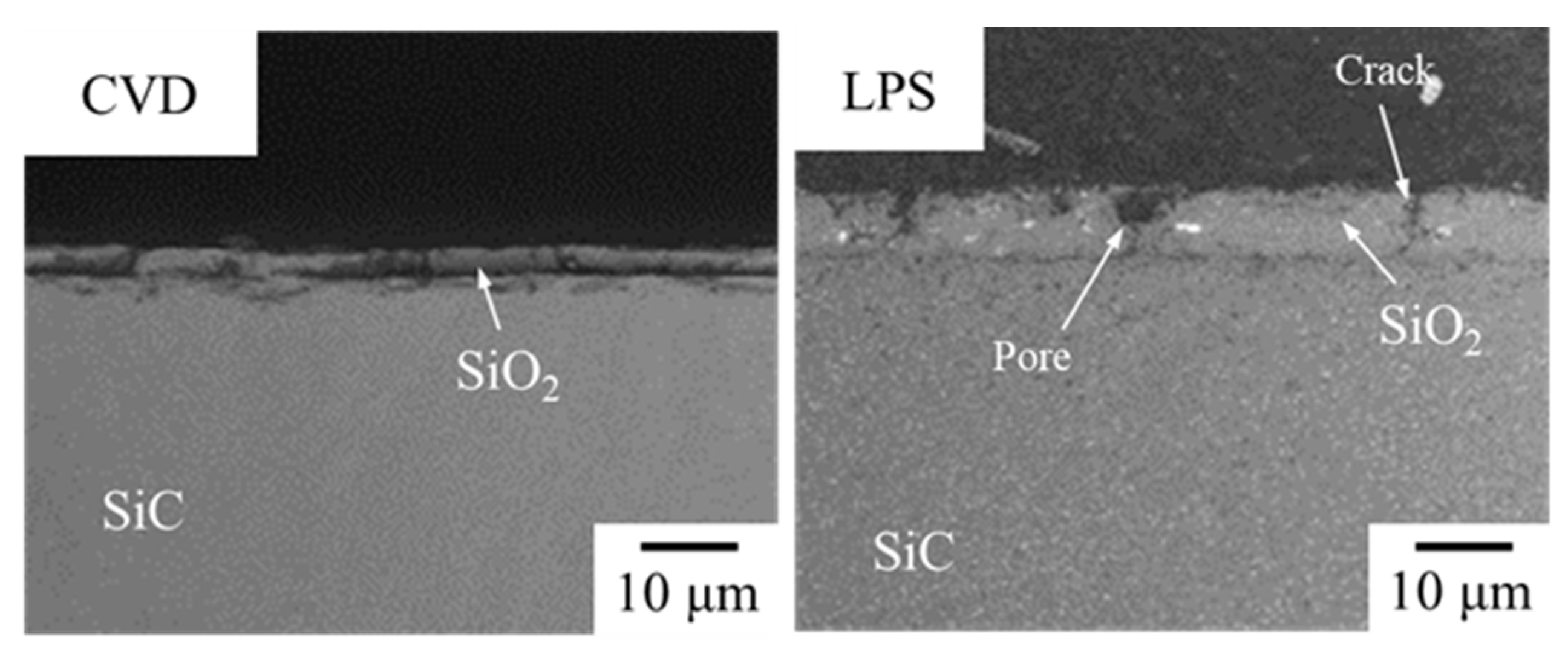
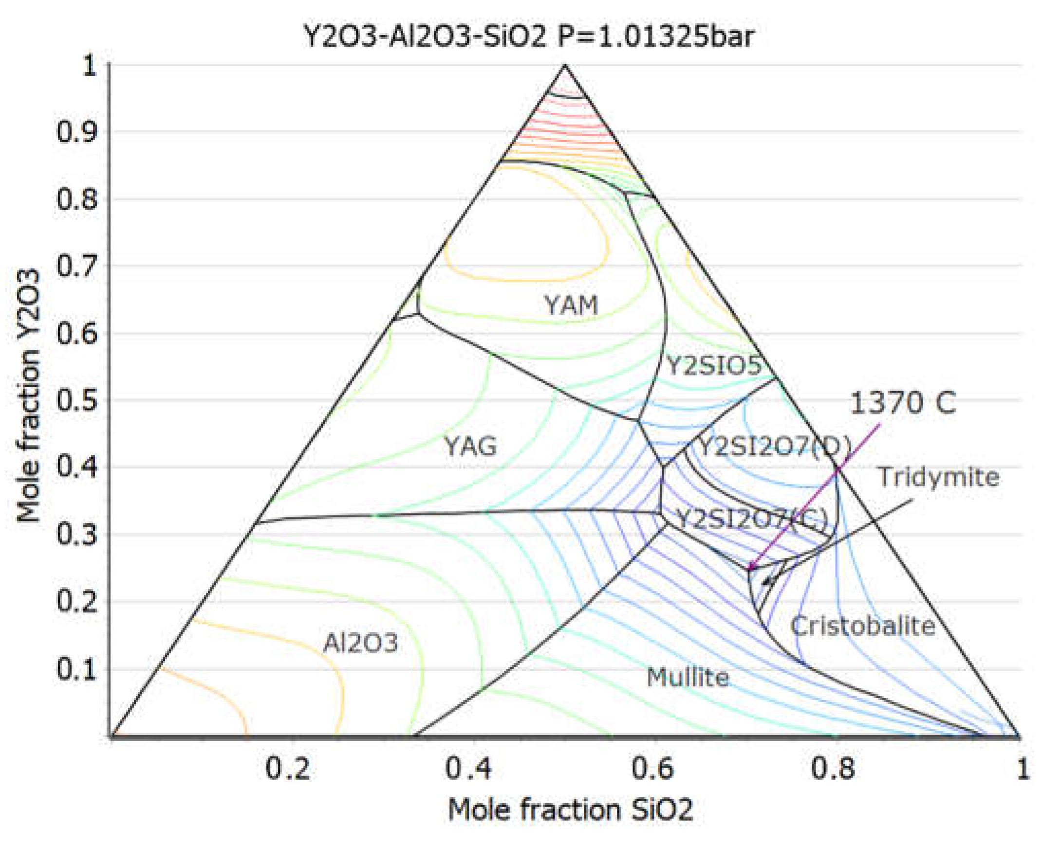
A relatively thin SiO2 scale was observed for the CVD SiC following exposure at 1200 °C, as shown in Figure 2. The LPS SiC showed a thicker SiO2 scale than that of the CVD SiC. The thickness of the SiO2 scale of the CVD SiC and the LPS SiC were approximately 4.0 ± 1.0 and 4.9 ± 2.0 µm, respectively. A significant change was observed for the LPS SiC following exposure at 1400 °C, as shown in Figure 3, while the oxidation behavior of the CVD was similar to that at 1200 °C. The thickness of the SiO2 scale of the CVD SiC and the LPS SiC were approximately 4.0 ± 1.0 and 22.8 ± 20.0 µm, respectively. A very rough SiO2 scale was formed in the LPS SiC. The large clusters of Y2Si2O7 were observed within the layers, including SiO2 and Al2SiO5, according to EDS analysis. The LPS SiC contained Al2O3 and Y2O3. SiO2 was formed by the oxidation of SiC. The eutectic point of Y2O3-Al2O3-SiO2 was calculated at 1370 °C from the phase diagram, as shown in Figure 4. It is considered that the eutectic reaction enhanced the formation of the complicated phase on the LPS SiC following exposure at 1400 °C.
The weight changes estimated from the thickness of the oxidation scales in the SEM images were compared with measured weight changes normalized by surface area in Figure 5. The weight gain was attributed to SiO2 formation. The weight loss was attributed to the reaction of SiO2 with the steam. Al2O3 was also considered to react with steam in the LPS SiC. The estimated values from the SEM images just include weight gain. The measured weight changes include both weight gain and loss. The followings are the reactions.
  • SiC + 3H2O(g) → SiO2 + 3H2(g) + CO(g) (Weight gain)
  • SiO2 + 2H2O(g) → Si(OH)4(g) (Weight loss)
  • Al2O3(s) + 3H2O(g) → 2Al(OH)3(g) (Weight loss)
The LPS SiC showed weight gain, while the CVD SiC showed weight loss. However, the thickness of the CVD SiC increased by approximately 5 ± 10 µm for each surface following exposure at 1200 °C and decreased by approximately 10 ± 10 µm following exposure at 1400 °C. The thickness of the LPS SiC decreased by approximately 10 ± 10 µm for each surface following exposure at 1200 °C and decreased by approximately 20 ± 20 µm following exposure at 1400 °C. The larger weight gain of the LPS SiC than that of the CVD SiC was attributed to the relatively thick oxidation scale. The amount of erosion of the LPS SiC by steam was larger than that of the CVD SiC in both temperatures.
The SiC materials have excellent high-temperature oxidation resistance compared to the Zircaloy materials. However, high-temperature steam environments in a severe accident are very severe even for the SiC material due to the reaction of SiO2 and steam. Large clusters of Y2Si2O7 were formed in the LPS SiC with Y2O3 and Al2O3 sintering additives following exposure at 1400 °C, which is above the eutectic point of Y2O3-Al2O3-SiO2. The rare earth (RE) silicate coatings have been candidates for the steam environment for aerospace applications [16]. The dense silicate coating was not formed in the Y2O3-Al2O3-SiO2 system. The SiC can be sintered with the other RE oxides, including Yb2O3 and Lu2O3. The RE silicate can be formed above the eutectic point of the RE oxide-Al2O3-SiO2 significantly. If the dense RE silicate is formed during the severe environmental condition, the LPS SiC composites can have significant grace time in a severe accident.

3.2. High-Temperature Water Corrosion

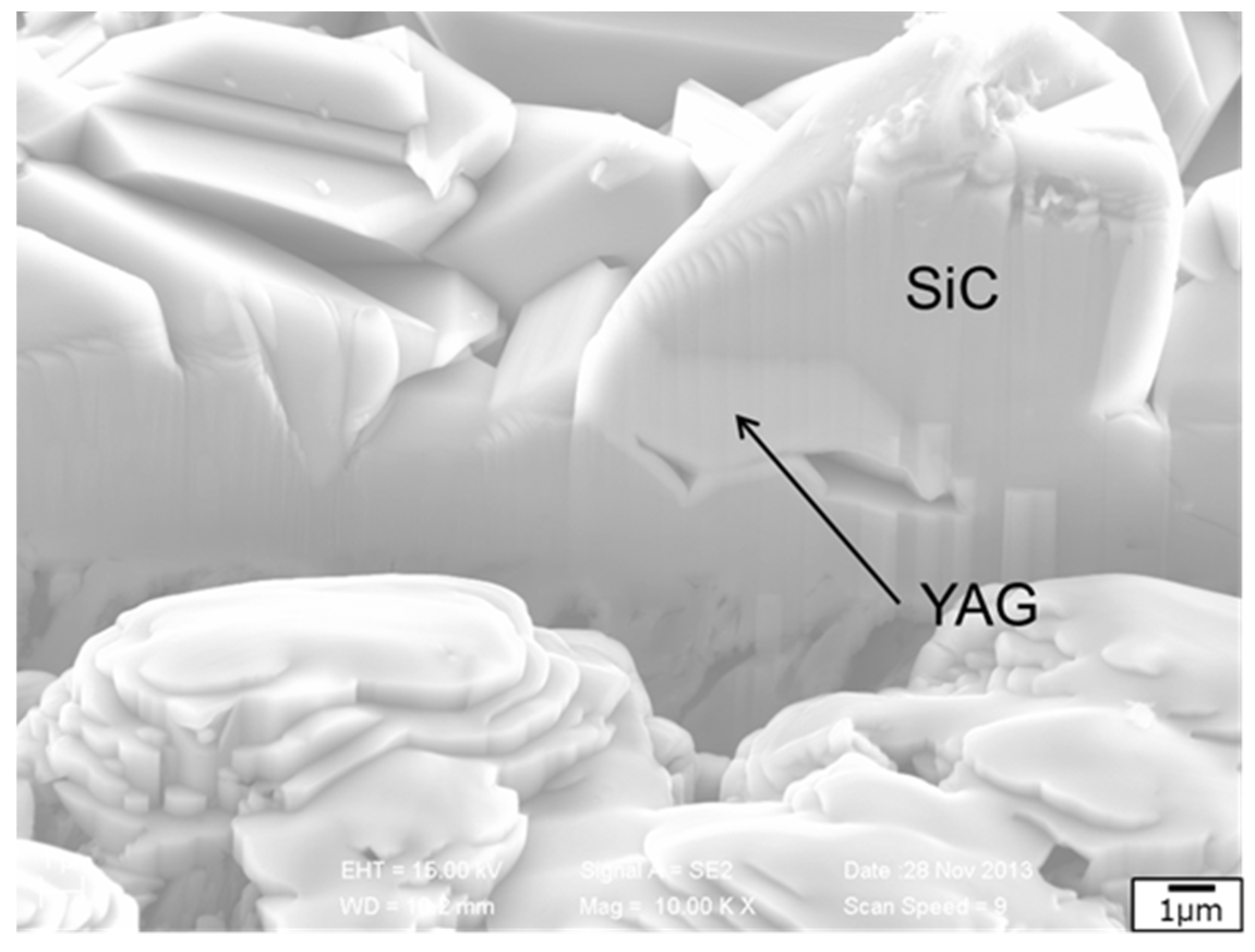
Significant corrosion was observed in the LPS SiC following the high-temperature water experiment with 8 ppm dissolved oxygen and 20 MPa pressure at 360 °C for 168 h, as shown in Figure 6. Figure 6 shows the surface of the LPS SiC following the corrosion experiment. The LPS SiC contained Al2O3 and Y2O3 sintering additives at the grain boundary. Most of the sintering additives dissolved in water. However, some sintering additives remained. The remaining sintering additives were identified as YAG crystals by XRD analysis. It is considered that the YAG formed from Al2O3 and Y2O3 sintering additives are stable in high-temperature water.
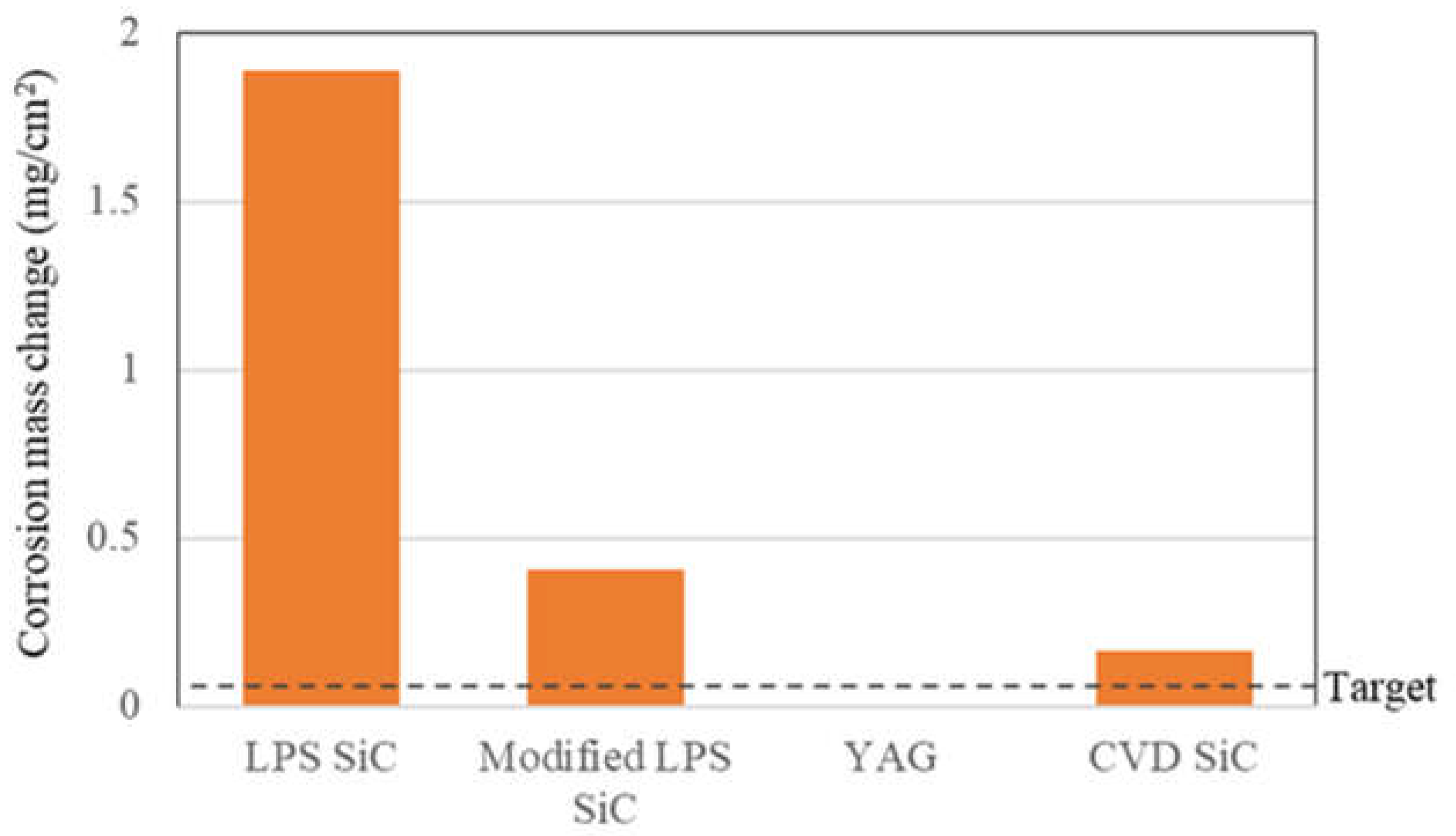
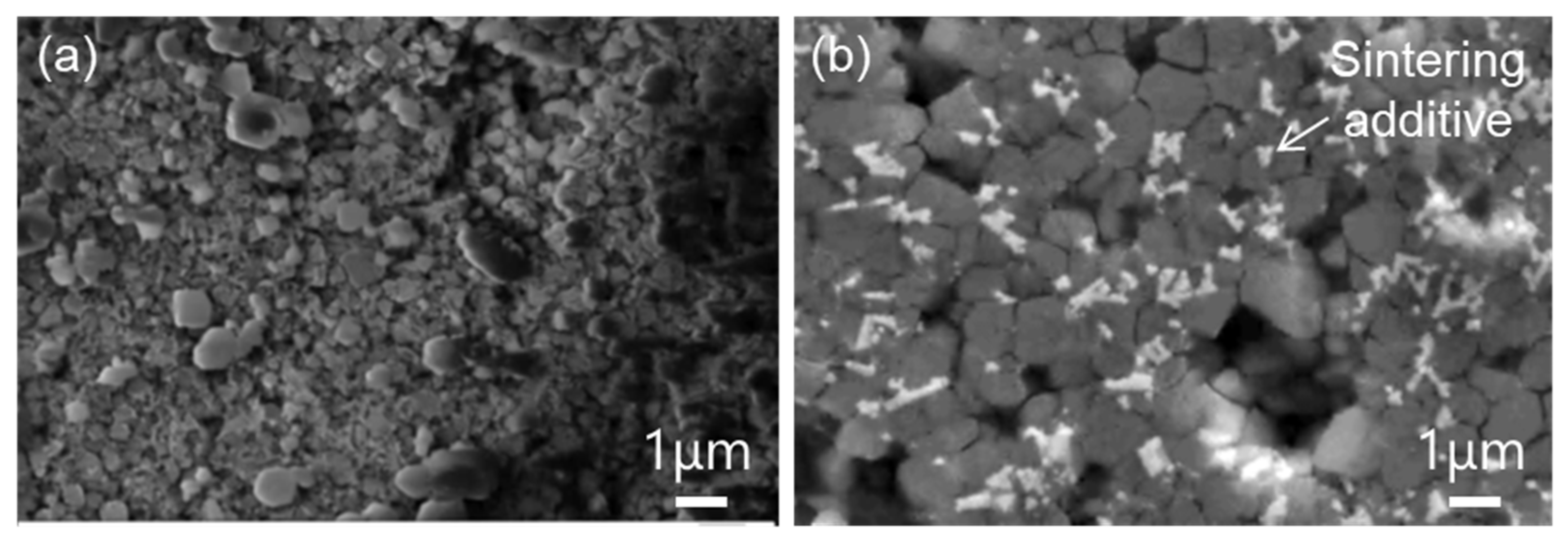
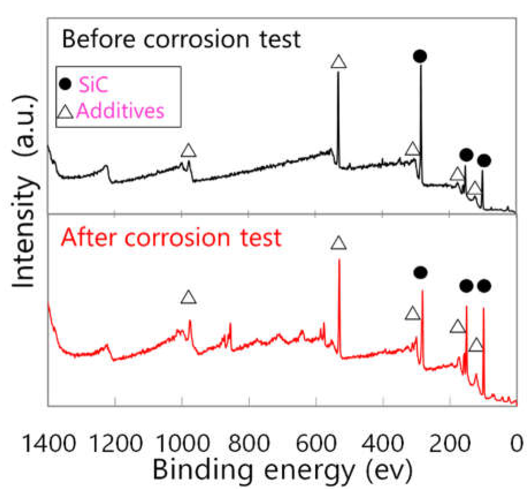
The LPS SiC was modified to form YAG at the grain boundary. The composition of Al2O3 and Y2O3 was changed to the YAG ratio. The amounts of corrosion of the LPS SiC, the modified LPS SiC, the YAG, and the CVD SiC following the high-temperature water corrosion experiment with 2 ppm dissolved oxygen and 20 MPa pressure at 320 °C for 168 h are compared in Figure 7. The mass change of each specimen before and after the corrosion test was divided by the surface area of each specimen. The YAG showed almost no corrosion and much better corrosion resistance than the CVD SiC. The corrosion behavior of the LPS SiC was significantly improved by YAG formation at the grain boundary and triple junction. Figure 8 shows FE-SEM images of the LPS SiC (a) and the modified LPS (b) surfaces following the corrosion experiment. The retained sintering additives with bright contrast were confirmed in the modified LPS SiC with YAG ratio sintering additives, while most of the sintering additives disappeared in the original LPS SiC. The remaining sintering additives were also confirmed by XPS analysis, as shown in Figure 9.
The grain boundary is the weakest link in terms of high-temperature water corrosion for both the CVD SiC [14,15] and the LPS SiC. The sintering additives retained at the grain boundary, and most of the sintering additives were unstable in high-temperature water. YAG showed excellent resistance and much lower corrosion than the CVD SiC. The LPS SiC was modified to form YAG at the grain boundary. The corrosion resistance improved significantly but was not better than CVD SiC. It was still difficult to form the YAG at the grain boundary completely. Some Y2O3 and Al2O3 remained at this moment. If the YAG is completely formed at the grain boundary, the LPS SiC is expected to have excellent high-temperature water corrosion resistance.

3.3. Liquid Phase Sintering SiC Composites for Light Water Reactor

The LPS SiC is not a perfect material in terms of steam oxidation. However, the oxidation resistance is superior to the Zircaloy material. The weakest link of conventional SiC composites in terms of oxidation is the fiber/matrix interphase. Typically, carbon (C) is considered the interphase for nuclear applications, and boron nitride (BN) is considered for aerospace applications. C is oxidized easily, forming CO or CO2 gas, and BN is also oxidized. If the interphase is oxidized, the SiC fiber is also oxidized. The degradation of the SiC fiber induces the degradation of mechanical properties of the composites [17]. The particle-dispersion SiC composites were developed without the fiber/matrix interphase [11,18]. The matrix contains particles such as C or BN instead of the interphase. Oxidation through the interphase can be prevented.
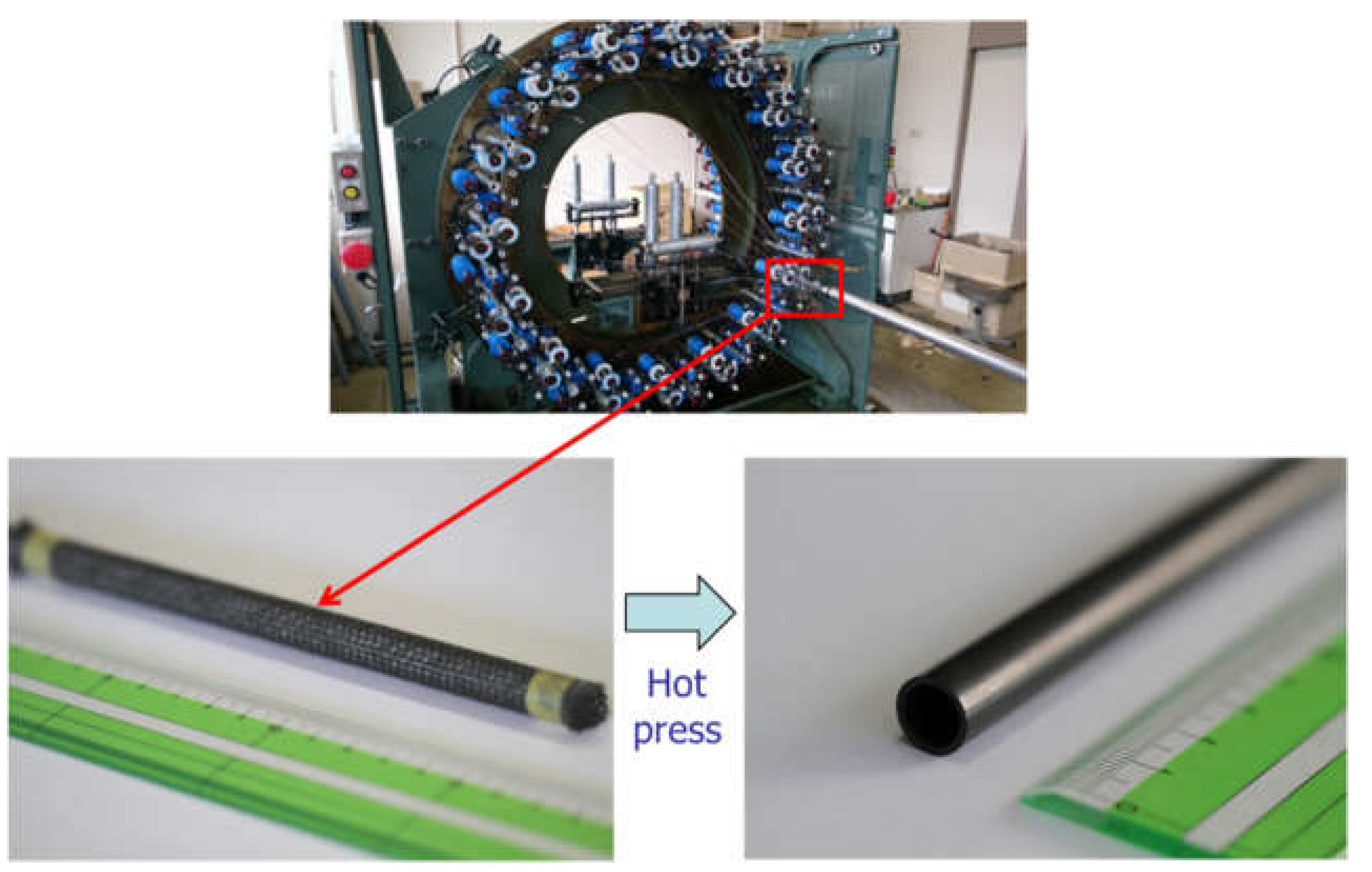
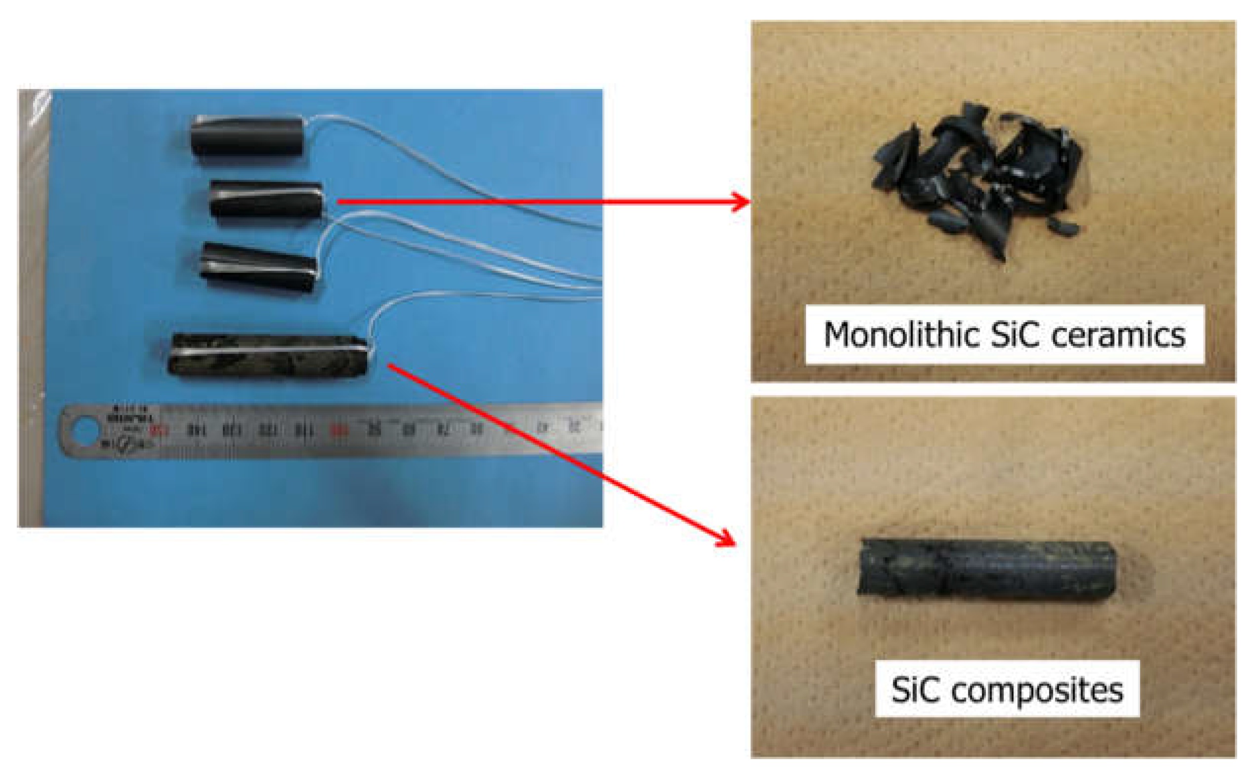
The BN particle-dispersion SiC composite tubes were fabricated utilizing a braiding technique, as shown in Figure 10. Hi-NicalonTM type-S fibers without coating were used for the braiding. The BN particle-dispersed SiC matrix was formed by the LPS method. Natural boron was used for the BN particle in this work. Boron-10 absorbs thermal neutrons significantly. Just boron-11 should be used for the light water cladding application. Al2O3 and Y2O3 were used with the YAG ratio. The thermal shock tests of the composites were carried out twice using the same tube. The composite tubes did not have any oxidation-resistant coating, such as CVD SiC coating. The composites did not break, while the monolithic SiC ceramic tubes without SiC fibers fractured into many small pieces just after being dropped into water in the first test, as shown in Figure 11.
The LPS SiC composite tubes were fabricated by the modified LPS condition and the excellent oxidation and thermal shock resistance. The materials were kept at 1200 °C in the air for the test. The thermal shock was applied to the oxidized materials. The high-temperature oxidation resistance is a significant feature of the particle-dispersion SiC composites without a fiber/matrix interphase. The optimal interphase thickness is in the order of 100 nm for the conventional SiC composites [19,20]. The CVD technique is used normally by coating SiC fibers. It is very difficult to have a uniform coating on the long cladding shape of the fiber preform. If the coating is applied in advance and the coated fibers are used in the preform by braiding, the coating is easily broken. The SiC composites without a fiber/matrix interphase have a significant advantage for complicated shaping.

4. Conclusions

Significant changes were not observed for the CVD SiC following steam oxidation at 1200 and 1400 °C and for the LPS SiC following steam oxidation at 1200 °C forming the thin SiO2 scale. The silicate was formed in the steam oxidation environment by the reaction of SiO2 and the sintering additives at 1400 °C in the LPS SiC. The LPS SiC showed more corrosion than the CVD SiC. The magnitude of the corrosion was reduced significantly by the formation of YAG at the grain boundary. The particle-dispersion LPS composite tubes showed excellent oxidation and thermal shock resistance from 1200 °C to ambient temperature. The LPS SiC composites have great potential in terms of high-temperature steam resistance and high-temperature water corrosion resistance and are a promising material for light water reactors.

Author Contributions

Conceptualization, T.H. and F.K.; methodology, T.H., F.K., S.K. and Y.T.; software, H.S.; validation, F.K. and S.K.; formal analysis, S.K. and Y.K.; investigation, Y.K., Y.T. and M.L.; resources, T.H. and F.K.; data curation, F.K. and S.K.; writing—original draft preparation, T.H.; writing—review and editing, all; visualization, T.H.; supervision, T.H. and F.K.; project administration, T.H. and F.K.; funding acquisition, T.H. and F.K. All authors have read and agreed to the published version of the manuscript.

Funding

This work was supported by the MEXT Innovative Nuclear Research and Development Program, “Research and Development of Innovative Technologies for Nuclear Reactor Core Material with Enhanced Safety” by the Ministry of Education, Culture, Sports, Science and Technology of Japan (MEXT) and JST-OPERA Program Grant Number JPMJOP1841.

Institutional Review Board Statement

Not applicable.

Informed Consent Statement

Not applicable.

Conflicts of Interest

The authors declare no conflict of interest.

References

  1. Čížek, J.; Kalivodov, J.; Janeček, M.; Stráský, J.; Srba, O.; Macková, A. Advanced structural materials for gas-cooled fast reactors—A review. Metals. 2021, 11, 76. [Google Scholar] [CrossRef]
  2. Norajitra, P.; Bühler, L.; Fischer, U.; Gordeev, S.; Malang, S.; Reimann, G. Reimann, Conceptual design of the dual-coolant blanket in the frame of the EU power plant conceptual study. Fusion Eng. Des. 2003, 69, 669–673. [Google Scholar] [CrossRef]
  3. Najmabadi, F.; The Aries Team. Spherical torus concept as power plants-the ARIES-ST study. Fusion Eng. Des. 2003, 65, 143–164. [Google Scholar] [CrossRef] [Green Version]
  4. Steibel, J. Ceramic matrix composites taking flight at GE Aviation. Am. Ceram. Soc. Bull. 2019, 98, 30–33. [Google Scholar]
  5. Padture, N.P. Advanced structural ceramics in aerospace propulsion. Nat. Mater. 2016, 15, 804–809. [Google Scholar] [CrossRef] [PubMed]
  6. Pint, B.A.; Terrani, K.A.; Brady, M.P.; Cheng, T.; Keiser, J.R. High temperature oxidation of fuel cladding candidate materials in steam–hydrogen environments. J. Nucl. Mater. 2013, 440, 420–427. [Google Scholar] [CrossRef]
  7. Johnson, S.C.; Henry, R.E.; Paik, C.Y. Severe Accident Modeling of a PWR Core with Different Cladding Materials. In Proceedings of the 2012 International Congress on Advances in Nuclear Power Plants-ICAPP’12, Chicago, IL, USA, 24–28 June 2012; p. 12175. [Google Scholar]
  8. Ishibashi, R.; Ikegawa, T.; Noshita, K.; Kitou, K.; Kamoshida, M. Hydrogen explosion prevention system using SiC fuel cladding for large scale BWRs with inherently safe technologies. Mech. Eng. J. 2016, 3, 15–00215. [Google Scholar] [CrossRef] [Green Version]
  9. Hinoki, T.; Katoh, Y.; Kohyama, A. Effect of Fiber Properties on Neutron Irradiated SiC/SiC Composites Materials. Transactions 2002, 43, 617–621. [Google Scholar]
  10. Koyanagi, T.; Katoh, Y.; Nozawa, T.; Snead, L.L.; Kondo, S.; Henager, C.H., Jr.; Ferrarisf, M.; Hinokig, T.; Huangh, Q. Recent progress in the development of SiC composites for nuclear fusion applications. J. Nucl. Mater. 2018, 511, 544–555. [Google Scholar] [CrossRef]
  11. Koyanagi, T.; Ozawa, K.; Hinoki, T.; Shimoda, K.; Katoh, Y. Effects of neutron irradiation on mechanical properties of silicon carbide composites fabricated by nano-infiltration and transient eutectic-phase precess. J. Nucl. Mater. 2014, 448, 478–486. [Google Scholar] [CrossRef]
  12. Avincola, V.A.; Grosse, M.; Stegmaier, U.; Steinbrueck, M.; Seifert, H.J. Oxidation at high temperatures in steam atmosphere and quench of silicon carbide composites for nuclear application. Nucl. Eng. Des. 2015, 295, 468–478. [Google Scholar] [CrossRef]
  13. Cheng, T.; Keiser, J.R.; Brady, M.P.; Terrani, K.A.; Pint, B.A. Oxidation of fuel cladding candidate materials in steam environments at high temperature and pressure. J. Nucl. Mater. 2012, 427, 396–400. [Google Scholar] [CrossRef]
  14. Park, J.Y.; Kim, I.H.; Jung, Y.I.; Kim, H.G.; Park, D.J.; Kim, W.J. Kim. Long-term corrosion behavior of CVD SiC in 360 C water and 400 C. J. Nucl. Mater. 2013, 443, 603–607. [Google Scholar] [CrossRef]
  15. Kondo, S.; Lee, M.; Hinoki, T.; Hyodo, Y.; Kano, F. Effect of irradiation damage on hydrothermal corrosion of SiC. J. Nucl. Mater. 2015, 464, 36–42. [Google Scholar] [CrossRef]
  16. Lee, K.N.; Fox, D.S.; Bansal, N.P. Rare earth silicate environmental barrier coatings for SiC/SiC composites and Si3N4 ceramics. J. Eur. Ceram. Soc. 2005, 25, 1705–1715. [Google Scholar] [CrossRef]
  17. Shimoda, K.; Hinoki, T.; Park, Y.H. Development of non-brittle fracture in SiCf/SiC composites without a fiber/matrix interface due to the porous structure of the matrix. Compos. Part A Appl. Sci. Manuf. 2018, 115, 397–404. [Google Scholar] [CrossRef]
  18. Hinoki, T.; Kanayama, T.; Ogitani, S.; Fukuhara, S.; Kamoshida, K.; Shimoda, K.; Tsurui, N.; Hokari, S. Development of oxidation resistant BN particle dispersion SiC composites. Bull. Ceram. Soc. Jpn. 2020, 55, 423–426. [Google Scholar]
  19. Rebillat, F.; Lamon, J.; Naslain, R.; Lara-Curzio, E.; Ferber, M.K.; Besmann, T.M. Interfacial Bond Strength in SiC/C/SiC Composite Materials, as Studied by Single-Fiber Push-Out Tests. J. Am. Ceram. Soc. 1998, 81, 965–978. [Google Scholar] [CrossRef]
  20. Shimoda, K.; Park, J.S.; Hinoki, T.; Kohyama, A. Influence of pyrolytic carbon interface thickness on microstructure and mechanical properties of SiC/SiC composites by NITE process. Compos. Sci. Technol. 2008, 68, 98–105. [Google Scholar] [CrossRef]
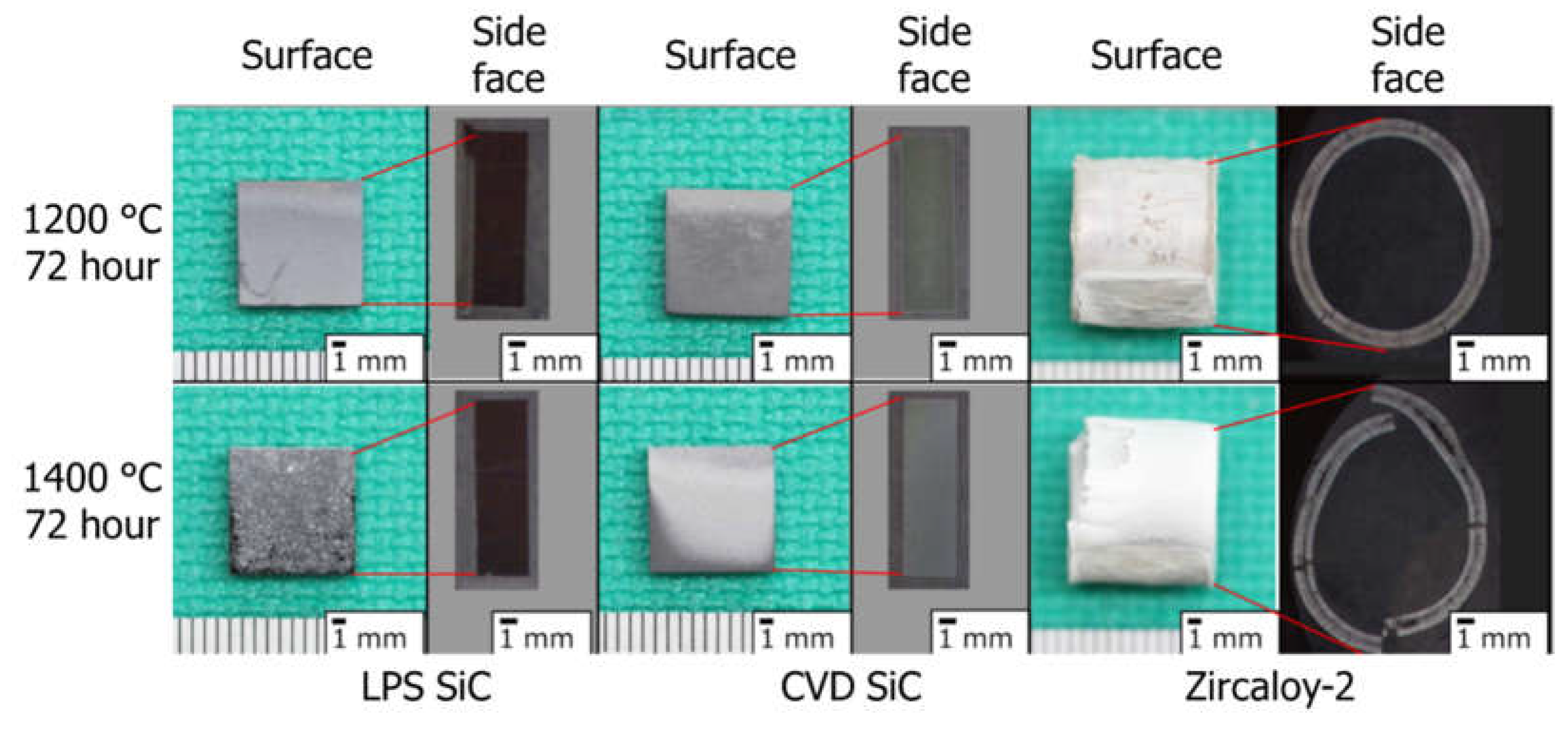
Figure 1. High-temperature steam oxidation behavior of the LPS SiC, the CVD SiC, and the Zircaloy-2 following steam oxidation for 72 h at 1200 and 1400 °C.
Coatings 12 00623 g001
Figure 2. SEM images of cross-section of the CVD SiC and the LPS SiC following steam oxidation for 72 h at 1200 °C.
Coatings 12 00623 g002
Figure 3. SEM images of cross-section of the CVD SiC and the LPS SiC following steam oxidation for 72 h at 1400 °C.
Coatings 12 00623 g003
Figure 4. The phase diagram of the Y2O3-Al2O3-SiO2 system, including isotherms at every 50 °C from 1400 °C by colored lines.
Coatings 12 00623 g004
Figure 5. Measured from SEM images and assumed weight changes of the CVD SiC and the LPS-SiC following steam oxidation for 72 h at 1200 and 1400 °C.
Coatings 12 00623 g005
Figure 6. A SEM image of the LPS SiC following high-temperature water corrosion (8 ppm dissolved oxygen, 20 MPa, 360 °C, and 168 h).
Coatings 12 00623 g006
Figure 7. Corrosion mass changes of the LPS SiC, the modified LPS SiC, YAG, and CVD SiC following high-temperature water corrosion (2 ppm dissolved oxygen, 20 MPa, 320 °C, and 168 h).
Coatings 12 00623 g007
Figure 8. SEM images of the LPS SiC (a) and the modified LPS (b) surfaces following high-temperature water corrosion (2 ppm dissolved oxygen, 20 MPa, 320 °C, and 168 h).
Coatings 12 00623 g008
Figure 9. XPS spectrum of the modified LPS before and following high-temperature water corrosion (2 ppm dissolved oxygen, 20 MPa, 320 °C, and 168 h).
Coatings 12 00623 g009
Figure 10. The LPS SiC composite tube fabrication utilizing the braiding technique.
Coatings 12 00623 g010
Figure 11. The monolithic SiC ceramic tubes and the LPS SiC composite tube before and after the thermal shock tests (1200 °C for 30 min to ambient temperature).
Coatings 12 00623 g011
Publisher’s Note: MDPI stays neutral with regard to jurisdictional claims in published maps and institutional affiliations.