Abstract
Ni0.95Fe0.05/NiFeO multilayers were fabricated by radio frequency magnetron sputtering and natural oxidation. Doping of Ni by only 5 at. % Fe results in enhanced layering quality as X-ray reflectivity reveals. Due to magnetostatic anisotropy, the multilayers were found to be in-plane magnetized. The influence of mild thermal annealing (T = 525 K) on the magnetic properties of NiFe/NiFeO multilayers is also investigated. Annealing results in the enhancement of perpendicular magnetic anisotropy, mainly due to an increase in the uniaxial volume anisotropy term. Temperature-dependent hysteresis measurements between 4–400 K revealed considerable enhancement of coercivity and appearance of exchange bias effect.
Keywords:
coatings; thin films; growth; sputtering; magnetic multilayers; magnetic anisotropy; exchange bias; NiFeO 1. Introduction
Magnetic anisotropy at metal/oxide interfaces has played a significant role in the development of technological applications such as magnetic recording, spintronics, sensors and actuators over the years [1,2,3,4,5]. More specifically, perpendicular magnetic anisotropy (PMA) has been observed in these systems despite the weak spin-orbit interactions at the interfaces [6,7,8]. This PMA is assumed to be the result of electronic hybridization over the interface between the oxygen and the magnetic transition metal orbit, according to ab initio calculations [1]. PMA in ultrathin magnetic layers is affected by two factors: surface anisotropy (KS) owing to the decreased symmetry at surfaces and interfaces and magnetoelastic anisotropy due to strain-induced crystallographic distortions [9,10].
With the use of a single magnetron sputtering head and natural oxidation, we recently demonstrated an efficient technique to produce Ni/NiO and NiCo/NiCoO multilayers with excellent stacking at the nanoscale and an ultrathin amorphous oxide layer of constant thickness (of about 1.4 ± 0.2 nm) [11,12,13]. The Ni/NiO system showed a tendency for perpendicular magnetic anisotropy due to strain and magnetoelastic anisotropy contributions. An even stronger tendency for PMA in both systems has been observed after mild thermal treatment [13,14]. Here, the PMA enhancement is due to partial crystallization of NiO layers after annealing [14].
In this work, we study the effects of Fe doping on the magnetic properties of Ni/NiO multilayers. The nickel-iron system has been widely examined. This alloy, depending on the composition, exhibits several magnetic properties that are desirable for applications [15]. Vas’ko and Kief reported that NiFe/NiFeO magnetic superlattices could show important electrical and magnetic properties: they could control the resistivity, saturation magnetization, magnetic anisotropy and permeability by changing the thickness of the NiFe layers [16]. The oxide NiFeO is an antiferromagnet with a rocksalt structure [17]. However, Wang et al. observed room-temperature (RT) ferromagnetism in Fe-doped NiO due to the composition inhomogeneity of ferromagnetic clusters and ferromagnetic/antiferromagnetic coupling [18]. Furthermore, a small exchange coupling was found in similar systems [17,19,20,21]. The exchange bias (EB) effect was discovered by Meiklejohn and Bean [22] and relates to the magnetic coupling across the common interface shared by a ferromagnetic (F) and an antiferromagnetic (AF) layer. The EB effect refers to the zero-field axis shift of the hysteresis loop in either a negative or positive direction regarding the applied field [23].
Here, radio frequency magnetron sputtering was used to deposit ultrathin Ni0.95Fe0.05 films under low argon pressure (2 × 10⁻³ mbar). They were transformed into Ni0.95Fe0.05/NiFeO multilayers via a periodic natural oxidation procedure (partial pressure of air ~2 × 10⁻³ mbar). X-ray reflectivity (XRR) revealed excellent layer sequencing with low roughness. Magneto-optic Kerr effect (MOKE) measurements were used for magnetic characterization and found that the systems were always in-plane magnetized in the as-deposited state. Some of them showed inverted hysteresis loops with the magnetic field being applied perpendicular to the film plane [24]. After a soft thermal treatment, however, the multilayers exhibit a relatively strong tendency for PMA. On the other hand, the exchange bias effect and strong coercivity enhancement were observed with the field applied in- and out-of-plane at low temperatures after field cooling.
2. Materials and Methods
Thin NiFe alloy multilayers were grown on Si(001) and Corning glass wafers by a radio-frequency (RF, the Torus 2 HV circular sputtering source of Kurt J. Lesker Company, Jefferson Hills, PA, USA) magnetron sputtering head (operating at 30 W). The vacuum chamber used for the deposition had a base pressure of about 3 × 10⁻⁷ mbar and the Ar pressure was kept constant for all the multilayers at 3 × 10⁻³ mbar. The deposition rate of 0.1 nm/s was monitored via a quartz balance system (Inficon XTM/2). For the formation of Ni0.95Fe0.05/NiFeO alloy multilayers, a Ni foil with small holes and a Fe foil with 99.99% purity, respectively, were used in a single sputtering head. This method is described in detail in Ref. [25]. The samples’ composition was evaluated using energy-dispersive X-ray spectroscopy (EDS, ZEISS, Oberkochen, Germany). The EDS equipment, which was integrated into a scanning electron microscopy (SEM, ZEISS, Oberkochen, Germany) setup, revealed only the presence of Fe and Ni. At the end of the deposition of each NiFe layer, air was introduced into the chamber via a leak valve at 2–3 × 10⁻³ mbar partial pressure for 1 min. On top of the NiFe layer, a thin saturated layer of NiFeO with a thickness of ~1.4 nm was created using this natural oxidation procedure. This method was repeated N times, where N is the number of multilayer periods desired. The aforementioned process was used to fabricate a series of eight NiFe/NiFeO multilayers with 6–23 repetitions and a total thickness in the 40–50 nm range [12]. The thickness tNiFe of the individual NiFe layers ranged from 0.8 to 5.1 nm. The number of repetitions N and the individual NiFe layer thickness tNiFe in each period are provided in Table 1.

Table 1.
Structural details of investigated Ni0.95Fe0.05/NiFeO multilayers in the as-deposited state. The five columns contain: (i) the thickness tNiFe of the individual NiFe layer in each multilayer period, (ii) the total film thickness t expressed as N × Λ, where N is the number of repetitions and Λ the thickness of one period of the multilayer, (iii) the total film thickness t expressed in nm, (iv) the RMSNiFe is the roughness of the NiFe layers determined by GenX and (v) the RMSNiFeO is the roughness of the oxide layers determined by GenX. The oxide layer tNiFeO is about 1.4 ± 0.2 nm.
Structural characterization of multilayers and the layering quality was performed with the aid of the X-ray reflectivity (XRR, recorded with a Bruker, D8-Advance, Karlsruhe, Germany) technique and via atomic force microscopy (AFM, Bruker, Santa Barbara, CA, USA). X-ray reflectivity (XRR) measurements were carried out in a Bede D1 X-ray diffractometer equipped with a Cu X-ray source operated at 35 mA and 50 kV, a Göbel mirror and a two-bounce-crystal on the incidence side. Moreover, a circular mask (5 mm), as well as an incidence and a detector slit (both 0.5 mm), were used. The X-rays were detected with a Bede EDRc X-ray detector (Bruker, D8-Advance, Karlsruhe, Germany). One pure NiFe film was characterized by atomic force microscopy (AFM) to determine the morphology and roughness of the surface of the NiFe itself, as the corresponding values for the multilayers were determined by XRR. The experiment was carried out by a Multimode Microscope controlled by Nanoscope IIIa (model AS-130VMF). It is equipped with a 120 × 120 μm2 magnet-free scanner (AS-130VMF,) developed by Bruker (Santa Barbara, CA, USA). The microscope was handled in the non-contact mode [26].
Magnetic characterization of the multilayers was achieved by recording hysteresis loops with a maximum external field of 12 kOe at RT via a magneto-optic Kerr effect (MOKE) magnetometer (Home-made) in two directions, polar (field normal-to-film plane) and longitudinal (field parallel-to-film plane) configurations [27]. The magnetic properties of films were also measured with a Quantum Design SQUID VSM magnetometer (Quantum Design, Darmstadt, Germany) in applied fields of up to 9.5 kOe in the temperature range of 4–300 K. The measurement protocol included initially cooling down to 4 K in the maximum field. The magnetic hysteresis loop then went from +maximum saturation field to -maximum field and back to +maximum field. Then the next temperature was set in the maximum field and a hysteresis loop was recorded in the same way. In such a way, we excluded any experimental factor that could influence the magnetization reversal [13].
3. Results
3.1. Multilayer Structural Characterization
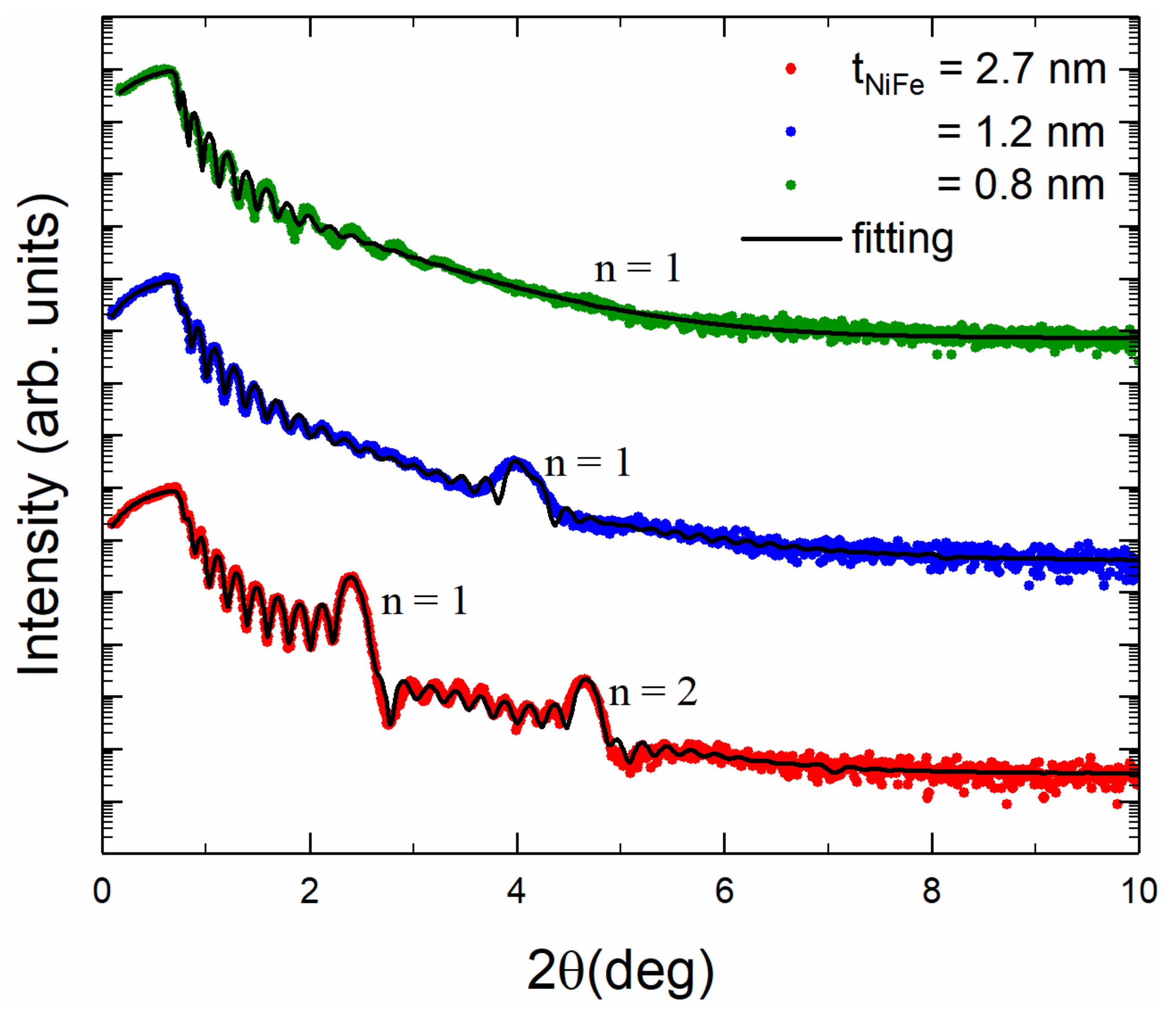
The X-ray reflectivities for three different samples in the as-deposited state are shown in Figure 1. The NiFe/NiFeO multilayers consist of N = 21, 17 and 10 repetitions and have tNiFe = 0.8, 1.2 and 2.7 nm, respectively. The thickness of the multilayer period can be estimated from the relative positions of the multilayer (Bragg) peaks labeled with a natural number “n” [28], whereas the total thickness of the film can be extracted from the Kiessig fringes, which are located between the multilayer peaks [29]. The presence of Kiessig fringes indicates a small surface roughness (see Figure 1). With the help of the GenX code [30], fittings of the XRR patterns were performed in order to deduce quantitative information. The fitting shows that for NiFe tNiFe = 2.7 and 1.2 nm, the root mean square roughness (Rrms) possesses relatively small values of 0.42 and 0.62 nm, respectively. For the sample with tNiFe = 0.8 nm and 21 repetitions, the value of Rrms is 0.99 nm. This indicates that the periodicity has slightly degraded by decreasing tNiFe.

Figure 1.
XRR patterns for three NiFe/NiFeO multilayers with 21 (green), 17 (blue) and 10 (red) repetitions (colored data points). All samples have a total thickness of about 40–50 nm. The fitted patterns using the GenX code are also shown as continuous lines). From the fitting, the tNiFeO was found to be 1.4 ± 0.2 nm.
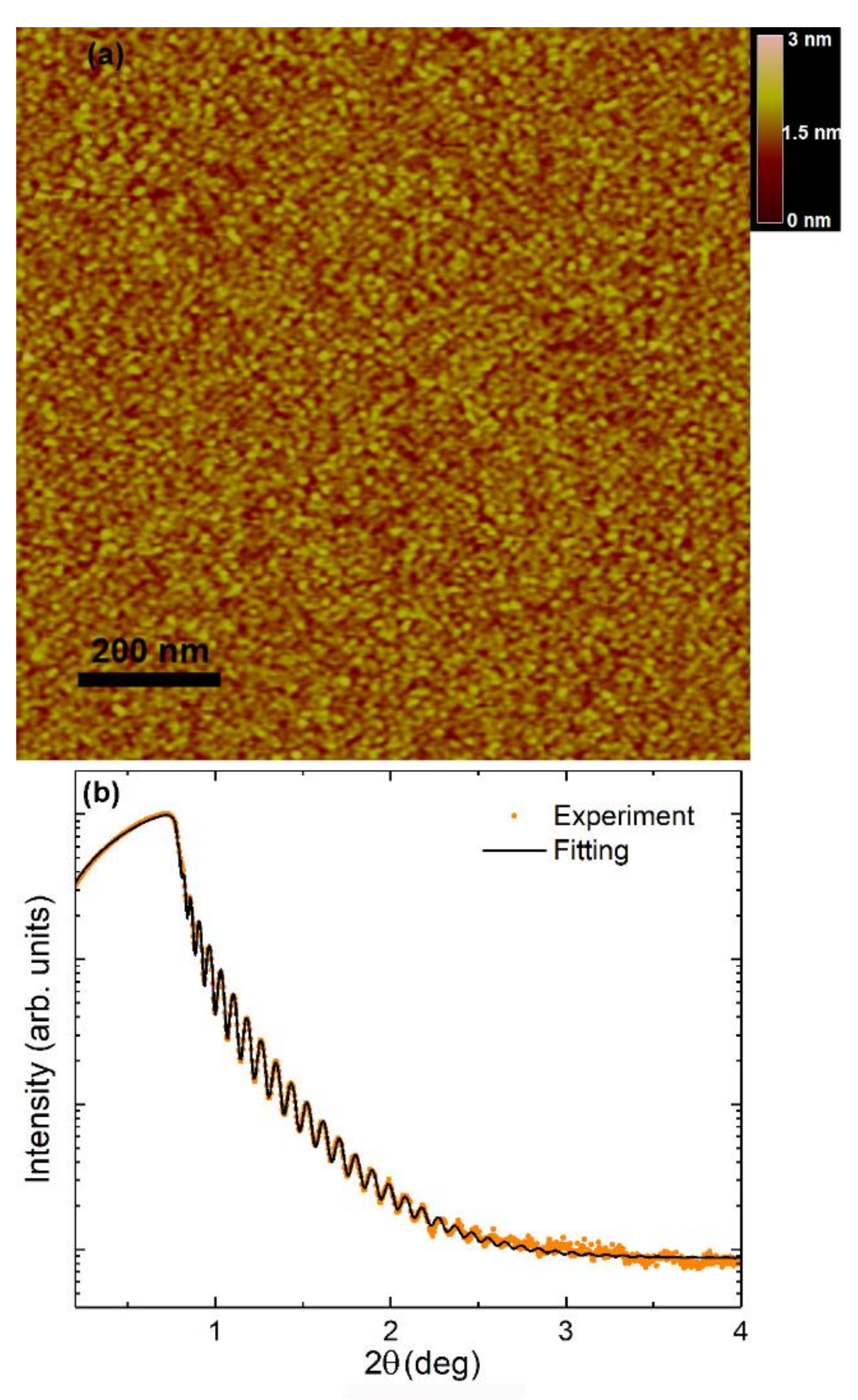
Figure 2a shows the surface of a single NiFe film with thickness t = 84 nm recorded by atomic force microscope. The grain diameter is about 20 nm large and quite homogeneous in terms of size. The surface is very smooth, with an Rrms roughness of only 0.26 nm. However, if one attempts to fit the XRR data for the same sample via GenX (Figure 2b), one ends up with Rrms = 0.78 nm. The AFM value may be underestimated due to the finite radius of the AFM tip. However, both extracted RMS (GenX and AFM) values are surprisingly small for such thick films.
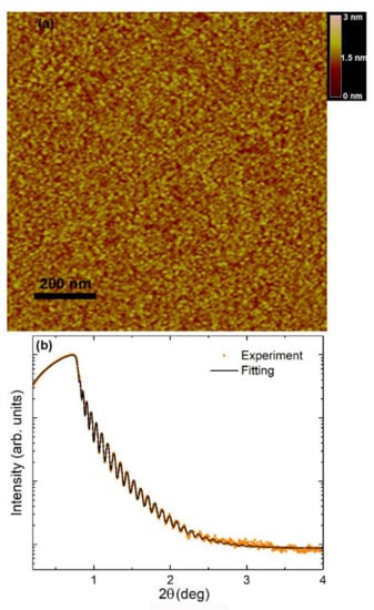
Figure 2.
(a) AFM image of the surface of a single NiFe thin film with t = 84 nm. Color scalebar to show roughness is added. (b) XRR pattern.
The small roughness of the surfaces indicates the high quality of the multilayer interfaces, which is desirable when interlayer coupling is investigated. It is important to notice that in Ni/NiO multilayers, the layering already degrades considerably when tNi decreases below 2.5 nm [12]. Adding only 5 at % of Fe in this system results in improved layering to such an extent that even the sample with tNiFe = 1.2 nm shows a small-angle Bragg peak (Figure 1). By taking into account the results of Table 1, Rrms seems to increase by decreasing the NiFe layer thickness. This might sound unusual. However, one has to recall that a smaller thickness of NiFe layers means an increase in the number of bilayers. This, in turn, leads to some accumulation of roughness. A similar result has been also observed in pure Ni/NiO multilayers [12].
3.2. Magnetic Characterization
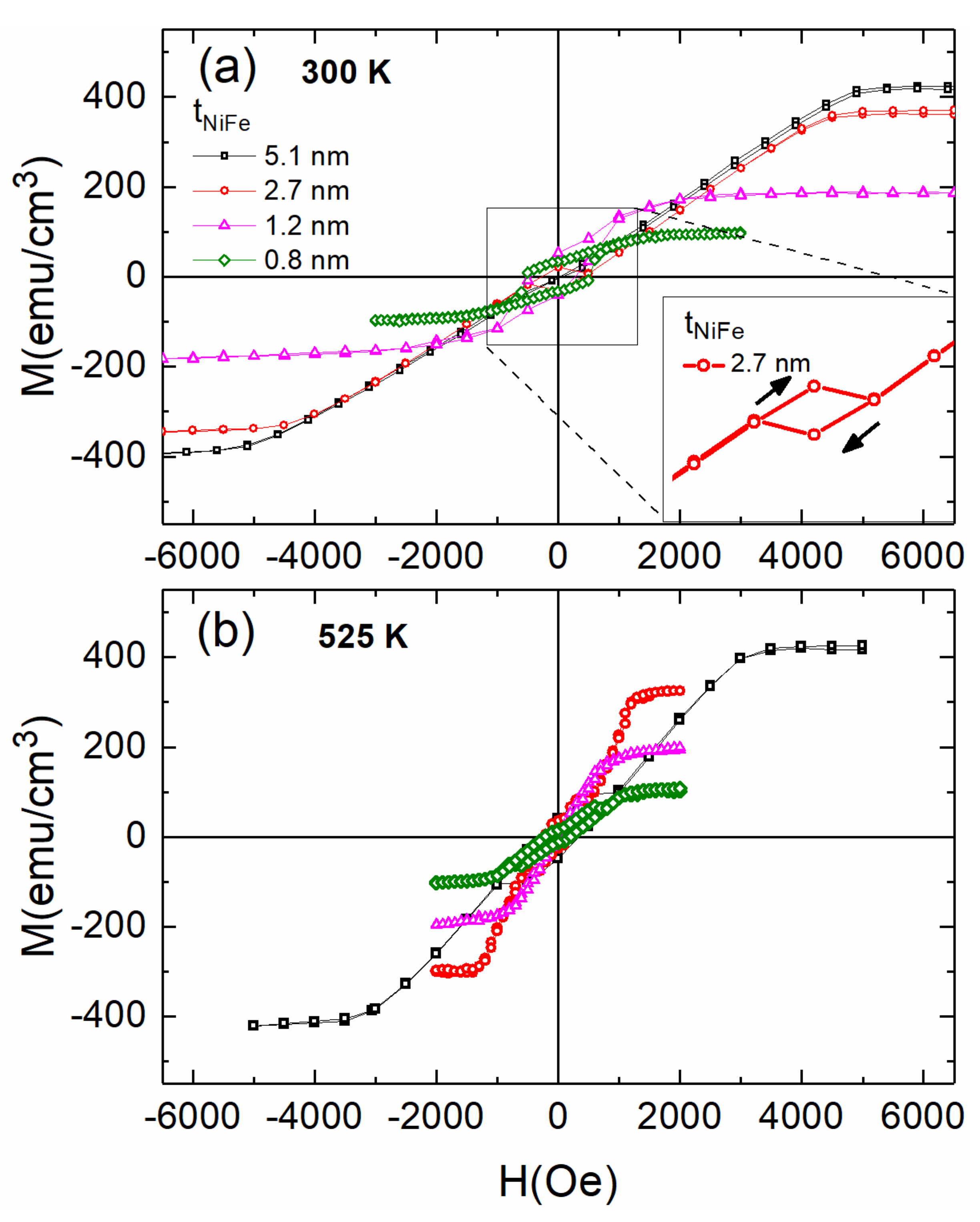
Figure 3 shows polar-MOKE magnetic hysteresis loops for four Ni0.95Fe0.05/NiFeO multilayers before Figure 3a and after annealing Figure 3b. These loops exhibit hard-axis behavior. The calibration of the Y-axis was done in a similar way as the one described in Ref. [8]. In the as-deposited state (300 K), the hysteresis loops in the polar geometry become broader as the film thickness decreases. The coercivity increases up to 0.6 kOe for the sample with 21 repetitions and tNiFe = 0.8 nm. A multilayer with tNiFe = 2.7 and 10 repetitions shows an inverted hysteresis loop with negative remanence when the magnetic field is applied perpendicular to the film plane, as depicted in the inset of Figure 3a. This phenomenon in our system may be due to antiferromagnetic coupling [24,31,32,33]. We have treated this matter quantitatively in Ref. [25]. For multilayers with relatively thick NiFe layers, tNiFe = 5.1 nm, the saturation field HS is close to 5 kOe; this decreases by decreasing tNiFe. This finding implies that the samples have a weak PMA trend as compared to net Nickel films. Indeed, a net Nickel film with only magnetostatic anisotropy would present a saturation field Hs = 4πM~6 kOe. The samples are thermally annealed at 525 K for 90 min. One may observe considerable changes in saturation and coercivity, Figure 3b. More specifically, the saturation field Hs has been strongly decreased by about 2.5 kOe for the multilayer with tNiFe = 5.1 nm. The increase in the coercivity in the perpendicular field together with a decrease in the saturation field is indicative of the development of PMA. However, this does not occur for the thinnest sample with tNiFe = 0.8 nm. This corresponds to a thickness of only four atomic layers. These ultrathin layers may deteriorate after annealing and in such a case, the loops tend to be anhysteretic. Such a loss of layering together with decreased remanence and coercivity has been investigated in detail in Ref. [12] by a combination of SQUID magnetometry and High Resolution Transmission Electron Microscopy.
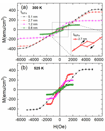
Figure 3.
RT polar MOKE hysteresis loops (H is applied along the film normal) for four NiFe/NiFeO multilayers with tNiFe as indicated, before (a) (top) and after annealing at 525 K for 90 min (b). In the inset, the magnification of the data near zero magnetic field for a sample with tNiFe = 2.7 nm is shown, which presents inverted hysteresis with negative remanence.
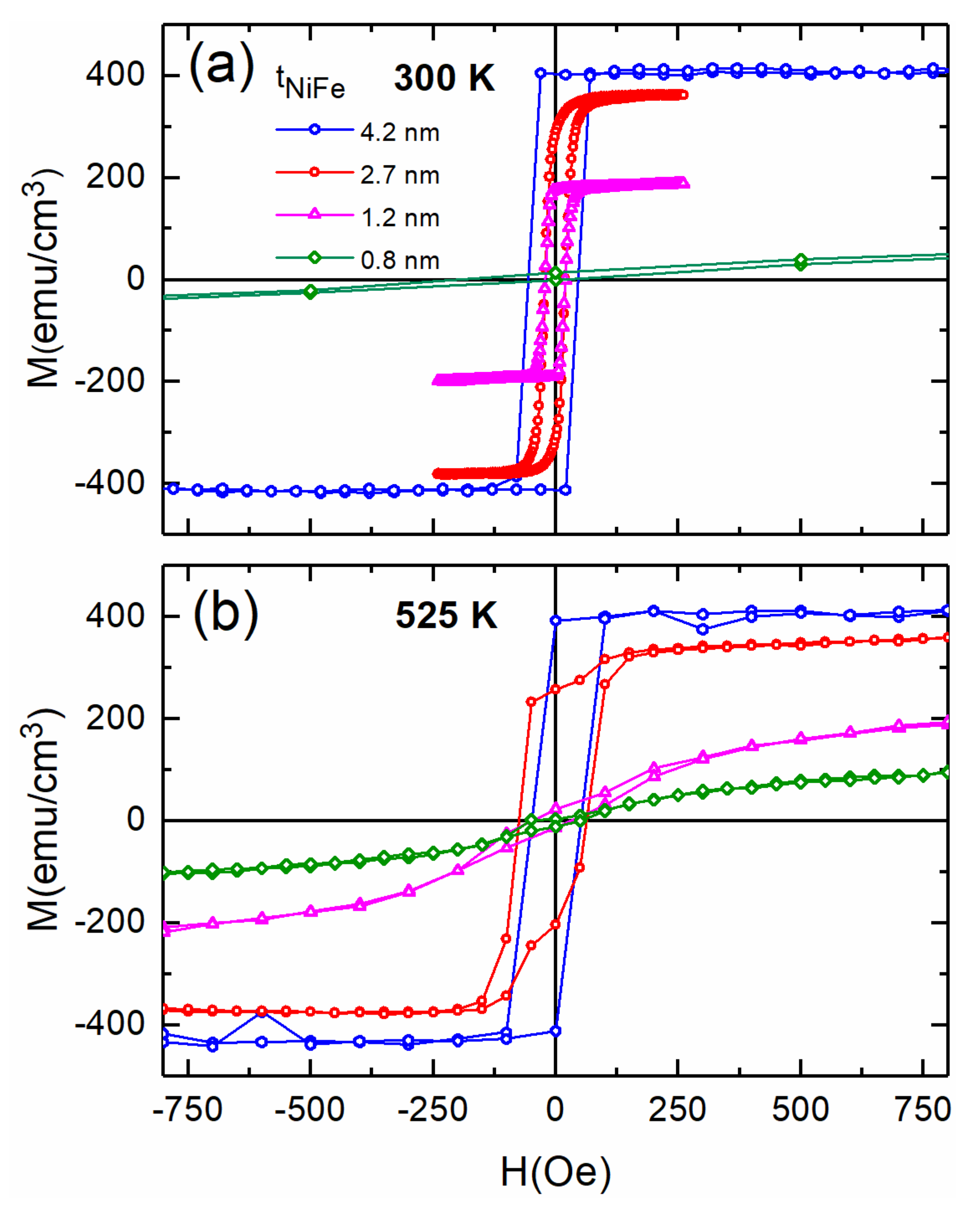
In Figure 4, longitudinal-MOKE hysteresis loops are shown for four multilayers with N = 7–23 Figure 4a before and Figure 4b after annealing for 90 min at 525 K. These multilayers have tNiFe in the range of 0.6–3.9 nm. At RT, the majority of the films present typical easy-plane anisotropy with 100% remanence, and the saturation is completed at about 0.05 kOe at maximum, Figure 4a. As Figure 4b reveals, there are changes in the shape of the hysteresis loops after annealing. Most of the samples have decreased remanence, while the coercivity has been slightly increased compared to the one in the as-deposited state. The substantial difference between these loops before and after annealing implies that Keff changes significantly, (Figure 5) and results in the tendency of PMA enhancement. Similar behavior was detected in Ni/NiO multilayers with a dopant of Co of the order of 10% at. [13].

Figure 4.
RT longitudinal MOKE hysteresis loops (H is applied parallel to the film plane) for four NiFe/NiFeO multilayers with tNiFe as indicated before (a) and after annealing at 525 K for 90 min (b).
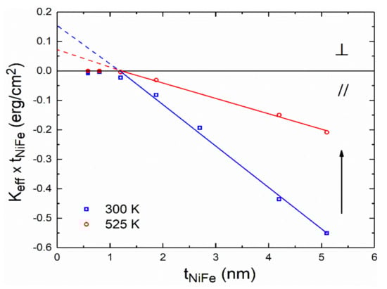
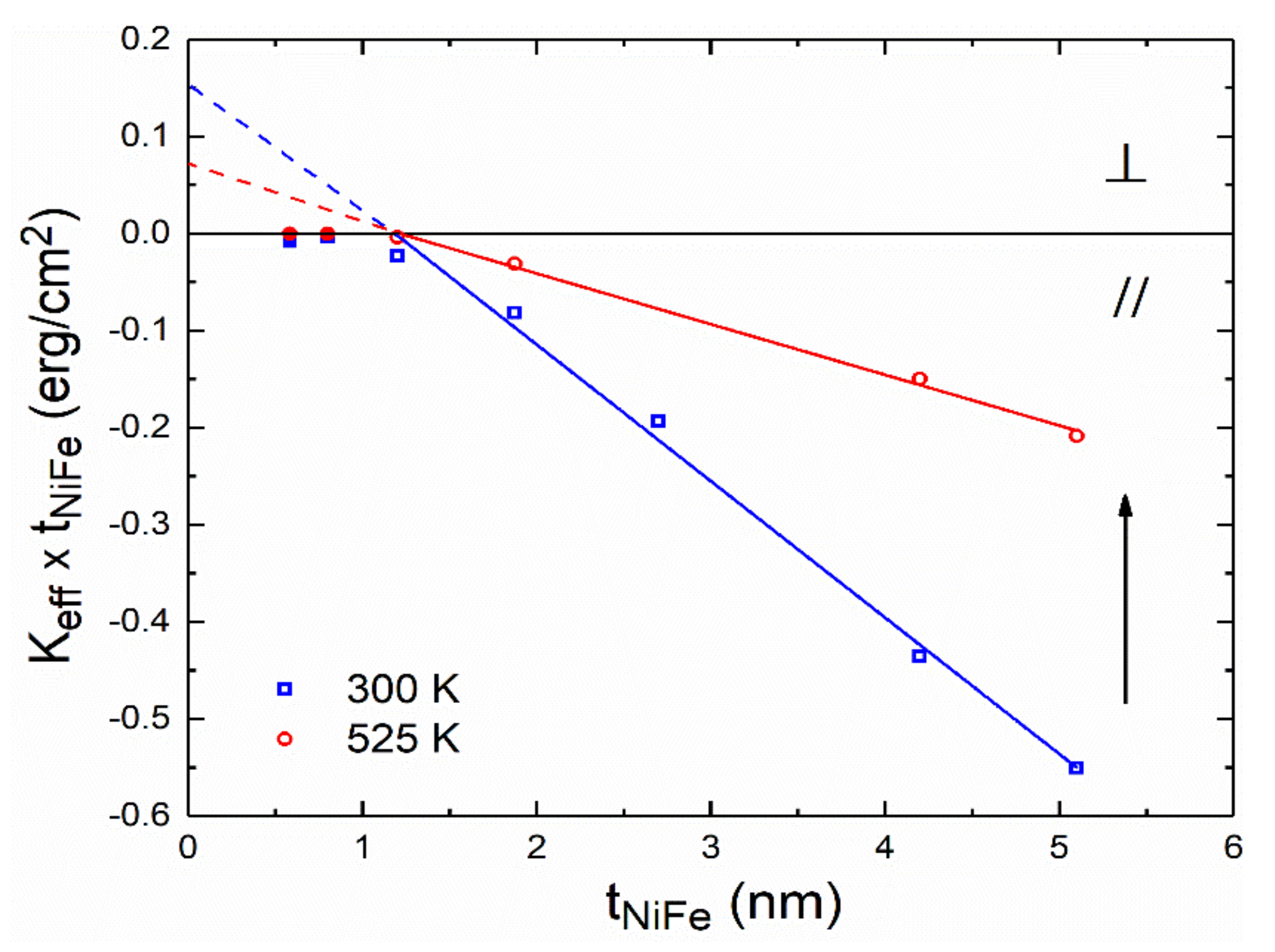
Figure 5.
Dependence of the effective magnetic anisotropy constant Keff × tNiFe on tNiFe, for NiFe/NiFeO multilayers at room temperature (open rectangular) and after annealing at 525 K for 90 min (open circles) for all multilayers of Table 1. The arrow indicates the shift on the slope of the plot for the annealed samples. For the quantitative analysis of this plot, we have used only data for multilayers with continuous magnetic layers, that is, tNiFe > 1 nm.
The magnetic anisotropy Keff per unit volume of magnetic layers with thickness t can be represented as the sum of a volume and an interface term in a phenomenological model [34]:
where magnetocrystalline, magnetostatic, and magneto-elastic anisotropy all contribute to KV, while interface anisotropy is represented by KS [34]. We can derive the KV value from the line’s slope, as well as the Ks value from the line’s intercept with the perpendicular axis, by applying this analysis to our experimental data points with tNiFe down to 1 nm. In this case, the experimental data points were obtained only from MOKE measurements on unannealed samples and samples annealed at 525 K. For the NiFe/NiFeO multilayers at 300 K, KS = 0.084 ± 0.010 erg/cm2 and KV = (−1.40 ± 0.06) × 106 erg/cm3. After annealing at 525 K for 90 min, the plot of the data of Keff over tNiFe showed a drastic change in both the slope of the line and the values of KS and KV. More specifically, Ks decreased to 0.032 ± 0.004 erg/cm2 and KV to (−0.52 ± 0.02) × 106 erg/cm3. We observe a small decrease in the interface anisotropy, which may be due to the increase in the layer roughness after annealing [35]. However, the volume anisotropy has decreased by more than a factor of two. The negative sign favors in-plane anisotropy. Consequently, a strong tendency towards PMS after annealing is obvious. These results are quite similar to Ni/NiO multilayers [14]. On the other hand, the Ni0.9Co0.1/NiCoO system did not present such a large enhancement of PMA after annealing [13].
Keff * tNiFe = KV * tNiFe + 2KS
In order to further study the magnetic anisotropy behavior, we have performed temperature-dependent magnetization hysteresis loops with the help of SQUID magnetometry for the thickest and thinnest NiFe layers with the best multilayer quality.
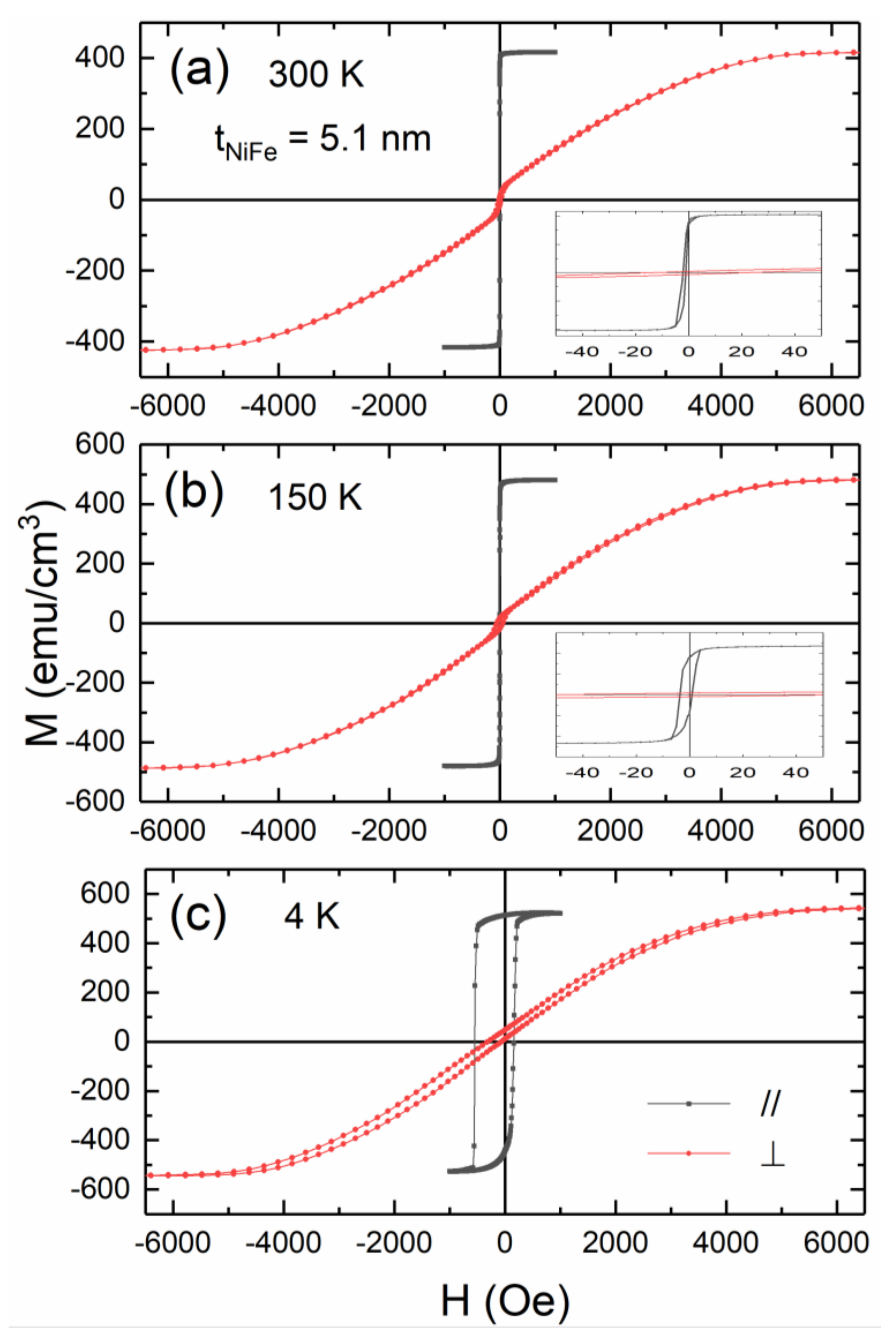
In Figure 6, we plot the temperature-dependent magnetization hysteresis loops for the multilayer with tNiFe = 5.1 nm and 6 repetitions. The loops were recorded by SQUID with the external field perpendicular and parallel to the film plane, as indicated. At 4 K, M is about 540 emu/cm3 (larger than the one of the bulk Ni which is 510 emu/cm3 due to the addition of Fe doping). M at room temperature is slightly larger than 400 emu/cm3 but less than the 480 emu/cm3 of bulk Ni. This occurs because ultrathin layers usually show a stronger temperature dependence of the magnetization than the bulk materials due to space-reduced spin wave excitations and finite size effects [10]. At all temperatures, this sample saturates easier on the film plane; thus, it shows in-plane anisotropy. However, the loops with the field applied along the film normal are not typical hard-axis loops. Those typical loops should not show any hysteresis and be linear between zero and saturation field [36]. The sigmoidal approach to saturation and the rather abrupt magnetization switch near zero field (especially at 150 K and 300 K) remind us of hard-axis loops when the system has higher-order anisotropy contributions and/or cone states, see e.g., [37,38].

Figure 6.
Temperature-dependent magnetization hysteresis loops with the external field applied perpendicular (red circles) and parallel (black circles) to the film plane for a NiFe/NiFeO multilayer with tNiFe = 5.1 nm and 6 repetitions for 300 K (a), 150 K (b) and 4 K (c). The inset in Figure 6 is a magnified plot near zero field for better clarity.
At 4 K, Figure 6c, the loop with the external field applied normal to the film plane exhibits a significant increase in coercive field, (HC), of approximately 330 Oe and an exchange field (HEB) of approximately 200 Oe. We have to notice that the 4 K loops are both exchange-shifted indicating a coupling between the NiFe and NiFeO layers. In Figure 7 we attempted to fit the 4 K hysteresis loop with the field applied along the film normal (experimental data points). We considered a single-domain Stoner–Wohlfarth-like model, measuring the angles from the film normal [25]. In this theoretical framework, positive values of uniaxial anisotropy favor PMA. Before attempting to fit the experimental data, we shifted the hysteresis curves slightly to the right in order to cancel the exchange bias effect. The various models we used to describe the fitting considered just the term of magnetostatic anisotropy (2πM2) for the first case, the terms of magnetostatic anisotropy and the uniaxial anisotropy Ku1 = 9 × 10⁵ erg/cm3 for the second case. The third model is considered in terms of magnetostatic anisotropy, the uniaxial Ku1 = 7.5 × 10⁵ erg/cm3, and the biaxial Ku2 = Ku1/5 = 1.5 × 10⁵ erg/cm3 anisotropy. However, the best fitting and the only one which produces hysteresis is achieved when one considers that the uniaxial anisotropy axis is not the film normal but an easy cone with β = 2.5° inclination of its slant height with respect to the film normal. We think that this may have a structural origin. For Ni/NiO multilayers, transmission electron microscopy has revealed {111} texture [6]. A small-angle deviation from this, for example, due to a small misplacement of the sample holder, could have resulted in crystallites with a distribution of axis slightly tilted from the {111}. This, in turn, could have resulted in a slight tilting of the uniaxial anisotropy axis [39,40,41].
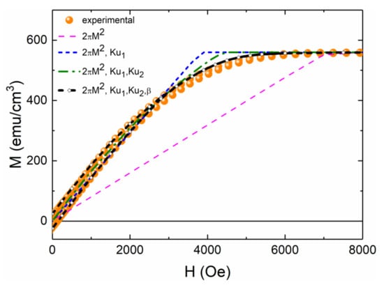
Figure 7.
4 K experimental M(H) data points and theoretically produced curves including various anisotropy terms as indicated. The magnetic field is placed along the film normal.
In Figure 8 we plot the temperature dependence of the magnetization, Keff and the quantity Ku1 + Ku2 = 2πM2 + Keff; the first term includes volume and surface uniaxial anisotropy. All values are normalized by dividing them by the corresponding absolute value at 4 K. Keff is negative, favoring in-plane anisotropy. In the same plot, we have introduced the normalized M3 and M4 curves. The Ku1 + Ku2 term shows a fast decay with temperature. For comparison, we plot the M3(T) and M4(T) terms. According to Callen and Callen [42], a uniaxial anisotropy term should show a temperature dependence proportional to M3(T). This holds well for lower temperatures, Figure 8. However, near room temperature, the Ku1 + Ku2 term decays faster than M4(T). This shows a more significant contribution of high-order anisotropy terms, see also [12]. This effect manifests itself in the hard axis loops of Figure 6 where, with increasing temperature, the remanence also increases. This rather unusual behavior may be understood by the fact that the Ku2 is related to the aforementioned slight misorientation of crystallites from the film normal, which, obviously, is not temperature-dependent.
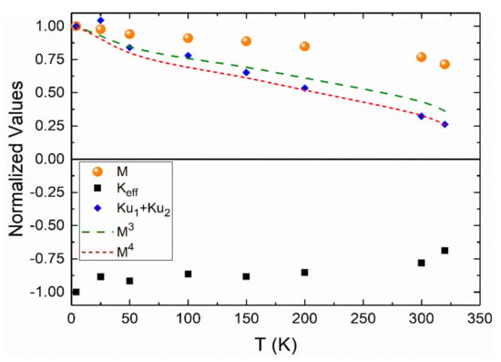
Figure 8.
Temperature-dependent magnetizations and anisotropies, as indicated, for the multilayer with tNiFe= 5.1 nm.
In Figure 9, we plot the SQUID hysteresis loops for a NiFe/NiFeO multilayer with a thin magnetic layer tNiFe = 1.8 nm and 13 repetitions. At a low temperature of 4 K, the hysteresis loop with applied field parallel to the film plane is not as rectangular as at 300 and 150 K, and the perpendicular loop has an important increase in remanence compared to the multilayer of Figure 6.
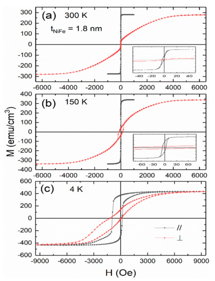
Figure 9.
Temperature-dependent magnetization hysteresis loops with the external field applied perpendicular (red circles) and parallel (black circles) to the film plane for a NiFe/NiFeO multilayer with tNiFe = 1.8 nm and 13 repetitions for 300 K (a), 150 K (b) and 4 K (c). The inset in Figure 9 is a magnified plot near-zero field for better clarity.
In Figure 10 we plot the temperature dependence of the magnetization and the effective anisotropy for the film with tNiFe = 1.8 nm. All values are normalized by dividing them by the corresponding absolute value at 4 K. One may add two notes: (a) The magnetization exhibits a stronger temperature dependence than one of the samples with tNiFe = 5.1 nm. This is due to finite-size effects [10], as the thickness of 1.8 nm is quite small. (b) The absolute value of Keff shows a very intense increase at very low temperatures. We did not attempt to evaluate Ku1 + Ku2 from the area between the easy and hard magnetization axis, as this strong increase of Keff could be due to some strong antiferromagnetic coupling.
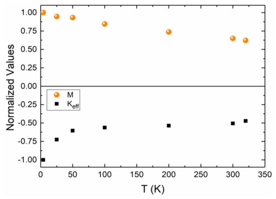
Figure 10.
Temperature-dependent magnetizations and anisotropies, as indicated, for the multilayer with tNiFe = 1.8 nm.
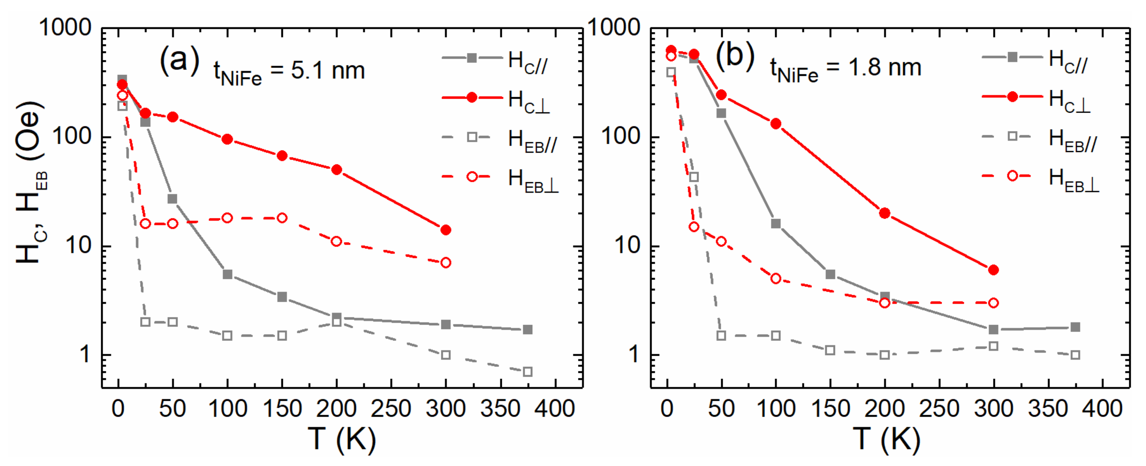
Compared to the previous sample with the thickest magnetic layers, this multilayer shows a significant enhancement in coercive and exchange field of about 580 and 400 Oe, respectively. This may be better visualized in Figure 11; we plot the coercive HC and exchange HEB field for the parallel and perpendicular applied field for (a) the multilayer with tNiFe = 5.1 nm and (b) the multilayer with tNiFe = 1.8 nm. The multilayer with the thinnest layer is magnetically harder. It has a stronger tendency for PMA and exhibits a larger exchange bias effect. This renders it more interesting for novel applications. However, overall, PMA, HC and HEB are somehow smaller as compared to Ni/NiO multilayers with Co doping [13].
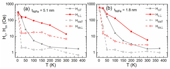
Figure 11.
Temperature-dependent coercive and exchange fields for two multilayers with tNiFe = 5.1 nm (a) and tNiFe = 1.8 nm (b) as indicated.
4. Conclusions
In this work, we study the magnetic properties of Ni0.95Fe0.05/NiFeO multilayers before and after annealing in mild conditions in a furnace with air. The samples were deposited using an RF sputtering technique and demonstrated excellent layering with smaller roughness than the Ni/NiO ones, as revealed by XRR and AFM microscopy. At the as-deposited state, easy-plane behavior is seen in the samples, which is typical of polycrystalline magnetic thin films. The tendency for perpendicular magnetic anisotropy is relatively pronounced after annealing at temperatures up to 525 K. It was also evident from the drastic change in both the slope of the line and the values of KS and KV after annealing, as the plot of the data of Keff over tNiFe has shown. SQUID magnetometry was used to study temperature-dependent magnetizations, anisotropies and exchange bias for the thickest (tNiFe = 5.1 nm) and thinnest (tNiFe = 1.8 nm) NiFe layers. The multilayer with the thinnest layer is magnetically harder with a coercive field of HC = 620 Oe and exhibits a larger exchange bias effect, HEB = 400 Oe at 4 K.
Author Contributions
Conceptualization, P.P.; methodology, P.P., D.I.A. and E.T.P.; software, N.K., D.I.A. and V.K.; validation, P.P., E.T.P., V.K. and G.S.; formal analysis, D.I.A., A.B. and C.B.; investigation, D.I.A., N.K., A.B. and C.B.; resources, P.P., E.T.P., V.K. and G.S.; data curation, D.I.A. and C.B.; writing—original draft preparation, D.I.A.; writing—review and editing, P.P., E.T.P., V.K., N.K. and G.S.; visualization, P.P., E.T.P., V.K. and G.S.; supervision, P.P. and E.T.P.; project administration, P.P.; funding acquisition, D.I.A., P.P. and E.T.P. All authors have read and agreed to the published version of the manuscript.
Funding
The research work was supported by the Hellenic Foundation for Research and Innovation (HFRI) under the HFRI Ph.D. Fellowship Grant (Fellowship No. 1006). The work was supported by the bilateral German-Greek Collaboration scheme for the promotion of the exchange and scientific corporation, PPP-DAAD IKYDA 2020, Project number 57547336, Title: Antiferromagnetic spintronics using novel ferromagnetic/antiferromagnetic-oxide multilayer structures.
Institutional Review Board Statement
Not applicable.
Informed Consent Statement
Not applicable.
Data Availability Statement
Data sharing not applicable.
Acknowledgments
V. Karoutsos is acknowledged for the AFM image.
Conflicts of Interest
The authors declare no conflict of interest.
References
- Dieny, B.; Chshiev, M. Perpendicular magnetic anisotropy at transition metal/oxide interfaces and applications. Rev. Mod. Phys. 2017, 89, 025008. [Google Scholar] [CrossRef]
- Bibes, M.; Villegas, J.E.; Barthélémy, A. Ultrathin oxide films and interfaces for electronics and spintronics. Adv. Phys. 2011, 60, 5–84. [Google Scholar] [CrossRef]
- Felser, C.; Fecher, G.H.; Balke, B. Spintronics: A challenge for materials science and solid-state chemistry. Angew. Chem. 2007, 46, 668–699. [Google Scholar] [CrossRef]
- Baltz, V.; Manchon, A.; Tsoi, M.; Moriyama, T.; Ono, T.; Tserkovnyak, Y. Antiferromagnetic spintronics. Rev. Mod. Phys. 2018, 90, 015005. [Google Scholar] [CrossRef] [Green Version]
- Hirohata, A.; Yamada, K.; Nakatani, Y.; Prejbeanu, I.-L.; Dieny, B.; Pirro, P.; Hillebrands, B. Review on spintronics: Principles and device applications. J. Magn. Magn. Mater. 2020, 509, 166711. [Google Scholar] [CrossRef]
- Hirohata, A.; Frost, W.; Samiepour, M.; Kim, J. Perpendicular magnetic anisotropy in heusler alloy films and their magnetoresistive junctions. Materials 2018, 11, 105. [Google Scholar] [CrossRef] [Green Version]
- Lattery, D.M.; Zhang, D.; Zhu, J.; Hang, X.; Wang, J.-P.; Wang, X. Low gilbert damping constant in perpendicularly magnetized W/CoFeB/MgO films with high thermal stability. Sci. Rep. 2018, 8, 13395. [Google Scholar] [CrossRef] [Green Version]
- Gao, H.; Harumoto, T.; Luo, W.; Lan, R.; Feng, H.; Du, Y.; Nakamura, Y.; Shi, J. Room temperature perpendicular exchange bias in CoNi/(Co,Ni)O multilayers with perpendicular magnetic anisotropy directly induced by FM/AFM interface. J. Magn. Magn. Mater. 2019, 473, 490–494. [Google Scholar] [CrossRef]
- Heinrich, B.; Bland, J.A.C. Ultrathin Magnetic Structures I, 1st ed.; Springer: Berlin/Heidelberg, Germany, 1994; pp. 1–6. [Google Scholar]
- Poulopoulos, P.; Baberschke, K. Magnetism in thin films. J. Phys. Cond. Matt. 1999, 11, 9495–9515. [Google Scholar] [CrossRef]
- Poulopoulos, P.; Kapaklis, V.; Jönsson, P.E.; Papaioannou, E.T.; Delimitis, A.; Pappas, S.D.; Trachylis, D.; Politis, C. Positive surface and perpendicular magnetic anisotropy in natural nanomorphous Ni/NiO multilayers. Appl. Phys. Lett. 2010, 96, 202503. [Google Scholar] [CrossRef]
- Pappas, S.D.; Kapaklis, V.; Delimitis, A.; Jönsson, P.E.; Papaioannou, E.T.; Poulopoulos, P.; Fumagalli, P.; Trachylis, D.; Velgakis, M.J.; Politis, C. Layering and temperature-dependent magnetization and anisotropy of naturally produced Ni/NiO multilayers. J. Appl. Phys. 2012, 112, 053918. [Google Scholar] [CrossRef] [Green Version]
- Anyfantis, D.I.; Kanistras, N.; Ballani, C.; Barnasas, A.; Kapaklis, V.; Schmidt, G.; Papaioannou, E.T.; Poulopoulos, P. Magnetic aspects and large exchange bias of Ni0.9Co0.1/NiCoO multilayers. Micro 2021, 1, 43–54. [Google Scholar] [CrossRef]
- Anyfantis, D.I.; Sarigiannidou, E.; Rapenne, L.; Stamatelatos, A.; Ntemogiannis, D.; Kapaklis, V.; Poulopoulos, P. Unexpected development of perpendicular magnetic anisotropy in Ni/NiO multilayers after mild thermal annealing. IEEE Magn. Lett. 2019, 10, 1–5. [Google Scholar] [CrossRef]
- Swartzendruber, L.J.; Itkin, V.P.; Alcock, C.B. The FeNi (IronNickel) system. J. Phase Equilibria 1991, 12, 288–312. [Google Scholar] [CrossRef]
- Vas’Ko, V.A.; Kief, M.T. Structure and properties of NiFe/NiFeO magnetic superlattice. J. App. Phys. 2005, 97, 9–12. [Google Scholar] [CrossRef]
- Lai, C.-H.; Wang, C.P.; Qian, C. Orientation effect on the exchange fields of NiFeO/NiFe bilayers. J. App. Phys. 1999, 85, 4990–4992. [Google Scholar] [CrossRef]
- Wang, J.; Cai, J.; Lin, Y.-H.; Nan, C.-W. Room temperature ferromagnetism observed in Fe doped NiO. App. Phys. Lett. 2005, 87, 1–3. [Google Scholar] [CrossRef]
- Lai, C.-H.; Bailey, W.E.; White, R.L. Exchange anisotropy in NiFe/Fe doped NiO bilayers. J. App. Phys. 1997, 81, 4990–4992. [Google Scholar] [CrossRef]
- Qian, Z.; Sivertsen, J.M.; Judy, J.H. Magnetic behavior of NiFe/NiO bilayers. J. App. Phys. 1998, 83, 6825–6827. [Google Scholar] [CrossRef]
- Blachowicz, T.; Ehrmann, A. Exchange bias in thin films—An update. Coatings 2021, 11, 122. [Google Scholar] [CrossRef]
- Meiklejohn, W.H.; Bean, C.P. New magnetic anisotropy. Phys. Rev. 1956, 102, 1413. [Google Scholar] [CrossRef]
- Nogués, J.; Sort, J.; Langlais, V.; Skumryev, V.; Suriñach, S.; Muñoz, J.S.; Baró, M.D. Exchange bias in nanostructures. Phys. Rep. 2005, 422, 65–117. [Google Scholar] [CrossRef]
- Flevaris, N.K.; Krishnan, R. Modulation-induced effects in magnetic multilayers: Perpendicular anisotropy, reversed hysteresis and magnetization enhancement. J. Magn. Magn. Mater. 1992, 104–107, 1760–1762. [Google Scholar] [CrossRef]
- Anyfantis, D.I.; Kanistras, N.; Barnasas, A.; Poulopoulos, P.; Papaioannou, E.T.; Conca, A.; Trachylis, D.; Politis, C. Effects of thermal annealing and Ni addition on the magnetic properties of Co–CoO multilayers. SPIN 2020, 40, 2050030. [Google Scholar] [CrossRef]
- Karoutsos, V. Scanning probe microscopy: Instrumentation and applications on thin films and magnetic multilayers. J. Nanosci. Nanotechnol. 2009, 9, 6783–6798. [Google Scholar] [CrossRef] [PubMed]
- Kapaklis, V.; Pappas, S.D.; Poulopoulos, P.; Trachylis, D.; Schweiss, P.; Polotis, C. Structure and magnetic properties of hcp and fcc nanocrystalline thin Ni films and nanoparticles produced by radio frequency magnetron sputtering. J. Nanosci. Nanotechnol. 2010, 10, 6024–6028. [Google Scholar] [CrossRef]
- Poulopoulos, P.; Angelakeris, M.; Papaioannou, E.T.; Flevaris, N.K.; Niarchos, D.; Nyvlt, M.; Prosser, V.; Visnovsky, S.; Mueller, C.; Fumagalli, P.; et al. Structural, magnetic, and spectroscopic magneto-optical properties aspects of Pt–Co multilayers with intentionally alloyed layers. J. Appl. Phys. 2003, 94, 7662. [Google Scholar] [CrossRef]
- Kiessig, H. Untersuchungen zur totalreflexion von röntgenstrahlen. Ann. Phys. 1931, 402, 715–768. [Google Scholar] [CrossRef]
- Björck, M.; Andersson, G. GenX: An extensible X-ray reflectivity refinement program utilizing differential evolution. J. Appl. Crystallogr. 2007, 40, 1174–1178. [Google Scholar] [CrossRef]
- O’Shea, M.J.; Al-Sharif, A.-L. Inverted hysteresis in magnetic systems with interface exchange. J. Appl. Phys. 1994, 75, 6673. [Google Scholar] [CrossRef]
- Wu, Y.Z.; Dong, G.S.; Jin, X.F. Negative magnetic remanence in Co/Mn/Co grown on GaAs(001). Phys. Rev. B 2001, 64, 214406. [Google Scholar] [CrossRef] [Green Version]
- Haycock, P.W.; Chioncel, M.F.; Shah, J. Remanence studies of cobalt thin films exhibiting inverse hysteresis. J. Magn. Magn. Mater. 2002, 1057, 242–245. [Google Scholar] [CrossRef]
- den Broeder, F.J.A.; Hoving, W.; Bloemen, P.J.H. Magnetic anisotropy of multilayers. J. Magn. Magn. Mater. 1991, 93, 562–570. [Google Scholar] [CrossRef]
- De Jonge, W.J.M.; Bloemen, P.J.H.; den Broeder, F.J.A. Experimental investigations of magnetic anisotropy. In Ultrathin Magnetic Structures I, 2nd ed.; Springer: Berlin, Germany, 1994; pp. 65–90. [Google Scholar]
- Jiles, D. Introduction to Magnetism and Magnetic Materials, 1st ed.; Chapman and Hall: New Delhi, India, 2015. [Google Scholar]
- Fromter, R.; Stillrich, H.; Menk, C.; Oepen, H.P. Imaging the cone state of the spin reorientation transition. Phys. Rev. Lett. 2008, 100, 207202. [Google Scholar] [CrossRef] [PubMed]
- Timopheev, A.A.; Sousa, R.; Chshiev, M.; Nguyen, H.T.; Dieny, B. Second order anisotropy contribution in perpendicular magnetic tunnel junctions. Sci. Rep. 2016, 6, 26877. [Google Scholar] [CrossRef] [Green Version]
- Okamoto, T.; Itoh, K.; Hashimoto, T. Estimation of the magnetocrystalline anisotropy of Cobalt films deposited at oblique incidence. J. Magn. Magn. Mater. 1990, 87, 379. [Google Scholar] [CrossRef]
- Wang, J.-P. Tilting for the top. Nat. Mater. 2005, 4, 191–192. [Google Scholar] [CrossRef]
- Umadevi, K.; Bysakh, S.; Chelvane, J.A.; Kamat, S.V.; Jayalakshmi, V. Tailoring magnetic anisotropy in Tb/Fe/Co thin films by rapid thermal annealing. J. Alloy. Compd. 2016, 663, 430. [Google Scholar] [CrossRef]
- Callen, H.B.; Callen, E. The present status of the temperature dependence of magnetocrystalline anisotropy, and the l(l+1)/2 power law. J. Phys. Chem. Solids 1966, 27, 1271. [Google Scholar] [CrossRef]


Publisher’s Note: MDPI stays neutral with regard to jurisdictional claims in published maps and institutional affiliations. |
© 2022 by the authors. Licensee MDPI, Basel, Switzerland. This article is an open access article distributed under the terms and conditions of the Creative Commons Attribution (CC BY) license (https://creativecommons.org/licenses/by/4.0/).