Article

Influence of Nozzle Design on Flow Characteristic in the Continuous Casting Machinery

1
International Shipping Research Institute, GongQing Institute of Science and Technology, Jiujiang 332020, China
2
Offshore Oil Engineering Co., Ltd., Tianjin 300461, China
3
Manufacturing Center, Chongqing Changan Automobile Co., Ltd., Chongqing 400023, China
4
College of Marine Engineering, Dalian Maritime University, Dalian 116000, China
*
Author to whom correspondence should be addressed.
Coatings 2022, 12(5), 631; https://doi.org/10.3390/coatings12050631
Submission received: 26 March 2022 / Revised: 21 April 2022 / Accepted: 30 April 2022 / Published: 5 May 2022
(This article belongs to the Special Issue Liquid–Fluid Interfaces and Dynamics)

Abstract

:
In the process of continuous casting, the submerged nozzle will affect the flow of the liquid steel and the quality of the slab. In this paper, three nozzle structures are investigated to compare the influence of the nozzle structure on the flow and solidification of steel. In addition, the flow field, flow velocity, recirculation zone, free-surface turbulent kinetic energy and heat transfer of fluid steel are calculated. The results demonstrate that among the three nozzles, the structure of the B nozzle is the best. The fluid steel flows out from the nozzle at a certain angle. The flow rate and momentum of the fluid steel gradually decrease, and two split streams are formed when the main stream approaches the narrow surface. The spherical area at the bottom of the nozzle can reduce the flow rate of the fluid steel at the outlet of the nozzle, leading to a stable liquid level. The turbulent kinetic energy of the free liquid surface of nozzle A is the largest, reaching 0.00204 m2·s−2. The turbulent kinetic energy of nozzle C is slightly lower (0.00193 m2·s−2), and the free-liquid-surface turbulent kinetic energy of nozzle B (0.00154 m2·s−2) is the smallest. The surface velocity of nozzle B is also lower than that of A and C because the vortex center of the upper recirculation zone of nozzle B is closer to the narrow surface. The results show that the B nozzle is optimal, and this model can provide theoretical guidance for the design of a nozzle during the continuous casting.

1. Introduction

Most steel is produced by continuous casting in a steel factory, wherein liquid steel is poured into a mold to solidify into solid steel. The flow of the liquid steel in the mold directly affects the quality of the steel, so it is necessary to control the flow of the liquid steel in the mold. The submerged entry nozzle (SEN) is one of the most critical functional refractories in the continuous casting machinery. The fluid steel in the mold enters the inner cavity of the mold from the tundish through the SEN. Therefore, the SEN protects the fluid steel and prevents the oxidation reaction between the fluid steel and the air. The structural parameters of the submerged nozzle and the production process parameters highly affect the flow behavior of the fluid steel in the mold after injection. A reasonable nozzle design can improve the flow state of the fluid steel and protect the secondary oxidation of the fluid steel [1,2,3,4,5,6,7]. During the continuous casting, the temperature of the molten steel is above 1500 °C, so it is impossible to carry out laboratory tests. Therefore, the research on the flow of the liquid steel in the continuous casting mainly depends on simulation.
Several researchers performed studies on the SEN [8,9,10,11,12]. For instance, Tsukaguchi et al. [13] proposed a technology of a swirling flow formation in a submerged entry nozzle as an effective measure for controlling the flow pattern in a continuous casting mold. The swirling-flow submerged entry nozzles with a swirl blade for steel slab casting had been developed to improve the productivity of the process and the surface quality of slabs. Najera-Bastida et al. [14] simulated the shell thinning affected by the nozzle design, flux chemistry, heat transfer and steel flow by a mathematical model. The simulation results indicated that the buoyancy forces, generated by thermal fields, exert a braking effect on the discharging jet whose magnitude was approximately 1/4 of the inertial forces. Torres et al. [15] studied the flux entrainment defects in a billet mold with two straight nozzles using mathematical simulations and experimental techniques, including particle image velocimetry, tracer injection and water–oil modeling. Rasheed et al. [16] observed the boundary layer phenomena for the stagnation point flow of water-based nanofluids with the upshot of the MHD and convective heating on a nonlinear stretching surface. Zeeshan et al. [17] examined and executed the multiple-coating assessments of fiber optics utilizing a micropolar convection non-Newtonian third-order liquid in the existence of the Hall effect. Shamsi et al. [18] simulated the SEN using a three-dimensional mathematical model based on considerations of the fluid flow, heat transfer and solidification for a better understanding of the process. Tripathi et al. [19] investigated the flow phenomenon inside the slab caster mold and identified the causes leading to the bias flow using computational fluid dynamics simulations. The results analysis showed a consistent bias flow at one side of the caster, even when the submerged entry nozzle and other flow parameters were perfectly aligned. The jet fluctuations and the interaction of flow streams at the meniscus were the mechanism driving this type of flow behavior. Gupta et al. [20] established a water model to study the influence of the inner diameter and the angle of the nozzle on the characteristics of the outlet stream. They believed that the inner diameter and the angle of the nozzle would change the state of the outlet stream, including the spinning jet and the smooth stream, while the smooth stream was more conducive to the uniform growth of the solidified shell than the rotating stream. Bai and Thomas [21] studied the effect of different nozzle outlet shapes (square, elongated and rectangular) on the angle of the outlet stream by combining a three-dimensional finite-volume model and a water model. The obtained results demonstrated that the jet angle of the square outlet was higher than the nozzle design angle. In addition, the jet angle of the rectangular outlet was mainly the same as the design angle, while the jet angle of the narrow and long outlet was lower than the design angle. Bao et al. [22] used the water model to study the influence of the three nozzle bottom shapes on the flow field and liquid surface characteristics in the thin slab continuous casting mold. The main mode of the powder entraps into the steel and the influences of the technique parameter to entrap depth and mode had been obtained.
Although scholars have conducted a lot of research on the nozzle, the research on the nozzle focuses more on a thin slab but less on a wide and thick plate; the influence of the nozzle structure on the flow characteristic is still unclear. Compared with a thin slab, the casting process of a wide and thick slab is different, which is caused by the particularity of the steel grade and section. On the one hand, the main steel types produced by a wide and thick plate caster include medium carbon steel, peritectic steel and alloy steel. A too-high steel throughput leads to a significant increase in the heat load of the mold. Steel leakage, longitudinal cracks, surface cracks and various defects are the main problems restricting the efficient production of a wide and thick plate. On the other hand, the casting speed of the wide and thick plate continuous casting is low, the surface temperature of the slab at the lower mouth of the mold decreases significantly and the service temperature range of the mold flux along the casting direction is significantly lengthened, which puts forward higher requirements for the uniformity of the melting and inflow of the mold flux and the stability of consumption. During the casting process, the mold controls the initial solidification behavior of the liquid steel, and its internal liquid steel flow field significantly affects the inflow of the protective slag, the floating of inclusions, the involvement of molten slag, the fluctuation of the liquid level and the uniformity of the primary billet shell. Especially for the wide and thick slab with a wide section, a reasonable water port design and mold flow field are of great significance for improving and stabilizing the quality of the continuous casting slab. Therefore, an in-depth understanding and control of the flow state and heat transfer behavior of the fluid steel in the mold is a crucial prerequisite to ensure the high slab quality. This paper designs three nozzles for the wide and thick slab continuous casting, compares the influence of different nozzle structures on the flow and the heat transfer behavior of the fluid steel in the mold, and optimizes the nozzle structure.

2. Nozzle Structure

A reasonable optimization of the nozzle structure design can make the fluid steel flow field in the mold more stable. In addition, it can reduce the entrainment of the surrounding fluid caused by the rotation phenomenon, which is caused by the nozzle jet. Moreover, it can provide a stable environment for the melting, inflow, deposition and consumption of the mold slag. In this paper, three types of nozzles are designed, as shown in Figure 1. All the designed nozzles have a double-side nozzle structure, with an inner diameter of 98 mm, an ellipse outlet and a downward inclination angle of 15°. More precisely, nozzle A is a convex bottom nozzle, B and C are concave bottom nozzles, the outlet section of A and B (54 mm × 90 mm ellipse) is the same and the outlet of nozzle C is slightly larger (60 mm × 100 mm).

3. Proposed Model

The FLUENT software (18.0) is used to calculate the fluid and heat transfer characteristics of the fluid steel. Three nozzle structures are applied in FLUENT software; the velocity field, free-surface turbulent kinetic energy and solidification could be calculated to optimize the nozzle structure.
The consumptions are summarized as follows:
(1)
The fluid steel flow is an incompressible steady flow.
(2)
The influence of the mold vibration and mold slag on the flow is ignored.
(3)
The natural convection caused by density changes is ignored.
(4)
The influence of the heat transfer and slab condensate on the flow is ignored.
(5)
The calculation boundary is a no-slip boundary.
The governing equations are given by [23]:
(1)
Continuity equation:
ρ t + × ( ρ v ) = 0
where v is the velocity vector, ρ is the density and t is the time.
The fluid steel flow is assumed as an incompressible steady flow, so the formula above can be simplified as:
× ( ρ v ) = 0
(2)
Momentum equation:
t ( ρ v ) + × ( ρ v v ) = p + × ( τ ) + F
τ = μ v + v T 2 3 × vI
where p is the pressure on the fluid cell, F is the external volume force, τ is the stress tensor and I is the unit tensor.
(3)
Energy conservation equation:
( ρ T ) t + d i v ( ρ v T ) = d i v k c ρ g r a d T + S T
where cρ is the specific heat capacity, T is the temperature, k is the heat transfer coefficient of the fluid and ST is the viscous dissipation term.
The boundary conditions are given by:
(1)
The nozzle inlet is defined as the velocity inlet.
(2)
The computational domain exit is defined as the speed exit, while the speed is equal to the casting speed.
(3)
The mold liquid level is set as free liquid level, and the shear force is null.
(4)
Mold wall: Both the mold wall and nozzle wall are treated as non-slip solid walls, while the flow field near the wall is treated as a standard wall function. The temperature boundary condition of the nozzle wall is treated as adiabatic. The mold wall is calculated using the second type of heat transfer boundary condition, and the heat flow is applied to the surface of the billet in the mold using a profile file.
The material of nozzle is made of alumina graphite. The operational parameters and steel properties are listed in Table 1.
CFD is the linear iterative calculation of the algebraic equations formed by discretizing the governing equations in the fluid domain to each grid point. Therefore, the number of grid nodes directly affects the iterative equations and the accuracy and convergence speed of the whole flow calculation model. If the number of mesh nodes is too small, the accuracy of the calculation result is low. If the number of mesh nodes is too large, the number of iteration steps and convergence time will increase. Therefore, through the verification of grid sensitivity, as shown in Table 2, for this model, when the grid node is greater than 450,000, the deviation of maximum free-surface turbulent kinetic energy is very small, it can be regarded that the number of grids has no impact on the simulation results.

4. Results and Discussion

4.1. Fluid Characteristics of Fluid Steel

Existing studies have shown that the jet rotation of the nozzle is not only related to the inclination angle of the nozzle outlet but is also affected by the shape of the nozzle bottom and the outlet area. Especially for wide and thick slabs having wide cross-sections, a reasonable nozzle design and mold flow field are of great significance for improving and stabilizing the quality of the continuous casting slabs.
Figure 2 presents the trajectory line and flow field distribution diagrams of fluid steel when three different shapes of nozzles are used. In the process of continuous casting, the liquid steel flows into the mold from the tundish into the mold through the nozzle. The liquid steel next to the mold wall solidifies first to form a shell with a certain thickness, while the liquid steel in the center is still liquid until the slab moves out of the mold and continues to solidify under the action of cooling water until it is completely solidified. Therefore, the liquid steel ejected from the nozzle affects the solidification and quality of the slab. It can be seen that the shape of the fluid steel flow field in the mold is mainly the same under the three shapes. The fluid steel flows out from the nozzle at a certain angle. In the process of the main stream approaching the narrow surface, the flow rate and momentum of the fluid steel gradually decrease, while the main stream continues to expand. After the fluid steel reaches and hits the narrow surface, two split streams are formed. In addition, a part of the fluid steel flows from the narrow surface along the meniscus to the nozzle area, forming a small upper recirculation area, which affects the fluctuation of the free liquid surface and the melting process. The other part moves to the outlet of the mold, forming a large-scale lower reflux zone at the lower part of the mold. The impact depth of the stream is closely related to the floating and removal of inclusions. The tendency and order of magnitude of the results agree with the results simulated by Takatani and Li et al. [24,25]; it also agrees with the experimental results proposed by Wang and Lu et al. [26,27].

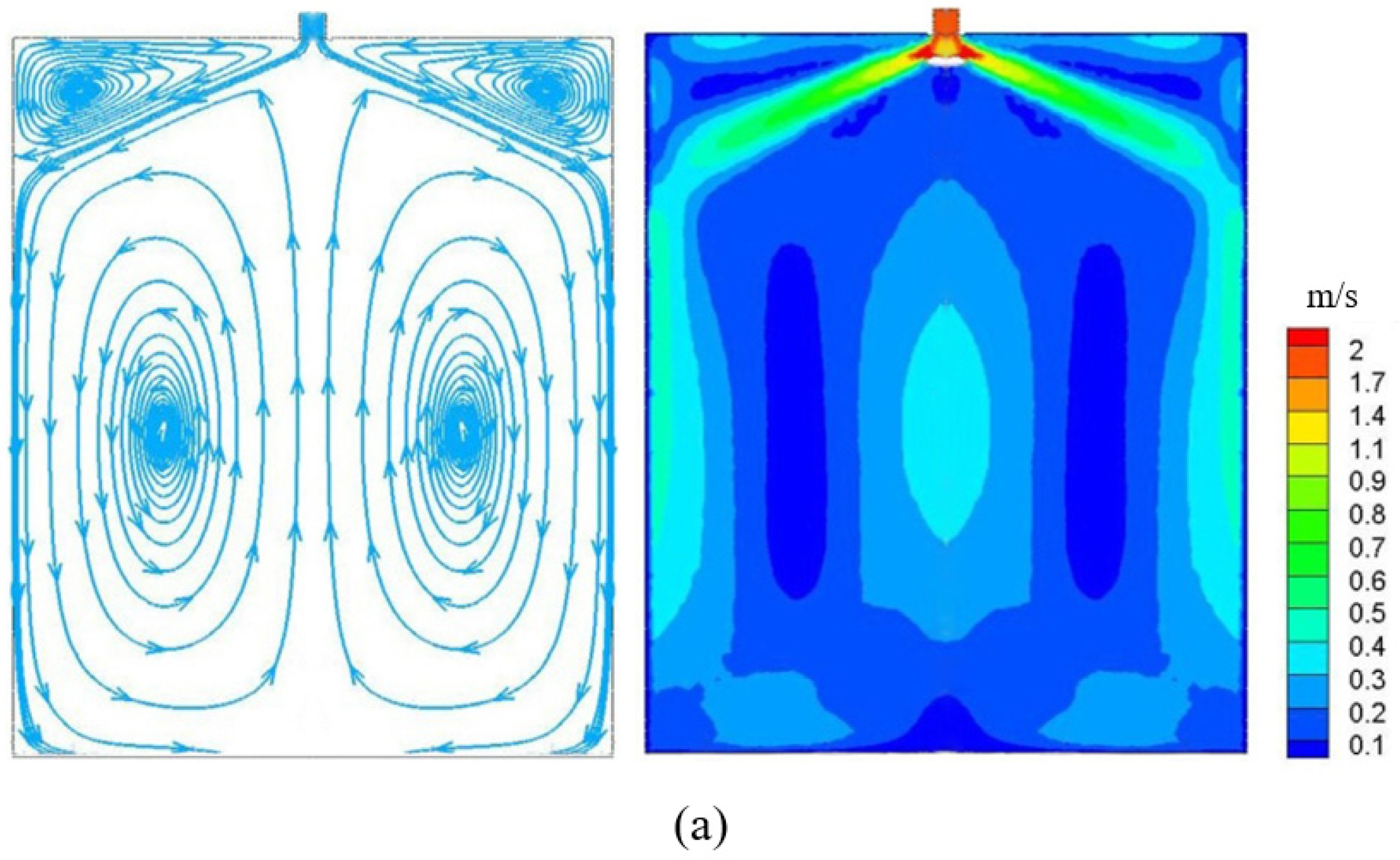
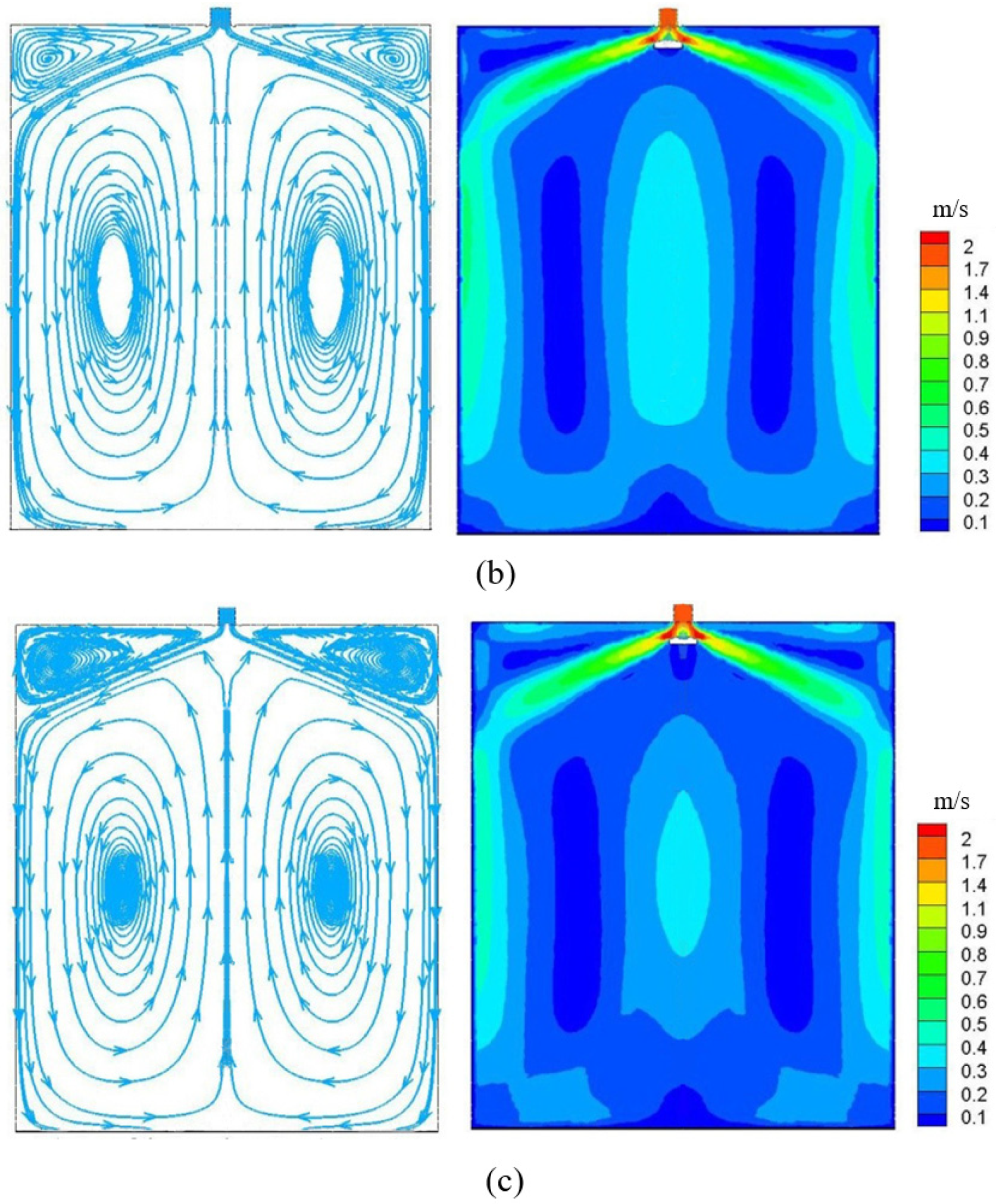
4.2. Nozzle Outlet Flow Field

A partial enlarged view of the velocity vector in the three nozzle regions is presented in Figure 3. It can be seen that the fluid steel passes through the nozzle at a high speed and flows out into the mold at a certain angle. In the mold, the strength of the slab is mainly guaranteed by the uniform solidified shell. If the local shell is too thin, the steel leakage accident will occur, and the consequences are very serious. If the impact force of the liquid steel ejected from the nozzle is too strong, the local shell will be too thin, which will affect the slab quality. When the A nozzle is used, the speed of the fluid steel flowing out of the nozzle is relatively large. In addition, the speed of the upper return zone generated by the rising stream is also relatively large when it moves to the vicinity of the nozzle. This leads to large fluctuations in the free liquid surface and easily produces slag, bubbles and other defects, while the turbulent area at the nozzle outlet is relatively small. When the nozzle of type B is used, the spherical area at the bottom of the nozzle reduces the flow rate of the fluid steel at the outlet of the nozzle. Moreover, the speed of the rising stream is significantly reduced, the fluctuation of the free liquid surface of the fluid steel is small and the liquid level is more stable. When the nozzle of type C is used, due to the large outlet area, the fluid steel flowing from the immersion nozzle and the upper return area, which moves upward after hitting the narrow surface, meet at the upper part of the nozzle outlet. This results in a turbulent flow, which adversely affects the mold. The inflow of the mold slag near the center of the wide face has adverse effects. In addition, the lower recirculation zone has a low velocity, and the fluid steel has a small momentum, which results in a turbulent flow at the bottom of the nozzle and interferes with the flow of the fluid steel in the adjacent area.

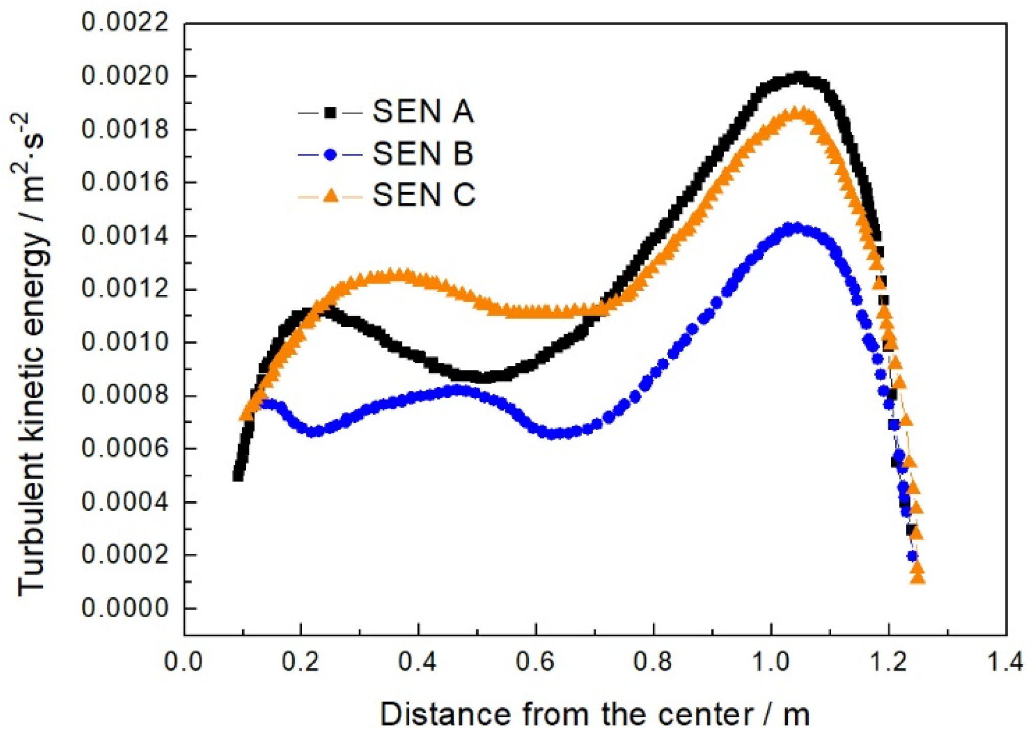
4.3. Free-Surface Turbulent Kinetic Energy

Figure 4 and Figure 5 show the turbulent kinetic energy and the velocity distribution of free surfaces with a different SEN. The surface of the molten steel is covered with protective slag in the mold; the molten slag will flow into the gap between the mold and the shell to improve the lubrication and heat transfer. High turbulent kinetic energy of the liquid level will affect the uniform flow of the slag, resulting in the uneven thickness of the solidified shell, and then affect the quality of the slab. It can be seen that the maximum values of the turbulent kinetic energy of the three nozzles all appear around 1000 mm from the center. In addition, when the fluid steel in the upper circulation area reaches the meniscus, the velocity component perpendicular to the liquid surface direction obtains a local extremum, and the horizontal velocity parallel to the liquid surface direction is also high, which results in a local extremum of the turbulent kinetic energy. The turbulent kinetic energy of the free liquid surface of nozzle A is the largest, reaching 0.00204 m2·s−2. The turbulent kinetic energy of nozzle C is slightly lower (0.00193 m2·s−2), and the free-liquid-surface turbulent kinetic energy of nozzle B (0.00154 m2·s−2) is the smallest. The distribution of the horizontal flow velocity of the free liquid surface of nozzles A and C are relatively close. In the area from the nozzle to the 1/4 section, because the vortex center of the lower recirculation zone of C is closer to the meniscus, the fluid steel flows faster back to the meniscus. Therefore, its turbulent kinetic energy is higher than that of nozzle A. The vortex center of the upper recirculation zone of nozzle B is closer to the narrow surface. The longer flow path aggravates the momentum loss of the fluid steel in the process of flowing back to the free surface. Therefore, the surface velocity of nozzle B is significantly lower than that of nozzles A and C, and the turbulent kinetic energy of the liquid surface is also lower.

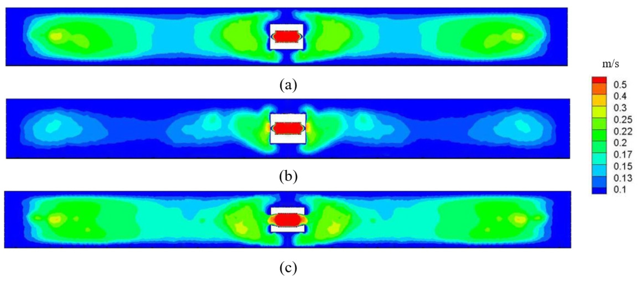
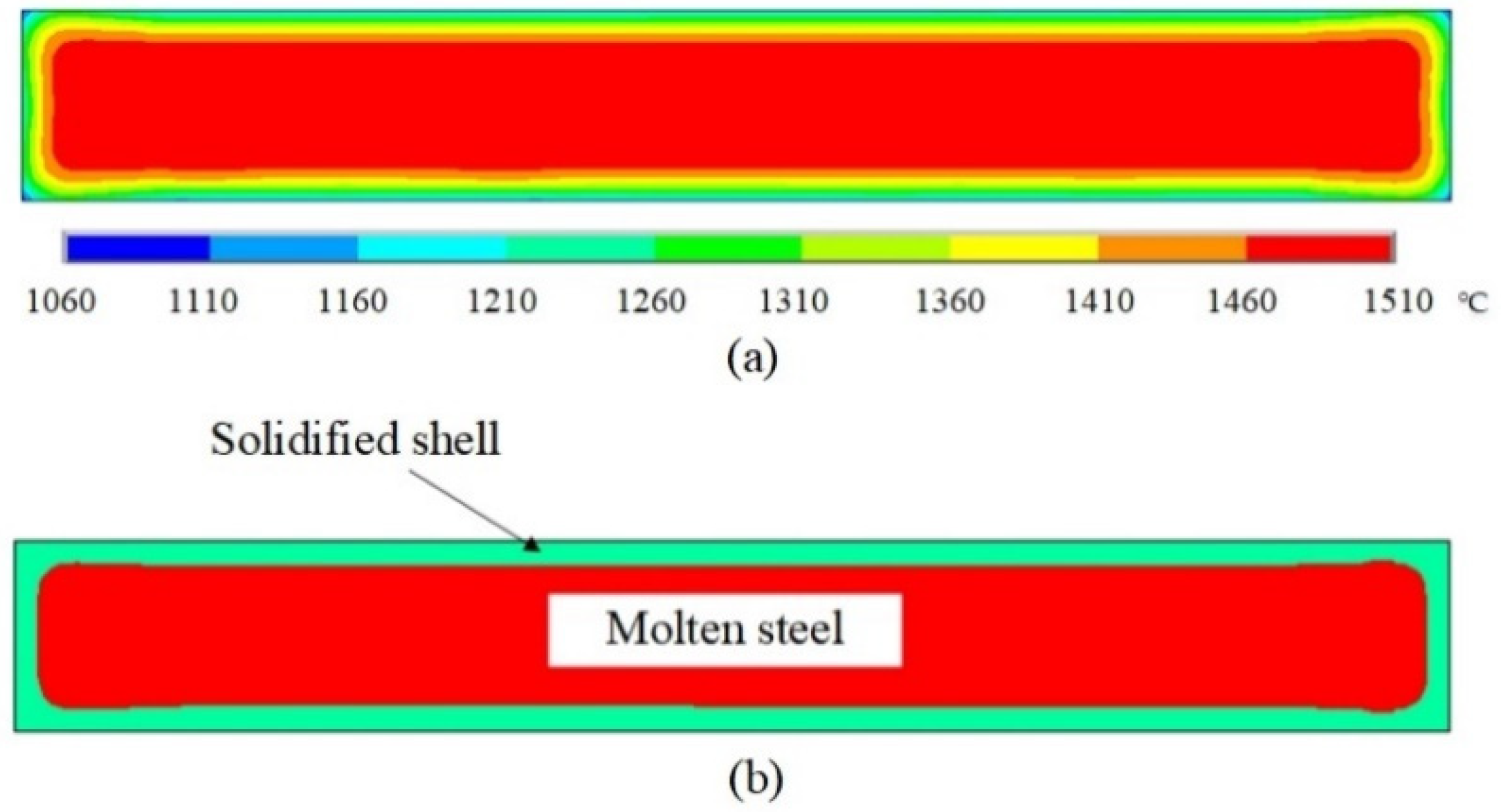
4.4. Heat Transfer and Solidification

In summary, the surface velocity and the turbulent kinetic energy of nozzle B are the lowest, which indicates that the SEN B is the best structure. The temperature field and solidification situation are further calculated by considering nozzle B as the example. Figure 6 presents the temperature distribution and solidified shell at the height of 500 mm below the meniscus. The temperature is 1510 °C in the center of the liquid steel and it is below the solidus temperature at the edge. There is a local high-temperature region at the off-corner region, denoted by the “hot spots”, which results in the local thin shell in the off-corner. The thickness of the shell at the wide face is a bit larger than that of the narrow face. In general, the thickness distribution of the solidified shell is uniform, which indicates that the heat transfer is uniform. The uniform shell thickness can ensure the strength of the slab, avoid a steel leakage accident and make the solidification structure uniform, which can improve the quality of the slab. It also shows that the fluid steel sprayed from nozzle B forms a stable flow field, so that the heat can be stably and uniformly transferred from the fluid steel to the mold. Therefore, the solidification of the billet shell is uniform, which is beneficial for improving the quality of the slab.

5. Conclusions

In this paper, three different structures of the SEN are assessed by calculating the fluid characteristic in the continuous casting machinery. The conclusions are summarized as follows:
  • The fluid steel flows out from the nozzle at a certain angle. When the main stream approaches the narrow surface, the flow rate and momentum of the fluid steel gradually decrease and two split streams are formed.
  • The spherical area at the bottom of the nozzle can reduce the flow rate of the fluid steel at the outlet of the nozzle. In addition, the speed of the rising stream is significantly reduced, the fluctuation of the free liquid surface of the fluid steel is small and the liquid level is more stable.
  • The turbulent kinetic energy of the free liquid surface of nozzles A, B and C are 0.00204, 0.00154 and 0.00193 m2·s−2, respectively, which shows that nozzle B is the best.
  • In the future work, more nozzle structures will be researched to compare the influence of the nozzle structure on the flow and solidification characteristics. In addition, more of the actual slab quality in a steel factory will be examined to reveal the corresponding relationship between the nozzle structure and slab quality.

Author Contributions

Data curation, T.L. and Y.Z.; methodology, K.Z.; writing—original draft, F.D. All authors have read and agreed to the published version of the manuscript.

Funding

This research received no external funding.

Institutional Review Board Statement

Not applicable.

Informed Consent Statement

Not applicable.

Data Availability Statement

Not applicable.

Conflicts of Interest

The authors declare no conflict of interest.

Nomenclature

SENSubmerged entry nozzle
vVelocity vector
ρDensity
tTime
pPressure
FExternal volume force
τStress tensor
IUnit tensor
cρSpecific heat capacity
TTemperature
kHeat transfer coefficient
STViscous dissipation term
TopThe top of the mold
BottomThe exit of the mold
Narrow faceThe narrow copper plate of the mold
Wide faceThe wide copper plate of the mold

References

  1. Rasheed, H.U.; Islam, S.; Zeeshan; Khan, J.; Abbas, T.; Mohmand, M.I. Numerical solution of chemically reactive and thermally radiative MHD Prandtl nanofluid over a curved surface with convective boundary conditions. ZAMM-J. Appl. Math. Mech. 2021, e202100125. [Google Scholar] [CrossRef]
  2. Thomas, B.G.; Zhang, L. Mathematical modeling of fluid flow in continuous casting. ISIJ Int. 2001, 10, 1181–1193. [Google Scholar] [CrossRef]
  3. Gupta, D.; Chakraborty, S.; Lahiri, A.K. Asymmetry and oscillation of the fluid flow pattern in a continuous casting mould: A water model study. ISIJ Int. 1997, 37, 654–658. [Google Scholar] [CrossRef]
  4. Korti, A.I.N.; Khadraoui, Y. A numerical simulation of the DC continuous casting using average heat capacity. Scand. J. Met. 2004, 33, 347. [Google Scholar] [CrossRef]
  5. Rasheed, H.U.; AL-Zubaidi, A.; Islam, S.; Saleem, S.; Khan, Z.; Khan, W. Effects of joule heating and viscous dissipation on magnetohydrodynamic boundary layer flow of jeffrey nanofluid over a vertically stretching cylinder. Coatings 2021, 11, 353. [Google Scholar] [CrossRef]
  6. Khan, Z.; Rasheed, H.U.; Khan, I.; Abu-Zinadah, H.; Aldahlan, M.A. Mathematical simulation of casson MHD flow through a permeable moving wedge with nonlinear chemical reaction and nonlinear thermal radiation. Materials 2022, 15, 747. [Google Scholar] [CrossRef]
  7. Zeeshan. Second law and entropy generation analysis of magnetized viscous fluid flow over a permeable expandable sheet with nonlinear thermal radiation: Brownian and thermophoresis effect. Adv. Mech. Eng. 2022, 14, 16878140221075295. [Google Scholar] [CrossRef]
  8. Thomas, B.G. Modeling of the continuous casting of steel—Past, present, and future. Metall. Mater. Trans. B 2002, 33, 795–812. [Google Scholar] [CrossRef]
  9. Du, F.; Chen, C.; Zhang, K. Fluid characteristics analysis of the lubricating oil film and the wear experiment investigation of the sliding bearing. Coatings 2022, 12, 67. [Google Scholar] [CrossRef]
  10. Takatani, K.; Tanizawa, Y.; Mizukami, H.; Nishimura, K. Mathematical model for transient fluid flow in a continuous casting mold. ISIJ Int. 2001, 41, 1252–1261. [Google Scholar] [CrossRef] [Green Version]
  11. Zeeshan; Rasheed, H.U.; Khan, W.; Khan, I.; Alshammari, N.; Hamadneh, N. Numerical computation of 3D Brownian motion of thin film nanofluid flow of convective heat transfer over a stretchable rotating surface. Sci. Rep. 2022, 12, 2708. [Google Scholar] [CrossRef] [PubMed]
  12. Zhang, W.; Gao, J.; Rohatgi, P.K.; Zhao, H.; Li, Y. Effect of the depth of the submerged entry nozzle in the mold on heat, flow and solution transport in double-stream-pouring continuous casting. J. Mater. Process. Technol. 2009, 209, 5536–5544. [Google Scholar] [CrossRef]
  13. Tsukaguchi, Y.; Nakamura, O.; Jnsson, P.R.; Yokoya, S.; Tanaka, T. Design of swirling flow submerged entry nozzles for optimal head consumption between tundish and mold. ISIJ Int. 2007, 47, 1436–1443. [Google Scholar] [CrossRef] [Green Version]
  14. Najera-Bastida, A.; Morales, R.D.; Garcia-Hernandez, S.; Torres-Alonso, E.; Espino-Zarate, A. Shell thinning phenomena affected by heat transfer, nozzle design and flux chemistry in billets moulds. ISIJ Int. 2010, 50, 830–838. [Google Scholar] [CrossRef] [Green Version]
  15. Torren, A.E.; Morales, R.D.; Garcia-Hernandez, S.; Najera-Bastida, A.; Sandoval-Ramos, A. Influence of straight nozzles on fluid flow in mold and billet quality. Metall. Mater. Trans. B 2008, 39, 840–852. [Google Scholar] [CrossRef] [Green Version]
  16. Rasheed, H.U.; Islam, S.; Khan, Z.; Khan, J.; Mashwani, W.K.; Abbas, T.; Shah, Q.Y. Computational analysis of hydromagnetic boundary layer stagnation point flow of nano liquid by a stretched heated surface with convective conditions and radiation effect. Adv. Mech. Eng. 2021, 13, 16878140211053142. [Google Scholar] [CrossRef]
  17. Zeeshan; Khan, I.; Amina; Alshammari, N.; Hamadneh, N. Double-layer coating using MHD flow of third-grade fluid with Hall current and heat source/sink. Open Phys. 2021, 19, 683–692. [Google Scholar] [CrossRef]
  18. Shamsi, M.; Ajmani, S.K. Three dimensional turbulent fluid flow and heat transfer mathematical model for the analysis of a continuous slab caster. ISIJ Int. 2007, 47, 433–442. [Google Scholar] [CrossRef] [Green Version]
  19. Tripathi, A.; Ajmani, S.K.; Chandra, S. Numerical investigation of bias flow in a slab caster mould. Can. Metall. Quart. 2021, 60, 203–214. [Google Scholar] [CrossRef]
  20. Gupta, D.; Lahiri, A.K. Water modeling study of the jet characteristics in a continuous-casting mold. Steel Res. Int. 1992, 63, 201–204. [Google Scholar] [CrossRef]
  21. Bai, H.; Thomas, B.G. Turbulent flow of liquid steel and argon bubbles in slide-gate tundish nozzles: Part II. Effect of operation conditions and nozzle design. Metall. Mater. Trans. B 2001, 32, 269–284. [Google Scholar] [CrossRef]
  22. Bao, Y.; Zhu, J.; Jiang, W.; Wang, C.; Xu, B. Water modeling research on slag-entrapment in the mould of thin slab continuous caster. J. Univ. Sci. Technol. Beijing 1999, 21, 530. [Google Scholar] [CrossRef]
  23. Zhang, X.-W.; Jin, X.-L.; Wang, Y.; Deng, K.; Ren, Z.-M. Comparison of standard k-ε model and RSM on three dimensional turbulent flow in the SEN of slab continuous caster controlled by slide gate. ISIJ Int. 2011, 51, 581–587. [Google Scholar] [CrossRef] [Green Version]
  24. Takatani, K. Effects of electromagnetic brake and meniscus electromagnetic stirrer on transient molten steel flow at meniscus in a continuous casting mold. ISIJ Int. 2003, 6, 915–922. [Google Scholar] [CrossRef]
  25. Li, B.; Tsukihashi, F. Effects of electromagnetic brake on vortex flows in thin slab continuous casting mold. ISIJ Int. 2006, 12, 1833–1838. [Google Scholar] [CrossRef] [Green Version]
  26. Wang, Y.F.; Zhang, L.F. Transient fluid flow phenomena during continuous casting: Part I—Casting start. ISIJ Int. 2010, 12, 1777–1782. [Google Scholar] [CrossRef] [Green Version]
  27. Lu, B.W.; Yuan, F.L.; Wang, H.L.; Bai, H. Water model experimental study on the behavior of fluid flow in slab caster mold. Res. Iron Steel 2015, 43, 24–27. [Google Scholar] [CrossRef]
Figure 1. Three structures of SEN. (a) is SEN A, (b) is SEN B, (c) is SEN C.
Coatings 12 00631 g001
Figure 2. The trajectory line (left) and flow field (right) of (a) SEN A, (b) SEN B and (c) SEN C.
Coatings 12 00631 g002aCoatings 12 00631 g002b
Figure 3. Local amplification of the velocity vector with different (a) SEN A, (b) SEN B and (c) SEN C.
Coatings 12 00631 g003
Figure 4. Turbulent kinetic energy at free surface.
Coatings 12 00631 g004
Figure 5. The velocity distribution of free surface with different (a) SEN A, (b) SEN B and (c) SEN C.
Coatings 12 00631 g005
Figure 6. Temperature distribution and solidified shell. (a) temperature distribution; (b) solidified shell.
Coatings 12 00631 g006
Table 1. Operational parameters and steel properties.
ItemValue
Mold height (mm)900
Nozzle immersion depth (mm)130
Casting speed (m·min−1)0.8
Density of steel (kg·m−3)7200
Viscosity of steel (kg·m−1·s−1)0.0055
Pour point (°C)1510
Liquidius temperature (°C)1490
Solidus temperature (°C)1420
Specific heat of steel (J∙kg−1∙°C−1)740
Latent heat (J∙kg−1)274,950
Table 2. Grid sensitivity analysis.
Number of GridMaximum Free-Surface Turbulent Kinetic EnergyDeviation
75,6840.00136-
195,6340.001790.00037
380,5230.002010.00022
456,9510.002040.00003
506,5870.002050.00001
Publisher’s Note: MDPI stays neutral with regard to jurisdictional claims in published maps and institutional affiliations.

