Article

The Effects of Nozzle Inclination, Area Ratio, and Side-Hole Aspect Ratio on the Flow Behavior in Mold

1
International Shipping Research Institute, GongQing Institute of Science and Technology, Jiujiang 332020, China
2
Offshore Oil Engineering Co., Ltd., Tianjin 300461, China
3
College of Marine Engineering, Dalian Maritime University, Dalian 116000, China
*
Author to whom correspondence should be addressed.
Coatings 2022, 12(6), 815; https://doi.org/10.3390/coatings12060815
Submission received: 16 May 2022 / Revised: 7 June 2022 / Accepted: 9 June 2022 / Published: 10 June 2022
(This article belongs to the Special Issue Liquid–Fluid Interfaces and Dynamics)

Abstract

:
During the steel continuous casting, the submerged entry nozzle (SEN) plays a crucial role in the fluid characteristic of fluid steel, which further affects the slab quality. In this paper, a nozzle model is developed to study the influences of nozzle inclination, nozzle area ratio, and side hole aspect ratio on the fluid characteristic of fluid steel. The results show that when the nozzle angle increased from 10° to 20°, the impact points of the narrow surface were 0.402 m, 0.476 m, and 0.554 m away from the meniscus, respectively. In addition, when the nozzle area ratio increased from 0.96 to 1.16, it resulted in a significant decrease of the speed of high-temperature liquid steel flowing out of the nozzle. Moreover, when the side-hole aspect ratio was 1.47, the maximum turbulent kinetic energy of the free surface reached 0.00141 m2 s−2. Furthermore, when the aspect ratio was 1.67 and 1.84, a slight difference existed, and the maximum turbulent kinetic energy was almost 0.00095 m2 s−2. The proposed model can provide theoretical basis and guidance for nozzle optimization.

1. Introduction

Continuous casting is an efficient casting method. In the mold, the molten steel only solidifies near the mold wall. The thickness of the solidified shell is about 20–30 mm, while the middle part of the slab is in a liquid state. Therefore, the impact of molten steel flow field in the mold may cause the local shell temperature to be too high, resulting in remelting of solidified shell. Because the local shell thickness may be too thin under high temperature, leading to uneven stress on the shell, it is easy to produce crack defects. In serious cases, the solidified shell will be broken, resulting a serious breakout accident, as shown in Figure 1.
The structure of nozzle directly affects the flow field distribution of molten steel flowing into the mold. Different nozzle angles will cause different backflows, and the position of liquid steel impacting the narrow surface of slab is also different, which will affect the solidification state of slab shell. The nozzle area ratio and side-hole area ratio will affect the velocity of molten steel at the nozzle and produce different momentum of molten steel; it will also affect the flow field distribution, solidification state, and then affect the slab quality. Because of this, it is meaningful to investigate the effects of nozzle inclination, area ratio, and side-hole aspect ratio structure on the flow behavior in mold [1,2,3,4,5,6,7,8].
Many researchers studied the flow field in the mold [9,10,11,12,13]. For instance, Wang et al. [14] carried out a 3D numerical model describing the flow of liquid steel in a mold in order to simulate the coupling flow field and temperature field of the molten steel. The impacts of the bottom structure of SEN on the flow field and temperature field of molten steel were analyzed and compared. Moreover, the flow field results were validated by the water model. Deng et al. [15] developed a full-scale funnel-shaped thin slab water model in order to investigate the fluid flow, meniscus fluctuation, and slag-entrapping behaviors when they were fed by five three-port submerged entry nozzles with different diameters. Quan et al. [16] computed an unsteady three-dimensional flow in the mold region of the liquid pool during continuous casting of steel slabs, using realistic geometries starting from the submerged inlet nozzle. Yang et al. [17] built a three-dimensional comprehensively coupled model in order to describe the transport phenomena, including fluid flow, heat transfer, solidification, and solute redistribution in the continuous casting process. Tripathi et al. [18] focused on the flow phenomenon and analyzed the causes leading to the bias flow using computational fluid dynamics simulations. The results showed a consistent bias flow at one side of the caster, even when the submerged entry nozzle and other flow parameters were perfectly aligned. Bai and Thomas [19] studied the influence of different nozzle outlet shapes on the angle of the outlet stream by combining a 3D finite-volume model and a water model. The results showed that the jet angle of the square outlet was higher than the nozzle design angle. In addition, the jet angle of the rectangular outlet was generally similar to the design angle, while the jet angle of the narrow and long outlet was lower than the design angle. Gupta et al. [20] studied the frequency of flow oscillation for different mold dimensions, the SEN position and its configuration, and fluid inlet condition into the mold. Thomas et al. [21] reviewed recent developments in modeling phenomena related to fluid flow in the continuous casting mold region, as well as the resulting implications for improving the process. Rasheed et al. [22] investigated an unsteady magnetohydrodynamic mixed convective and thermally radiative Jeffrey nanofluid flow in view of a vertical stretchable cylinder with radiation absorption and heat.
Although some studies have been performed on the flow field in the mold, there are still few reports on the influence of the structural details of the nozzle on the flow field distribution. The influences of nozzle inclination, nozzle area ratio, and side-hole aspect ratio on the distribution of liquid steel flow field is still unclear. The molten steel flows into the mold through the nozzle and then changes the flow field of molten steel. The flow field affects the solidification of slab, the melting of mold flux, and the thickness of slab shell. Therefore, the nozzle structure has an important impact on the quality of slab. Thus, this paper develops a three-dimensional nozzle model in which the nozzle inclination, nozzle area ratio, and side-hole aspect ratio can be changed. The proposed model can provide theoretical basis and guidance for nozzle optimization.

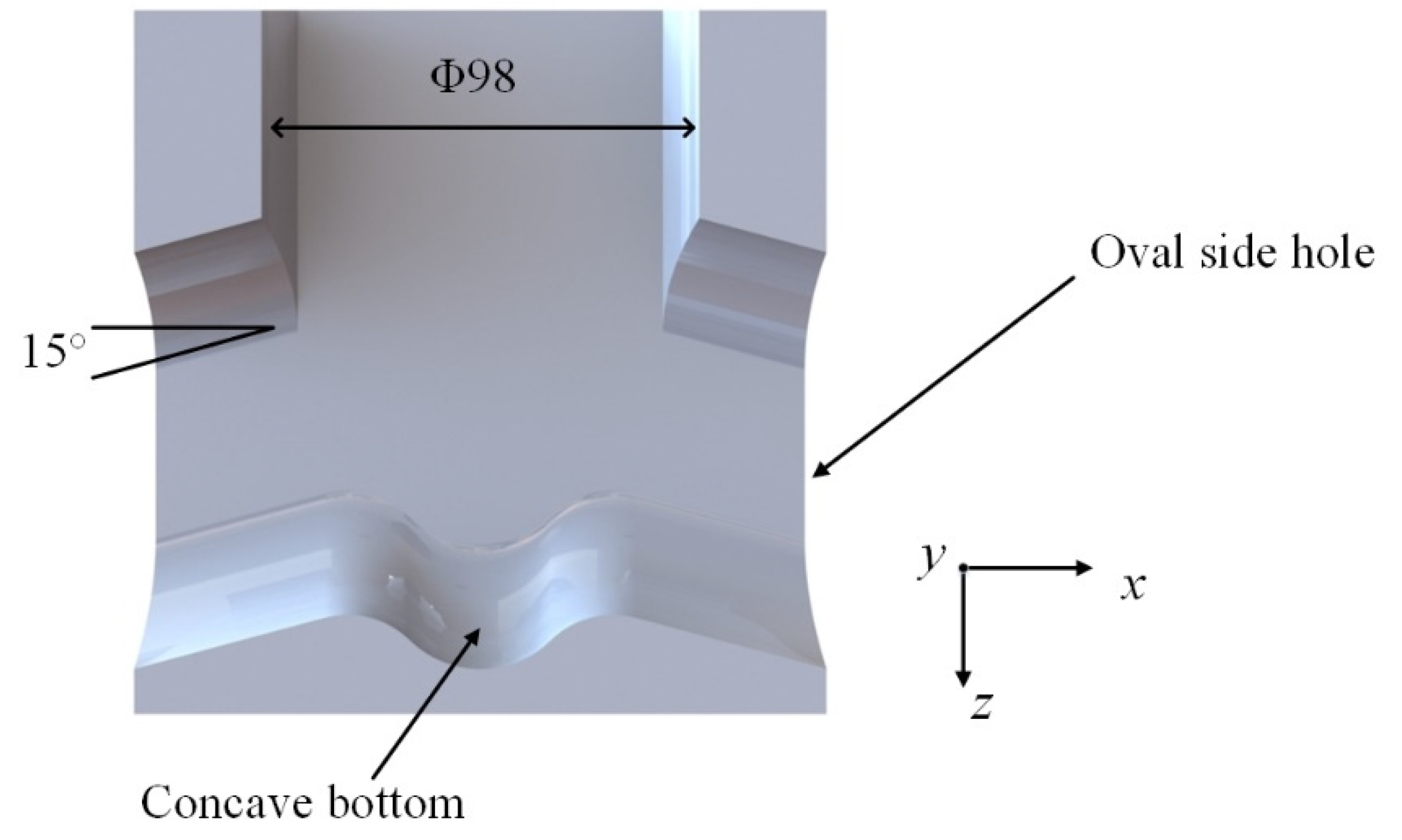
2. Description of Nozzle
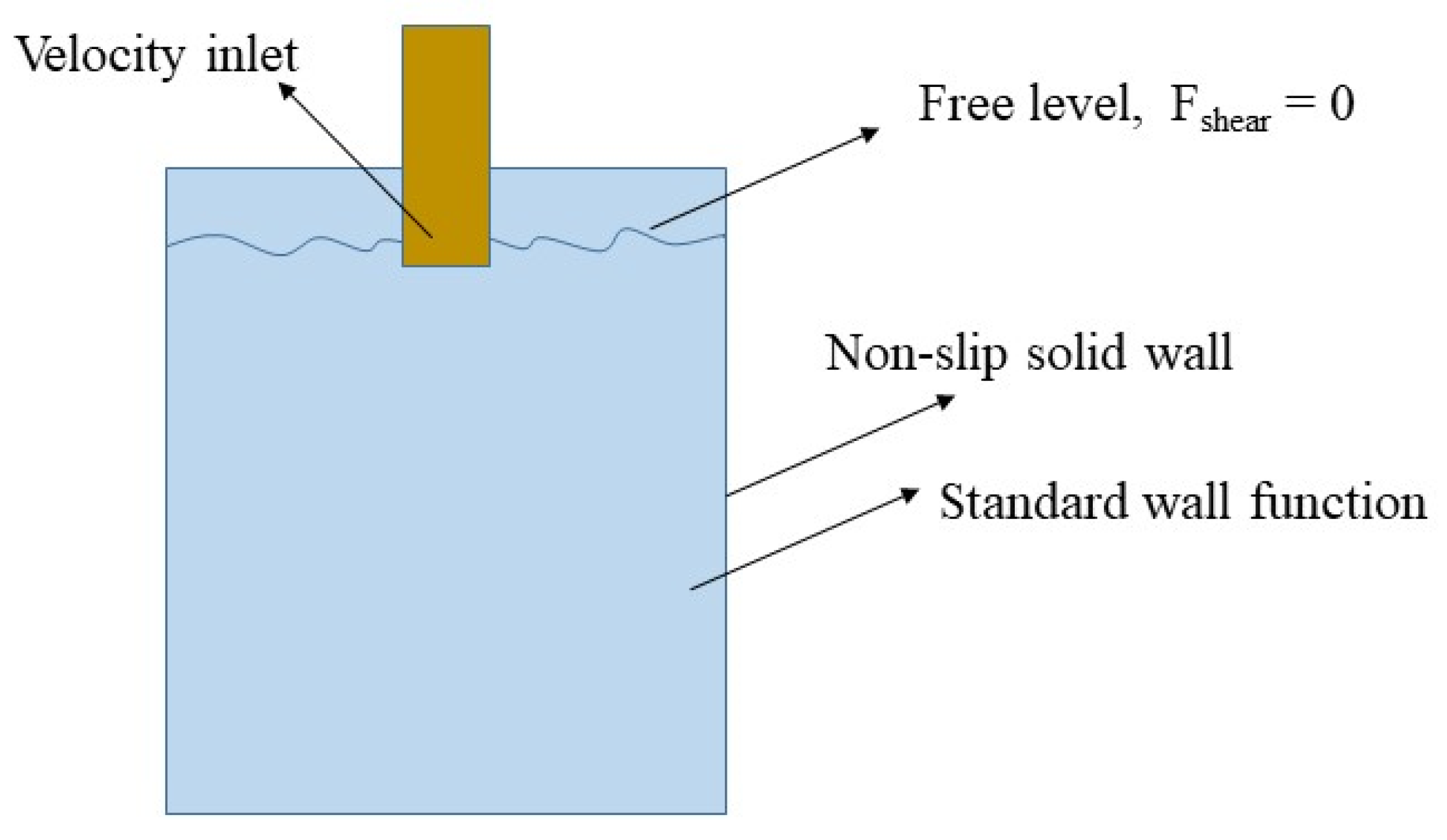
Figure 2 shows the structural diagram of the submerged nozzle. The nozzle is a concave bottom nozzle with a double-sided mouth structure, having an inner diameter of 98 mm and a downward inclination angle of 15°. The outlet shape is oval and has a size of 54 × 90 mm. The influence of different nozzle parameters on the liquid steel flow field can be explored by changing the nozzle inclination, nozzle area ratio, and side-hole aspect ratio.

3. Fluid Model

The fluid characteristic of steel was simulated using the Fluent software.
The considered assumptions are summarized as follows:
(1) The fluid steel flow was an incompressible steady flow.
(2) The influence of the mold vibration and mold slag on the flow was ignored.
(3) The natural convection caused by density changes was ignored.
(4) The influence of the heat transfer and slab condensate on the flow was ignored.
(5) The calculation boundary was a no-slip boundary.
The governing equations are given by [23]:
(1) Continuity equation:
ρ t + × ( ρ v ) = 0
where v is the velocity vector, ρ is the density, and t is the time.
(2) Momentum equation:
t ( ρ v ) + × ( ρ v v ) = p + × ( τ ) + F
τ = μ [ ( v + v T ) ] 2 3 × v I
where p is the pressure on the fluid cell, F is the external volume force, τ is the stress tensor, and I is the unit tensor.
(3) Energy conservation equation:
( ρ T ) t + div ( ρ v T ) = div ( k c ρ grad T ) + S T
where cρ is the specific heat capacity, T is the temperature, k is the heat transfer coefficient of the fluid, and ST is the viscous dissipation term.
(4) Standard k-ε equation:
( ρ v j k ) x j = x j ( μ τ σ k k x j ) + G k ρ ε
( ρ v j ε ) x j = x j ( μ τ σ k ε x j ) + C 1 G k s k C 2 ρ s 2 k
The boundary conditions are given by:
(1) The nozzle inlet was defined as the velocity inlet.
(2) The computational domain exit was defined as the speed exit, while the speed was equal to the casting speed.
(3) The mold liquid level was set as free liquid level, and the shear force was null.
(4) Both the mold wall and nozzle wall were treated as non-slip solid walls, while the flow field near the wall was treated as a standard wall function. The temperature boundary condition of the nozzle wall was treated as adiabatic. The mold wall was calculated using the second type of heat transfer boundary condition, and the heat flow was applied to the surface of the billet in the mold using a profile file, as shown in Figure 3.
The equations were solved using the commercial software FLUENT. The QUICK scheme was adopted for the convection term, and the SIMPLEC algorithm was used to treat the pressure terms in the momentum equations.
Table 1 shows the grid sensitivity. For this model, when the grid node was greater than 450,000, the deviation of maximum free-surface turbulent kinetic energy was very small. It can be regarded that the number of grids has no impact on the simulation results.
The calculated parameters are shown in Table 2.

4. Results and Discussion

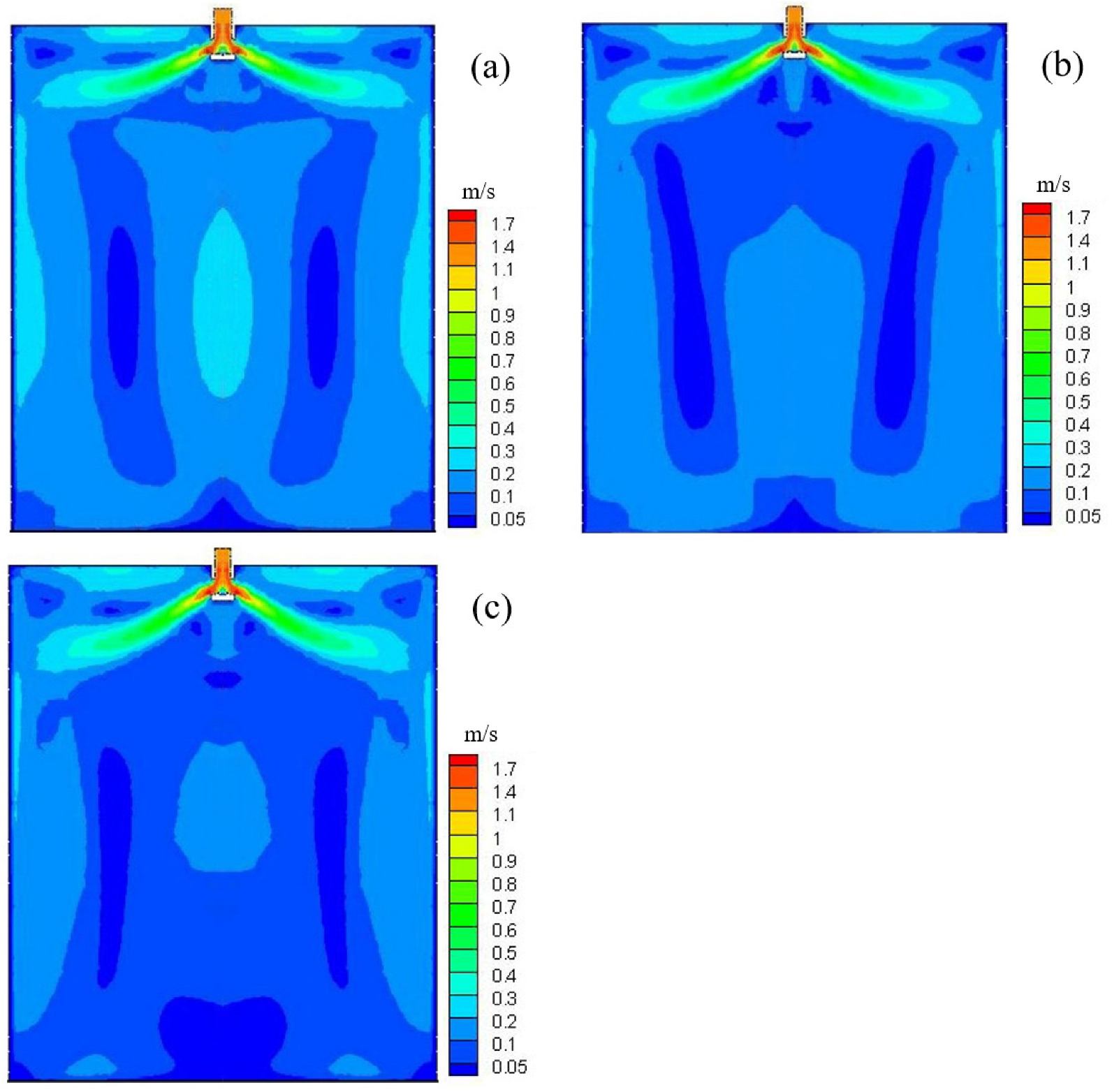
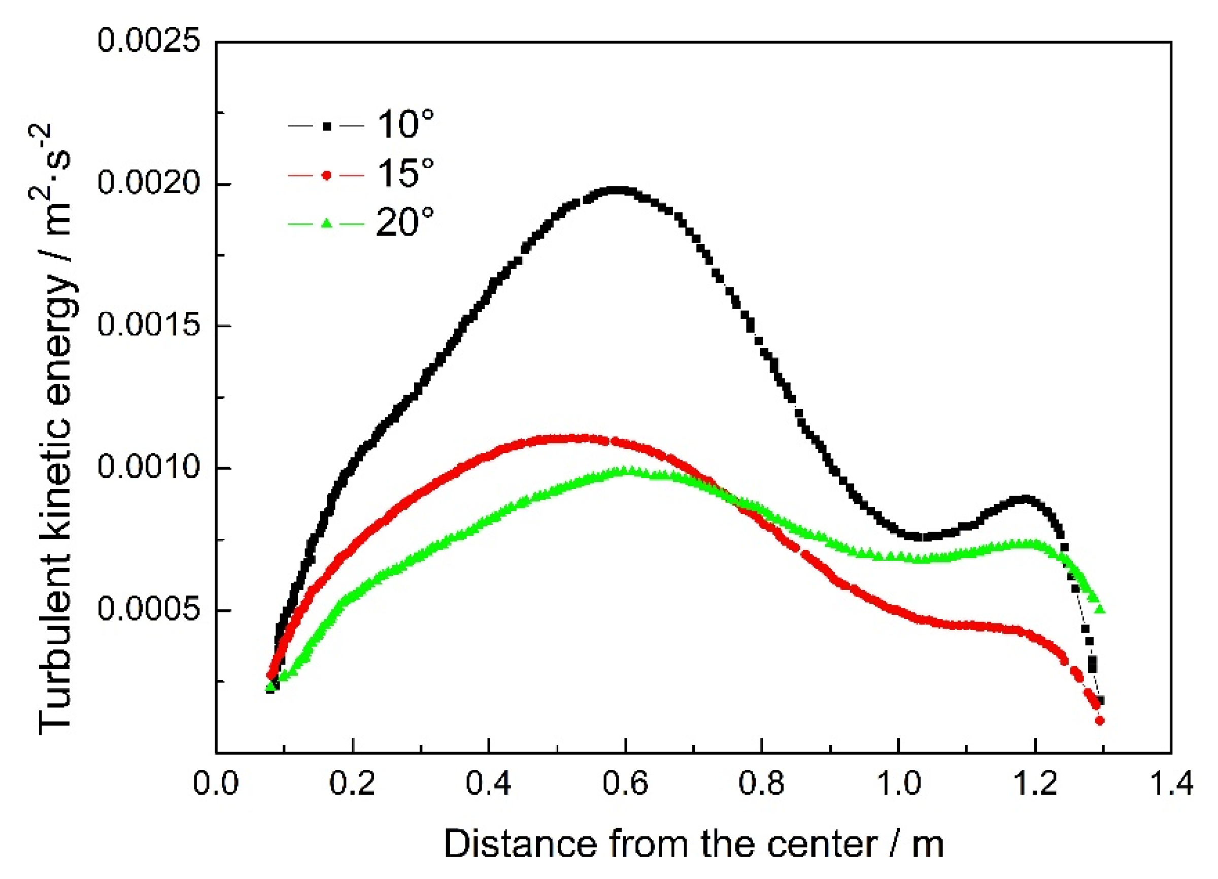
4.1. Flow Field Characteristics of Different Nozzle Angles

Figure 4 shows the flow field distribution in the mold for different nozzle side-hole angles (10°, 15°, and 20°). The spherical area at the bottom of the nozzle reduced the velocity of molten steel at the outlet of the nozzle, the velocity of the upwelling strand decreased significantly, the fluctuation of the free liquid level of molten steel was small, and the liquid level was relatively stable, which provided a more stable working condition for the melting and inflow of mold flux. It can be seen that when the nozzle angle increased from 10° to 20°, the flow slab direction at the outlet of the nozzle tilted downward, the distance between the upper reflux and the liquid surface increased, the kinetic energy loss of the flow slab returning to the meniscus increased, the flow velocity at the liquid surface decreased, the stability increased, and the disturbance weakened. This reduced the involvement of mold flux and provided a more stable working condition for the flow and melting of mold flux. However, the impact position of mainstream slab on the narrow surface of slab changed with the increase of the nozzle angle. When the nozzle angle increased from 10° to 20°, the impact points of the narrow surface were 0.402 m, 0.476 m, and 0.554 m away from the meniscus, respectively, and the change of impact position was very clear. The impact position was lowered by 0.074 m and 0.078 when the nozzle angle increased from 10° to 20°. If the impact position was too deep, the slab quality was reduced, which can easily lead to the secondary melting of the primary solidified shell and thinning, and a steel leakage accident will occur in serious cases. The results agree with the results simulated by Takatani and Li et al. [24,25].
Table 3 presents the vortex center positions of the upper and lower reflux zones formed by molten steel in the mold for different nozzle inclinations. When the inclination angle increased, the upper vortex center moved toward the mold outlet and narrow surface. When the inclination of the nozzle increased from 10° to 15°, the position of the lower vortex center moved significantly down. When the inclination increased to 20° due to the expansion of the lower reflux stream, the downward reflux speed of liquid steel was generally higher, and the position of the lower vortex center rose to 1.51 m away from the meniscus. The influence of nozzle inclination on the turbulent kinetic energy of free surface in the mold is shown in Figure 5. It can be seen that when the inclination angle was small, the turbulent kinetic energy of the free surface sharply changed, and the maximum turbulent kinetic energy reached 0.00195 m2 s−2. In addition, when the inclination angle was 15° and 20°, the change of turbulent kinetic energy of free surface was relatively gentle.

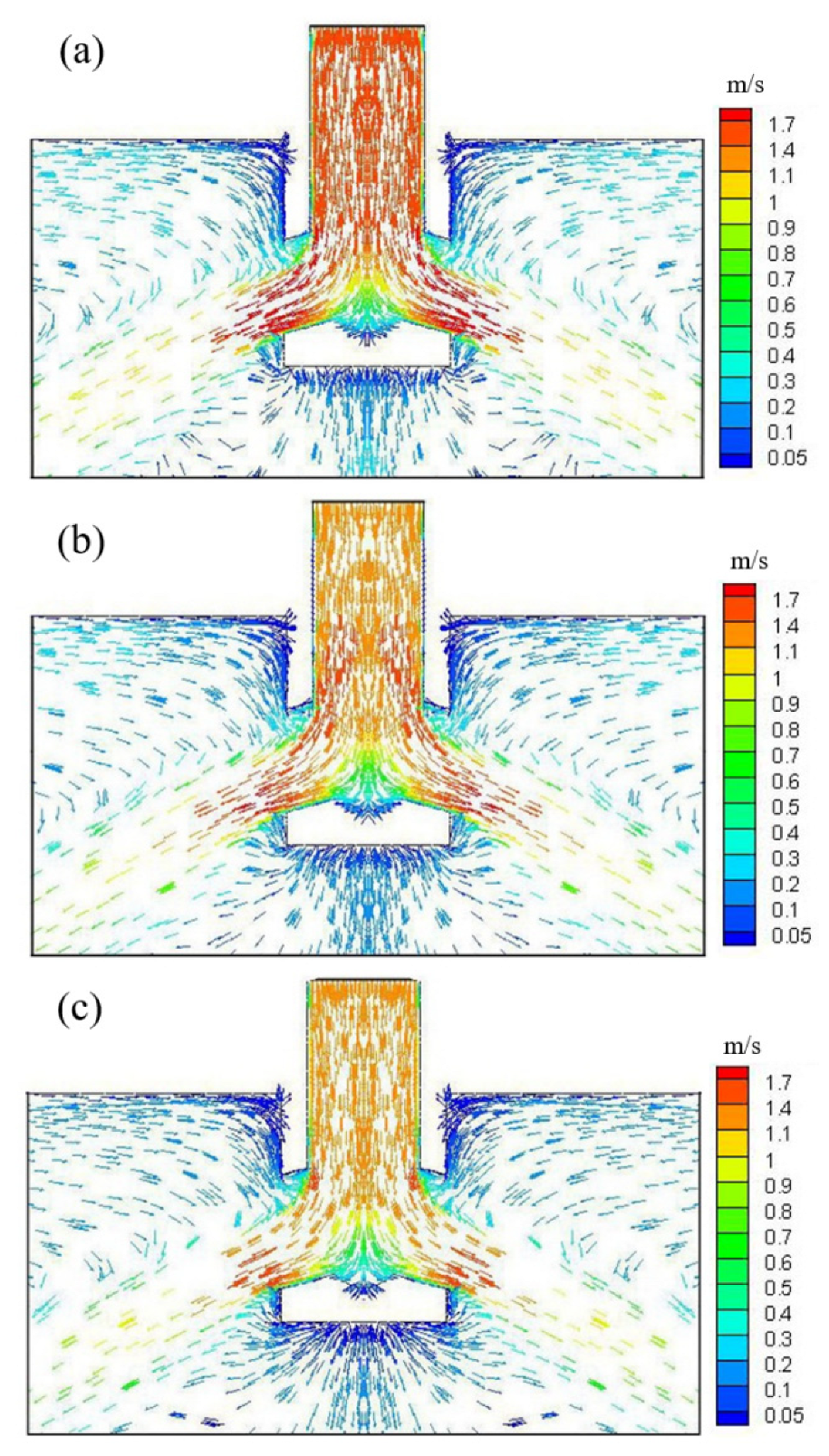
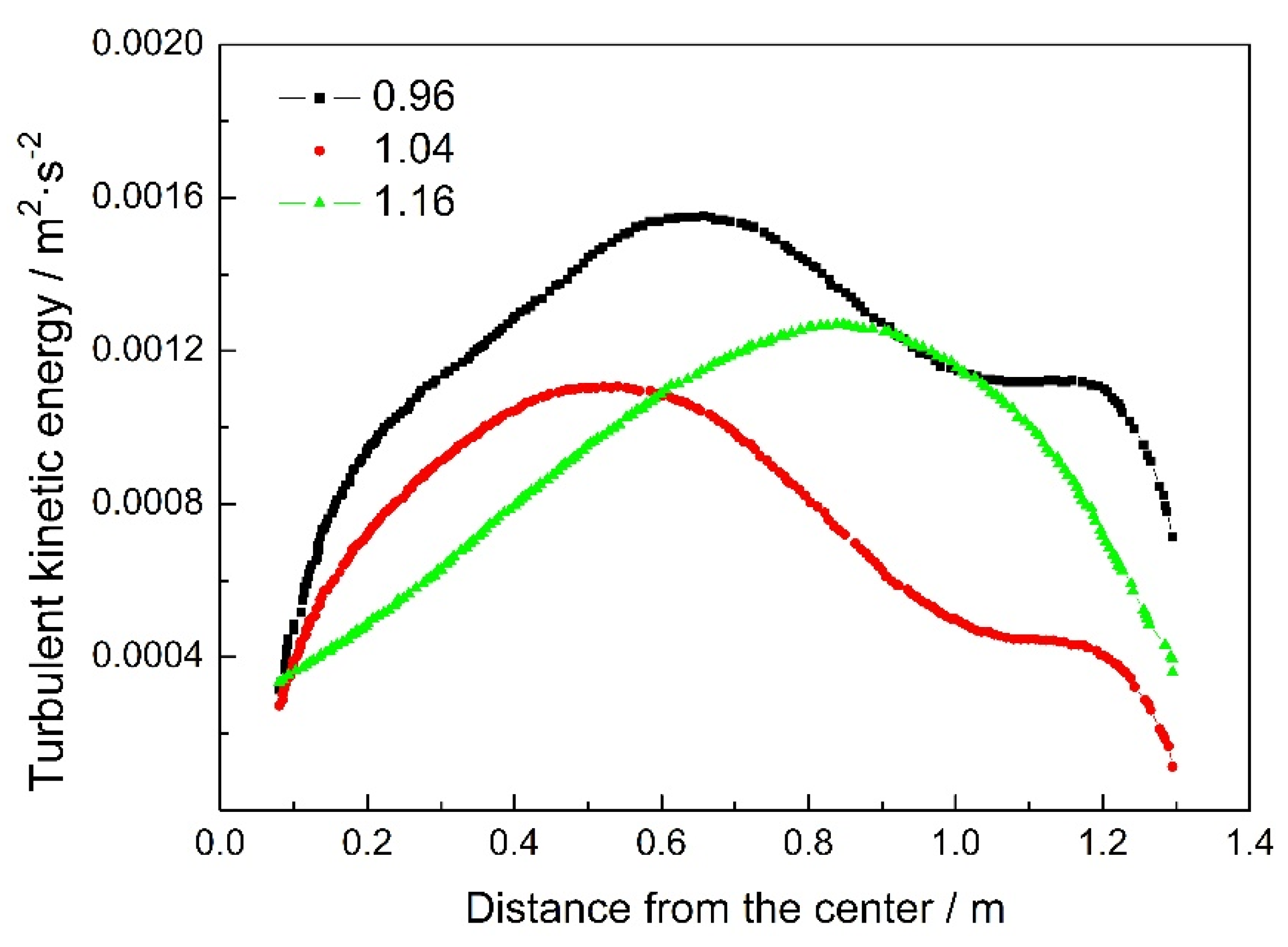
4.2. Flow Field Characteristics of Different Nozzle Area Ratios

The nozzle area ratio was defined as the ratio of the side-hole area of the submerged nozzle to the cross-sectional area of the nozzle. The area ratio of nozzle was considered as 0.96, 1.04, and 1.16, respectively. Figure 6 presents a locally enlarged vector diagram of the liquid steel flow field at the nozzle outlet. It can be seen that when the area ratio increased from 0.96 to 1.16, the inner diameter and side-hole area of the nozzle increased, which resulted in a significant decrease of the speed of high-temperature liquid steel flowing out of the nozzle. The speed of liquid steel was highest when the nozzle area ratio was 0.96, while it was lowest when the nozzle area ratio was 1.16. Because the molten steel flowed into the mold from the tundish, the flow velocity of the nozzle was determined by the casting speed, the inner diameter of the nozzle, and the outlet area. The area ratio of the nozzle will significantly affect the outflow speed of molten steel from the nozzle, which will lead to different backflow and impact positions. This is due to the fact that when the drawing speed is constant, the steel flow rate of the outlet is certain per unit time, and the increase of the outlet area reduces the flow rate of liquid steel to achieve equilibrium.
Table 4 shows the vortex center position and narrow impact position of the upper and lower reflux zones formed by molten steel in the mold, for different area ratios of submerged nozzle. For the vortex center in the upper recirculation zone, the area ratio moved downward from small to large, and the area ratio was significantly closer to the narrow surface than 1.16 and 1.04. This corresponded to the decreasing trend of the velocity of molten steel flowing into the mold. The smaller flow rate reduced the momentum of molten steel and weakened the upward reflux stream. The impact position of the narrow surface changed from 0.482 m away from the meniscus to 0.476 m and 0.468 m. The increase of the nozzle area ratio shortened the distance of the liquid steel reflux, which reduced the impact depth of liquid steel on the narrow surface.
The influence of different nozzle area ratios on the turbulent kinetic energy of free surface is shown in Figure 7. When the area ratio increased, the initial velocity of molten steel entering the mold decreased and had less momentum, and the turbulent kinetic energy of liquid surface decreased. When the area ratio was 1.16, the vortex center position of the upper reflux area was close to the narrow surface, which caused the upward reflux to clearly fluctuate near the narrow surface. This can easily lead to the involvement of protective slag and adversely affect the initial solidification behavior of the slab.

4.3. Flow Field Characteristics of Different Side-Hole Aspect Ratios

Figure 8 shows the local enlarged view of molten steel flow at the nozzle outlet, comparing the changes of mold flow field with side-hole aspect ratios of 1.47, 1.67, and 1.84. Table 5 presents the vortex center position and narrow surface impact position in the upper and lower recirculation areas of the flow field for different aspect ratios. The results show that when the aspect ratio increased, the vortex center and narrow surface impact position in the upper and lower recirculation zone first moved downward and then upward, and the variation range was mainly the same. The closer the vortex center of the upper reflux zone was to the free surface, the more energy could be brought to the melting of the mold flux, but this can easily lead to the violent fluctuation of the free liquid level and the involvement of the mold flux. The impact position of the narrow surface was too deep, which is not conducive to the floating of inclusions. However, it reduced the quality of slab and produced more casting defects.
The influence of different side-hole aspect ratios on the turbulent kinetic energy of free surface is shown in Figure 9. It can be seen that the liquid steel fullness at the outlet of the side hole increased and the flow rate decreased. When the aspect ratio was 1.47, the maximum turbulent kinetic energy of the free surface reached 0.00141 m2 s−2. In addition, when the aspect ratio was 1.67 and 1.84, a slight difference existed, and the maximum turbulent kinetic energy was almost 0.00095 m2 s−2. The maximum turbulent kinetic energy occurred near the nozzle at the position of 1/4 of the slab.

4.4. Heat Transfer and Solidification

A nozzle with an inclination angle of 15°, a side-hole ratio of 1.67, and a nozzle area ratio of 1.04 was chosen to research the temperature field and solidification. Figure 10 presents the solidification at different heights below the meniscus. The shell became thicker as the slab moved down. There was a local high-temperature region at the off-corner region, denoted by the “hot spots”, which resulted in the local thin shell in the off-corner. The thickness of the shell at wide face was a bit larger than that of the narrow face. The thickness of shell with narrow and wide sides was uniform, which reduced the occurrence of crack or breakout, so as to ensure the quality of slab.

5. Conclusions

A nozzle model was developed to investigate the influences of nozzle inclination, nozzle area ratio, and side-hole aspect ratio on the fluid characteristic of fluid steel. Through this model, the influence of different nozzle structures on the flow field of molten steel in the mold was mastered, and the impact position of a narrow surface, reflux area, and turbulent kinetic energy of liquid surface was defined, which provided a theoretical basis for improving the quality of a slab.
(1)
When the nozzle angle increased from 10° to 20°, the impact points of the narrow surface were 0.402 m, 0.476 m, and 0.554 m away from the meniscus, respectively.
(2)
When the area ratio increased from 0.96 to 1.16, the inner diameter and side-hole area of the nozzle increased, which resulted in a significant decrease of the speed of high-temperature liquid steel flowing out of the nozzle.
(3)
When the aspect ratio increased from 1.47 to 1.84, the vortex center and narrow surface impact position in the upper and lower recirculation zones first moved downward and then upward, and the variation range was mainly the same. When the aspect ratio was 1.47, the maximum turbulent kinetic energy of the free surface reached 0.00141 m2 s−2. Finally, when the aspect ratio was 1.67 and 1.84, a slight difference existed, and the maximum turbulent kinetic energy was almost 0.00095 m2 s−2.

Author Contributions

Data curation, T.L.; methodology, G.Z.; writing—original draft, F.D. All authors have read and agreed to the published version of the manuscript.

Funding

This research received no external funding.

Institutional Review Board Statement

Not applicable.

Informed Consent Statement

Not applicable.

Data Availability Statement

Not applicable.

Conflicts of Interest

The authors declare no conflict of interest.

Nomenclature

SENSubmerged entry nozzle
vVelocity vector
ρDensity
tTime
pPressure
FExternal volume force
τStress tensor
IUnit tensor
cρSpecific heat capacity
TTemperature
kHeat transfer coefficient
STViscous dissipation term

References

  1. Khan, Z.; Rasheed, H.U.; Khan, I.; Abu-Zinadah, H.; Aldahlan, M.A. Mathematical simulation of casson MHD flow through a permeable moving wedge with nonlinear chemical reaction and nonlinear thermal radiation. Materials 2022, 15, 747. [Google Scholar] [CrossRef] [PubMed]
  2. Zeeshan. Second law and entropy generation analysis of magnetized viscous fluid flow over a permeable expandable sheet with nonlinear thermal radiation: Brownian and thermophoresis effect. Adv. Mech. Eng. 2022, 14, 1–9. [Google Scholar] [CrossRef]
  3. Thomas, B.G. Modeling of the continuous casting of steel—Past, present, and future. Metall. Mater. Trans. B 2002, 33, 795–812. [Google Scholar] [CrossRef]
  4. Du, F.M.; Chen, C.D.; Zhang, K.G. Fluid characteristics analysis of the lubricating oil film and the wear experiment investigation of the sliding bearing. Coatings 2022, 12, 67. [Google Scholar] [CrossRef]
  5. Takatani, K.; Tanizawa, Y.; Mizukami, H.; Nishimura, K. Mathematical model for transient fluid flow in a continuous casting mold. ISIJ Int. 2001, 41, 1252–1261. [Google Scholar] [CrossRef]
  6. Han, S.W.; Cho, H.J.; Jin, S.Y.; Seden, M.; Lee, I.B.; Sohn, I. Effects of simultaneous static and traveling magnetic fields on the molten steel flow in a continuous casting mold. Metall. Mater. Trans. B 2018, 49, 2757–2769. [Google Scholar] [CrossRef]
  7. Morales, R.D.; Guarneros, J.; Chattopadhyay, K.; Najera-Bastida, A.; Rodriguez, J. Fluid flow control in a billet tundish during steel filling operations. Metals 2019, 9, 394. [Google Scholar] [CrossRef]
  8. Siddiqui, M.I.H.; Kim, M.H. Two-phase numerical modeling of grade intermixing in a steelmaking tundish. Metals 2019, 9, 40. [Google Scholar] [CrossRef]
  9. Zeeshan; Rasheed, H.U.; Khan, W.; Khan, I.; Alshammari, N.; Hamadneh, N. Numerical computation of 3D Brownian motion of thin film nanofluid flow of convective heat transfer over a stretchable rotating surface. Sci. Rep. 2022, 12, 2708. [Google Scholar] [CrossRef]
  10. Zhang, W.; Gao, J.; Rohatgi, P.K.; Zhao, H.; Li, Y. Effect of the depth of the submerged entry nozzle in the mold on heat, flow and solution transport in double-stream-pouring continuous casting. J. Mater. Process. Technol. 2009, 209, 5536–5544. [Google Scholar] [CrossRef]
  11. Tsukaguchi, Y.; Nakamura, O.; Jnsson, P.R.; Yokoya, S.; Tanaka, T. Design of swirling flow submerged entry nozzles for optimal head consumption between tundish and mold. ISIJ Int. 2007, 47, 1436–1443. [Google Scholar] [CrossRef]
  12. Najera-Bastida, A.; Morales, R.D.; Garcia-Hernandez, S.; Torres-Alonso, E.; Espino-Zarate, A. Shell thinning phenomena affected by heat transfer, nozzle design and flux chemistry in billets moulds. ISIJ Int. 2010, 50, 830–838. [Google Scholar] [CrossRef]
  13. Torren, A.E.; Morales, R.D.; Garcia-Hernandez, S.; Najera-Bastida, A.; Sandoval-Ramos, A. Influence of straight nozzles on fluid flow in mold and billet quality. Metall. Mater. Trans. B 2008, 39, 840–852. [Google Scholar] [CrossRef]
  14. Wang, C.N.; Wen, L.Y.; Chen, D.F.; Zhang, D.J.; Jin, X. Effect of bottom structure of submerged entry nozzle on flow field and temperature field in continuous casting mold. Iron Steel 2010, 45, 37–42. [Google Scholar] [CrossRef]
  15. Deng, X.X.; Wang, Q.Q.; Qian, L.; Wang, X.H.; Huang, F.X. Water model optimization of three-port submerged entry nozzle feeding a funnel-shaped thin slab mold. Iron Steel 2012, 47, 26–32. [Google Scholar] [CrossRef]
  16. Quan, Y.; Thomas, B.G.; Vanka, S.P. Study of transient flow and particle transport in continuous steel caster molds: PartⅠ. Fluid flow. Metall. Mater. Trans. B 2004, 35, 685–702. [Google Scholar] [CrossRef]
  17. Yang, H.L.; Zhang, X.Z.; Deng, K.; Li, W.; Zhao, L. Mathematical simulation on coupled flow, heat, and solute transport in slab continuous casting process. Metall. Mater. Trans. B 1998, 29, 1345–1356. [Google Scholar] [CrossRef]
  18. Tripathi, A.; Ajmani, S.K.; Chandra, S. Numerical investigation of bias flow in a slab caster mould. Can. Metall. Q. 2021, 60, 203–214. [Google Scholar] [CrossRef]
  19. Bai, H.; Thomas, B.G. Turbulent flow of liquid steel and argon bubbles in slide-gate tundish nozzles: Part II. Effect of operation conditions and nozzle design. Metall. Mater. Trans. B 2001, 32, 269–284. [Google Scholar] [CrossRef]
  20. Gupta, D.; Chakraborty, S.; Lahiri, A.K. Asymmetry and oscillation of the fluid flow pattern in a continuous casting mould: A water model study. ISIJ Int. 1997, 37, 654–658. [Google Scholar] [CrossRef]
  21. Thomas, B.G.; Zhang, L. Mathematical modeling of fluid flow in continuous casting. ISIJ Int. 2001, 10, 1181–1193. [Google Scholar] [CrossRef]
  22. Rasheed, H.U.; AL-Zubaidi, A.; Islam, S.; Saleem, S.; Khan, Z.; Khan, W. Effects of joule heating and viscous dissipation on magnetohydrodynamic boundary layer flow of jeffrey nanofluid over a vertically stretching cylinder. Coatings 2021, 11, 353. [Google Scholar] [CrossRef]
  23. Zhang, X.W.; Jin, X.L.; Wang, Y.; Deng, K.; Ren, Z.M. Comparison of standard k-ε model and RSM on three dimensional turbulent flow in the SEN of slab continuous caster controlled by slide gate. ISIJ Int. 2011, 51, 581–587. [Google Scholar] [CrossRef]
  24. Takatani, K. Effects of electromagnetic brake and meniscus electromagnetic stirrer on transient molten steel flow at meniscus in a continuous casting mold. ISIJ Int. 2003, 6, 915–922. [Google Scholar] [CrossRef]
  25. Li, B.K.; Tsukihashi, F. Effects of electromagnetic brake on vortex flows in thin slab continuous casting mold. ISIJ Int. 2006, 12, 1833–1838. [Google Scholar] [CrossRef]
Figure 1. Schematic diagram of fluid field in mold.
Coatings 12 00815 g001
Figure 2. The structures of SEN.
Coatings 12 00815 g002
Figure 3. Schematic diagram of boundary condition.
Coatings 12 00815 g003
Figure 4. Flow contours of molten steel in mold. (a) SEN angle of 10°. (b) SEN angle of 15°. (c) SEN angle of 20°.
Coatings 12 00815 g004
Figure 5. Influence of the SEN angle on the turbulent kinetic energy at free surface.
Coatings 12 00815 g005
Figure 6. Locally amplified figure of the velocity vector with different SEN. (a) Area ratio of 0.96. (b) Area ratio of 1.04. (c) Area ratio of 1.16.
Coatings 12 00815 g006
Figure 7. Influence of the area ratios of the turbulent kinetic energy at free surface.
Coatings 12 00815 g007
Figure 8. Locally amplified figure of the velocity vector with different SEN. (a) Aspect ratio of 1.47. (b) Aspect ratio of 1.67. (c) Aspect ratio of 1.84.
Coatings 12 00815 g008aCoatings 12 00815 g008b
Figure 9. Influence of the side-hole aspect ratio on the turbulent kinetic energy at free surface.
Coatings 12 00815 g009
Figure 10. Solidification of the shell at different heights. (a) 300 mm below the meniscus, (b) 500 mm below the meniscus.
Coatings 12 00815 g010
Table 1. Grid sensitivity analysis.
Number of GridMaximum Free-Surface Turbulent Kinetic EnergyDeviation
75,6840.00136-
195,6340.001790.00037
380,5230.002010.00022
456,9510.002040.00003
506,5870.002050.00001
Table 2. Calculated parameters.
ItemValue
Mold length 900 mm
Depth of level100 mm
Immersion depth of nozzle130 mm
Casting speed0.8 m·min−1
Steel density
Steel viscosity
7200 kg·m−3
0.0055 kg·m−1·s−1
Table 3. Upper and lower flow vortex core position.
Nozzle Inclination Upper Vortex Center Lower Vortex Center
10°(0.579 m,−0.195 m)(0.599 m,−1.650 m)
15°(0.590 m,−0.247 m)(0.613 m,−1.860 m)
20°(0.661 m,−0.261 m)(0.642 m,−1.510 m)
Table 4. Upper and lower flow vortex core position and narrow surface impact position.
Nozzle Area Ratio Upper Vortex Center Lower Vortex Center Impact Points of the Narrow Surface
0.96(0.665 m,−0.229 m)(0.628 m,−1.445 m)−0.482 m
1.04(0.590 m,−0.247 m)(0.613 m,−1.860 m)−0.476 m
1.16(0.746 m,−0.244 m)(0.622 m,−1.379 m)−0.468 m
Table 5. Upper and lower flow vortex core position and narrow surface impact position.
Side-Hole Aspect Ratio Upper Vortex Center Lower Vortex Center Impact Points of the Narrow Surface
1.47(0.637 m,−0.206 m)(0.607 m,−1.539 m)−0.358 m
1.67(0.590 m,−0.247 m)(0.613 m,−1.860 m)−0.476 m
1.84(0.607 m,−0.228 m)(0.559 m,−1.701 m)−0.398 m
Publisher’s Note: MDPI stays neutral with regard to jurisdictional claims in published maps and institutional affiliations.

