Article

In Situ High-Temperature Tensile Fracture Mechanism of PS-PVD EBCs

1
Chengdu Holy (Group) Industry Co., Ltd., Chengdu 610041, China
2
National Engineering Laboratory for Modern Materials Surface Engineering Technology, The Key Lab of Guangdong for Modern Surface Engineering Technology, Institute of New Materials, Guangdong Academy of Science, Guangzhou 510650, China
3
Guangxi Key Laboratory of Automobile Components and Vehicle Technology, Guangxi University of Science and Technology, Liuzhou 545006, China
*
Authors to whom correspondence should be addressed.
These authors contributed equally to this work.
Coatings 2022, 12(5), 655; https://doi.org/10.3390/coatings12050655
Submission received: 16 March 2022 / Revised: 18 April 2022 / Accepted: 19 April 2022 / Published: 11 May 2022
(This article belongs to the Special Issue Defects, Stresses and Cracks in Thermal Barrier Coatings)

Abstract

:
Environmental barrier coatings (EBCs) are increasingly being used in the high-temperature sections of gas turbines because of their protective effects on SiC fiber-reinforced SiC ceramic matrix composites (SiCf/SiC CMCs) when subjected to high-temperature water oxygen corrosion. The objective of this study was to investigate the failure behavior of EBCs prepared on SiCf/SiC CMC matrix materials under coupled high-temperature and load conditions. A plasma spray-physical vapor deposition (PS-PVD) method was used to prepare Si/3Al2O3·2SiO2/Yb2SiO5 EBC composite coatings on the surface of SiCf/SiC ceramic matrix composites. In situ scanning electron microscopy was used to study the evolutionary behavior of the coating surface cracks at different temperatures and the failure and fracture mechanism of the coating/substrate when held at 766 °C and subjected to different loading conditions. The results show that no significant crack extension occurred on the coating surface as the temperature of the coated specimen increased from room temperature to 766 °C in the absence of an applied tensile load, indicating that the effect of a single temperature factor on the failure of the specimen was negligible. However, under coupled high-temperature and load conditions, the specimens fractured at a load of 340 N when subjected to 766 °C, indicating that the coated sample is more likely to fail when subjected to high-temperature and tensile loading. The step-like fracture exhibits features consistent with the coating fracture and spalling caused by surface cracks extending from the coating surface to the interior. The spalling, large crack formation and step-like shape of the fracture in the coating and the substrate indicate that cracks were generated between the coating and the substrate under the coupled high-temperature and load conditions. The generation and extension of cracks in both parts eventually led to full specimen rupture.

1. Introduction

With the rapid development of aeroengines and turbine engines in the fields of aviation, aerospace, military and civil technology, the thermal loads and mechanical loads sustained by the hot-end components of such engines have further increased. To ensure their smooth operation and maintain a certain thermal efficiency, such components must possess excellent performance in terms of high temperature resistance. The temperature bearing capacity and the service lifetime of hot-end components can be improved using environmental barrier coating technology [1,2]. Environmental barrier coatings (EBCs) have good high-temperature corrosion resistance and are generally composed of complex multilayer structures, including bonded metal layers and ceramic layers [3]. Such coatings are resistant to high temperature, oxidation, corrosion and erosion, so they are widely used in many fields [4].
The traditional preparation methods of environmental barrier coatings include atmospheric plasma spray (APS) and electron beam-physical vapor deposition (EB-PVD) [5,6,7]. APS is used in the process of environmental barrier coating preparation because of its high-temperature plasma jet flame core (with temperatures as high as 10,000 °C) [8], which can make the particles on the substrate transform into a molten state during deposition, thus promoting mechanical combination and providing the coating with good high-temperature corrosion resistance and high deposition efficiency, although easily subject to thermal stress and circular failure [9]. The coatings prepared by EB-PVD exhibit a columnar structure, which is favorable for heat transfer and enhances the thermal cycling lifetime of the component. The coating material atoms, which are initially in the solid phase, are vaporized by electron beam heating and are then deposited as vapor-phase atoms. However, the deposition efficiency of the coating prepared by EB-PVD is low [10]. Plasma spray-physical vapor deposition (PS-PVD) is a thermal barrier coating preparation technology that emerged in the early 21st century and has advantages over APS [11,12]. A coating with a special structure can be prepared by PS-PVD, which offers the advantages of high deposition efficiency; and the fact that the resulting coatings exhibit considerably high porosity, low thermal conductivity, high strain tolerance and good hot corrosion resistance [13].
Silicon carbide fiber-reinforced SiC ceramic matrix composites (SiCf/SiC CMCs) have the advantages of low density, high strength, oxidation resistance, corrosion resistance and erosion resistance, and accordingly, are considered ideal materials for the front-end components of next-generation gas turbine engines [14,15,16,17,18]. However, SiCf/SiC CMCs suffer degraded performance with the risk of rapid oxidation, corrosion and shedding in high-temperature and high-press combustion environments [19,20]. To prevent the premature failure of SiCf/SiC CMCs in the combustion environment, an environmental barrier coating (EBC) was considered an ideal material for ceramic matrix protection [21,22].
Rare earth silicates have good high-temperature stability and high oxidation resistance [23,24,25]. The thermal matching problem between Yb2SiO5 and SiCf/SiC CMCs is effectively solved by connecting the Si bonding layer and the mullite (3Al2O3·2SiO2) transition layer [26,27]. In this study, the Si/3Al2O3·2SiO2/Yb2SiO5 three-layer environmental barrier composite coatings were prepared on SiCf/SiC CMC using PS-PVD technology. The effects of different processing parameters on the coating organization characteristics are discussed. To explore the failure mechanism of the coating under thermodynamic coupling, the coating was subjected to a high-temperature tensile test. This paper provides basic data and technical support for the application of novel environmental barrier coatings on aeroengines.

2. Experimental

2.1. Coating Preparation

In this experiment, a PS-PVD multilayer system (Sulzer-Metco, Winterthur, Switzerland) was used to spray coatings on the experimental SiCf/SiC CMC substrates. Each layer of powder was uniformly coated on the surface of the SiCf/SiC CMC material by a spray gun (O3CP plasma gun, Oerlikon Metco, Burnie, Switzerland). First, the pretreatment process was performed on the SiCf/SiC CMC material. The rectangular SiCf/SiC CMC material (40 × 3 × 2 mm3) was blasted 10 times with Al2O3 particles at a pressure of 0.4 MPa. After sandblasting, the SiCf/SiC CMC substrates were placed in acetone and ultrasonically cleaned for 10 min. After being cleaned, the composite material was placed in the PS-PVD instrument for coating with the spray treatment. Each layer of powder (Si, mullite, Yb2SiO5) was sprayed on the SiCf/SiC CMC substrate in sequence. Before each layer was deposited, the substrate was preheated (Si at 500 °C, Mullite at 1000 °C, Yb2SiO5 at 830 °C) to prevent the development of defects such as microcracks, which may be caused by excessive pressure due to phase changes during the deposition process. The thickness of the Si layer is 63 µm, the mullite layer is 78 µm, and the Yb2SiO5 layer is 70 µm. The porosities of the coatings are 1%, 1.3% and 2%, respectively. The specific spraying parameters are shown in Table 1. A diagram of the obtained EBC is shown in Figure 1a. The micromorphology of the powder in the coating is shown in Figure 1b–d. Figure 1b shows the morphology of the top layer, Yb2SiO5, which exhibits spherical particles approximately 13 µm in size after pretreatment and granulation. The spheres promote the excellent fluidity of the powder, which supports its uniform flow through the spray gun [28,29]. The mullite powder is schematically shown as the middle layer in Figure 1c, with a supporting micrograph revealing the irregular diamond shape of the particles which measured approximately 3 µm. Furthermore, Figure 1d shows the morphology of Si powder as the bonding layer constituted of particles which are approximately 40 µm. The Si powder is similar to mullite in size, presenting as irregular polygons. However, the particle size of the Si powder is 12–14 and 3–5 times larger than that of the mullite and Yb2SiO5 powders, respectively.

2.2. Characterization

Field-emission scanning electron microscopy (FE-SEM, ZEISS, Tholey, Germany) was used to characterize the morphology of the samples. To conduct an in-depth study of the high-temperature mechanical behavior of the sprayed sample under coupled high-temperature and load conditions, nanoresolution secondary electron imaging and backscatter imaging (MINI-MTS-500EBSD) were used to determine the high-temperature mechanical properties and microstructural evolution mechanism of the samples.

3. Results and Discussion

3.1. Microstructure of the As-Sprayed EBCS

Matrix materials (SiCf/SiC CMCs) are a kind of continuous SiC fiber-toughened SiC ceramic matrix composite. Si/3Al2O3·2SiO2/Yb2SiO5 three-layer environmental barrier composite coatings good resistance to high-temperature oxidation and water oxygen corrosion. To study the effects of temperature and load under high-temperature tensile conditions, the substrate sample was experimentally processed into a rectangular specimen measuring 40 × 3 × 2 mm3, and the EBC was then sprayed using the spraying parameters in Table 1. The sample after spraying is shown in Figure 2a. Samples presented with microcracks on the surface after spraying (Figure 2b), thus further observations were carried out to understand the propagation and failure behavior of the surface microcracks when subjected to different temperatures and loads.

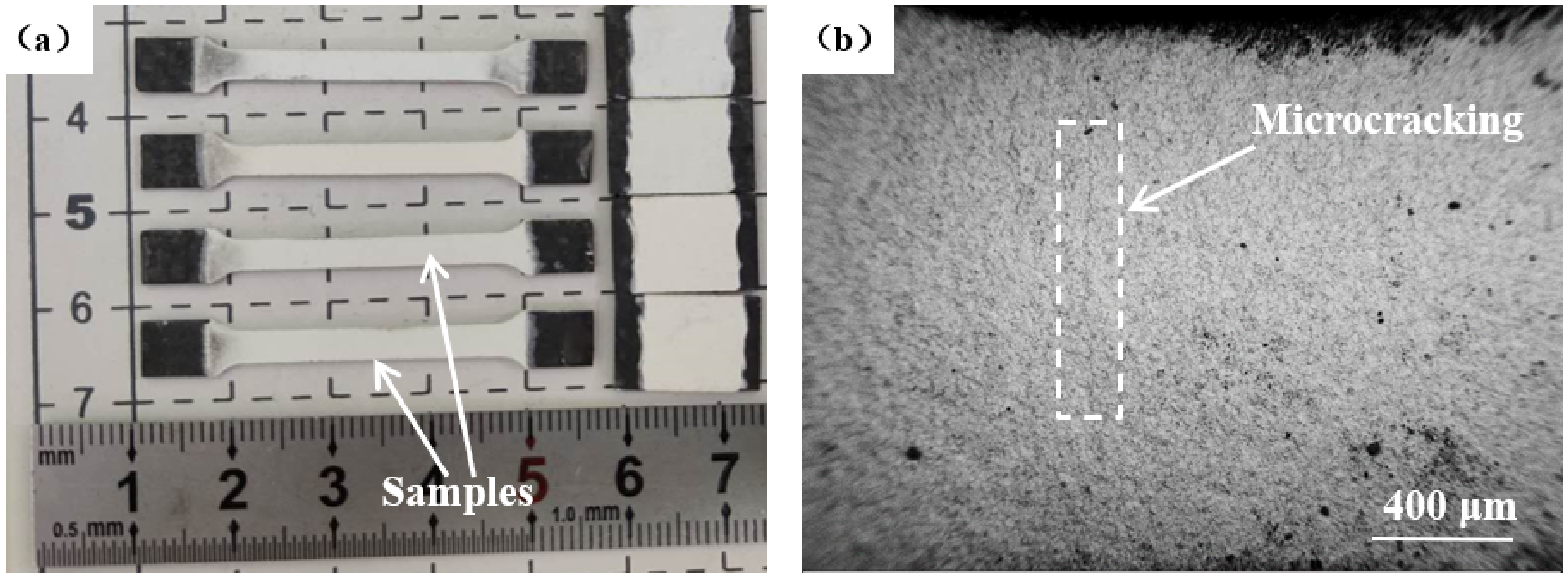
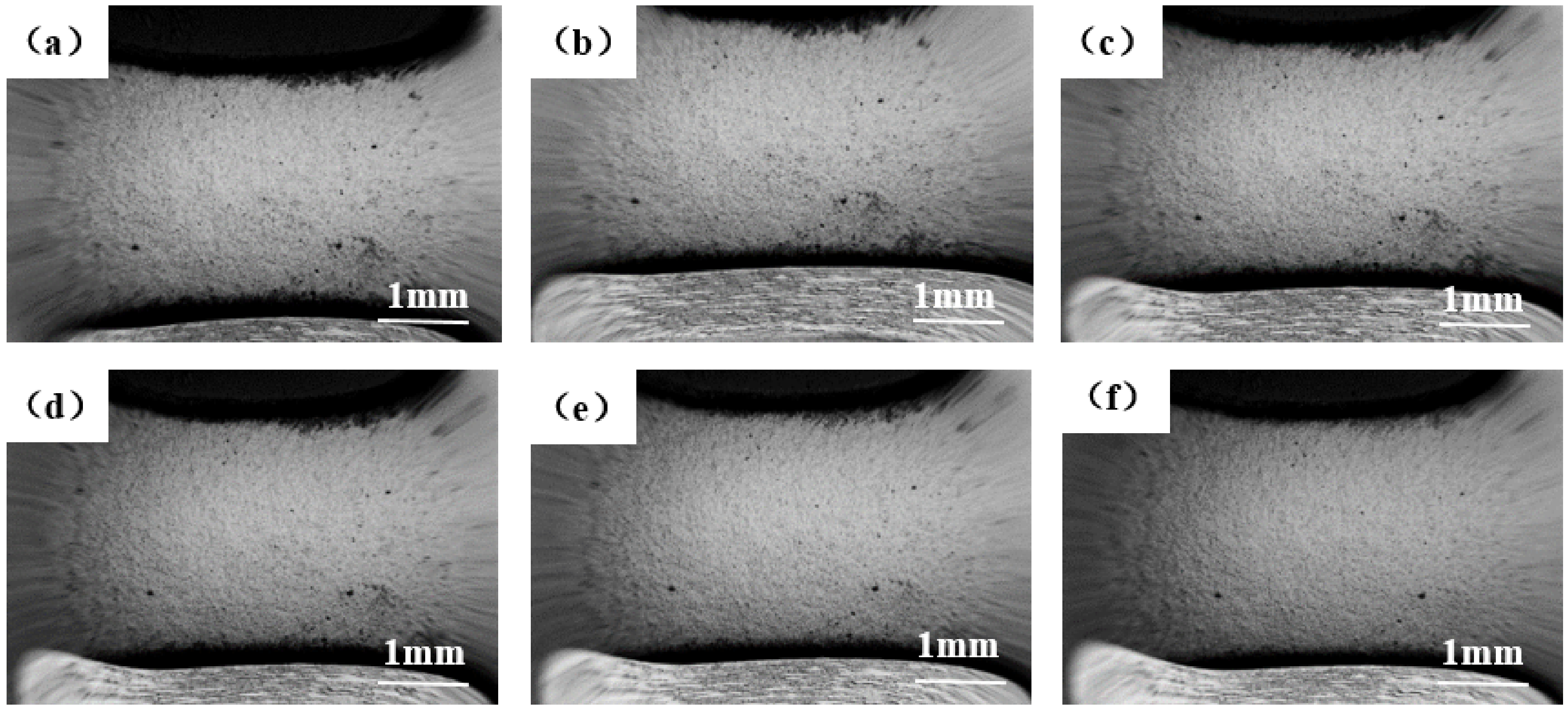
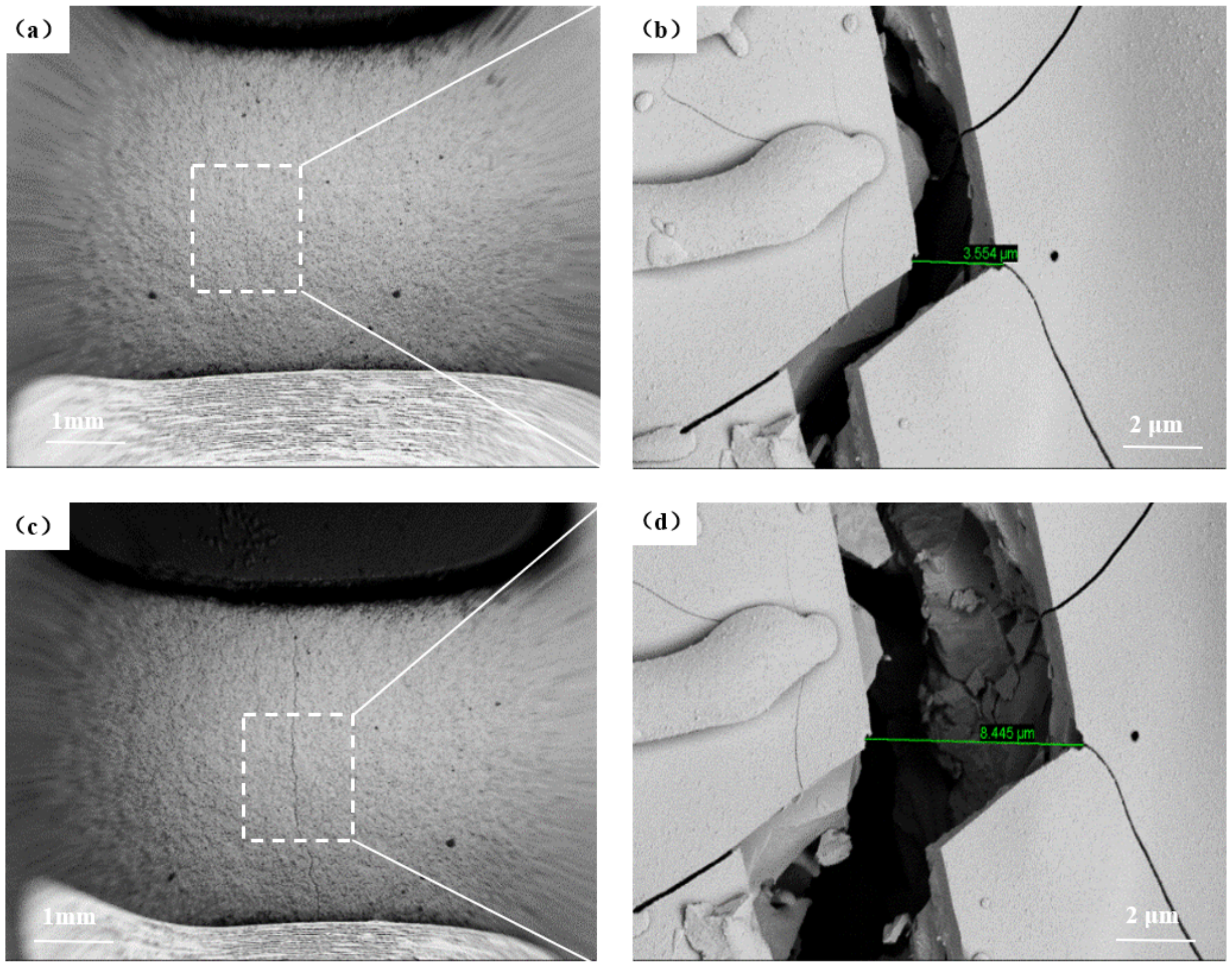
3.2. In Situ Microscopic Morphology of the EBCS under Temperature and Load Conditions

To investigate the effect of temperature on microcrack extension, the specimens were heated to the target temperature at 5 °C/min, holding the specimen at the desired temperature for 5 min. Different target temperatures were selected for microscopic in situ observation. From Figure 3, it can be observed that the in situ microscopic morphology of the specimens at temperatures of 111 °C, 213 °C, 323 °C, 430 °C, 528 °C and 766 °C shows that no significant extension of the surface cracks was observed under low-magnification conditions.
When magnification was increased, microcracks on the surface of the coated specimens were observed in situ. The same temperature series as above was selected for the microscopic in situ observation of the specimens. Figure 4 depicts the in situ microscopic morphology of the specimens at temperatures of 111 °C, 213 °C, 323 °C, 430 °C, 528 °C and 766 °C. Even at higher magnification, no crack extension behavior was observed, suggesting that the temperature increase did not lead to microcrack extension and elongation and that the effect of temperature change on cracking was limited under the condition of simply increasing the temperature without the addition of a tensile load.
To investigate the effect of different loads on the growth of microcracks at high temperature, the samples were loaded according to the loading curve in Figure 5 while being held at a high temperature of 766 °C. In situ microscopy was used to observe the samples as the load was varied.
Figure 6 shows that when the samples were loaded with 10 N, 50 N, 100 N and 150 N at 766 °C, no crack propagation on the coating surface was observed. Then, when further loaded to 250 N, the widening and propagation of cracks on the coating surface was observed, especially at 300 N. This observation showed that microcracks can expand under coupled high-temperature and load conditions. As can be seen in Figure 5 and Figure 6, crack propagation when loaded to 340 N resulted in the fracture failure of the specimens.
As the in situ imaging magnification was increased, microcrack propagation was clearly observed on the coated sample surfaces when subjected to tensile loading at the high temperature of 766 °C. As shown in Figure 7, the microcracks gradually widened with the application of increasing the load to the coatings. In Figure 8, the width of the crack on the coating surface increased from 3.55 µm to 5.89 µm, indicating that the loading force had a significant effect on crack propagation and the fracture failure of the sample at 766 °C.

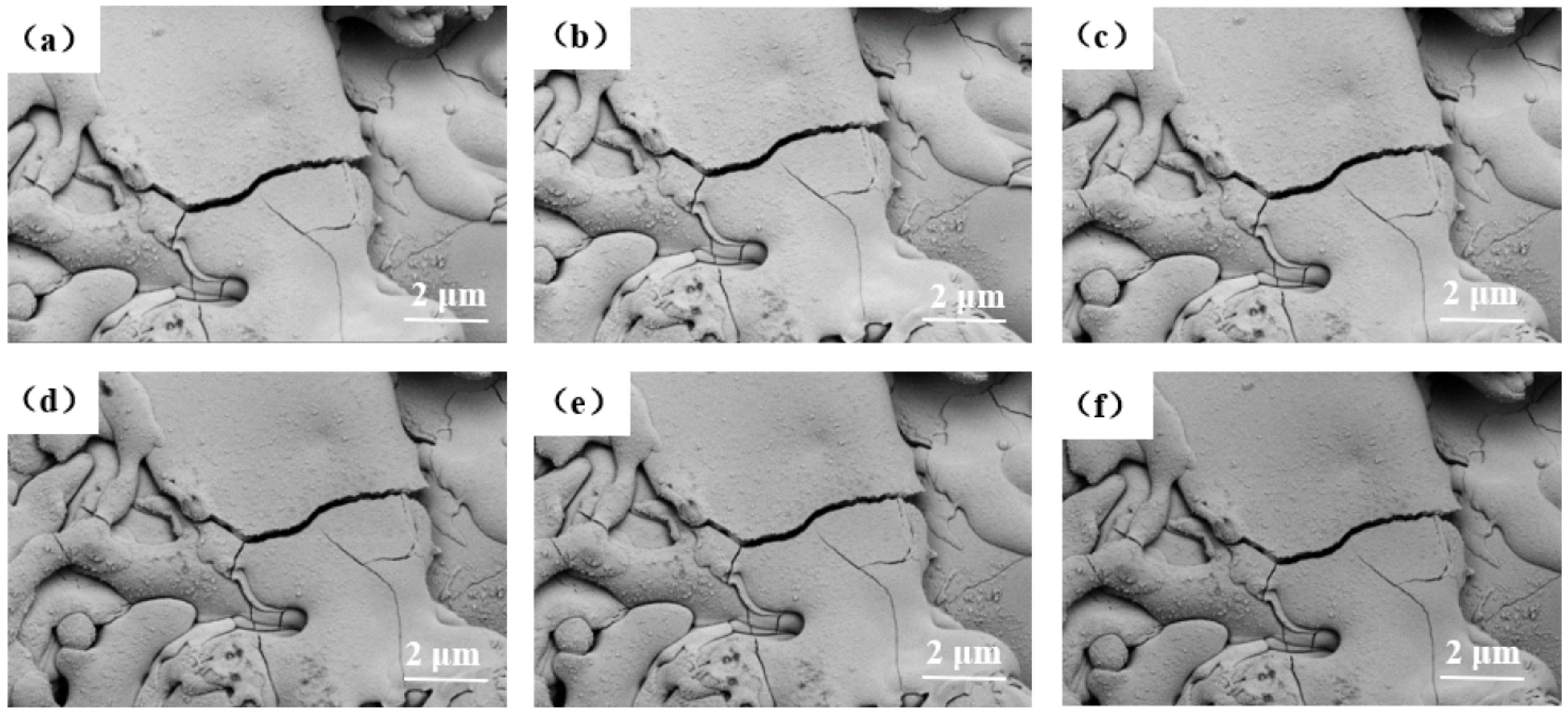
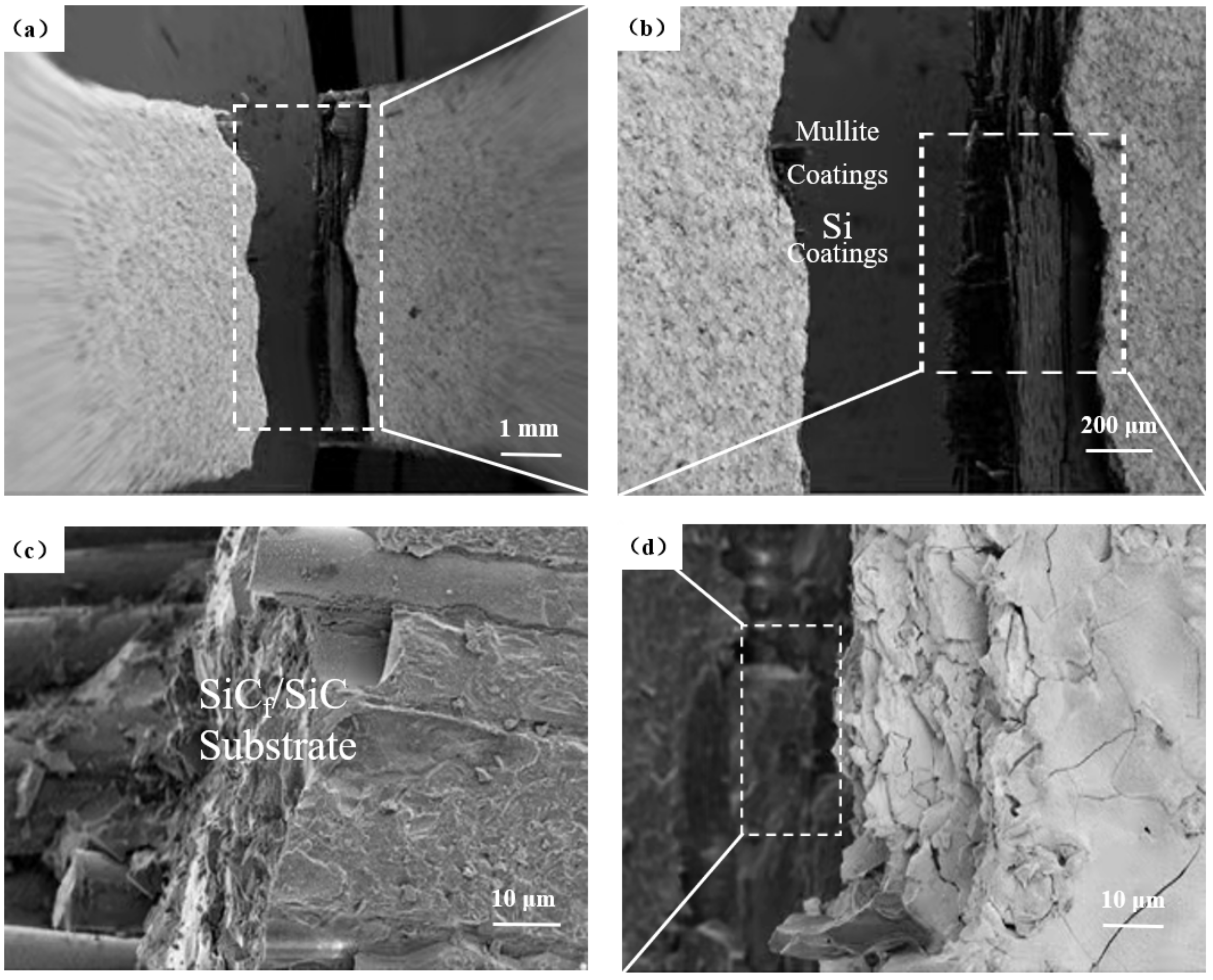
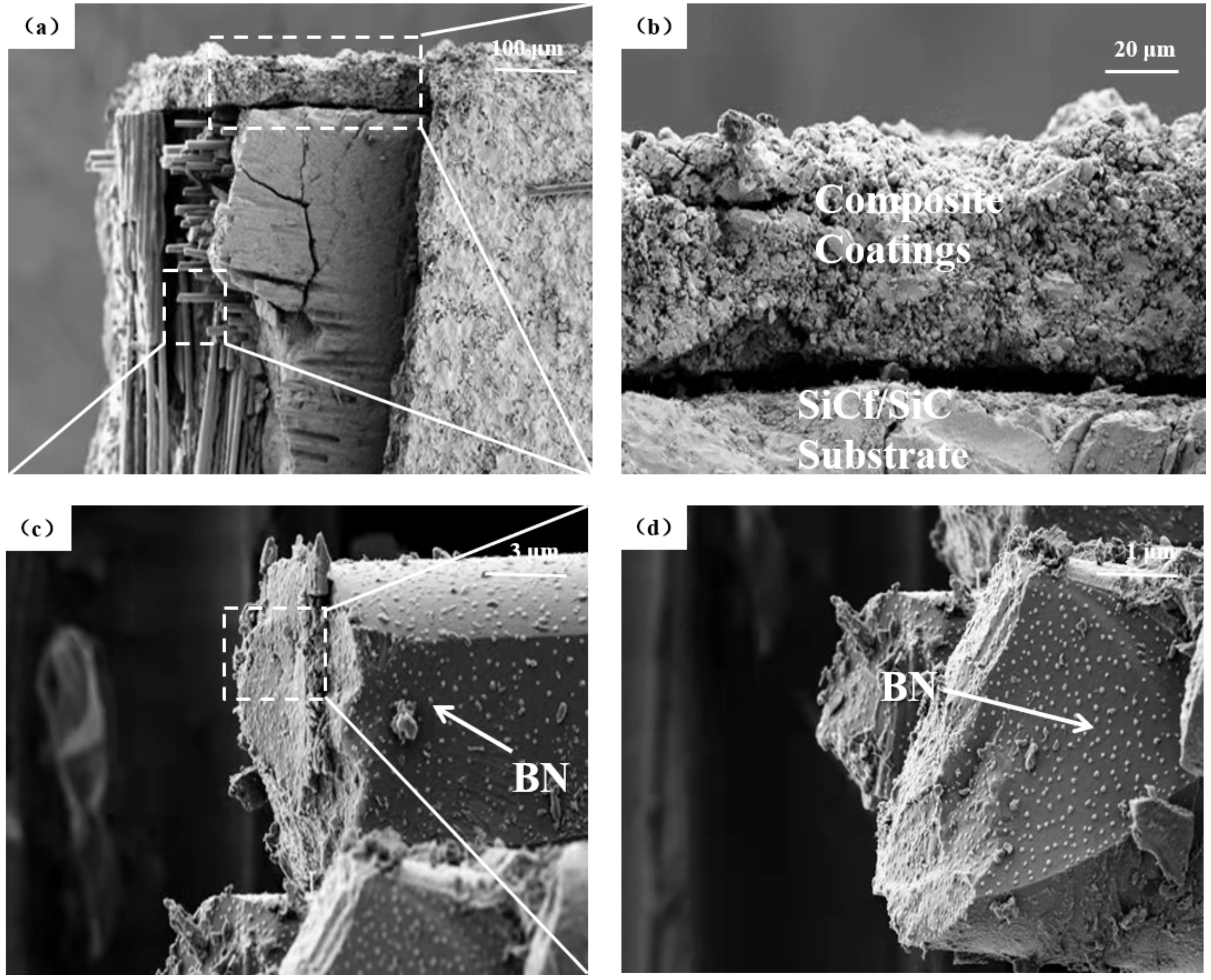
3.3. Microstructure of Fracture

When loaded to 340 N at a high temperature of 766 °C, the sample ruptured. The microscopic features of the fracture are shown in Figure 9. Upon magnification, damage to both the coating and the substrate can be observed. Figure 9b,c show that the fracture of the coating and the substrate exhibits a step-like pattern, indicating that the fracture extends from the surface to the interior of the coating and then reaches the substrate interface, resulting in the fracture of the coating.
The morphology of the fracture surface in a failed specimen can be more clearly observed in Figure 10. Figure 10a shows the detailed step-like pattern of the fracture as it propagated between the coating and the substrate. Upon further magnification (Figure 10b), it can be seen that large peeling cracks developed between the coating and the substrate, indicating that cracks formed between the coating and the substrate due to the coupled effect of high-temperature and tensile loading before the substrate ruptured. The substrate rupture surface shows features consistent with fibrous tearing after fracture, although no significant oxidation was observed on the surface of the substrate. Even so, there was clear evidence of delamination between the coating and the substrate, with the coating showing brittle fracture characteristics. The surface coating and the substrate fractured differently under the coupled application of high temperature and load, with the coating providing effective high-temperature protection.

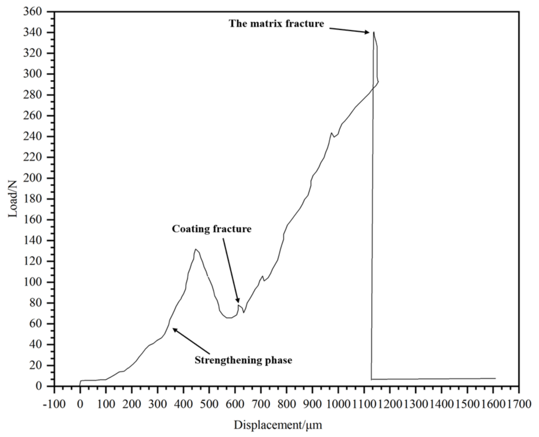
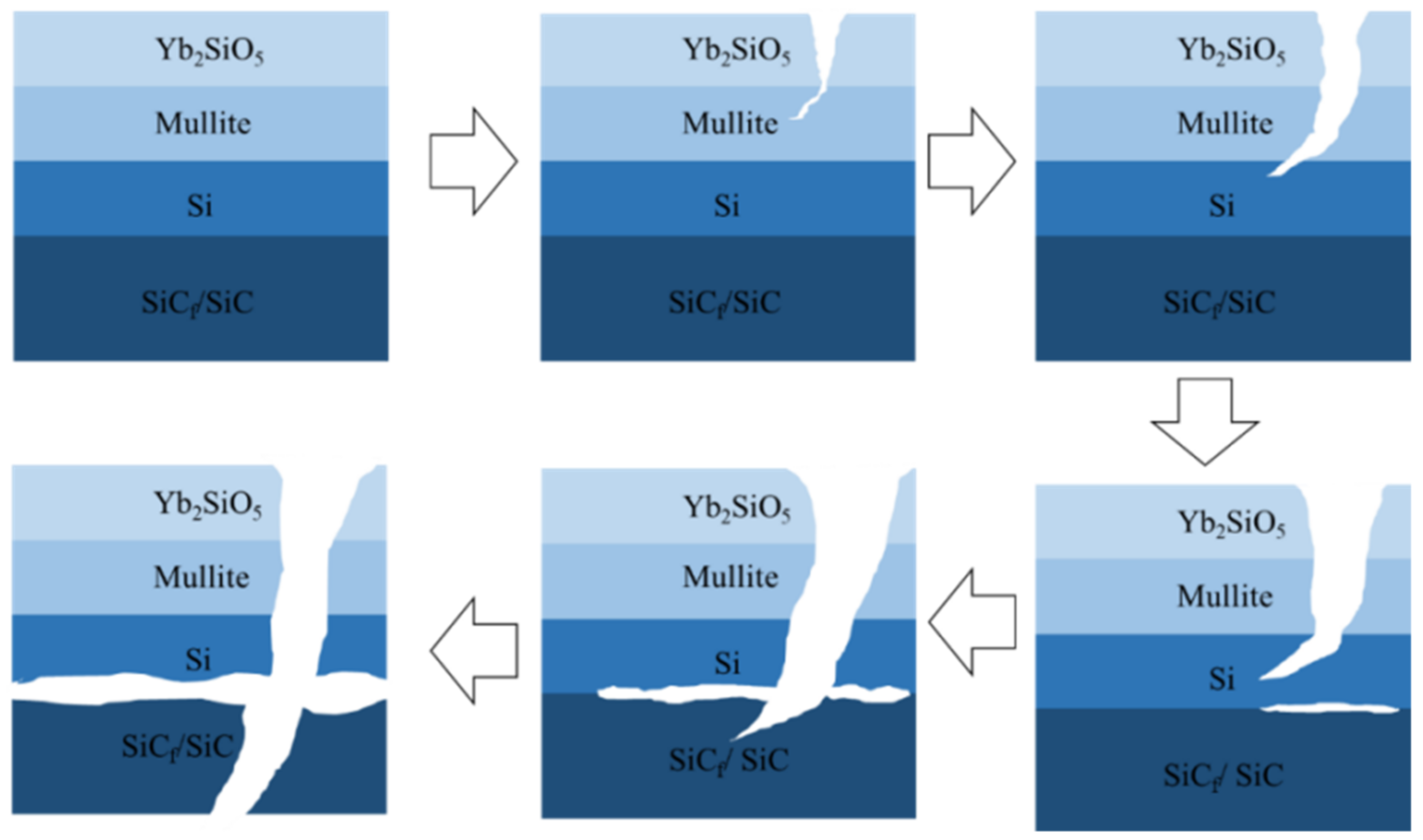
3.4. Failure Mechanism

Figure 11 is a schematic diagram of the fracture mechanism of the sample. The failure mechanism of the coating is divided into two parts: the fracture and spalling of the coating caused by a penetrating crack that develops on the face, followed by interlayer crack fusion due to the penetrating of the crack through subsequent layers. After the EBC is coupled with high temperature, the sharp temperature difference leads to microcracks on the surface and the formation of microcracks at the coating interface. After a period of time, the cracks extend to the interface of the coating, with the two crack types meeting and fusing with each other, which intensifies the damage to the SiCf/SiC substrate and finally leads to substrate rupture.

4. Conclusions

Si/3Al2O30–2SiO2/Yb2SiO5 EBC composite coatings are characterized by the presence of microporosity and microcracks due to phase changes during processing and differences in the thermal expansion coefficients of individual phases. These coating defects cannot be eliminated by applying initial and subsequent heat treatments to the initial powder and coating, respectively. The results of this work show that as the temperature of a coated sample increased from room temperature to 766 °C in the absence of an applied tensile load, no significant crack extension was observed on the surface of the coating, indicating that the effect of the temperature on sample failure was negligible. In contrast, under coupled high-temperature and tensile load conditions, the sample ruptured at a load of 340 N and a high temperature of 766 °C, indicating that the coated sample is more likely to fail under the application of the tensile load at high temperature. Step-like fractures indicate the fracture and spalling of the coating caused by surface cracks extending from the coating surface to its interior. The delamination, large crack formation and step-like behavior of the crack in the coating to the substrate are characteristic features of crack development between the coating and the substrate under coupled high-temperature and load conditions. The formation and extension of the cracks in both portions of the composite eventually leads to full specimen rupture.

Author Contributions

Conceptualization, validation, and writing—original draft preparation, J.Z.; investigation, software, validation, and data curation, D.Y.; methodology, project administration, and data curation, J.L.; investigation, writing—review and editing, and supervision, X.Z.; formal analysis, investigation, and visualization, X.L.; software, investigation, X.L. All authors have read and agreed to the published version of the manuscript.

Funding

We would like to acknowledge the financial support from the National Natural Science Foundation of China (52172067,52161033), the Guangdong Province Outstanding Youth Foundation (2021B1515020038), and Guangdong Academy of Sciences Program (2020GDASYL–20200104030), and the Guangxi Natural Science Foundation (No. 2020GXNSFAA297082).

Institutional Review Board Statement

Not applicable.

Informed Consent Statement

Not applicable.

Data Availability Statement

Data is contained within the article.

Conflicts of Interest

The authors declare no conflict of interest.

References

  1. Chen, K.; Seo, D.; Canteenwalla, P. The Effect of High-Temperature Water Vapour on Degradation and Failure of Hot Section Components of Gas Turbine Engines. Coatings 2021, 11, 1061. [Google Scholar] [CrossRef]
  2. Lee, K.N.; Eldridge, J.I.; Robinson, R.C. Residual stresses and their effects on the durability of environmental barrier coatings for SiC ceramics. J. Am. Ceram. Soc. 2005, 88, 3483–3488. [Google Scholar] [CrossRef]
  3. Arnal, S.; Fourcade, S.; Mauvy, F.; Rebillat, F. Design of a new yttrium silicate Environmental Barrier Coating (EBC) based on the relationship between microstructure, transport properties and protection efficiency. J. Eur. Ceram. Soc. 2022, 42, 1061–1076. [Google Scholar] [CrossRef]
  4. Presby, M.J.; Harder, B.J. Solid particle erosion of a plasma spray–physical vapor deposition environmental barrier coating in a combustion environment. Ceram. Int. 2021, 47, 24403–24411. [Google Scholar] [CrossRef]
  5. Schmitt, M.P.; Harder, B.J.; Wolfe, D.E. Process-structure-property relations for the erosion durability of plasma spray-physical vapor deposition (PS-PVD) thermal barrier coatings. Surf. Coat. Technol. 2016, 297, 11–18. [Google Scholar] [CrossRef] [Green Version]
  6. Kong, L.; Karatchevtseva, I.; Gregg, D.J.; Blackford, M.G.; Holmes, R.; Triani, G. Gd2Zr2O7 and Nd2Zr2O7 pyrochlore preparedby aqueous chemical synthesis. J. Eur. Ceram. Soc. 2013, 33, 3273–3285. [Google Scholar] [CrossRef]
  7. Smialek, J.L. Compiled furnace cyclic lives of EB-PVD thermal barrier coatings. Surf. Coat. Technol. 2015, 276, 31–38. [Google Scholar] [CrossRef] [Green Version]
  8. Zhong, X.; Niu, Y.; Li, H.; Zhu, T.; Song, X.; Zeng, Y.; Zheng, X.; Ding, C.; Sun, J. Comparative study on high-temperature performance and thermal shock behavior of plasma-sprayed Yb2SiO5 and Yb2Si2O7 coatings. Surf. Coat. Technol. 2018, 349, 636–646. [Google Scholar] [CrossRef]
  9. Harder, B.J. Oxidation performance of Si–HfO2 environmental barrier coating bond coats deposited via plasma spray-physical vapor deposition. Surf. Coat. Technol. 2020, 384, 125311. [Google Scholar] [CrossRef]
  10. Rezanka, S.; Somsen, C.; Eggeler, G.; Mauer, G.; Vaßen, R.; Guillon, O. A TEM Investigation of Columnar-Structured Thermal Barrier Coatings Deposited by Plasma Spray-Physical Vapor Deposition (PS-PVD). Plasma Chem. Plasma Process. 2018, 38, 791–802. [Google Scholar] [CrossRef]
  11. He, W.; Mauer, G.; Schwedt, A.; Guillon, O.; Vaßen, R. Advanced crystallographic study of the columnar growth of YZS coatings produced by PS-PVD. J. Eur. Ceram. Soc. 2018, 38, 2449–2453. [Google Scholar] [CrossRef]
  12. Mauer, G.; Vaben, R. Conditions for nucleation and growth in the substrate boundary layer at plasma spray-physical vapor deposition (PS-PVD). Surf. Coat. Technol. 2019, 371, 417–427. [Google Scholar] [CrossRef]
  13. Zhang, X.F.; Song, J.B.; Deng, Z.Q.; Wang, C.; Niu, S.P.; Liu, G.; Deng, C.M.; Deng, C.G.; Liu, M.; Zhou, K.S.; et al. Interface evolution of Si/Mullite/Yb2SiO5 PS-PVD environmental barrier coatings under high temperature. J. Eur. Ceram. Soc. 2020, 40, 1478–1487. [Google Scholar] [CrossRef]
  14. Blagoeva, D.T.; Hegeman, J.B.J.; Jong, M.; Heijna, M.C.R.; de Vincente, S.M.G.; Bakker, T.; ten Pierick, P.; Nolles, H. Characterisation of 2D and 3D Tyranno SA 3 CVI SiCf/SiC composites. Mater. Sci. Eng. A 2015, 638, 305–313. [Google Scholar] [CrossRef]
  15. Kedir, N.; Garcia, E.; Kirk, C.; Gao, J.; Guo, Z.; Zhai, X.; Sun, T.; Fezzaa, K.; Sampath, S.; Chen, W.W. Impact damage of narrow silicon carbide (SiC) ceramics with and without environmental barrier coatings (EBCs) by various foreign object debris (FOD) simulants. Surf. Coat. Technol. 2021, 407, 126779. [Google Scholar] [CrossRef]
  16. Lv, B.; Jin, X.; Cao, J.; Xu, B.; Wang, Y.; Fang, D. Advances in numerical modeling of environmental barrier coating systems for gas turbines. J. Eur. Ceram. Soc. 2020, 40, 3363–3379. [Google Scholar] [CrossRef]
  17. Nasiri, N.A.; Patra, N.; Ni, N.; Jayaseelan, D.D.; Lee, W.E. Oxidation behaviour of SiC/SiC ceramic matrix composites in air. J. Eur. Ceram. Soc. 2016, 36, 3293–3302. [Google Scholar] [CrossRef]
  18. Tejero-Martin, D.; Bennett, C.; Hussain, T. A review on environmental barrier coatings: History, current state of the art and future developments. J. Eur. Ceram. Soc. 2021, 41, 1747–1768. [Google Scholar] [CrossRef]
  19. Al Nasiri, N.; Patra, N.; Pezoldt, M.; Colas, J.; Lee, W.E. Investigation of a single-layer EBC deposited on SiC/SiC CMCs: Processing and corrosion behaviour in high-temperature steam. J. Eur. Ceram. Soc. 2019, 39, 2703–2711. [Google Scholar] [CrossRef]
  20. Ramasamy, S.; Tewari, S.N.; Lee, K.N.; Bhatt, R.T.; Fox, D.S. Mullite–gadolinium silicate environmental barrier coatings for melt infiltrated SiC/SiC composites. Surf. Coat. Technol. 2011, 205, 3578–3581. [Google Scholar] [CrossRef]
  21. Hu, Q.; Zhou, X.; Tu, Y.; Lu, X.; Huang, J.; Jiang, J.; Deng, L.; Dong, S.; Cao, X. High-temperature mechanical properties and oxidation resistance of SiCf/SiC ceramic matrix composites with multi-layer environmental barrier coatings for turbine applications. Ceram. Int. 2021, 47, 30012–30019. [Google Scholar] [CrossRef]
  22. Lee, K.N.; Fox, D.S.; Bansal, N.P. Rare earth silicate environmental barrier coatings for SiC/SiC composites and Si3N4 ceramics. J. Eur. Ceram. Soc. 2005, 25, 1705–1715. [Google Scholar] [CrossRef]
  23. Qian, Y.; Du, L.; Zhang, W. Preparation of spherical Yb2SiO5 powders for thermal-spray coating. Particuology 2009, 7, 368–372. [Google Scholar] [CrossRef]
  24. Zou, B.; Khan, Z.S.; Fan, X.; Huang, W.; Gu, L.; Wang, Y.; Xu, J.; Tao, S.; Yang, K.; Ma, H.; et al. A new double layer oxidation resistant coating based on Er2SiO5/LaMgAl11O19 deposited on C/SiC composites by atmospheric plasma spraying. Surf. Coat. Technol. 2013, 219, 101–108. [Google Scholar] [CrossRef]
  25. Zou, B.; Khan, Z.S.; Gu, L.; Fan, X.; Huang, W.; Wang, Y.; Zhao, Y.; Wang, C.; Yang, K.; Ma, H.; et al. Microstructure, oxidation protection and failure mechanism of Yb2SiO5/LaMgAl11O19 coating deposited on C/SiC composites by atmospheric plasma spraying. Corros. Sci. 2012, 62, 192–200. [Google Scholar] [CrossRef]
  26. Lee, K.N.; Waters, D.L.; Puleo, B.J.; Garg, A.; Jennings, W.D.; Costa, G.; Sacksteder, D.E. Development of oxide-based High temperature environmental barrier coatings for ceramic matrix composites via the slurry process. J. Eur. Ceram. Soc. 2021, 41, 1639–1653. [Google Scholar] [CrossRef]
  27. Feng, F.-J.; Jang, B.-K.; Park, J.Y.; Lee, K.S. Effect of Yb2SiO5 addition on the physical and mechanical properties of sintered mullite ceramic as an environmental barrier coating material. Ceram. Int. 2016, 42, 15203–15208. [Google Scholar] [CrossRef]
  28. Ouyang, Z.; Yang, Y.; Sun, J. Electroluminescent Yb2O3:Er and Yb2Si2O7:Er nanolaminate films fabricated by atomic layer deposition on silicon. Opt. Mater. 2018, 80, 209–215. [Google Scholar] [CrossRef]
  29. Chen, P.; Pan, L.; Xiao, P.; Li, Z.; Pu, D.; Li, J.; Pang, L.; Li, Y. Microstructure and anti-oxidation properties of Yb2Si2O7/SiC bi-layer coating for C/SiC composites. Ceram. Int. 2019, 45, 24221–24229. [Google Scholar] [CrossRef]
Figure 1. Preparation of the EBC by the PS-PVD thermal spraying process. (a) Schematic diagram of the EBC structure. SEM images of each coating powder in the EBC: (b) Si; (c) 3Al2O3 2SiO2; and (d) Yb2SiO5.
Coatings 12 00655 g001
Figure 2. Specimen after spraying: (a) macro-scale photo; and (b) SEM micrograph.
Coatings 12 00655 g002
Figure 3. In situ SEM images of specimens at different temperatures without load: (a) 111 °C; (b) 213 °C; (c) 323 °C; (d) 430 °C; (e) 528 °C; and (f) 766 °C.
Coatings 12 00655 g003
Figure 4. Locally enlarged view of a sample observed using in situ SEM at different temperatures without load: (a) 111 °C; (b) 213 °C; (c) 323 °C; (d) 430 °C; (e) 528 °C; and (f) 766 °C.
Coatings 12 00655 g004
Figure 5. Loading curve of a coated specimen at 766 °C.
Coatings 12 00655 g005
Figure 6. In situ SEM of a sample held at 766 °C and subjected to a variable loading profile: (a) 10 N; (b) 50 N; (c) 100 N; (d) 150 N; (e) 250 N; and (f) 300 N.
Coatings 12 00655 g006
Figure 7. In situ SEM locally enlarged view of a sample held at 766 °C and subjected to a variable loading profile: (a) 10 N; (b) 50 N; (c) 100 N; (d) 150 N; (e) 250 N; and (f) 300 N.
Coatings 12 00655 g007
Figure 8. In situ SEM surface crack propagation when the specimen was held at 766 °C and subjected to a variable loading profile: (a,b) 250 N; (c,d) 300 N.
Coatings 12 00655 g008
Figure 9. In situ SEM reveals microscopic features of the fracture developed under a load of 340 N in a sample held at 766 °C: (a) fracture micromorphology; (b) local magnification of fracture micromorphology; (c) local magnification of fractured matrix; and (d) local magnification of coating portion of fracture.
Coatings 12 00655 g009
Figure 10. The morphology of the fracture developed under a load of 340 N in a sample held at 766 °C: (a) local fracture morphology; (b) local interface between the coating and substrate after fracture; (c) fracture features of a matrix fiber; and (d) enlarged view of the fracture surface of the matrix fiber.
Coatings 12 00655 g010
Figure 11. Schematic diagram of the failure mechanism of the specimen with the EBC after the thermal mechanical coupling test.
Coatings 12 00655 g011
Table 1. Processing parameters of PS-PVD for each coating.
CoatingsCurrent(A)Ar
(L/min)
H2
(L/min)
Spraying
Distance
(mm)
Scanning
Speed
(mm/s)
Si6004031301000
Mullite63030121301000
Yb2SiO563030121301000
Publisher’s Note: MDPI stays neutral with regard to jurisdictional claims in published maps and institutional affiliations.

