Article

Research on Film-Forming Characteristics and Mechanism of Painting V-Shaped Surfaces

1
Department of Petroleum, Army Logistics University, Chongqing 401331, China
2
State Key Laboratory of NBC Protection for Civilian, Beijing 100097, China
*
Author to whom correspondence should be addressed.
These authors contributed equally to this work.
Coatings 2022, 12(5), 658; https://doi.org/10.3390/coatings12050658
Submission received: 6 April 2022 / Revised: 5 May 2022 / Accepted: 6 May 2022 / Published: 12 May 2022

Abstract

:
Painting a V-shaped surface, which is widely found in various facilities and equipment, often results in poor coating quality, which may be caused by an insufficient understanding of film-forming characteristics and mechanism. In this study, computational fluid dynamic (CFD) simulations were carried out for in-depth research on the film-forming characteristics and mechanism of painting V-shaped surfaces. The mathematical model of film formation was established with the Euler–Euler method, and the unstructured grids and adaptive-mesh refinement were adopted to discretize the computational domain. By solving the model, the coating thickness distribution law and flow-field characteristics of spraying a V-shaped surface were obtained. When painting a V-shaped surface with an angle less than 180°, the coating thickness distribution appeared as two peaks, instead of the single peak that appeared when painting a flat wall. As the V-shaped angle decreased, the coating thickness became thinner. The peak position gradually shifted to both sides, and the thickness distribution became wider. Analysis of the spray flow-field characteristics revealed the thickness distribution mechanism, by whichthe geometric characteristics of the V-shaped surface changed the near-wall distribution of the flow field. When the V-shaped angle decreased, the pressure peak at the center of the V-shaped surface and the eccentric pressure peaks that formed on both sides increased. The near-wall paint fluid was confined between the central pressure peak and the off-center pressure peak, resulting in paint droplets depositing between the pressure peaks and double-peak distribution of the coating thickness forming on the V-shaped surface. The spraying experiments verified the correctness of the numerical simulations, film-forming characteristics, and corresponding mechanism, which are of great significance for efficient and high-quality spraying on V-shaped surfaces.

1. Introduction

It is always a complicated and difficult research topic to improve the quality of robot spraying on complex surfaces [1,2,3,4]. Paint’s film-forming characteristics on some complex surfaces have been studied, such as cylindrical surfaces [5], arc surfaces [6], spherical surfaces [7], etc. However, the film-forming characteristics when painting a V-shaped surface cannot be found in the literature. As a typical complex surface with large curvature, a V-shaped surface is widely found in various facilities and equipment. It has the characteristics of sudden change in structural connection and limitation of working space, which seriously affect the trajectory planning of the robot spray gun and the quality of the coating [8]. Research on the film-forming characteristics and mechanism of painting V-shaped surfaces is of great theoretical and practical significance in revealing the film-forming mechanisms and rules of spraying complex free-form surfaces with large curvature, optimizing the spray gun trajectory, improving the coating quality, etc.
To date, research on the film-forming characteristics and mechanism of painting a V-shaped surface is conducted using empirical models [9,10,11]. First, the empirical formulae of the coating growth rate on a flat plate is identified as the result of a painting experiment. The empirical formula for a V-shaped surface is then obtained according to the area enlargement theorem of differential geometry. This approach can provide a theoretical basis for robot trajectory planning when painting a V-shaped surface. However, this method has an implicit assumption that the spray streamline is straight without considering the change in flow-field characteristics of V-shaped surfaces and the influence of the surface shape on the film-forming process. Based on the reasons above, a large error may arise when using this approach to conduct research on the film-forming characteristics and mechanism of painting V-shaped surfaces.
In recent years, with the development of the computational fluid dynamics (CFD) theory and the continuous improvement of supporting platforms [12], researchers have applied a CFD numerical simulation to studying the film-forming characteristics of air spraying [13,14,15]. For the simulation of the gas–liquid phase flow in air spraying, the main CFD methods are the Euler–Lagrange approach [16,17] and the Euler–Euler approach [18,19,20]. In the numerical simulation, the Euler–Lagrange approach can separately solve the flow movements of gas–liquid, two phases in the spray flow field, and obtain the trajectory of a single droplet and the velocity and pressure of the liquid and gas phases [16,21,22]. However, the coupling effect of the gas and liquid phases is ignored, and the overall situation of a spray flow field is hard to describe. While the Euler–Euler approach regards paint droplets as pseudo-fluid, droplets and gas spatially coexist and are interpenetrating continua [15,23]. In this way, the various turbulent transport processes of the paint phase and the influence of droplets on gas can be fully considered, ensuring the accuracy of the film-forming simulation. In addition, the computational requirements and time cost of the Euler–Euler approach are lower than the Euler–Lagrange approach. Therefore, the Euler–Euler approach seems more suitable for simulating the film-forming process of painting V-shaped surfaces.
In this study, numerical simulations using a mathematical model established with the Euler–Euler approach were carried out when painting the V-shaped surfaces of different angles. The mathematical model was solved by the SIMPLE algorithm of the phase solver based on pressure correction. The coating thickness distribution law and flow-field characteristics of the V-shaped surface spraying were obtained, and their causes were analyzed. Finally, the correctness of the spraying numerical simulations, coating thickness characteristics, and corresponding mechanism were verified with spraying experiments.

2. Mathematical Model

The film-forming model is used to describe the motion process of paint and the air phases in the spray flow field. In this paper, the spray flow-field model and spray deposition model were established in the Euler coordinates.

2.1. Spray Flow-Field Model

2.1.1. Two-Phase Governing Equation

When establishing the two-phase flow-field model, it was assumed that there was no energy exchange between the spray flow field and the surrounding air, and the energy equation could not be established. The mass and momentum conservation equations are as follows [5]:
α w ρ w t + · ( α w ρ w u w ) = 0
t ( α w ρ w u w ) + · ( α w ρ w u w u w ) = α w p + · τ w + F l , g + α w ρ w g
where α w , ρ w , and u w are the volume fraction, density (kg/m3), and velocity (m/s) of w phase, respectively. When w is replaced by l or g , it represents the paint or air phase, respectively. p is the total pressure generated by two phases, (N/m2); τ w is the viscous stress of w phase, (N/m2); F l , g and g represent the interphase force (N/m2) between gas and liquid and the local acceleration (m/s2) of gravity, respectively.

2.1.2. Turbulence Model

Fogliati et al. [23] found that the spray shape simulated by the realizable κ ε model was most consistent with actual observation results through the contrast calculations of a variety of turbulence models. The transport equation of turbulent kinetic energy κ (m2/s2) and the turbulent kinetic energy dissipation rate ε (m2/s3) in the realizable κ ε model are:
( ρ k ) t + ( ρ k u ¯ j ) x j = x j [ ( μ + μ t σ k ) k x j ] + G k ε ρ
( ρ ε ) t + ( ρ ε u ¯ j ) x j = x j [ ( μ + μ t σ ε ) ε x j ] + C 1 ρ E ε C 2 ρ ε 2 k + ε ν
where ν is kinematic viscosity, (m2/s) ν = μ / ρ . μ is dynamic viscosity (N·s/m2). Additional empirical coefficients are: σ k = 1.0 , σ ε = 1.2 , C 2 = 1.9 , C 1 = max ( 0.43 , η η + 5 ) , and η = k ε 2 E i j · E i j . E represents the empirical constant, for which the value is 9.793. G k is the production of turbulent kinetic energy κ generated by the average velocity gradient. The calculation expression is:
G k = μ t ( u i x j + u j x i ) u i x j

2.2. Paint Deposition Model

The spray deposition model was established, including mass and momentum conservation of the liquid-film and source equations.
The liquid-film governing equations are as follows [5]:
ρ L h t + · ( ρ L h u L ) = m ˙ L
( ρ L h u L ) t + · ( ρ L h u L u L ) = h p L + g τ ρ L h + 3 2 ρ L τ L s 3 μ L h ρ L u L + q ˙ L
The mass source term and momentum source term of liquid film are:
m ˙ L = α L ρ L u L n A
q ˙ L = m ˙ L u L
where ρ L is the density of liquid film, (kg/m3); h is the thickness of liquid film, (m); u L is the liquid-film average velocity, (m/s); p L is the flow-field pressure, (Pa); τ L s is the viscous shear force at the interface between air and liquid film, (N/m2); u L n is the wall normal velocity of droplet phase, (m/s).

3. Paint Film-Forming Simulation

3.1. Computational Domain Setting and Meshing

As shown in Figure 1, the geometric model of the air cap of a spray gun is a simplified one based on the prototype of the experiment. The corresponding aperture parameters are outlined in Table 1.
According to the size of the workpiece to be sprayed in the experiment and the requirement of the simulation calculation, the size of the 180° V-shaped surface (flat wall) was set as 700 × 300 mm2. The coordinate system of the 3D air cap model was established (Figure 2), in which the coordinate origin was located at the center of the bottom surface. When painting a V-shaped surface, two painting patterns can be applied as shown in Figure 3. A V-shaped surface has similar effects on the characteristics of the spray flow field along the X and Y axes. In addition, there is a larger size in the Y-axis direction, which is more convenient for flow-field observation and analysis. Therefore, only the perpendicular mode was analyzed in this paper (Figure 3a).
The computational domain of the spray flow field was discretized by an unstructured grid. For the orifice area of the air cap, central area, and spray area where the velocity gradient changed greatly, the mesh adaptive mode was adopted for mesh refinement in order to ensure the simulation accuracy and control the total number of grids. The rest of the flow field was matched with a relatively sparse mesh due to its wide range and relatively simple structure. As shown in Figure 4, the total number of grids in the whole computational domain was 3.33 million, with the minimum grid size of 1 × 10⁻⁶ mm and the maximum of 3 mm.

3.2. Initial and Boundary Conditions

The numerical simulation was carried out by the software Fluent 19.0. The Euler-Euler model was selected to track and solve the gas–liquid interface in the spray flow field. Air and paint were set as phase 1 and phase 2, respectively. The two-phase physical parameters are outlined in Table 2. The initial and boundary conditions were set as shown.
The paint inlet type was set as the mass flow inlet, with the mass flow rate, turbulent intensity, and hydraulic diameter being 1.32 × 10⁻³ kg/s, 5%, and 1.1 mm, respectively. The central atomization hole, auxiliary atomization hole, and side control hole were set as pressure inlets, and the gauge total pressures were 121.6 kPa, 110 kPa, and 121.6 kPa, respectively. All the turbulence intensity values of the air inlets were 5%. In addition, the hydraulic diameters were 0.4 mm, 0.6 mm, and 0.8 mm, respectively. The gravity acceleration of the spray flow field, the environmental pressure, the simulation time step, and the total spraying time were 9.8 m/s2, 1 standard atmospheric pressure, 1 × 10⁻⁴ s, and 0.5 s, respectively.
The two-phase governing equations were discretized by the fully implicit approach of finite volume method. The SIMPLE algorithm of the phase coupling based on pressure correction was used to solve the equations.

4. Results and Analysis

The information about the spray flow field and coating thickness can be obtained by numerical solution. This section first studied the distribution characteristics of the coating thickness on V-shaped surfaces with different angles. In this way, the mechanism of film thickness distribution was revealed by analyzing the spray flow field.
The coating thickness contours on V-shaped surfaces with different angles are shown in Figure 5. All coating thickness distribution was approximately elliptic, namely, the coating thickness distribution on the Y axis was wider than the distribution on the X axis. However, from Figure 5d–f, it can be clearly seen that the maximum values of film thickness appear on both sides of the V-shaped surface intersection line, and that the coating thickness distribution on each wall is quite different.
In order to better display the difference in coating thickness distribution on different walls, the wall coordinates were established, as Figure 6 shows. When painting the 180° V-shaped surface, the coating thickness peak value was located at the center and was clearly larger than the coating nearby, accompanied by a gradual decrease in thickness outwardly, as Figure 7 shows. With the decrease of the V-shaped angle, the peak values decreased, the coating thickness peaks appeared on both sides, and a double-peak distribution was presented.
The velocity contours of air and paint when painting V-shaped surfaces of different angles are shown in the Figure 8 and Figure 9. Under the effect of shaping air, the velocity distribution range of the Y–Z plane was noticeably larger than that of the X–Z plane. With the spray flow field developing downward, the axial velocities of fluids gradually decreased, and their distribution extended along the radial direction. Comparing the air and paint velocity contours on the same wall surface, the distribution range of air velocity was significantly larger than that of the paint velocity, due to the higher density and inertia of the paint.
To explore the mechanism of coating thickness distribution on different wall, the paint velocities were obtained from a line 10 mm away from the wall surface. Therewith, the normal component perpendicular to the wall’s surface and the tangential component parallel to the wall’s surface were calculated. The comparisons are shown in Figure 10andFigure 11. Since the spray flow field in the Y–Z plane was symmetrically distributed on the Z axis, only the data in the positive direction of the Y axis is shown.
In Figure 10, the maximum near-wall normal velocity of the 180° V-shaped surface is located at the center. With the V-shaped angle decreasing, the normal velocity of near-wall center decreased, and the maximum normal velocity gradually shifted outward. Since the coating thickness was proportional to the paint’s normal velocity perpendicular to the wall, the coating thickness distribution of the 180° V-shaped surface was a one-peak distribution. When painting V-shaped surfaces of angles less than 180°, the coating thickness distribution of the inner wall of the V-shaped surface presented a double-peak distribution, where the peak values appeared on both sides. As the V-shaped angle decreased, the peak thickness decreased, and the position shifted to both sides gradually.
Figure 11 shows that the near-wall tangential velocity of the 180° V-shaped surface was always positive, illustrating that the near-wall fluid flows outward from the center, whereas the near-wall tangential velocity of the V-shaped surface with an angle less than 180° was always negative. The smaller the V-shaped angle was, the greater the absolute value of tangential velocity became, indicating that the more near-wall fluid flowed toward the center. The streamlines of spray flow field (Figure 12) show these phenomena.
Figure 12a shows that the near-wall pressure distribution of painting the 180° V-shaped surface was large in the center and small on both sides. As depicted in Figure 12 and Figure 13, the peak pressure at the center increased gradually with the decrease of the V-shaped angle, exhibiting an off-center pressure peak on each side. The positions of the off-center pressure peaks gradually shifted outward, and their values increased with the decrease of the V-shape angle.
The phenomenon above can be explained. As the V-shaped angle decreased, the wall tangential component of the fluid velocity around the central region increased, and its direction pointed to the center of the V-shaped surface. Consequently, more gases converged in the center, and the peak pressure at the center increased. The decrease of the V-shaped angle resulted in the distance of fluids extension narrowing, and the angle between the fluid velocity direction and the wall surface decreased. This was accompanied by the remaining momentum of fluid becoming higher, and the wall normal component of the fluid velocity became larger. Thereby, when painting a V-shaped angle less than 180°, the off-center pressure peaks were formed on both sides of the V-shaped surface instead of as a decreasing V-shaped angle.
The phenomenon of different velocity distribution of flow field in the near-wall region of painting V-shaped surface can be explained according to the analysis above. The first was the role of the jet development mechanism and geometric characteristics: As a type of jet, the spray showed an increasingly smaller velocity and an increasingly wider distribution as it developed downward. As the V-shaped surface angle decreased, the spray development degree on both sides became smaller, and the velocity remained high. At the same time, the angle between the velocity vector of the fluid on both sides and the normal direction of the wall surface became smaller, causing the normal velocity perpendicular to the wall to become greater. Secondly, the wall pressure distribution varied at different angles of the V-shaped surface that was sprayed, leading to the change of near-wall velocity direction. The smaller the angle of the V-shaped surface was, the higher that the center pressure peak was, resulting in greater resistance to the liquid’s movement and thus a lower speed at the center. On the other hand, the peak values of the off-center pressure formed on both sides of the wall became higher, causing the near-wall fluid to move toward the center. In this way, the near-wall fluid was confined between the central pressure peak and the off-center pressure peaks, resulting in the paint’s spraying deposits between several pressure peaks on the V-shaped surface. Therefore, the coating thickness of the V-shaped surface with the angle less than 180° presented a double-peak distribution.

5. Experiment Comparison

In order to verify the correctness of the film-forming model and characteristics of painting the V-shaped surface in this study, film-forming experiments on V-shaped surface with the angles of 180° and 90° were carried out. The material of the V-shaped surface was GB-Q235 carbon steel. The experiments were carried out in the standard spray chamber. The position and orientation of the spray gun were kept consistent throughout the simulation, where the spraying distance was 180 mm and the spraying time was 0.2 s. After being sprayed, the sprayed part stood for three days and was measured with a coating thickness gauge. The measured points were set at intervals of 1 cm, taking the average of three results as the final value. The paints of the static spraying experiments are shown in Figure 14.
Before comparing the experimental results and simulation data, the film thickness obtained from simulation, which is the wet-coating thickness, should be converted to the dry-coating thickness through the following equation:
h d = h w × V s
where h w is the thickness of the wet coating, h d is the thickness of the dry coating, and V s is the content of the solid in the paint volume.
The coating thickness distribution was wide on the Y axis but narrow on the X axis. For the convenience of observation and analysis, only the simulation and experimental data of the static spraying in the Y-axis direction are listed as shown in Figure 15.
The simulated coating thickness distribution of two kinds of surfaces shows general agreement with the experimental data, yet with slightly higher sides and a slightly lower center. These discrepancies may be caused by the weak movement of the wet film during the drying process due to the combined effects of the paint components’ volatilization, the surface tension, and gravity. The average absolute relative deviations of the simulated results and the experimental results of painting 180° and 90° V-shaped surfaces were 6.7% and 8.3%, respectively, which indicated the simulation results of coating thickness distribution were consistent with the experimental results.

6. Conclusions

In this study, the film-forming processes of painting V-shaped surfaces with different angles were simulated by the Euler–Euler method. The film-forming characteristics were obtained, and the corresponding mechanism was analyzed. Through the spraying experiments, the correctness of the numerical simulations, film-forming characteristics, and corresponding mechanism were verified. The following conclusions can be drawn:
(1)
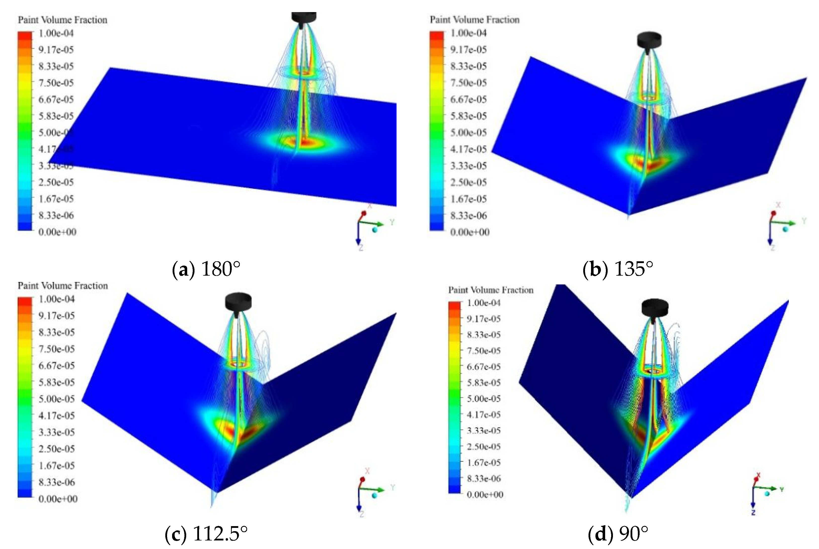
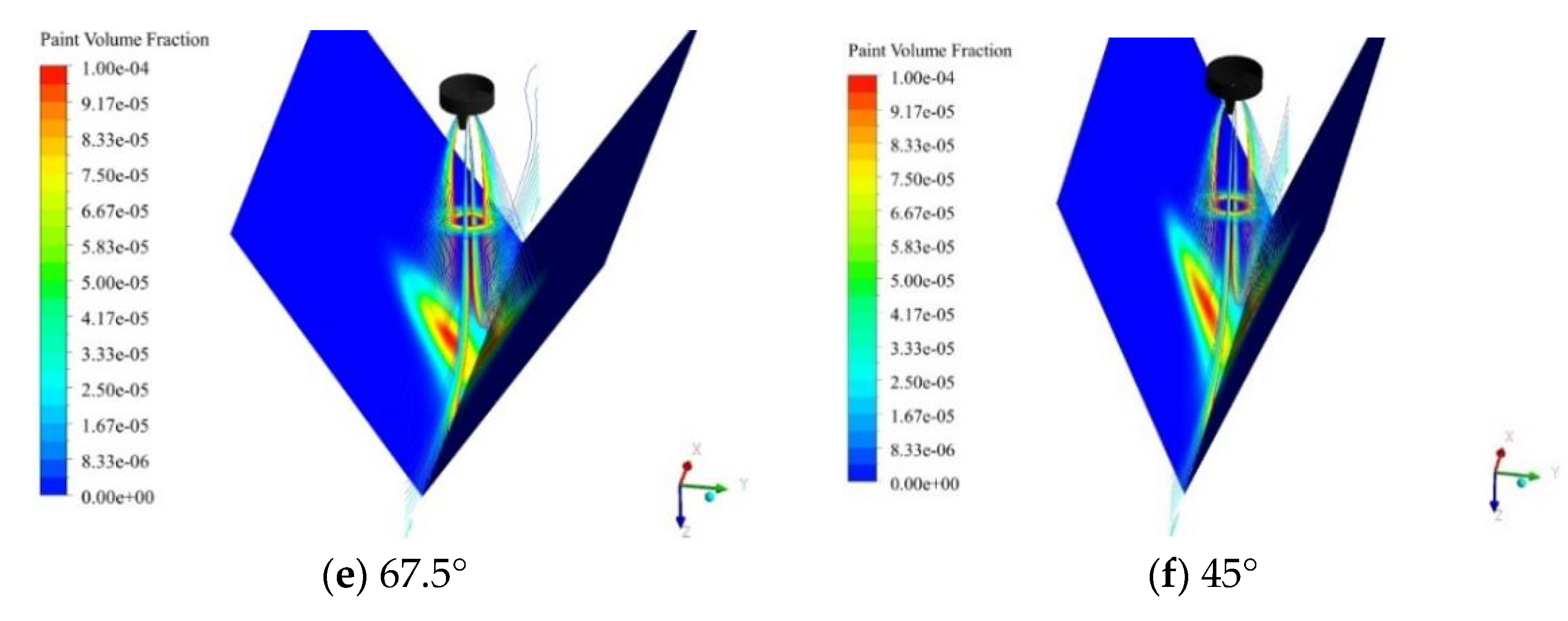
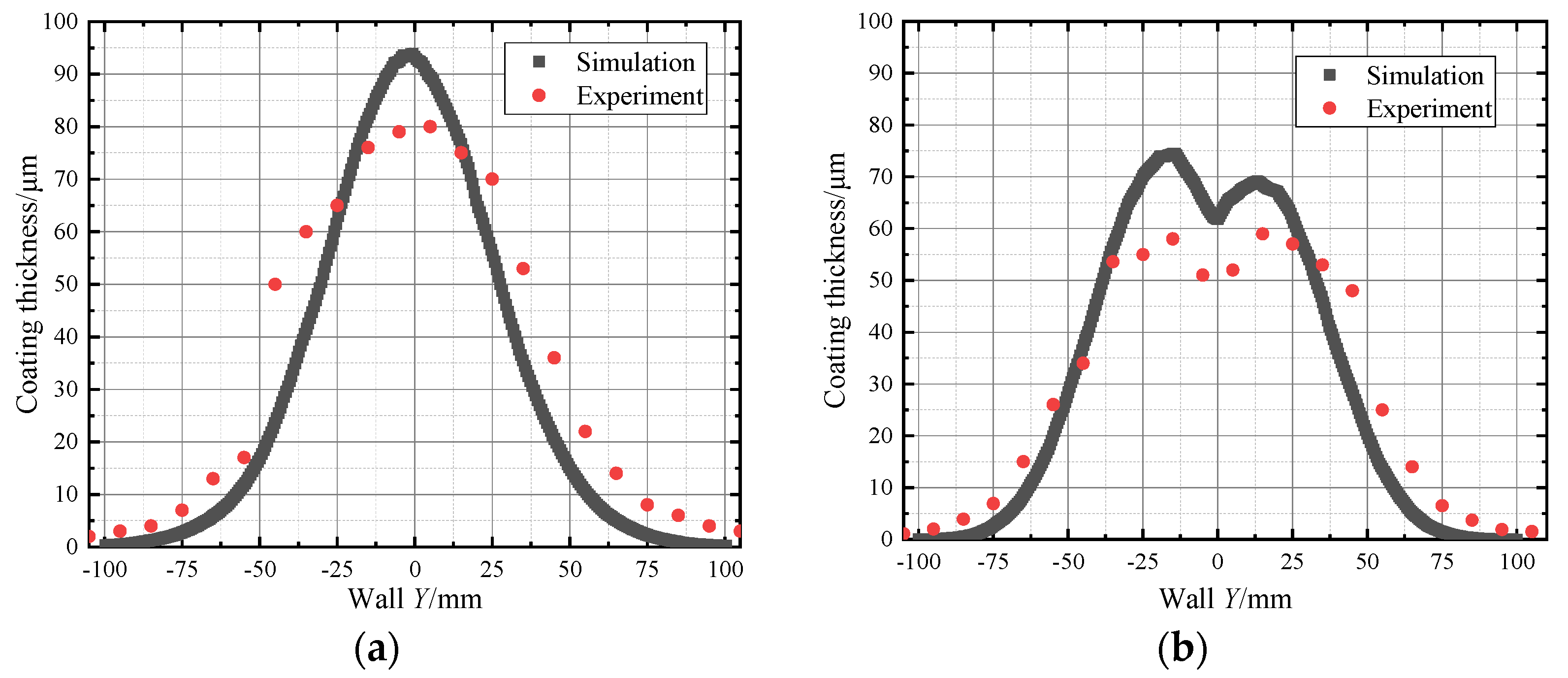
The numerical simulation results show that the coating thickness distribution was noticeably different for V-shaped surfaces with different angles. The coating thickness of the 180° V-shaped surface was in a single-peak distribution, where the central film was the thickest and gradually thinned outwards until disappearing. When the V-shaped surface with an angle less than 180° was sprayed, the coating thickness distribution of the V-shaped surface presented a double-peak distribution. As the V-shaped angle decreased, the peak thickness decreased, the peak position shifted to both sides, and the peak thickness widened.
(2)
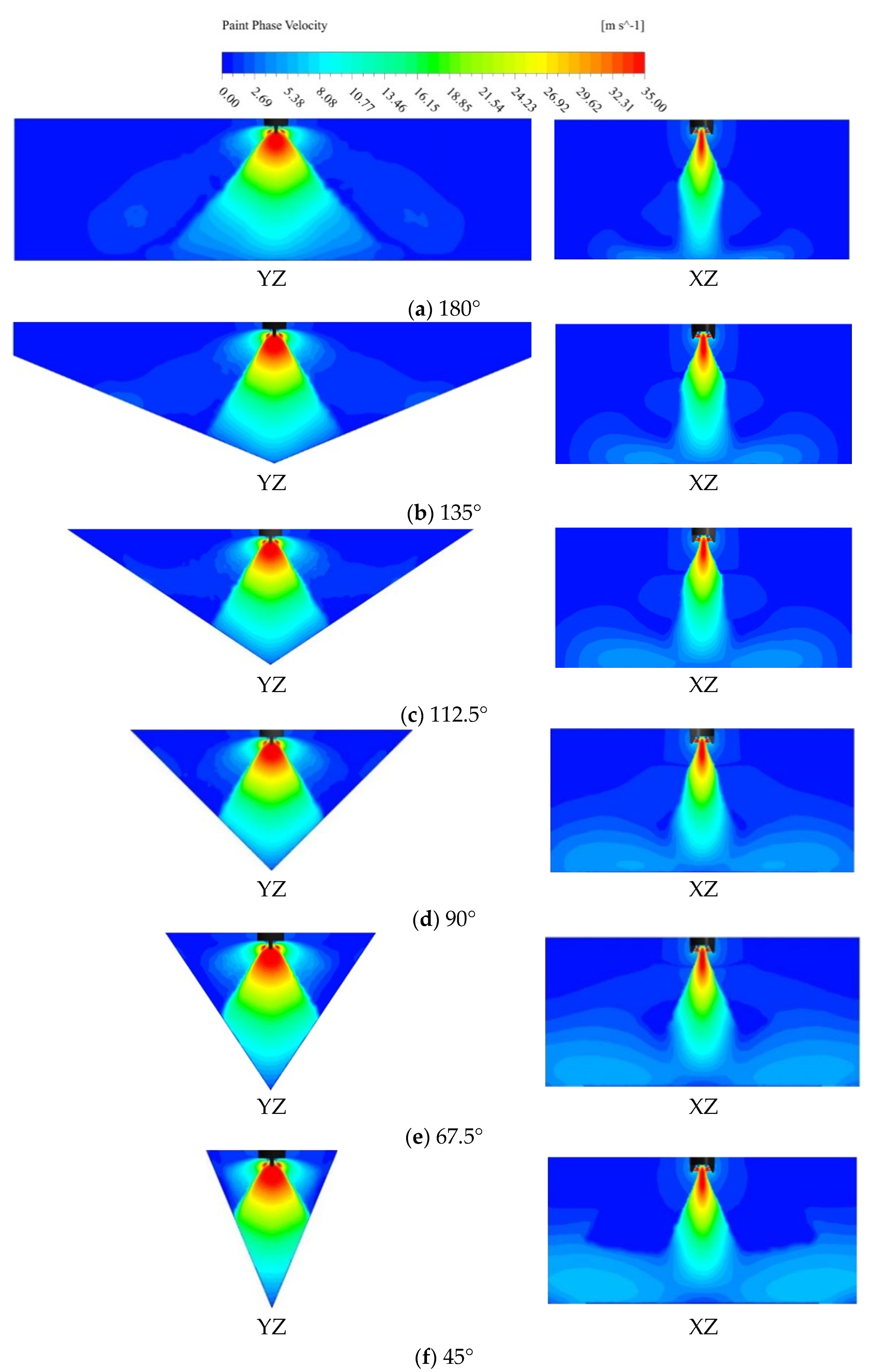
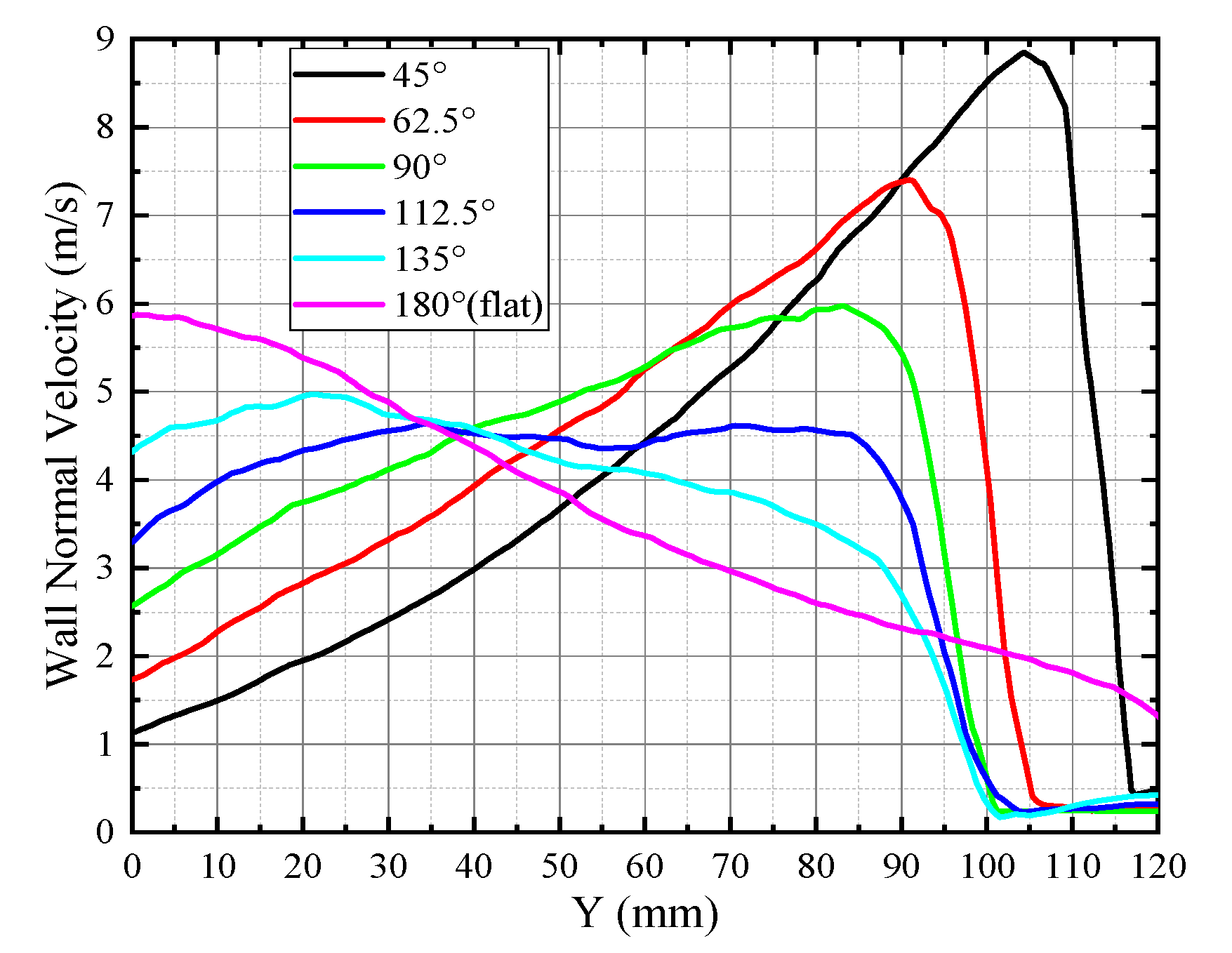
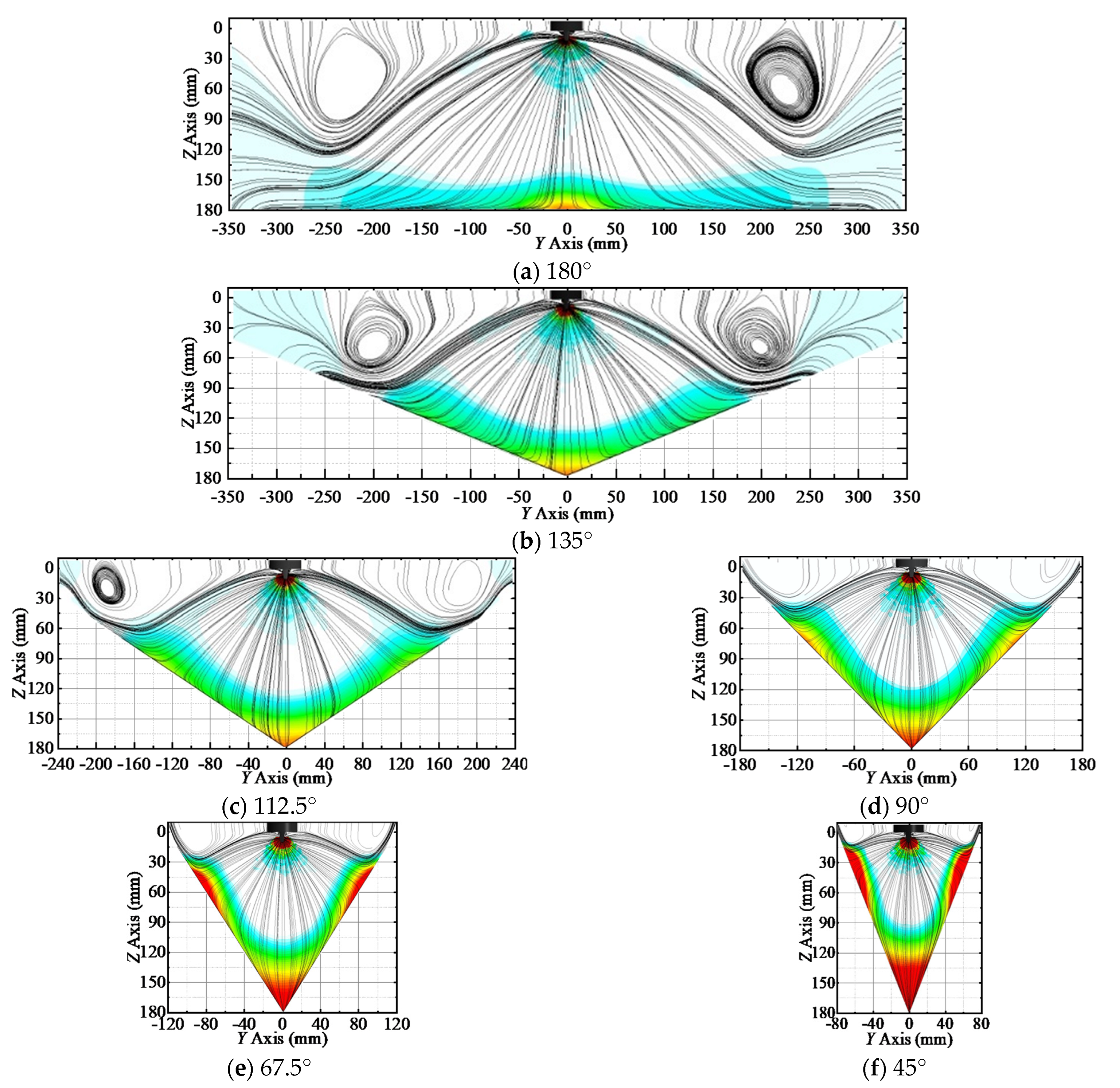
The coating thickness distribution of painting V-shaped surfaces with different angles differed because the velocity distribution of the near-wall flow field was different. Numerical simulation results show that the maximum of near-wall normal velocity when painting a 180° V-shaped surface was located at the center. As the V-shaped surface angle decreased, the normal velocity near the center of the wall constantly decreased, while the position of the maximum normal velocity gradually shifted outward. Since the coating thickness was proportional to the normal velocity perpendicular to the wall, the distribution law of the coating thickness occurred as described above.
(3)
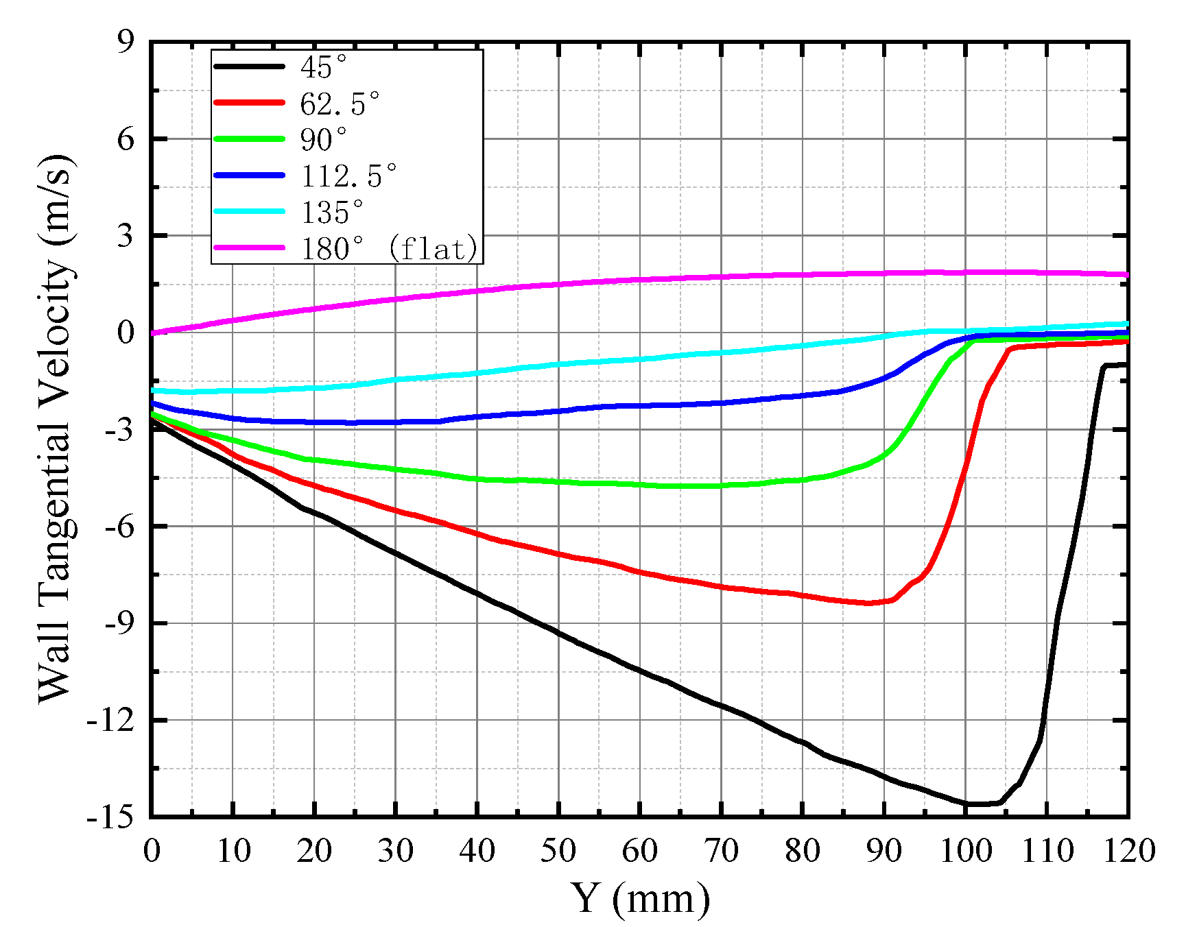
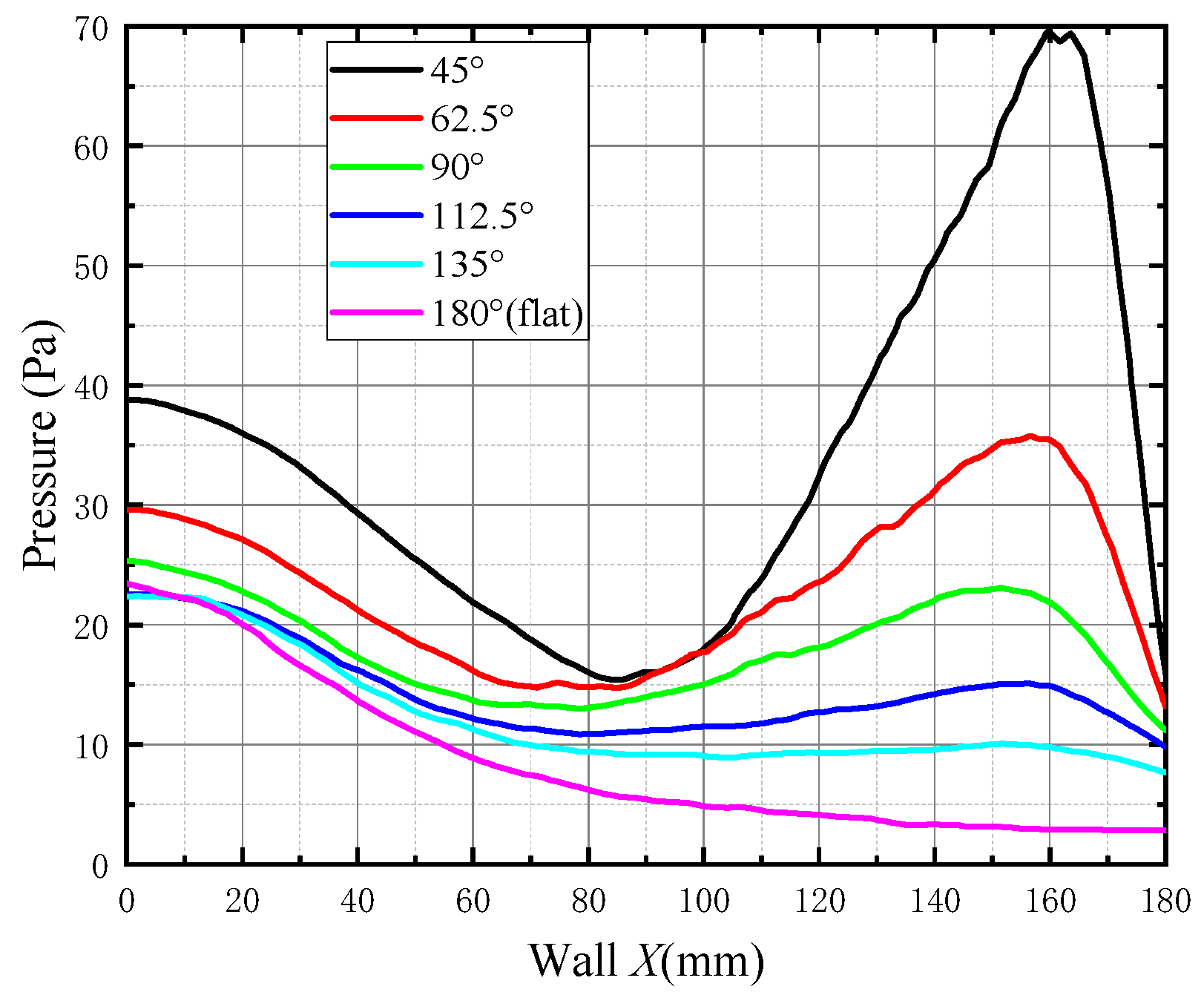
One reason for the different velocity distributions of the flow field in the near-wall region of painting V-shaped surface with different angles was the jet development mechanisms and geometric characteristics effect. As a kind of jet, the spray showed an increasingly smaller velocity and an increasingly wider distribution through development. The spray expansion degree on both sides became smaller, and the velocity increased as the V-shaped angle decreased. At the same time, the angle between the velocity vector of the fluid on both sides and the normal direction of the wall surface became smaller, causing the normal velocity perpendicular to the wall to increase. Secondly, the wall pressure distribution varied depending on the different angles of the V-shaped surface that was sprayed, leading to the change of near-wall velocity direction. When the V-shaped angle decreased, the central pressure peak increased, resulting in a greater resistance to liquid movement and the lower center velocity. In addition, the peak values of eccentric pressures formed on both sides of the wall became higher, causing the near-wall fluid to move toward the center. Thus, the near-wall fluid was confined between the center pressure peak and eccentric pressure peak, resulting in the paint’s spraying deposits between several pressure peaks on the V-shaped surface. Therefore, the coating thickness of the V-shaped surface with the angle less than 180° presented a double-peak distribution.
This work provides a theoretical basis for improving the quality of painting V-shaped surfaces, improving the spraying efficiency, and saving on the coating cost. However, due to the complexity of turbulence in spray flow and the multiplicity of factors affecting film formation, the effects of coating physicochemical properties and surfaces with greater complexity on film-formation characteristics remain to be discussed in the future.

Author Contributions

Conceptualization, S.C. and W.C.; methodology, Y.C.; software, S.Z.; validation, S.C. and W.C.; formal analysis, S.C. and W.C.; investigation, S.Z.; resources, S.C.; data curation, W.C.; writing—original draft preparation, S.C. and Z.W.; writing—review and editing, Y.C. and W.C.; supervision, J.J.; project administration, S.C. and W.C.; funding acquisition, Y.C. and J.J. All authors have read and agreed to the published version of the manuscript.

Funding

This project is supported by the National Natural Science Foundation of China (Grant No. 51475469), the Science and Technology Research Program of Chongqing Municipal Education Commission (Grant No. KJZD-M201912901 and KJZD-K202012903) and the State Key Laboratory of NBC Protection for Civilian (Grant No. SKLNBC2020-09).

Institutional Review Board Statement

Not applicable.

Informed Consent Statement

Not applicable.

Data Availability Statement

Not applicable.

Conflicts of Interest

The authors declare no conflict of interest.

References

  1. Zeng, Y.; Zhang, Y.K.; He, J.X.; Zhou, H.; Zhang, C.W.; Zheng, L. Prediction model of coating growth rate for varid dip-angle spraying based on Gaussian Sum model. Math. Probl. Eng. 2016, 2016, 9369047. [Google Scholar] [CrossRef] [Green Version]
  2. Park, K.; Jeon, D. Optimization of Tool Path Pitch of Spray Painting Robots for Automotive Painting Quality. Int. J. Control. Autom. 2018, 16, 2832–2838. [Google Scholar] [CrossRef]
  3. Chen, W.; Li, X.; Ge, H.L.; Wang, L.; Zhang, Y.H. Trajectory Planning for Spray Painting Robot Based on Point Cloud Slicing Technique. Electronics 2020, 9, 908. [Google Scholar] [CrossRef]
  4. Chen, W.; Liu, J.J.; Tang, Y.; Huan, J.; Liu, H. Trajectory Optimization of Spray Painting Robot for Complex Curved Surface Based on Exponential Mean Bezier Method. Math. Probl. Eng. 2017, 2017, 4259869. [Google Scholar] [CrossRef] [Green Version]
  5. Chen, W.Z.; Chen, Y.; Zhang, W.M.; He, S.W.; Li, B.; Jiang, J.Z. Paint thickness simulation for robotic painting of curved surfaces based on Euler–Euler approach. J. Braz. Soc. Mech. Sci. 2019, 41, 199. [Google Scholar] [CrossRef]
  6. Chen, W.Z.; Chen, Y.; Zhang, W.M.; He, S.W.; Li, B.; Jiang, J.Z. Numerical simulation for dynamic air spray painting of arc surfaces. J. ZheJiang Univ.-Sci. A 2018, 52, 2406–2413. [Google Scholar]
  7. Chen, Y.; Hu, J.; Zhang, G.; Chen, W.Z.; Pan, H.W.; Lou, B.W. Research on Characteristics of Paint Deposition on Spherical Surface. J. Hunan Univ. Nat. Sci. 2019, 542, 012024. [Google Scholar] [CrossRef] [Green Version]
  8. Liu, D.M. Trajectory Planning and Simulation of Dip Angle Spraying Based on Horns Surface. Master’s Thesis, Jiangsu University, Jiangsu, China, 2019. [Google Scholar]
  9. Chen, Y.; Chen, W.Z.; Chen, K.; Shao, J.Y.; Zhang, W.M. Trajectory Generation for Inner V-Shaped Surface. Appl. Mech. Mater. 2013, 380–384, 681–685. [Google Scholar] [CrossRef]
  10. Zeng, Y.; Gong, J.; Xu, N.; Wu, N.L.; Wang, F.Y.; Zhao, S.T. Tool trajectory optimization of spray painting robot for horns surface. J. Zhejiang Univ.-Sci. A 2014, 48, 791–798. [Google Scholar]
  11. Zhou, Y.Z.; Ma, S.M.; Li, A.P.; Yang, L.S. Path Planning for Spray Painting Robot of Horns Surfaces in Ship Manufacturing. In Proceedings of the 2019 3rd International Conference on Manufacturing Technologies (ICMT 2019), San Francisco, CA, USA, 4–7 January 2019. [Google Scholar]
  12. Magnini, M.; Pulvirenti, B.; Thome, J.R. Characterization of the velocity fields generated by flow initialization in the CFD simulation of multiphase flows. Appl. Math. Model. 2016, 40, 6811–6830. [Google Scholar] [CrossRef] [Green Version]
  13. Wang, Y.A.; Xie, X.P.; Lu, X.H. Design of a double-nozzle air spray gun and numerical research in the interference spray flow field. Coatings 2020, 10, 475. [Google Scholar] [CrossRef]
  14. Li, W.T.; Qian, L.J.; Song, S.B.; Zhong, X.K. Numerical study on the influence of shaping air holes on atomization performance in pneumatic atomizers. Coatings 2019, 9, 410. [Google Scholar] [CrossRef] [Green Version]
  15. Ye, Q.Y.; Pulli, K. Numerical and experimental investigation on the spray coating process using a pneumatic atomizer: Influences of operating conditions and target geometries. Coatings 2017, 7, 13. [Google Scholar] [CrossRef] [Green Version]
  16. Zuzio, D.; Estivalèzes, J. An improved multiscale Eulerian–Lagrangian method for simulation of atomization process. Comput. Fluids. 2018, 176, 285–301. [Google Scholar] [CrossRef] [Green Version]
  17. Ye, Q.; Shen, B.; Tiedje, O.; Bauernhansl, T.; Domnick, J. Numerical and experimental study of spray coating using air-assisted high pressure atomizers. At. Sprays 2015, 25, 643–656. [Google Scholar] [CrossRef] [Green Version]
  18. Liu, H.Q.; Liu, A.H.; Fan, S.D.; Wei, W. Erosion Influence and Protection of Ice-Water Two Phase Flow Pipe. Surf. Technol. 2019, 48, 109–116. [Google Scholar]
  19. Zhang, S.Z.; Mao, W.; Zhen, J.H.; Li, C.L. Research Progress of Coating Thickness Distribution Model by Electrostatic Spraying. Surf. Technol. 2019, 48, 291–297. [Google Scholar]
  20. Wang, F.F.; Li, W.Y.; Yu, M. Prediction of critical velocity in cold spraying based on numerically calculated steady maximum equivalent plastic strain. China Surf. Eng. 2012, 25, 96–100. [Google Scholar]
  21. Ye, Q.Y. Analysis of droplet impingement of different atomizers used in spray coating processes. J. Coat. Technol. Res. 2017, 14, 467–476. [Google Scholar] [CrossRef]
  22. Xie, X.P.; Wang, Y.N. Research on distribution properties of coating film thickness from air spraying gun-based on numerical simulation. Coatings 2019, 9, 721. [Google Scholar] [CrossRef] [Green Version]
  23. Fogliati, M.; Fontana, D.; Garbero, M.; Vanni, M.; Baldi, G. CFD Simulation of Paint Deposition In an Air Spray Process. J. Coat. Technol. Res. 2006, 3, 117–125. [Google Scholar] [CrossRef]
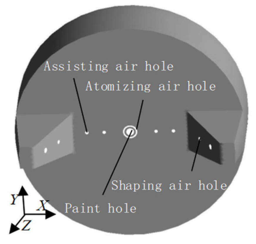
Figure 1. Geometric model of air cap of spray gun.
Coatings 12 00658 g001
Figure 2. Coordinate system of 3D air cap geometry. (a) Y–Z plane. (b) X–Z plane.
Coatings 12 00658 g002
Figure 3. Sketches of painting patterns. (a) Perpendicular mode. (b) Parallel mode.
Coatings 12 00658 g003
Figure 4. Meshing.
Figure 4. Meshing.
Coatings 12 00658 g004
Figure 5. Contours for displaying distribution of coating thickness and paint-volume fraction. (a) 180° V-shaped surface; (b) 135° V-shaped surface; (c) 112.5° V-shaped surface; (d) 135° V-shaped surface; (e) 135° V-shaped surface; (f) 45° V-shaped surface.
Coatings 12 00658 g005aCoatings 12 00658 g005b
Figure 6. Sketch of wall coordinate. (a) Y–Z plane. (b) X–Z plane.
Coatings 12 00658 g006
Figure 7. Coating thickness distribution. (a) Y–Z plane. (b) X–Z plane.
Coatings 12 00658 g007
Figure 8. Contours of air velocity.
Coatings 12 00658 g008
Figure 9. Contours of paint velocity.
Coatings 12 00658 g009
Figure 10. Comparison of the near-wall normal velocity.
Coatings 12 00658 g010
Figure 11. Comparison of the near-wall tangential velocity.
Coatings 12 00658 g011
Figure 12. Pressure and streamline.
Coatings 12 00658 g012
Figure 13. Pressure distribution.
Coatings 12 00658 g013
Figure 14. Static spraying experiments. (a) 180° V-shaped surface. (b) 90° V-shaped surface.
Coatings 12 00658 g014
Figure 15. Comparison between simulation results and experimental results. (a) Painting 180° V-shaped surface. (b) Painting 90° V-shaped surface.
Coatings 12 00658 g015
Table 1. Aperture parameters of the air cap.
ParametersDiameter of Paint HoleDiameter of Atomizing Air HoleOuter Diameter of Atomizing Air HoleDiameter of Assisting Air HoleDiameter of Small Shaping Air HoleDiameter of Large Shaping Air Hole
Diameter/mm1.11.62.00.50.60.8
Table 2. The corresponding attribute parameters in numerical simulation.
Physical ParametersAir PhasePaint Phase
Density (kg/m3)1.231.2 × 103
Viscosity (kg/m∙s)1.7894 × 10−59.686 × 10−2
Surface tension coefficient (N/m)——2.87194 × 10−2
Publisher’s Note: MDPI stays neutral with regard to jurisdictional claims in published maps and institutional affiliations.

