1. Introduction
Over the past few years, the demand for offshore concrete construction has increased significantly. It has been widely implemented in civil and military terminals, offshore airports, offshore wind power plants, sea lighthouses, offshore oil construction, etc. Concrete structures are exposed to both physical and chemical degradation offshore. The main chemical deterioration is caused by seawater constituents on cement hydration products and the crystallization of salts in the concrete [
1,
2]. Water waves, floating objects, freezing, and thawing cause physical erosion [
3,
4]. To ensure the durability of concrete structures, protective coating layers are applied to increase resistance to those negative factors.
A variety of internal and external stimuli can induce coating adhesion failure. Mechanical stress, environment-induced thermal stress, and corrosion are the most typical reasons for adhesion failure [
5]. The delamination or blistering of the marine concrete structure is the main phenomenon leading to the deterioration of the coating layer. The blistering of the coating layer can occur during the application of the coating material due to the air trap. The coating layer can also deteriorate after application due to external factors [
6,
7]. The wall thinning of the coating layer and debonding of the coating layer from the concrete reduce protection capability, and in time, detection and repair procedures must be carried out [
8,
9]. Mainly ultrasonic methods are used for the monitoring of the structural health of coated concrete structures. Despite many achievements in ultrasonic nondestructive testing, the precise detection of defects relies on the experience and theoretical knowledge of the technicians.
The frequency of the ultrasonic beam plays an important role in the precise determination of the bonding delamination and the thickness of the coating layer [
10,
11]. The thin coating layer requires high frequencies; on the other hand, the ultrasonic losses increase with frequency [
12,
13]. Recently, a method for detecting metallic layer debonding using the resonant frequency of reflected ultrasonic echo waves has been implemented [
14]. The limitation of the resonance-based bonding estimation is that the wavelength of the waveform is required to be an integer multiple of the thickness, which is almost impossible in the case of coating layers.
The acoustic mismatch between the coating material and concrete depends on the bonding strength between layers. The acoustic difference reaches its peak when the coating material is disbanded from the concrete specimen due to the presence of air between the two layers [
15,
16]. The phase of the reflected waveform can be used to estimate the acoustic properties of the material of the multilayered materials [
17,
18,
19]. Additionally, Wang et al. [
20] used several parameters of the chirp and experimentally found that the phase of the waveform was the most sensitive one among wave parameters. However, in the experiment, the air-coupled thermal wave radar imaging method was used to detect defects in the laminates. The wave phase can be estimated using the Hilbert transform, which is an efficient method with low computational requirements [
21,
22]. It allows the implementation of analytic waveforms to calculate the wave phase [
23].
Recently, time-frequency analysis based on short-time Fourier transform of the waveform has been used to detect debonding of coating layers [
24,
25]. A major limitation of the short-time Fourier approach is its fixed-length time window, and accurate time and frequency resolution cannot be obtained simultaneously. On the other hand, continuous wavelet transform can provide a finer scale resolution compared to short-time Fourier spectral analysis. Furthermore, CWT (Continuous Wavelet Transform) is not limited to the fixed-length window function, and it yields a better resolution of the high-frequency components and also of the transient waveform [
26,
27,
28,
29]. Many other researchers have found that CWT has better resolution transient waveforms compared to STFT (Short-Time Fourier Transform) [
30,
31,
32].
The ultrasonic detection of defects between two layers based on multiple parameters of the waveform and underwater inspection of coating layers increase the complexity of ultrasonic detection. In this study, a DNN (deep neural network) was implemented to ensure automatic detection of the debonded coating layer based on waveform parameters. Moreover, the DNN has been successfully implemented in many other fields and has shown good results in classification-related problems [
33,
34,
35]. In the DNN’s processes, hyperparameters and their values critically impact its performance and prediction accuracy. Because of a large number of hyperparameter values, manually adjusting hypermeters is a time-consuming process and requires a great deal of experience [
36,
37,
38].
Until now, there have been few studies on the detection of the debonded section of the coating layer applied to the concrete structure in water immersion tests. Recent research has been based on the following methods: high-frequency wave echo decomposition [
39], reflection coefficient theory [
40,
41], pulse-velocity-based methods [
42,
43], wave attenuation [
44,
45], the data fusion technique [
46], the multifrequency method [
47], and time-based parameters [
48].
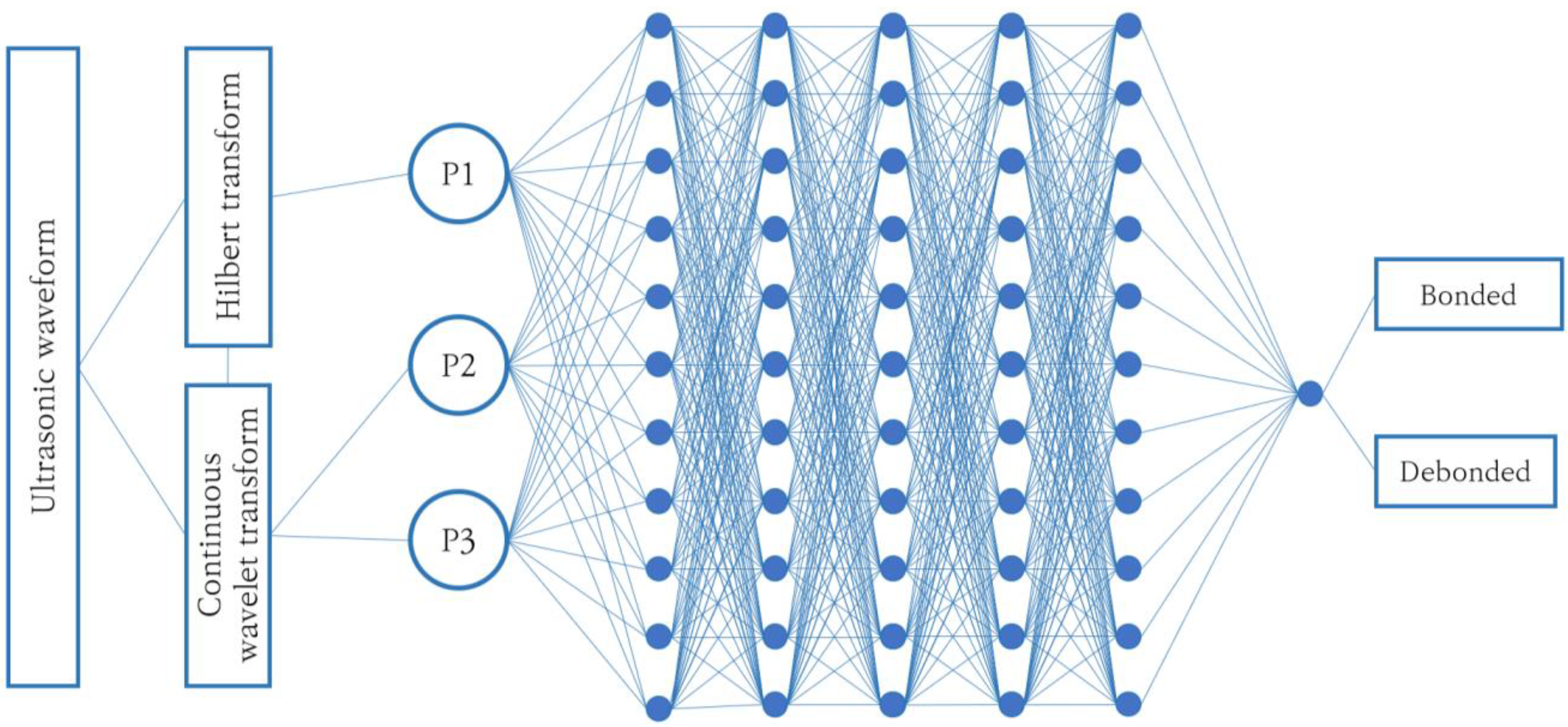
In this present research, the DNN-based automatic detection method for underwater coated concrete specimens is described. A novelty of the current research is the relative parameters of the waveform used to detect coated layer debonding, which eliminate the effect of variable parameters of reflected echoes on delamination detection. Both relative and absolute parameters of the ultrasonic waveform, such as TOF, instantaneous center frequency, and the phase of the echoes were calculated using the CWT and HT of the waveform and used to train the DNN. The hyperparameters of the DNN were tuned by a Bayesian optimization method, and the results showed 100% accuracy in detection of debonded layers.
4. Experimental Results
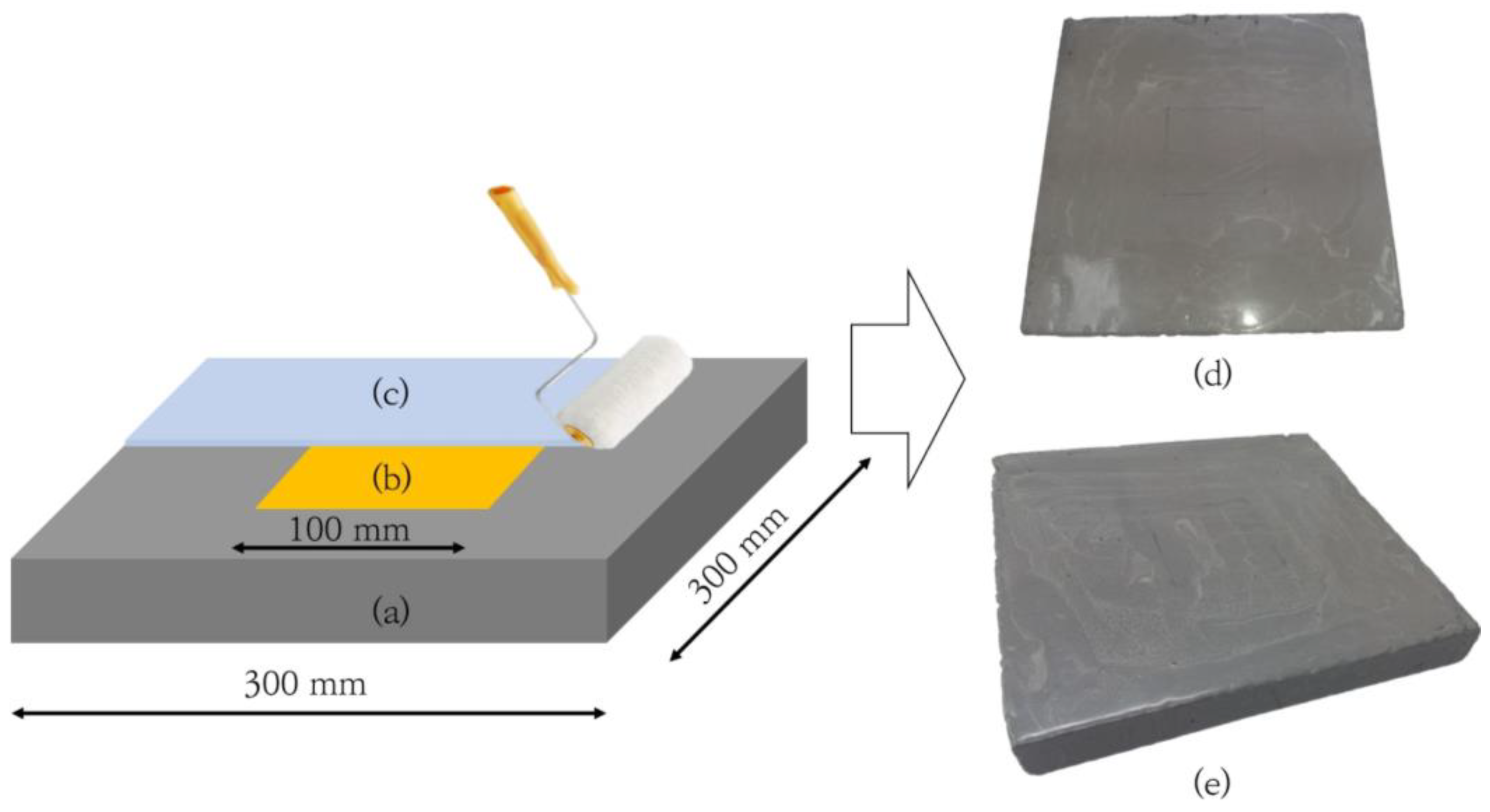
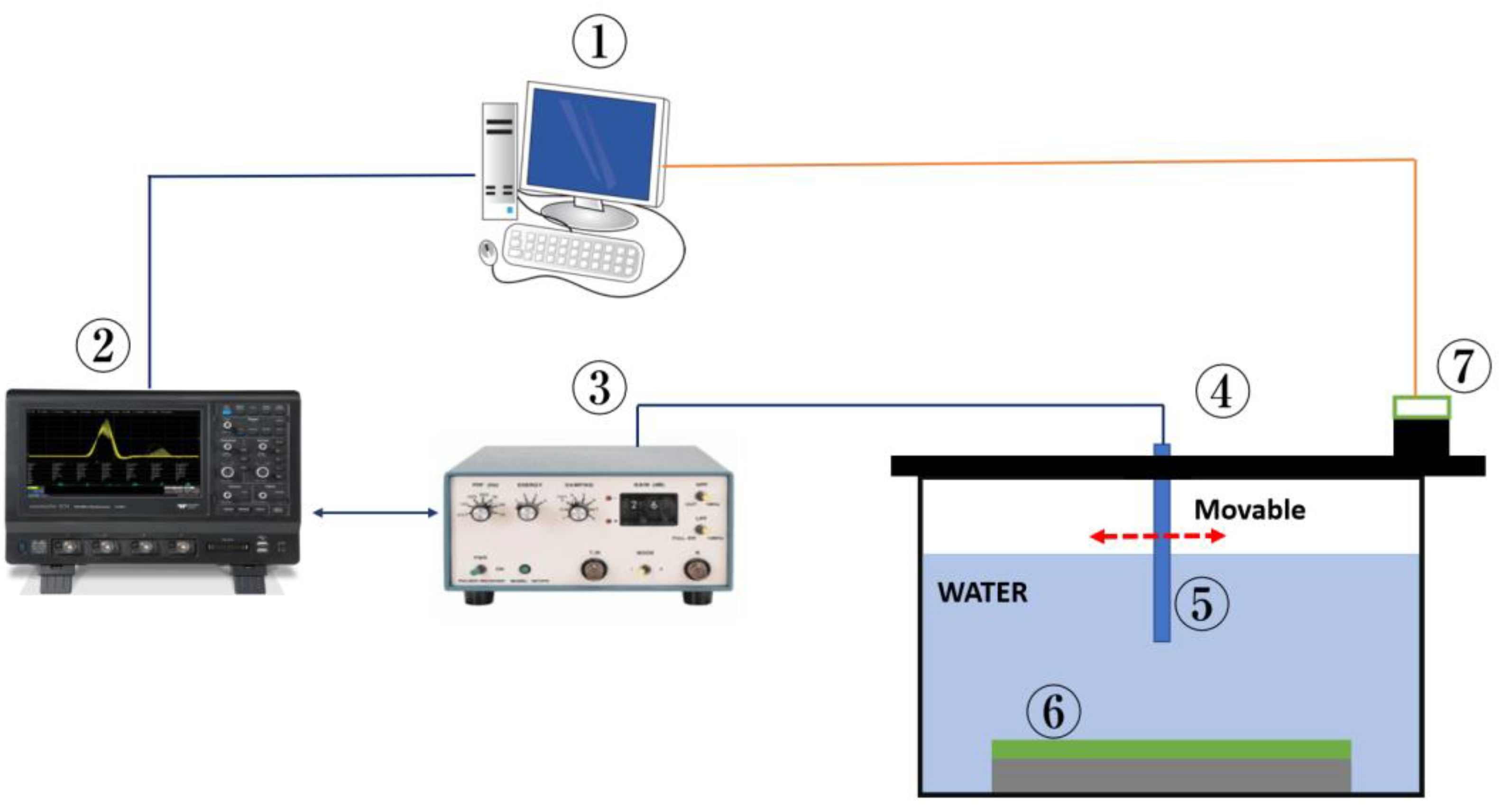
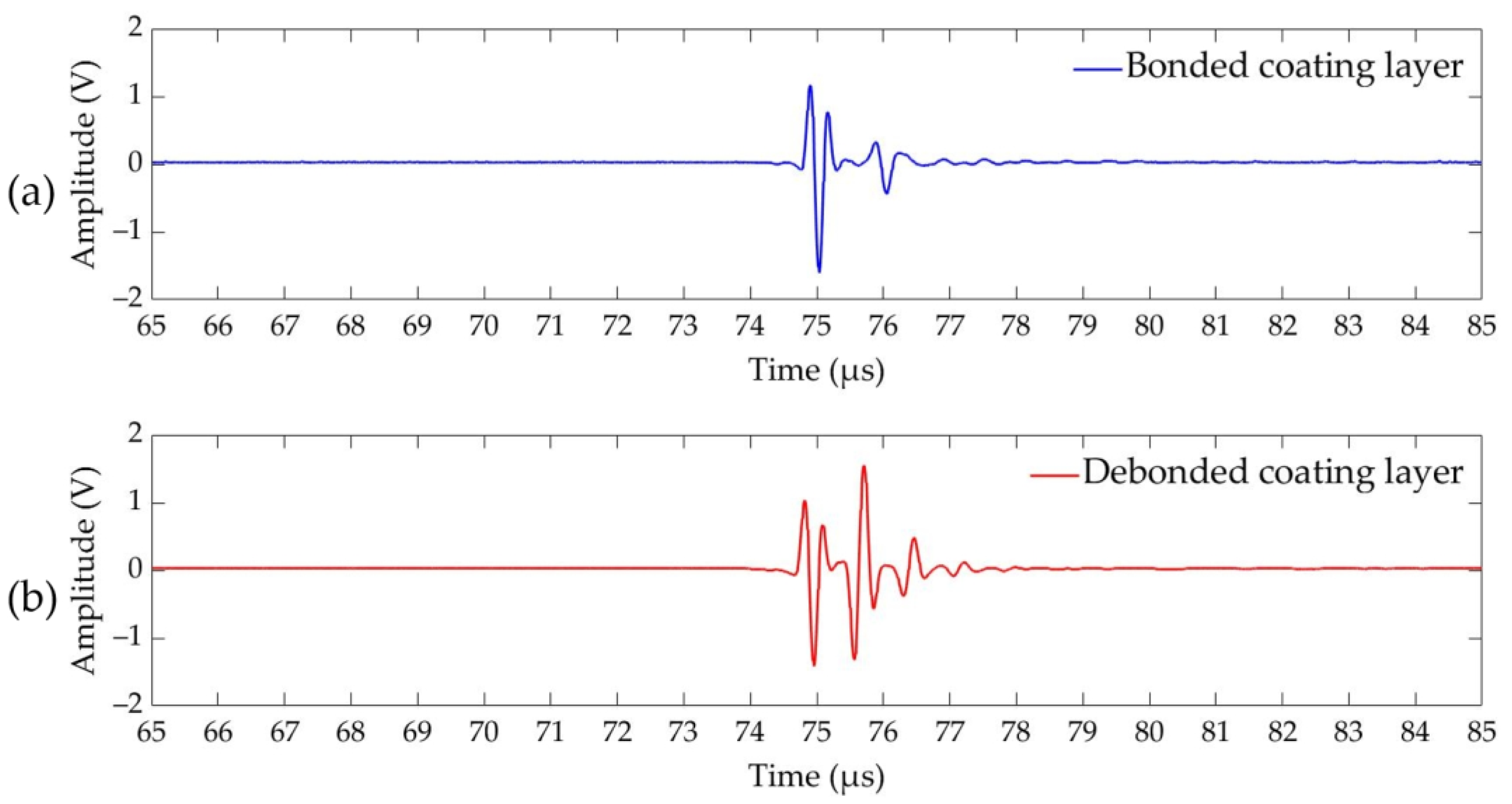
The fabricated specimens were immersed in the water immersion test stand. An automated scanning system was used to obtain pulse-echo waveforms from the surface of the specimen. During ultrasound scanning of the specimen, the probe was shifted by 5 mm in each step, and corresponding coordinates of the probe were saved together with their accompanying reflected echo waveforms. Due to the manufacturing method of the concrete blocks, the surface roughness was not perfectly uniform. Therefore, the times of flight (TOFs) of the first echoes from the surface of specimen, A0, is not expected to be the same, due to the slight change in the distance between the transducer tip and the coated concrete surface. Additionally, the thickness of the applied coating layer is affected by the surface quality, and there may be slight variation in the coating layer thickness depending on the coating process. The ultrasonic scanning equipment allows quick scan of the surface of specimen and acquiring waveforms. The ultrasonic test results are shown in
Figure 4a for the bonded coating and in
Figure 4b for the debonded portion of the coating layer. From an initial glance at the obtained time domain waveforms, it is very difficult to find the distinguishable parameter.
As shown in
Figure 4, the TOFs of the reflected echo from the surface of the coating layer (A0) and the wall of the coating layer (A1) were not identical. These differences in the TOF are due to the surface finishing of the concrete and the application of the coating, which does not produce a uniform layer thickness.
The CWT was applied to all waveforms to evaluate the ultrasound’s characteristics.
Figure 5a shows the waveform from the debonded section of the specimen, and its time–frequency representation is shown in
Figure 5b. The local concentration in the contour plot corresponds to the maximum energy, and it defines the instantaneous center frequency of the echo. The time–frequency plot allows the instantaneous center frequency of each echo to be calculated separately. The corresponding center frequencies of the first and the second reflection echoes were calculated, and the values are assigned, correspondingly, as “CF of A0” and “CF of A1” in
Table 2. As we can see from the table, the instantaneous center frequencies of the A0 echoes, which were reflected from the surface of the coating layer, were close to the center frequency of the probe regardless of the bonding state of the coating layer. In fact, the values of the instantaneous center frequencies of the A0 echoes are related to the surface quality of the coating material. Whereas the second reflected echo (A1) arrives from the back wall of the debonding part, the waveform is scattered due to the interference between the coating layer and the concrete block. The center frequency of the A0 echo from the debonded layer was equal to 3.58 MHz, whereas the CF of A1 was 3.12 MHz.
Another important parameter is the phase of the reflected echo, so in this research, the phases of the waveforms at the local peaks of the CWT were calculated. The advantage of the calculation of the phase in a single point is the reduction in the computational effort. The waveform can also be analyzed in the time-phase domain, but this method does not immediately highlight the features of the waveform. The Hilbert transform, together with CWT parameters (as described in Equation (7)), was used to calculate the phase of the reflected echoes. The phases of the echoes at the local peaks of CWT are shown in
Table 2, and they are denoted as the “Phase of A0” for echo A0 and the “Phase of A1” for echo A1. The values of the phases at the local peak of the CWT are similar for A0 echoes, regardless of the bonding state of the coating layer. This is because the phase of the A0 echo depends only on the acoustic impedance difference between the coating layer and the water. On the other hand, the values of the phase of the A1 echoes are different, depending on the bonding condition of the coating layer. The phase of the reflected echo from the backwall of the coating layer is reversed due to the fact that the debonded space between the water and the concrete will be occupied with either water or air. Water and air have a lower acoustic impedance than concrete and coating materials, resulting in negative reflection. HT and CWT (Equation (7)) were used to calculate the phase of reflected echoes.
Table 2 displays the phase values of the echoes, showing that the phase of the A1 echo was shifted by 180 degrees for the debonded case compared to A0 based on the numerical estimates.
The local peaks of the projection of the CWT magnitude correspond to the TOF waveform. The TOF of the reflected echo was derived by projecting the CWT onto the time domain, as shown in
Figure 5c. Estimated values of the TOF of the wave echoes of A0 and A1 are shown in
Table 2, and they are denoted, respectively, as “TOF of A0” and “TOF of A1”. Therefore, if the wave propagation speed in the coating layer is known, the thickness can be estimated. Alternatively, the TOF of reflected echoes can be calculated manually from the time domain waveform (
Figure 4); however, doing so is a time-consuming process. Fast inspection is crucial when inspecting large specimens. Based on the TOFs of echoes, the layer’s thickness is estimated to be 0.86 mm. Additionally, another advantage of evaluation of the TOF of the wave echoes based on the local peaks of the CWT magnitude is the capability to obtain precise results under the low signal-to-noise ratios, which is very convenient in order to detect coating layer wall flattening. As the walls of the coating layer become thinner, the echoes are superimposed in the time domain, and in those cases, the evaluation of TOF based on the CWT scalogram becomes necessary.
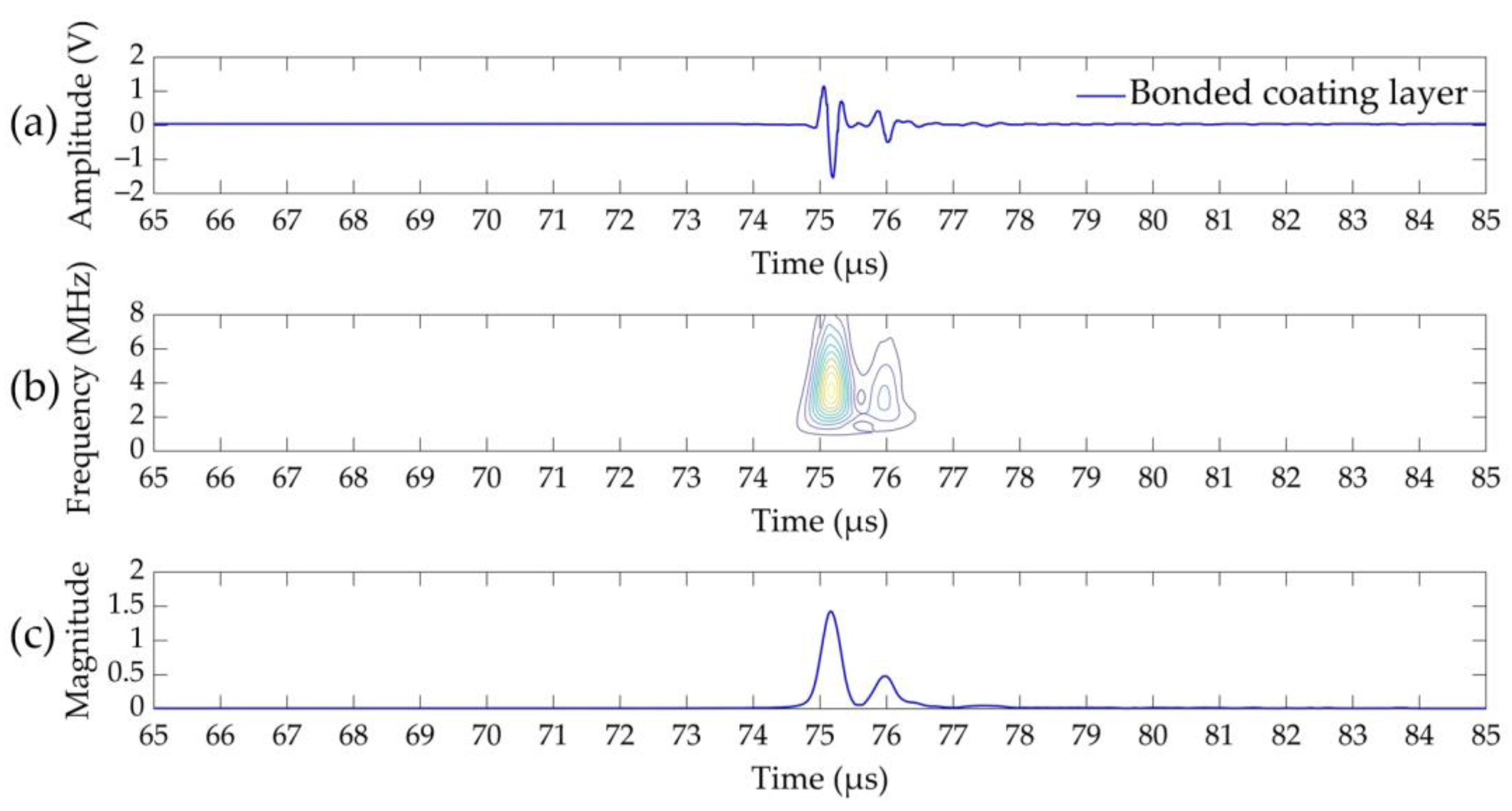
The bonded section was also inspected in the same way, and the corresponding waveform and its CWT are shown in
Figure 6. The time-domain waveform is shown
Figure 6a,b shows the time-frequency domain representation of the waveform. Similarly, for the debonded case, the instantaneous center frequencies of the reflected echoes for the bonding layer were estimated using
Figure 6b, and the results are shown in
Table 2. In addition, the echo phase of the local peak of the CWT magnitude of the bonded coating material was also calculated using the HT and CWT wave parameters. The calculated values are also listed in
Table 2. Correspondingly, the TOF of the A0 and A1 echoes were calculated based on the local peaks of the projection of the CWT scale graph to the time domain as shown in
Figure 6c, and the values can be seen in
Table 2. The thickness of the coating layer was measured using the TOF, and it was found to be 0.97 mm thick.
Additionally, the TOF of the echo from the surface A0 and that from the backwall of the coating layer A1 were slightly different. The TOF of the A0 echo is related to the distance between the ultrasonic probe and the coating layer surface, and the nonuniform thickness of the concrete affects the TOF of A0 echoes. In addition, the difference in the TOF of the A1 echo can be explained by a slightly different coating material thickness due to the application method. Additionally, the bonded coating layer has a lower CWT magnitude of A1 echo compared to the debonded layer due to the wave energy transformation from coating to the concrete. In the debonded layer, the trapped air between the coating layer and the concrete causes the reflection of nearly all ultrasonic energy, thus increasing the CWT magnitude of A1.
Based on the results of the experiments, it is very difficult to establish a certain threshold value for classifying the state of the coating layer. In this study, we introduce three more relative parameters to classify the bonding state of the coating material. The first parameter is the ratio of the local peaks of the CWT magnitude of the echoes reflected from the back wall and the surface of the coating material. The ratio of the local peaks of the CWT magnitude determines the attenuation rate of wave energy in the coating material itself. The second parameter is the phase difference between the A1 and A0 echoes, since, as described above, the phase of the echo depends on the bonding condition between the two media. Last but not least, the ratio of the instantaneous center frequencies of the A0 and A1 echoes is a unitless parameter that compares the scattering of the reflected echoes from the surface and the back wall of the coating layer. The calculated relative parameters for both bonded and detached layer are shown in
Table 3 below.
In real applications, the local density of the coating material can vary due to the presence of inhomogeneous porosity in the coating layer, and the water quality can also change due to environmental influences. It is difficult to set threshold values for each parameter, since the values may change depending on the instrument settings, water condition, and coating layer porosity. In this study, three relative parameters of the echoes were selected, and these values were used as the input of the DNN. The details of the DNN are described in the next section below.
6. Discussion
In this research, we used waveform parameters to the classify bonding state of the coating material. In particular, the ratio of local peaks on the CWT magnitude, which is proportional to the echo amplitude, is a relative parameter to compare the attenuation rates in different coating layers. As shown in
Figure 5 and
Figure 6, the CWT magnitude of the A1 echo for bonded coating layers was lower compared to the debonded coating layers. Due to the wave energy transmission between the coating layer and concrete, bonded layers attenuate at a faster rate than debonded layers [
87,
88].
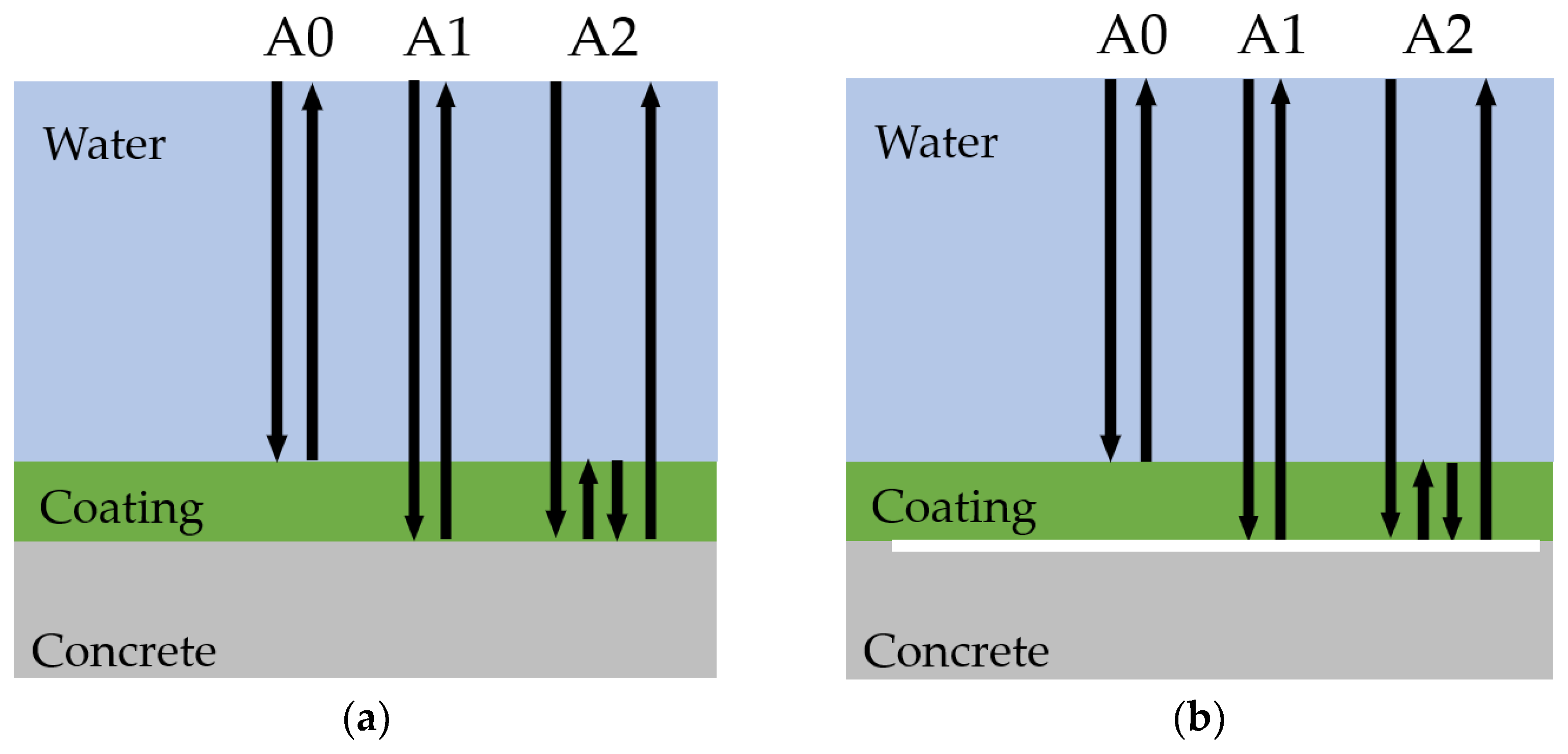
The phase of the echoes computed by CWT and HT of the waveform confirms the theoretically derived derivation described in
Section 2. The phase of the echo from the surface and the back wall concrete was equal when the coating layer was bonded to the concrete substrate. As a matter of fact, both acoustic energy reflection coefficients in the bonded case were positive [
89]. In the case of delamination, the space between the coating and the concrete is occupied with water or air, leading to a negative reflection coefficient (as seen in
Table 1), and the phase of the second echo is reversed by 180° [
90]. The method would be accurate even if seawater instead of tap water were used during the experiments, since the acoustic impedance difference between tap water and seawater is not significant. These values are 1.4 × 10
6 kg/(m
2s) and 1.53 × 10
6 kg/(m
2s), respectively.
The waveform parameters calculated in
Table 2 depend on instrument setting, water condition, and coating layer thickness [
91]. For instance, variations in water salinity affect the amplitude of reflected echoes because of acoustic impedance effects. A probe’s frequency and bandwidth parameters can also affect the received waveform. As frequency increases, the attenuation rates increase, and the narrow band parameters can result in echoes overlapping. In this study, three relative parameters of the wave echoes were used to classify the bonding condition of the coating and to eliminate the effect of variable parameters of the experiment. As can be seen from
Table 3, the CWT ratio was greater in the bonded layer, which indicates a higher attenuation rate. Another relative parameter is the phase difference between echoes, which is zero when the coating layer is bonded. A delaminated layer has a phase difference of 180° [
92,
93,
94]. Additionally, the CF ratio of reflected echoes was used as a parameter to classify the bonding state. A higher CF ratio between A1 and A0 indicates more scattering of wave energy between the coating layer and concrete substrate [
95,
96].
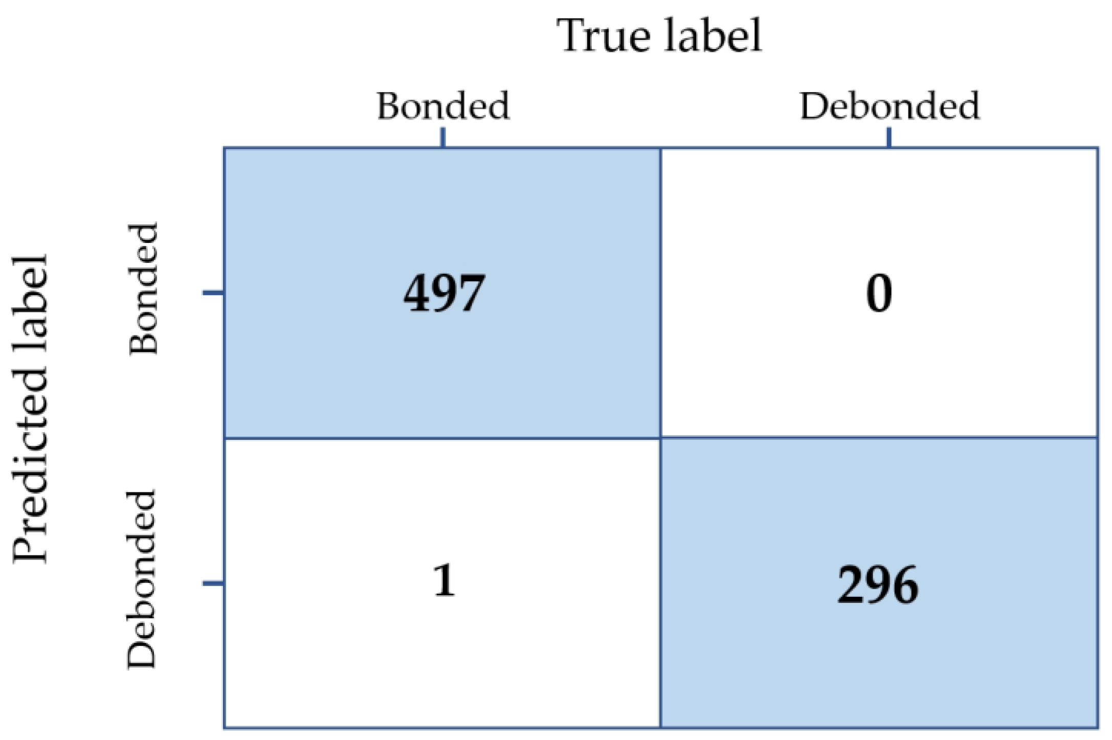
Both the accuracy and the precision of the prediction are hyperparameters of the DNN effects. Using DNN with optimally tuned hyperparameters, we were able to automatically classify the bonding state of coating layers. Three relative parameters of the reflected echo were sensitive to delamination, allowing 100% accuracy in detecting debonding.


 ,
, 


