Article

Vibration Reduction Characteristics and Vibration Control of Aviation Hydraulic Pipeline by Hard Coating

School of Mechanical Engineering and Automation, University of Science and Technology Liaoning, Anshan 114051, China
*
Author to whom correspondence should be addressed.
Coatings 2022, 12(6), 775; https://doi.org/10.3390/coatings12060775
Submission received: 10 May 2022 / Revised: 31 May 2022 / Accepted: 31 May 2022 / Published: 4 June 2022

Abstract

:
Aviation hydraulic pipelines are an important channel for power transmission in aviation hydraulic systems. Due to long-term exposure to complex vibration environments, hydraulic pipeline systems are susceptible to accumulated fatigue damage failure, which poses a great threat to aircraft safety and reliability. At present, there are only passive ways to reduce hydraulic pipeline vibration, such as adding vibration isolators and damping bearings. These methods have a poor vibration damping effect and are not safe. In this study, a hard coating was used as a new vibration reduction method for aviation hydraulic pipelines to reduce the damage caused by vibrations. For this purpose, three different hard-coating materials were optimally selected, and model creation, finite element analysis, and experimental research were carried out to study the vibration responses of hard-coated aviation hydraulic pipelines under the actual working conditions of an aircraft. The optimal solution was obtained through orthogonal experiments. The vibration reduction rate of the aviation hydraulic pipelines could reach 20.33% under the constant-frequency excitation of the low-pressure rotor of the engine, and the vibration reduction rate under the constant-frequency excitation of the high-pressure rotor could reach 26.60%. The rationality of the model was verified, and it was proven that the hard coating could meet the demands of vibration control in practical engineering and provide a reference for the vibration analysis and vibration control design of aviation hydraulic piping systems.

1. Introduction

The early world aviation powers did not pay enough attention to external pipelines [1], resulting in frequent engine pipeline system ruptures, oil leakages, and oil leakage failures [2]. During the test run of an engine, many failures are caused by vibration problems [3], such as the resonance of the piping system and excessive dynamic stress [4], which affect the entire development cycle of the engine. If an engine is considered the heart of an aircraft [5], the pipeline is equivalent to the cardiovascular system of the engine, and its structural integrity has an important impact on the safe and reliable operation of the engine and on the aircraft structure [6]. According to research, the failure of hydraulic system pipelines causes aircraft crashes and accounts for 36.7% of all aircraft component failures [7]. Strong vibrations occur due to the foundation excitation of the external frame and the fluid pulsation excitation of the pump source due to fluid–structure coupling, among other reasons, and they cause pipeline failure. Therefore, the vibration of an aviation hydraulic pipeline system is an engineering problem that urgently needs to be solved.
There are a number of methods for passive vibration isolation. Bakre et al. [8] found that installing a friction device between a pipeline system and bracket increases the energy consumption of the system and suppresses vibrations. Kobayashi et al. [9] found through experimental research that the energy dissipation of a pipeline support device has a significant effect on reducing the amplitude of the entire system and developed two differentiated damping supports. Li Xin [10] reduced the vibrations of a piping system by optimizing the layout of clamps. Liu Fanghua [11] carried out a finite element simulation of a hydraulic vibratory hammer and proposed multiple methods, such as multicloth clamps and vibration damping by an accumulator, to reduce vibrations. However, indirect methods for reducing the vibration of hydraulic pipelines are ineffective, time-consuming, and unsafe. With the addition of Fe, Cr, and Al, the hardness, compressive properties, thermodynamic properties, vibration-damping properties, and other mechanical properties of the Fe–Cr–Al matrix alloy will be improved [12]. Yu et al. [13] studied the damping performance of coatings prepared by plasma spraying and determined that the resonance frequency of the hard-coated cantilever beam structure shifted to a high frequency, and the resonance amplitude decreased. Chen Yugang and Shen Pengfei [14,15] explored the mechanism and law of hard coating for blisk vibration suppression and life extension.
The friction of particles inside a coating can effectively dissipate external energy [16], thereby reducing structural vibrations after coating and inhibiting fatigue caused by vibrations [17]. The use of hard coatings for vibration reduction has become a new research direction [18,19], and studies have been conducted on the vibration reduction of aeroengine hydraulic pipelines based on hard coatings. Pipeline vibrations can be effectively reduced by changing the characteristics of the pipelines [20,21]. In this study, three preferred coating materials were applied to an aviation hydraulic pipeline system for vibration reduction. A dynamic analysis of the pipeline system was performed before and after the hard coating was applied, a finite element model was established, and experimental verification was carried out. The effects of different hard-coating materials and thicknesses on the vibration characteristics and damping effects of pipelines with different materials were explored.

2. Materials and Methods

2.1. Selection and Preparation of Experimental Materials

Surface engineering can be used to prepare a functional thin surface layer with a performance superior to that of the matrix material itself. Its thickness ranges from micrometres to millimetres, and it can achieve high-temperature resistance, wear resistance, corrosion resistance, and vibration and noise reduction. According to aerospace standards, aviation hydraulic pipelines made of 6061T6 aluminium alloy, TA18 titanium alloy, and Nitronic40 (XM-10) S21900 stainless steel were selected as the spraying substrate. The three preferred coating powders and their vibration-damping properties were as follows:
(1)
YSZ (8%Y2O3-ZrO2) coatings. In engineering practice, when YSZ powder hits the surface of the substrate in a molten state through atmospheric plasma spraying, it spreads and forms lamellae. With the continuous accumulation of the lamellar structure, a hard YSZ coating with interlayer pores, spherical pores, and microcracks is formed, which has excellent thermal shock resistance. The YSZ coating could significantly improve the damping performance of the substrate, though the substrate temperature and evaporative beam can affect the damping performance by changing the microstructure of the coating [22]. An agglomerated YSZ nanopowder (Beijing Chemical Company, Beijing, China) produced by a company in Beijing was selected as the raw material for preparing the coating.
(2)
YSZ–PTFE composite coating. PTFE is a high-molecular-weight polymer with an excellent low loss tangent and stable dielectric constant. In engineering practice, PTFE is filled with ceramic fillers to change its material properties and can be used as a damping material to gradually attenuate the incoming vibration energy, thereby realising vibration reduction and noise reduction. The PTFE composite material was coated on the surface of rolling bearings to test its main mechanical properties and damping, and the results showed that PTFE can be used in the field of vibration reduction [23]. PTFE powder produced by a chemical company in Fuxin (Fuxin Chemical Company, Fuxin, China) was selected.
(3)
Al–Cu–Fe–Cr quasicrystal coatings (Beijing Chemical Company, Beijing, China). These are a kind of intermetallic compound with a structure between periodic and disordered, and they have the properties of high hardness, a low friction coefficient, and low thermal conductivity. Because of their inherently high brittleness, they are usually prepared on the surface of substrates as a thermal barrier coating. In view of the special properties of quasicrystalline coatings, Professor Chungen Zhou used low-pressure plasma spraying to prepare Al–Cu–Fe–Cr quasicrystalline coatings on Ti alloy substrates and found that they have vibration-damping properties. The selected quasicrystalline powder material was an Al–Cu–Fe–Cr ternary quasicrystalline alloy.

2.2. Experimental Design

The pipeline was sprayed with Oerlikon Metco9MC plasma-spraying equipment (Oerlikon Metco Surface Technology, Shanghai, China). To study the vibration reduction effect of different hard-coating materials on different pipeline materials with different thicknesses, the type of hard-coating material, coating thickness, and pipeline material were considered as different factors, and each factor was set to three levels. Table 1 shows the design of the 3-level 3-factor orthogonal test Table L9(33). The design of the orthogonal experimental spraying scheme is shown in Table 2.

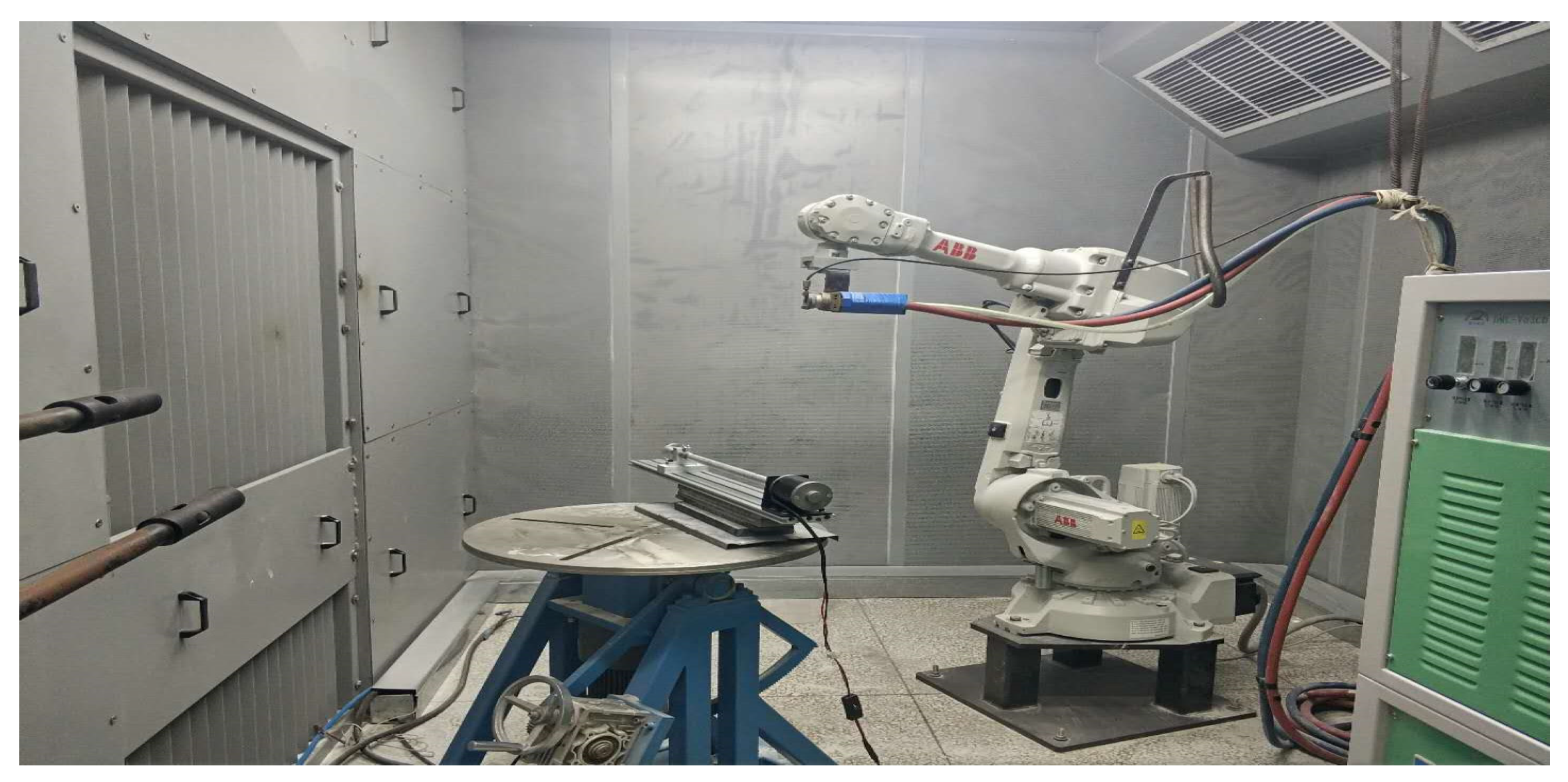
2.3. Atmospheric Plasma-Spraying Equipment and Hard-Coating Preparation Process

Oerlikon Metco 9MC atmospheric plasma-spraying equipment (Oerlikon Metco Surface Technology, Shanghai, China) was used, which is composed of a control cabinet, an air-supply system, a chiller, a powder feeder, and a spray gun. The pipeline substrate pretreated by a GP-1 dry sandblasting machine was fixed on the experimental bench by a homemade rotatable clamp. The coating powder was sent to the powder supply port, and the powder was heated to a molten state at a high temperature and sprayed onto the surface of the substrate by a PLC programmable robot arm (IRB52 (Oerlikon Metco Surface Technology, Shanghai, China)) for condensation deposition. Straight hydraulic pipeline specimens hard-coated with three different materials at different thicknesses were prepared by spraying equipment. Deposition parameters are shown in Table 3. A diagram of the preparation device is shown in Figure 1.
First, we used a GP-1 dry sandblasting machine to spray a transition layer of Al2O3 on the outside of the pipeline. Then, we applied the coating with Oerlikon Metco 9MC atmospheric plasma-spraying equipment. When a particle beam at a certain temperature hits the surface of the substrate at a high speed, due to the acceleration of the particles colliding with the surface of the pipeline, a large amount of pressure is exerted, which deforms the particles into a flat shape. During the deformation process, the particles rapidly cool down and shrink, and finally combine closely with the surface of the pipeline. The sprayed material continuously hits the surface of the pipeline, and a large number of particles repeat the process of collision–impact–deformation–cooling and solidification–shrinkage. Many particles adhere to the surface of the pipe to form a coating.
The functions of each component of the atmospheric plasma-spraying equipment are as follows:
(1)
Control cabinet. This is mainly used to control the various gases, such as argon, hydrogen, and powder gas, and the spray-gun cooling water transmitted during the spraying process. Various parameters in the spraying process can be adjusted in real time to protect the normal operation of the equipment.
(2)
Spray gun. This is composed of a gas pipeline, a powder feeder, a cathode, and an anode. The spray gun can form a high-temperature and fast atmospheric plasma arc.
(3)
Powder feeder. This controls the storage, supply, delivery rate, and particle size of the coating powder.
(4)
Robotic arm. An IRB52 industrial robotic arm produced by ABB in Switzerland was used.

3. Finite Element Model of a Hard-Coated Straight Aviation Hydraulic Pipe

3.1. Establishment of the Finite Element Model

(1)
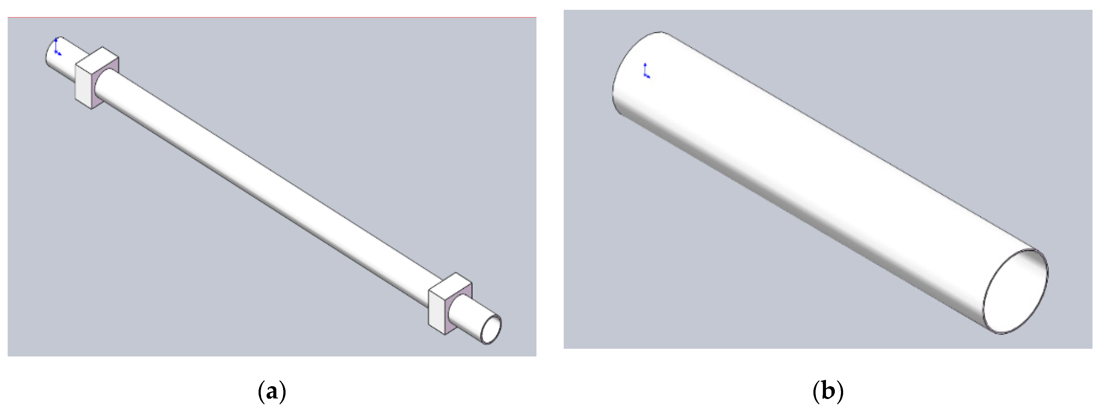
Simplified modelling of a straight pipe
The parametric modelling of the straight aviation hydraulic pipe was carried out using SolidWorks. On the vibrating test bench, it was necessary to fix and support the straight pipe with a clamp. In practical engineering, the assembly gap between the components complicates the connection relationship between the components in the model, and mechanical transmission is prone to errors. Therefore, the straight pipe model had to be simplified according to the principle of model simplification. The simplified model is shown in Figure 2a.
(2)
Simplified modelling of a hard coating
We used atmospheric plasma spraying to coat the aviation hydraulic pipeline with the three powders, which we regarded as a round tube of corresponding thickness for simplified calculations in reasonable circumstances, as shown in Figure 2b.

3.2. Material Parameters

The piping material parameters found in the literature are shown in Table 4. The hard-coating parameters are shown in Table 5.

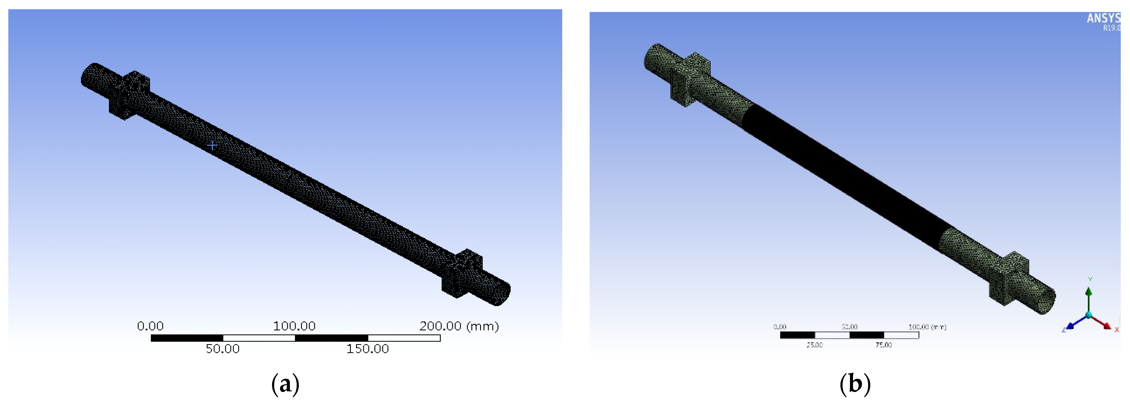
3.3. Mesh Segmentation

We imported the model into the modal module of ANSYS Workbench (version 2016) for modal analysis. The meshing tools in Workbench include static meshing, structural dynamics, and explicit dynamics tools. The mesh types are divided into hexahedral, tetrahedral, pyramidal, and prismatic meshes, as shown in Figure 3. The uncoated model in this paper had 93,729 nodes, 49,610 meshes, and a mesh size of 2 mm. The uncoated model meshing is shown in Figure 4a. The number of model nodes coated with a hard coating was 3,445,847, the number of meshes was 660,830, the mesh size of the pipeline was 2 mm, and the mesh size of the coating was 0.2 mm. The coated model meshing is shown in Figure 4b.

4. Finite Element Analysis of the Hard-Coated Straight Aviation Hydraulic Pipe

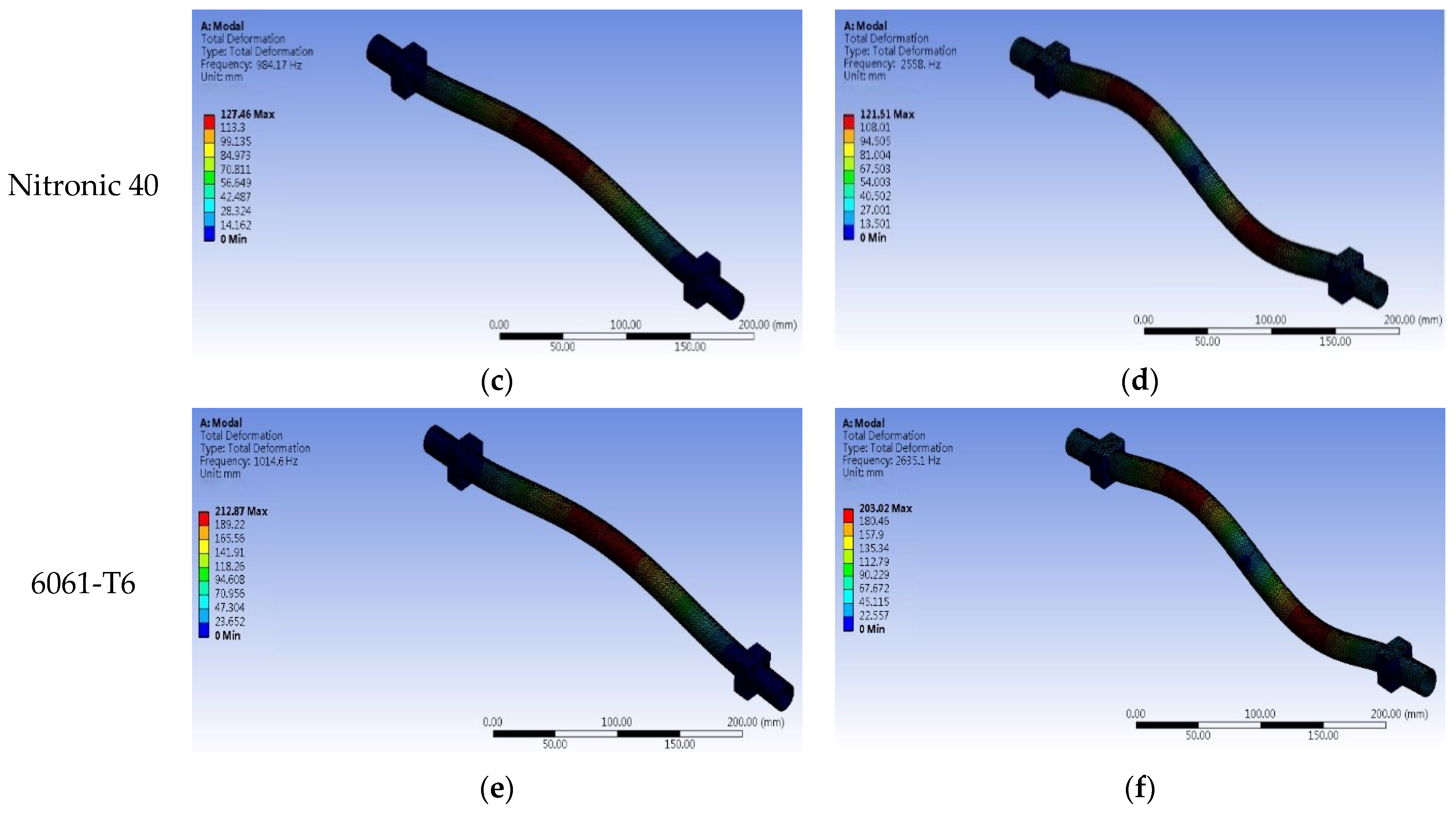
4.1. Modal Analysis of the Hard-Coated Straight Aviation Hydraulic Pipe

The effects of the hard-coating material and thickness on the natural frequency of the model and the displacement of the main mode shape were explored. The 3D model of the aeroengine hydraulic pipeline established in SolidWorks was imported into the modal module of ANSYS Workbench. A modal analysis of the straight aviation hydraulic pipe before and after coating was carried out to obtain the first 10 natural frequencies and the displacement of the main mode shape. Several modal vibration diagrams are presented in Figure 5. The results are shown in Table 6, Table 7, Table 8 and Table 9. The main mode shape displacement comparison diagram is shown in Figure 6.
From Table 6 and Table 7, it can be concluded that for TA18 titanium alloy pipes coated with the YSZ–PTFE and YSZ coatings, the low-order natural frequencies decreased gradually with increasing coating thickness, and the high-order natural frequencies increased gradually with increasing coating thickness. With the increase in the thickness of the hard coating, the offset of the natural frequency of the straight aviation hydraulic pipe gradually increased. Its first-order natural frequency offset could reach a maximum of 7.5%, which meets the requirements of preventing resonance by changing the natural frequency of the straight aviation hydraulic pipe.
As seen from Figure 6, all orders of magnitude of the maximum displacement variable after the application of the hard coating decreased to varying degrees with increasing coating thickness. The YSZ–PTFE coating was most effective in reducing the deformation of the first three orders of magnitude of the main vibration pattern. The maximum deformation of the main vibration pattern of the aviation hydraulic pipeline decreased with increasing coating thickness. The simulation results show that the hard coating had a good suppression effect on the vibration of the straight aviation hydraulic pipeline. Similarly, the finite element simulation data for Nitronic40 stainless steel and 6061T6 aluminium alloy were consistent with the above conclusions.

4.2. Simulation-Based Harmonic Response Analysis of the Straight Aviation Hydraulic Pipe

The engines of ordinary civil airliners usually use turbofan jets. The rotational speeds of domestic Taihang engines are 16,200 and 13,000 r/min, and the CFM56-7B engines used in Boeing 737 series aircraft are 15,183 and 5380 r/min. In this paper, a commonly used engine was included as a reference. The excitation frequencies of the low-pressure and high-pressure rotors during normal operation were f1 = 5380/60 = 89.67 Hz and f2 = 16,200/60 = 270 Hz as the fixed frequency, and the acceleration amplitude was set to 2 g. Several fixed-frequency vibration response diagrams for the straight aviation hydraulic pipe before and after coating are shown in Figure 7 and Figure 8. Table 10 shows the vibration response results for constant-frequency excitation.
The acceleration responses in Figure 8 show that the fixed-frequency acceleration response of the low-pressure rotor was lower than that of the high-pressure rotor. Taking the 6061T6 aluminium alloy as an example, the acceleration response at the low-voltage frequency was 0.63 g, and the acceleration response at the high-pressure rotor excitation frequency was 6.10 g; the acceleration value increased by an order of magnitude. The fixed-frequency simulation experiment results in Table 10 show that for the high- and low-pressure rotors at a constant excitation frequency, the acceleration response values of the same pipeline after coating were lower than those before coating to different degrees.

5. Harmonic Response Analysis of the Straight Aviation Hydraulic Pipe Based on Experimental Testing

For the experiment, we adopted an electrodynamic vibration test system manufactured by Suzhou Dongling Vibration Instrument Co., Ltd. The electromagnetic vibrating table consists of a vibrating table, a power amplifier, a cooling system, and a controller. The vibrating table establishes a magnetic field in the table body through an excitation coil. The excitation coil is connected to a DC power supply to generate a high magnetic flux. As the coil is driven by the circulating AC power, the table top vibrates up and down, simulating the basic excitation of the pipeline system under working conditions. A lightweight sensor was arranged at the maximum displacement of the first-order main mode of the tested pipeline. The layout of the shaking-table test is shown in Figure 9.
The data acquisition and analysis system comprised an INV3060S 24-bit network-distributed acquisition instrument, produced by Beijing Dongfang Institute of Vibration and Noise Technology, and Coinv DASP V11 signal testing and analysis software, as shown in Figure 10. In this experiment, signal acquisition was accomplished by connecting the ICP acceleration sensor to data channel one of the acquisition instrument, and the sensor was fixed on the outer surface of the pipeline. The sensor parameters are shown in Table 11.

5.1. Experiment to Determine the Low-Pressure Fixed-Frequency Harmonic Response of Engine Double Rotors

The pipeline before and after the application of the hard coating was fixed on the vibration test bench, the acceleration sensor was pasted on the surface of the pipeline, and the vibration signal of the sensor was collected by the INV3062V 24-bit network-distributed acquisition instrument. The vibration response of the straight aviation hydraulic pipe before and after the application of the hard coating was analysed in the nonresonant state under basic excitation conditions. The set excitation frequency was the low-voltage rotor excitation frequency of 89.67 Hz, and the excitation force acceleration was 2 g. The vibration response of the straight aviation hydraulic pipe before and after hard coating application was obtained according to Table 2, which shows the vibration response test experiment table for the hard-coated aviation hydraulic pipeline. A few responses are presented in detail in Figure 11.

5.2. Experiment to Determine the High-Pressure Fixed-Frequency Harmonic Response of Engine Double Rotors

The excitation frequency was set to 270 Hz for the high-voltage rotor, and the acceleration of the excitation force was 2 g. The vibration response of the straight aviation hydraulic pipe before and after coating was obtained. A few responses are depicted in detail in Figure 12.

5.3. Analysis of Experimental Results

Analysis of Orthogonal Experimental Results of the Constant-Frequency Excitation of High- and Low-Voltage Rotors

In the orthogonal experiment involving the constant-frequency excitation of high- and low-pressure rotors, the vibration responses of the straight aviation hydraulic pipe under fixed-frequency simple harmonic excitation before and after coating were compared and analysed. The orthogonal experimental results are shown in Table 12 and Table 13.
Experiment R in Table 12 shows that the most influential factor for the vibration reduction of the aviation hydraulic pipeline under the constant-frequency excitation of the low-pressure rotor was the thickness of the coating (A); the second most influential factor was the hard-coating material (B); and the third most influential factor was the pipe material (C). According to the K value of factor A, the third-level thickness of 300 μm was the best; that is, the greater the thickness, the higher the vibration reduction rate. For factor B, the first-level YSZ–PTFE coating had the best vibration-damping effect. The third-level aluminium alloy pipe material outperformed the other two materials for factor C. The experiments showed that the coated aviation hydraulic pipelines experienced different degrees of vibration reduction. The optimal combination according to the orthogonal experiments was a stainless-steel piping system with a coating of no. 8 YSZ–PTFE and a coating thickness of 300 μm. The vibration reduction rate reached 20.33% under 89.67 Hz low-voltage fixed-frequency excitation.
Experiment R in Table 13 shows that the most influential factor for the vibration reduction of the aviation hydraulic pipeline under the constant-frequency excitation of the high-pressure rotor was the thickness of the coating (A); the second most influential factor was the hard-coating material (B); and the third most important factor was the pipeline material (C). According to the K value, the third-level thickness of 300 μm performed the best for factor (A); the first-level YSZ–PTFE coating had the best vibration reduction for factor (B); and for factor (C), the third-level 6061T6 aluminium alloy pipe material was the best. These results were consistent with the conclusions obtained for the low-voltage fixed-frequency excitation. The optimal combination according to the orthogonal experiments was a pipeline system composed of 304 stainless-steel coated with YSZ–PTFE at a coating thickness of 300 μm. The vibration reduction rate reached 26.60% under 270 Hz high-voltage constant-frequency excitation.

5.4. Comparison between Simulation Results and Experimental Test Results

To verify the accuracy of the finite element model, the simulation results were compared with the experimental results, and the error between the simulation and experimental values was calculated. The comparison results are shown in Table 14.
From Table 14, it can be concluded that the maximum error between the acceleration response value of the hard-coated straight aviation hydraulic pipe obtained by the finite element simulation and the experimental value was for the constant-frequency excitation of the no. 8 high-pressure rotor, and the error was 10.9%. The minimum error was obtained for the constant-frequency excitation of the no. 6 low-voltage rotor, and the error was 0.38%. Regarding the comparison of the overall results, the average error of the constant-frequency excitation of the high- and low-voltage rotors was below 5%, and the simulation conclusions were consistent with the experimental conclusions. It was determined that the straight aviation hydraulic pipe model used in the simulation calculation was reasonable and met the demands of engineering calculations.

6. Conclusions

In this paper, based on aviation hydraulic pipeline vibration theory and the method of combining simulations and experiments, three hard-coating materials were optimally selected and prepared to carry out simulation analysis and experimental research on the vibration characteristics and vibration reduction of aviation hydraulic pipelines. The main conclusions were as follows:
(1)
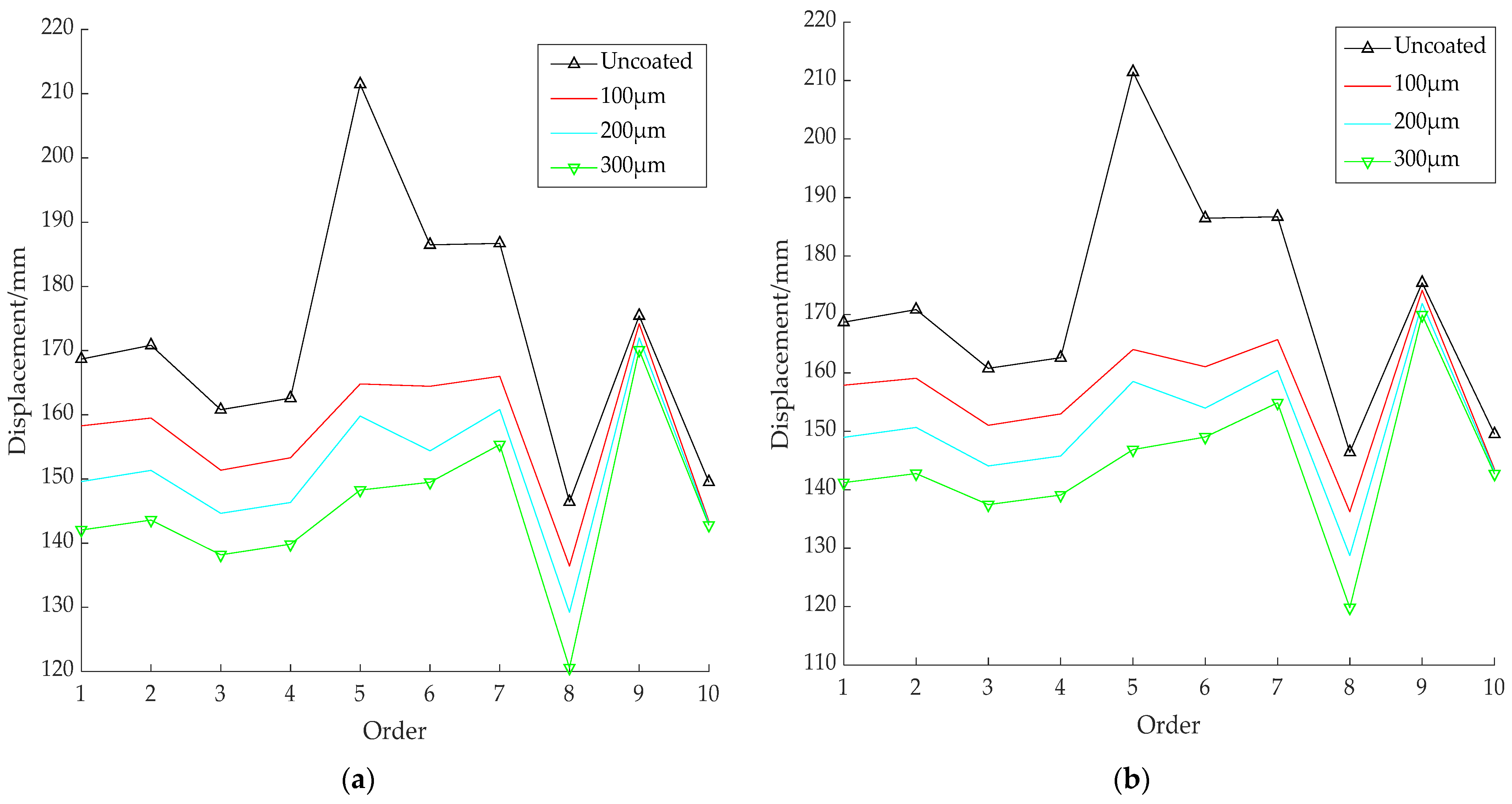
From the simulation study of a straight aviation hydraulic pipe, performed by finite element analysis, it was concluded that different coating thicknesses, coating materials, and pipeline materials have different degrees of influence on the natural frequency and the displacement of the main mode shape. As the coating thickness increased, the natural frequency offset increased, and the displacement of the main mode shape decreased. The maximum offset of the first-order natural frequency was 7.5%, and resonance could be prevented by changing the natural frequency. The maximum displacement of the main mode shape displacement was reduced to 16.28%, indicating that the hard coating could effectively suppress the vibration of the pipeline under the basic excitation of normal working conditions.
(2)
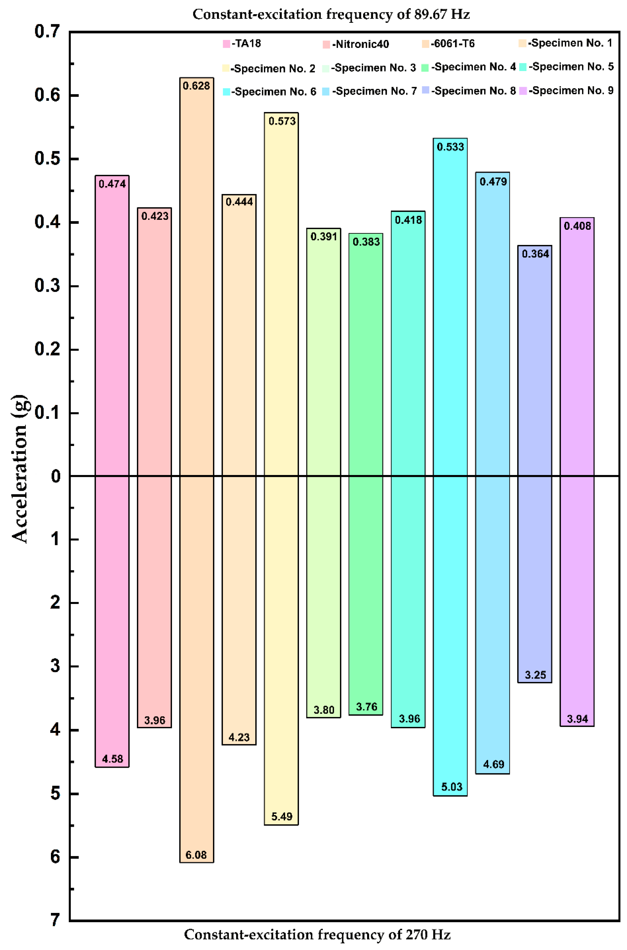
A vibration response analysis of the hard-coated aviation hydraulic pipeline under the constant-frequency simple harmonic excitation of the high- and low-pressure rotors was carried out using an orthogonal experimental design. The results showed that of the three influencing factors (hard-coating thickness, pipeline material, and hard-coating material) under high- and low-pressure constant-frequency excitation, the coating thickness had the greatest influence, and the greater the coating thickness, the lower the pipeline vibration response. The influence of the hard-coating material was the second most influential factor, and the pipeline material was the least influential.
(3)
According to the orthogonal experimental design, the best combination was a straight aviation hydraulic pipe composed of stainless steel coated with a YSZ–PTFE composite coating at a thickness of 300 μm. The vibration reduction rate of the engine under the constant-frequency excitation of the low-pressure rotor could reach 20.33%, and the vibration reduction rate under the constant-frequency excitation of the high-pressure rotor could reach 26.60%. It was proven that the YSZ–PTFE composite coating had the best vibration-damping effect among the three hard-coating materials.
(4)
The vibration response analysis of the aviation hydraulic pipeline under the constant-frequency simple harmonic excitation of the high- and low-pressure rotors was carried out by combining experiments and simulations. The average error between the experimental and simulated vibration response amplitudes was less than 5%, which proves the accuracy of the model. The accuracy and feasibility of the established model and analysis were verified, and it was confirmed that the selected hard coating can meet the demands of vibration control in practical engineering.

Author Contributions

Conceptualisation, Z.C.; data curation, J.L., C.L. and L.G.; formal analysis, Z.R. and J.L.; funding acquisition, X.Y.; investigation, Z.C.; methodology, Z.C. and J.L.; project administration, X.Y.; resources, X.Y.; software, Z.C. and Z.R.; supervision, X.Y.; validation, X.Y.; visualisation, X.Y.; writing—original draft, Z.C.; writing—review and editing, X.Y. All authors have read and agreed to the published version of the manuscript.

Funding

This study was supported by the National Natural Science Foundation of China (51775257).

Institutional Review Board Statement

Not applicable.

Informed Consent Statement

Not applicable.

Data Availability Statement

Data are contained within the article.

Acknowledgments

We sincerely thank the Beijing Power Machinery Research Institute for coating spraying and Northeastern University for providing the vibration test bench.

Conflicts of Interest

The authors declare no conflict of interest.

References

  1. Xu, E.J. The preliminary study on the integrity requirements of the aero-engine pipe structure. Aeroengine 1994, 6, 53–62. [Google Scholar]
  2. Gao, P.; Yu, T.; Zhang, Y.; Wang, J.; Zhai, J. Vibration analysis and control technologies of hydraulic pipeline system in aircraft: A review. Chin. J. Aeronaut. 2020, 34, 83–114. [Google Scholar] [CrossRef]
  3. Liu, Z.H.; Li, X.Q.; Jia, D. Crack fault analysis of hydraulic pipe for an aeroengine. Aeroengine 2020, 46, 66–70. [Google Scholar]
  4. Liu, X. Fracture failure analysis of clamp for an aeroengine. Aeroengine 2019, 45, 77–81. [Google Scholar]
  5. Liu, D. Deliberation upon advance of aeroengine development in China. J. Aerosp. Power. 2001, 3, 1–7. [Google Scholar]
  6. Lin, J.; Zhou, E.; Du, L. Literature review on vibration mechanism and fault diagnosis of the pipe system of aero-engine. Mach. Tool Hydraul. 2013, 41, 163–164. [Google Scholar]
  7. Sheng, S. Research on Influence of Pipeline Support Parameters on Vibration Characteristics of Hydraulic Piping System. Master’s Thesis, Yanshan University, Qinhuangdao, China, 2015. [Google Scholar]
  8. Bakre, S.V.; Jangid, R.S.; Reddy, G.R. Response piping system on friction support to bi-directional excitation. Nucl. Eng. Des. 2007, 237, 124–136. [Google Scholar] [CrossRef]
  9. Chiba, T.; Kobayashi, H. Response Characteristics of Piping System Supported by ViscoElastic and ElastoPlastic Dampers. J. Press. Vessel. Technol. Trans. ASME 1990, 112, 34–38. [Google Scholar] [CrossRef]
  10. Li, X. Vibration reduction analysis of aircraft hydraulic pipeline based on optimal layout of clamps. Vib. Shock. 2013, 32, 14–20. [Google Scholar]
  11. Liu, F. Study of Fluid-Solid Interaction Vibration Characteristics and Control of Hydraulic Vibratory Hammer’s Main Pipeline. Master’s Thesis, Central South University, Changsha, China, 2013. [Google Scholar]
  12. Chen, K.; Qiao, Y. Preparation of FeCrAl Cladding Materials and Effects of Cr on the Properties; Harbin Engineering University: Harbin, China, 2020. [Google Scholar]
  13. Yu, L. Damping capacity and dynamic mechanical characteristics of the plasma-sprayed coatings. Mater. Sci. Eng. A 2005, 407, 174–179. [Google Scholar] [CrossRef]
  14. Chen, Y. Vibration Analyses of the Blisk and Hard Coating Damping Design for its Vibration Reduction; Dalian University of Technology: Dalian, China, 2017. [Google Scholar]
  15. Shen, P. The Analysis and Test of Vibration Performance of the Complex Hard-Coating Blisk; Northeastern University: Shenyang, China, 2017. [Google Scholar]
  16. Du, G.Y. Damping properties of arc ion plating NiCrAlY coating with vacuum annealing. Coatings 2018, 8, 20. [Google Scholar] [CrossRef] [Green Version]
  17. Bonetti, E. Damping behavior of layered aluminium and aluminide coatings on AISI 316 austenitic steel. Coatings 2020, 10, 888. [Google Scholar] [CrossRef]
  18. Chen, Y.; Wu, H.; Zhai, J.; Chen, H.; Zhu, Q.; Han, Q. Vibration reduction of the blisk by damping hard coating and its intentional mistuning design. Aerosp. Sci. Technol. 2019, 84, 1049–1058. [Google Scholar] [CrossRef]
  19. Sun, W.; Yang, S.; Gao, J.; Yan, X. A cyclic symmetric model for the investigation of vibration reduction of hard-coating blisk. Eng. Comput. 2020, 37, 3387–3406. [Google Scholar] [CrossRef]
  20. Lv, J. Research on Dynamic Characteristics of Single-Joint Clamps for Aero-Engine External Piping. Master’s Thesis, Nanjing University of Aeronautics and Astronautics, Nanjing, China, December 2018. [Google Scholar]
  21. Cui, L. Testing and Simulation of Mechanical Properties of Metal Rubber Materials. Master’s Thesis, North University of China, Taiyuan, China, April 2016. [Google Scholar]
  22. Du, G.; Li, Z.; Tan, Z.; Li, G.; Lin, Z.; Ba, D. Damping performance of YSZ coating prepared by different EB-PVD parameters. Surf. Eng. 2019, 35, 22–28. [Google Scholar] [CrossRef]
  23. Zhong, Y.; Feng, H.; Fu, D.; Zhou, P. Application of Fiber Reinforced PTFE Composites in the Field of Vibration Reduction. In Proceedings of the 2018 3rd Asia-Pacific Electronics and Electrical Engineering Conference (EEEC 2018), Shanghai, China, 17–18 November 2018. [Google Scholar]
Figure 1. Atmospheric plasma-spraying equipment.
Coatings 12 00775 g001
Figure 2. Simplified models of (a) an aviation hydraulic pipeline and (b) the hard coating.
Coatings 12 00775 g002
Figure 3. Grid classification.
Coatings 12 00775 g003
Figure 4. Model meshing (a) without the hard coating and (b) with the hard coating.
Coatings 12 00775 g004
Figure 5. Aviation hydraulic pipeline mode shapes.
Coatings 12 00775 g005aCoatings 12 00775 g005b
Figure 6. Maximum deformation of the main vibration mode of the TA18 titanium alloy straight aviation hydraulic pipe coated with different thicknesses: (a) with the YSZ coating; (b) with the YSZ–PTFE coating.
Coatings 12 00775 g006
Figure 7. Aviation hydraulic pipeline acceleration response nephogram.
Coatings 12 00775 g007aCoatings 12 00775 g007b
Figure 8. Aviation hydraulic pipeline acceleration responses.
Coatings 12 00775 g008
Figure 9. Vibration experiment layout.
Coatings 12 00775 g009
Figure 10. INV3062V 24-bit network-distributed acquisition instrument.
Coatings 12 00775 g010
Figure 11. Vibration response under low-pressure constant-frequency excitation: (a) TA18 titanium alloy pipeline; (b) Nitronic40 stainless-steel pipeline; (c) 6061T6 aluminium alloy pipeline; (d) specimen no. 1; (e) specimen no. 2; (f) specimen no. 5; (g) specimen no. 6; (h) specimen no. 8.
Coatings 12 00775 g011aCoatings 12 00775 g011b
Figure 12. Vibration response under high-pressure constant-frequency excitation: (a) TA18 titanium alloy pipeline; (b) Nitronic40 stainless-steel pipeline; (c) 6061T6 aluminium alloy pipeline; (d) specimen no. 1; (e) specimen no. 5; (f) specimen no. 7; (g) specimen no. 8; (h) specimen no. 9.
Coatings 12 00775 g012
Table 1. Horizontal factor table.
FactorCoating Thickness
A (μm)
Coating Material
B
Pipe Material
C
Level
1100YSZ–PTFETitanium alloy
2200Al–Cu–Fe–CrStainless steel
3300YSZAluminium alloy
Table 2. Hard-coating spraying scheme table.
Experiment NumberHorizontal CombinationSpray Thickness (A)Spray Material (B)Pipe Material (C)
1A1B1C11 (100 µm)1 (YSZ-PTFE)1 Titanium alloy
2A1B2C31 (100 µm)2 (Al-Cu-Fe-Cr)3 Aluminium alloy
3A1B3C21 (100 µm)3 (YSZ)2 Stainless steel
4A2B2C22 (200 µm)2 (Al-Cu-Fe-Cr)2 Stainless steel
5A2B3C12 (200 µm)3 (YSZ)1 Titanium alloy
6A2B1C32 (200 µm)1 (YSZ-PTFE)3 Aluminium alloy
7A3B3C33 (300 µm)3 (YSZ)3 Aluminium alloy
8A3B1C23 (300 µm)1 (YSZ-PTFE)2 Stainless steel
9A3B2C13 (300 µm)2 (Al-Cu-Fe-Cr)1 Titanium alloy
Table 3. Deposition parameters.
MaterialWorking GasCurrent
(A)
Power
(Kw)
Distance
(mm)
Line Speed
(mm/min)
Average Particle Size
(μm)
YSZ–PTFE(99.9%) H2, Ar6003012080030–50
Al–Cu–Fe–Cr(99.9%) H2, Ar6003012080030–40
YSZ(99.9%) H2, Ar6003012080050–65
Table 4. Pipeline material parameters.
MaterialDensity (kg × m−3)Elastic Modulus (GPa)Poisson’s Ratio
Nitronic40 (XM-10)
S21900 stainless steel
7830180.6430.298
6061-T6 aluminium alloy281068.90.33
TA18 titanium alloy44701230.291
Table 5. Hard-coating parameters.
MaterialLength (mm)Density (kg × m−3)Elastic Modulus (GPa)Poisson’s Ratio
YSZ–PTFE4005633169.4 × 1090.32
Al–Cu–Fe–Cr4004492168 × 1090.23
YSZ4005850180 × 1090.31
Table 6. Natural frequency (Hz) of the TA18 titanium alloy straight aviation hydraulic pipe coated with the YSZ–PTFE coating at different coating thicknesses.
OrderUncoated100 (μm)200 (μm)300 (μm)
11019.9988.71976.95945.68
21049.71026.61004.3985.92
32651.22643.12634.02621.8
42753.82736.72729.92715.1
54851.74693.74543.34392.1
64928.34936.94966.14972.1
75062.75085.55087.35087.4
86681.06494.56435.66297.1
97741.27788.07870.07914.7
108072.28100.88027.18017.8
Table 7. Natural frequency (Hz) of the TA18 titanium alloy straight aviation hydraulic pipe coated with the YSZ coating at different coating thicknesses.
OrderUncoated100 (μm)200 (μm)300 (μm)
11019.9988.69976.88959.64
21049.71026.51004.2985.77
32651.22645.42637.72626.2
42753.82739.12733.52719.5
54851.74691.04537.14382.3
64928.34942.64974.94982.9
75062.75090.95096.05098.0
86681.06492.76429.96286.8
97741.27797.47886.27935.9
108072.28107.08038.18033.0
Table 8. Maximum deformation of the main vibration mode of the TA18 titanium alloy straight aviation hydraulic pipe coated with the YSZ coating at different coating thicknesses (mm).
OrderUncoated100 (μm)200 (μm)300 (μm)
1168.68158.28149.61142.06
2170.83159.48151.33143.61
3160.78151.38144.65138.18
4162.59153.30146.34139.83
5211.48164.80159.80148.28
6186.47164.43154.38149.50
7186.70165.99160.82155.35
8146.43136.44129.23120.57
9175.42174.18171.99170.08
10149.52143.41143.12142.81
Table 9. Maximum deformation of the main vibration mode of the TA18 titanium alloy straight aviation hydraulic pipe coated with the YSZ–PTFE coating at different coating thicknesses (mm).
OrderUncoated100 (μm)200 (μm)300 (μm)
1168.68157.90148.96141.22
2170.83159.09150.66142.76
3160.78151.04144.08137.45
4162.59152.96145.77139.10
5211.48163.98158.53146.86
6186.47161.06153.96149.03
7186.70165.69160.4154.90
8146.43136.24128.73119.82
9175.42174.14171.89169.90
10149.52143.46143.17142.72
Table 10. Fixed-frequency excitation vibration response results.
Acceleration Response (g)
Experiment numberExcitation frequency 89.67 HzExcitation frequency 270 Hz
10.4444.23
20.5735.49
30.3913.80
40.3833.76
50.4183.96
60.5335.03
70.4794.69
80.3643.25
90.4083.94
Table 11. Acceleration sensor parameters.
ParameterConfigurationParameterConfiguration
Sensitivity100 mv/gMounting threadM5
Frequency range0.5–9000 HzResonant frequency>25 kHz
Measuring range50 gResolution0.002 m/s2
Weight10 gDimensions13 × 22 mm2
Table 12. Orthogonal experimental results showing the vibration responses of the low-voltage rotor under constant-frequency excitation.
Experiment NumberSpray Thickness (μm) (A)Spray Material (B)Pipe Material (C)Vibration Reduction Rate
11 (100 μm)1 (YSZ–PTFE)1 Titanium alloy6.03%
21 (100 μm)2 (Al–Cu–Fe–Cr)3 Aluminium alloy4.60%
31 (100 μm)3 (YSZ)2 Stainless steel1.63%
42 (200 μm)2 (Al–Cu–Fe–Cr)2 Stainless steel11.95%
52 (200 μm)3 (YSZ)1 Titanium alloy9.56%
62 (200 μm)1 (YSZ–PTFE)3 Aluminium alloy12.95%
73 (300 μm)3 (YSZ)3 Aluminium alloy19.98%
83 (300 μm)1 (YSZ–PTFE)2 Stainless steel20.33%
93 (300 μm)2 (Al–Cu–Fe–Cr)1 Titanium alloy15.56%
K112.26%39.31%31.15%-
K234.46%32.11%33.91%-
K355.87%31.17%37.53%-
R43.61%8.14%6.38%-
Excellent solutionA3B1C3-
Table 13. Orthogonal experimental results showing the vibration responses of the high-voltage rotor under excitation at constant frequency.
Experiment NumberSpray Thickness (μm) (A)Spray Material (B)Pipe Material (C)Vibration Reduction Rate
11 (100 μm)1 (YSZ-PTFE)1 Titanium alloy6.71%
21 (100 μm)2 (Al-Cu-Fe-Cr)3 Aluminium alloy6.50%
31 (100 μm)3 (YSZ)2 Stainless steel3.83%
42 (200 μm)2 (Al-Cu-Fe-Cr)2 Stainless steel6.92%
52 (200 μm)3 (YSZ)1 Titanium alloy9.26%
62 (200 μm)1 (YSZ-PTFE)3 Aluminium alloy10.10%
73 (300 μm)3 (YSZ)3 Aluminium alloy26.25%
83 (300 μm)1 (YSZ-PTFE)2 Stainless steel26.60%
93 (300 μm)2 (Al-Cu-Fe-Cr)1 Titanium alloy10.19%
K117.04%43.41%26.16%-
K226.28%23.61%37.35%-
K363.04%39.34%42.85%-
R46.00%19.8%16.69%-
Excellent solutionA3B1C3-
Table 14. Comparison of simulation results and experimental results for hard-coated straight aviation hydraulic pipes under basic fixed-frequency harmonic excitation.
89.67 Hz270 Hz
Experiment NumberSimulation Results (g)Experimental Results (g)DeviationSimulation Results (g)Experimental Results (g)Deviation
10.4440.4521.77%4.234.034.96%
20.5730.5821.55%5.495.591.79%
30.3910.4217.13%3.803.841.04%
40.3830.3771.59%3.763.711.35%
50.4180.4353.91%3.963.921.02%
60.5330.5310.38%5.035.370.63%
70.4790.4881.84%4.694.416.35%
80.3640.3416.74%3.252.9310.9%
90.4080.4060.49%3.943.881.55%
Publisher’s Note: MDPI stays neutral with regard to jurisdictional claims in published maps and institutional affiliations.

