Article

Improvement of Heat Treatment Process on Mechanical Properties of FDM 3D-Printed Short- and Continuous-Fiber-Reinforced PEEK Composites

1
Centre for Advanced Jet Engineering Technologies (CaJET), School of Mechanical Engineering, Shandong University, Jinan 250061, China
2
Key Laboratory of High-Efficiency and Clean Mechanical Manufacture at Shandong University, Ministry of Education, Jinan 250061, China
3
National Demonstration Center for Experimental Mechanical Engineering Education, Shandong University, Jinan 250061, China
*
Author to whom correspondence should be addressed.
Coatings 2022, 12(6), 827; https://doi.org/10.3390/coatings12060827
Submission received: 13 May 2022 / Revised: 7 June 2022 / Accepted: 10 June 2022 / Published: 12 June 2022
(This article belongs to the Section Surface Characterization, Deposition and Modification)

Abstract

:
Due to the addition of short/continuous fibers with better mechanical properties, FDM 3D-printed short- and continuous-fiber-reinforced PEEK composites possess better performance than printed PEEK. However, the interlayer bonding performance becomes poor due to the layer stacking and weak fiber–resin interface adhesion. In this study, a heat treatment process was proposed to improve the interlaminar bonding properties of 3D-printed short- and continuous-fiber-reinforced PEEK composites. The effects of heat treatment temperature and time on the interlaminar shear strength, porosity and dimensional change of printed samples were studied by a single-factor experiment. Moreover, the thermal properties and fracture morphology of FDM 3D-printed fiber-reinforced PEEK composites before and after heat treatment were investigated to explore the toughening and strengthening mechanism. The experimental results showed that the mechanical properties of FDM 3D-printed fiber-reinforced PEEK composites improved by heat treatment process can be attributed to the improvement of crystallinity and interfacial bonding. The heat treatment process can also improve the infiltration and diffusion among adjacent filaments and layers, and further reduce the defects. The optimized heat treatment temperature and time were 250 °C and 6 h, respectively. The maximum ILSS of FDM 3D-printed short- and continuous-fiber-reinforced PEEK composites increased by 16 and 85% compared with untreated samples, respectively.

1. Introduction

Polyetheretherketone (PEEK) is widely used in aerospace, automotive electronics, transportation and other fields owing to its better thermophysical properties as compared to general engineering plastics [1,2]. The additive manufacturing technology of PEEK based on fused deposition modeling (FDM) emerged to satisfy the requirements of low-cost and rapid manufacturing of complex structural parts. Owing to the high melting temperature of PEEK, its crystallinity degree is greatly affected by cooling rate and thermal gradient during the layer-by-layer stacking process [3]. Moreover, if the temperature cannot be controlled appropriately, the accumulated residual stress in the formed PEEK parts easily leads to warping and delamination among layers [4,5], which significantly affects the dimensional accuracy and mechanical properties of printed PEEK [6]. Previous studies indicated that the mechanical properties of printed PEEK can reach the level of injection-molded PEEK using applicable process parameters [7,8]. However, although the finite element simulation and thermal analysis method can be utilized to guide FDM 3D printing, it is still difficult for the comprehensive mechanical properties of printed PEEK to meet the engineering requirements [9,10].
Short- and continuous-fiber-reinforced polymer composites are extensively used in additive manufacturing technology and can certainly improve the mechanical and thermal properties of polymer-based materials [11,12]. Several studies have reported on FDM 3D-printed short-fiber-reinforced PEEK composites [13,14,15,16]. These results showed that the thermal and mechanical properties of fiber-reinforced PEEK composites were significantly improved, but the internal porosity increased with the addition of short fiber. Meanwhile, the toughness and interlaminar shear strength (ILSS) of FDM 3D-printed short-fiber-reinforced PEEK composites was much lower than that of FDM 3D-printed pure PEEK [17]. However, a few studies concentrated on FDM 3D-printed continuous-fiber-reinforced PEEK composites [18,19,20]. On the one hand, PEEK owns a high melting temperature and huge melting viscosity which make it more difficult to combine with fiber, resulting in a worse interface bonding performance between fiber and PEEK [21]. On the other hand, the path planning and cutting problems of continuous-fiber printing are still to be solved [22,23]. Therefore, the process and performance of FDM 3D-printed continuous-fiber-reinforced PEEK composites remains to be further researched and studied.
The layer-by-layer stacking characteristics of FDM 3D printing inevitably lead to the poor bonding performance between layers of printed parts, which is also unavoidable for short- and continuous-fiber-reinforced composites. Scholars have proposed some methods to improve the interlaminar bonding properties of FDM 3D-printed parts. The results showed that the mechanical properties of PEEK can be strengthened by a heat treatment process [24]. Yang et al. studied the effects of different heat treatment methods on the mechanical properties of PEEK. They found that the anneal heat treatment method can obtain the best mechanical properties. However, the effect of a specific heat treatment process on the mechanical properties has not been revealed. Basgul et al. found that annealing above the glass transition temperature of PEEK cannot significantly improve the mechanical properties, but the porosity of printed PEEK decreased after annealing [25]. Luo et al. utilized the plasma laser co-assisted 3D printing process to improve the interfacial bonding behaviors of CCF/PEEK composites. After optimization, the interlaminar shear strength was increased from 5.78 to 39.05 MPa [26].
However, few research focused on the effect of the heat treatment process on the mechanical properties of short- and continuous-fiber-reinforced PEEK composites. In this paper, short- and continuous-fiber-reinforced PEEK composite samples were prepared by a self-developed FDM 3D printer for fiber-reinforced heat-resistant resin composites. The mechanical property defects of FDM 3D-printed fiber-reinforced PEEK composites were analyzed. Then, the mechanical testing samples were treated under an annealing environment. The effects of heat treatment temperature and time on interlaminar shear properties, porosity and dimensional changes of FDM 3D-printed short-fiber- and continuous-fiber-reinforced PEEK composites were studied. Finally, the mechanism of its mechanical properties’ improvement was analyzed by microstructure observation and thermal property detection.

2. Materials and Methods

Figure 1 illustrates the self-developed FDM 3D printer which can prepare short- and continuous-fiber-reinforced heat-resistant resin composites. It can be seen that the FDM 3D printer had a double-nozzle structure including printing nozzles for matrix material and continuous fiber with a fiber-cutting device. The diameter of the nozzle for the matrix material was 0.4 mm and for continuous fiber was 1 mm. The maximum nozzle temperature could reach 450 °C to meet the requirements of the PEEK melting temperature. Moreover, the FDM 3D printer was equipped with a high-temperature platform which could avoid deformation and warping due to excessive temperature difference. The printing parameters and fiber parameters of the self-developed FDM 3D printer could be customized, including nozzle temperature, layer thickness, printing speed, extrusion width, continuous-fiber co-contour turns, continuous-fiber layers, continuous-fiber filling type, continuous-fiber filling density, continuous-fiber filling angle, etc. The short-fiber-reinforced PEEK composites used in this paper were self-developed carbon-fiber- and glass-fiber-reinforced PEEK composites with a fiber content of 5 wt.% (5 wt.% CF/PEEK and 5 wt.% GF/PEEK). The heat treatment experiment of continuous-fiber-reinforced PEEK composites took 5 wt.% CF/PEEK as the matrix material and polyamide prepreg continuous carbon fiber (CCF/PA) provided by Markforged as the reinforcement material. To explore the effects of the heat treatment process on the ILSS of continuous-fiber-reinforced PEEK composites, the filling method of continuous fiber inside the ILSS sample is shown in Figure 2. According to ISO 14130:1997, for an ILSS test, the top and bottom 5 layers of the ILSS sample are 5 wt.% CF/PEEK and the middle 5 layers are the alternating area of CCF/PA and 5 wt.% CF/PEEK, which ensure structural symmetry of the ILSS sample. Moreover, the filling angle and filling density of all layers are 0° and 100%, respectively.
In this study, the two main factors affecting the annealing process of the heat treatment temperature and time were taken as the research objects. A single-factor experiment was designed to optimize the heat treatment temperature and time by taking the ILSS of FDM 3D-printed fiber-reinforced PEEK composites as the evaluation criteria. In order to determine the appropriate heat treatment temperature, the temperatures of 150, 200, 250 and 300 °C were selected according to the literature and previous experiments [27]. Firstly, under the heat treatment time of 4 h, which was selected through a series of preliminary experiments, the optimal heat treatment temperature was determined by analyzing the ILSS, microstructure and crystallinity of FDM 3D-printed fiber-reinforced PEEK composites. Then, under the optimal heat treatment temperature, the heat treatment time was optimized at 2 h, 4 h, 6 h and 8 h. The process parameters used in the FDM 3D printing and heat treatment experiment are shown in Table 1. No. 1 and No. 2 are the experimental parameters for short-fiber-reinforced PEEK composites and continuous-fiber-reinforced PEEK composites, respectively. After printing, the ILSS samples were heat-treated in an oven at different temperatures ranging from 150 to 300 °C and with different durations from 2 to 8 h, and then naturally cooled at room temperature.
The mechanical properties of fiber-reinforced PEEK composites were tested at room temperature (25 °C) on a computer-controlled universal testing machine (WDW-50E, Shidai, China) under 10 kN force transducer capacity with a loading velocity of 2 mm/min. The fracture morphology of ILSS was observed using a scanning electron microscope (SEM, JSM-7610F, JEOL Ltd., Japan) to analyze the fracture mechanism. The electrical voltage used for SEM was 5 V and the working distance was about 12 mm. The porosity of samples before and after heat treatment was measured by a digital balance based on Archimedes’ principle, which can refer to the standard of ASTM D3171. A differential scanning calorimeter (DSC, TAQ2000, TA, USA) was used to investigate the effect of the heat treatment process on the thermal properties and crystallinity of fiber-reinforced PEEK composites. About 10 mg of PEEK-based composites treated by different heat treatment processes underwent a thermal cycle, heating from 30 °C to 400 °C, then cooling down to 150 °C in a nitrogen atmosphere. The heating rate and cooling rate were both set to 10 °C/min. The percentage of crystallization ( X c ) was determined by the following Equation (1): where Δ H m is the apparent melting enthalpy, w represents the weight fraction of fiber and Δ H m ,   P E E K 0 denotes the theoretical melting enthalpy corresponding to a 100% crystalline pure PEEK. The reference value of Δ H m ,   P E E K 0 is 130 J/g, taken from the literature [16].
X c = Δ H m ( 1 w ) Δ H m ,   P E E K 0 × 100 %

3. Results and Discussion

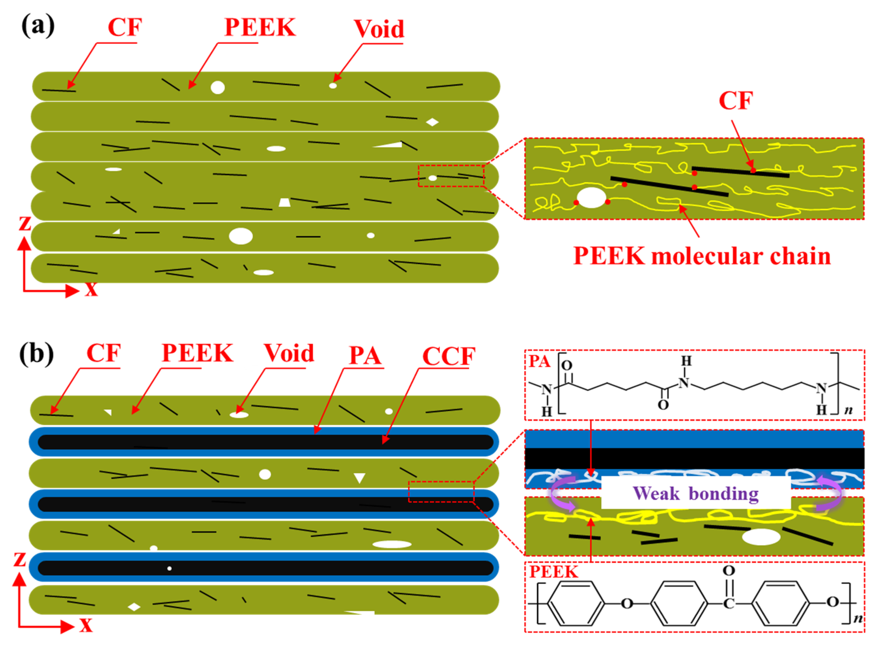
3.1. Problems Existing in FDM 3D Printing Fiber-Reinforced PEEK Composites

Figure 3a shows the schematic diagram of FDM 3D-printed short-fiber-reinforced PEEK composites. On the one hand, these short fibers played a strengthening role which sustains most of the load; thus, the composites showed higher strength and stiffness. On the other hand, the addition of short fibers increased the porosity and internal defects of the composites. Meanwhile, the disordered distribution of short fibers disrupted the regular arrangement of the PEEK molecular chain and hindered the movement of chain segments, which made the PEEK chain segments shorter and the composites brittle, as shown in Figure 3a.
The matrix material and reinforcement material for FDM 3D-printed continuous-fiber-reinforced PEEK composites were CF/PEEK and CCF/PA, respectively. Due to the stable benzene ring structure of the PEEK molecular chain with few active functional groups, it was difficult for CF/PEEK to form good interfacial bonding with CCF/PA, which resulted in poor interlaminar bonding and delamination prone to debonding and cracking, as shown in Figure 3b.

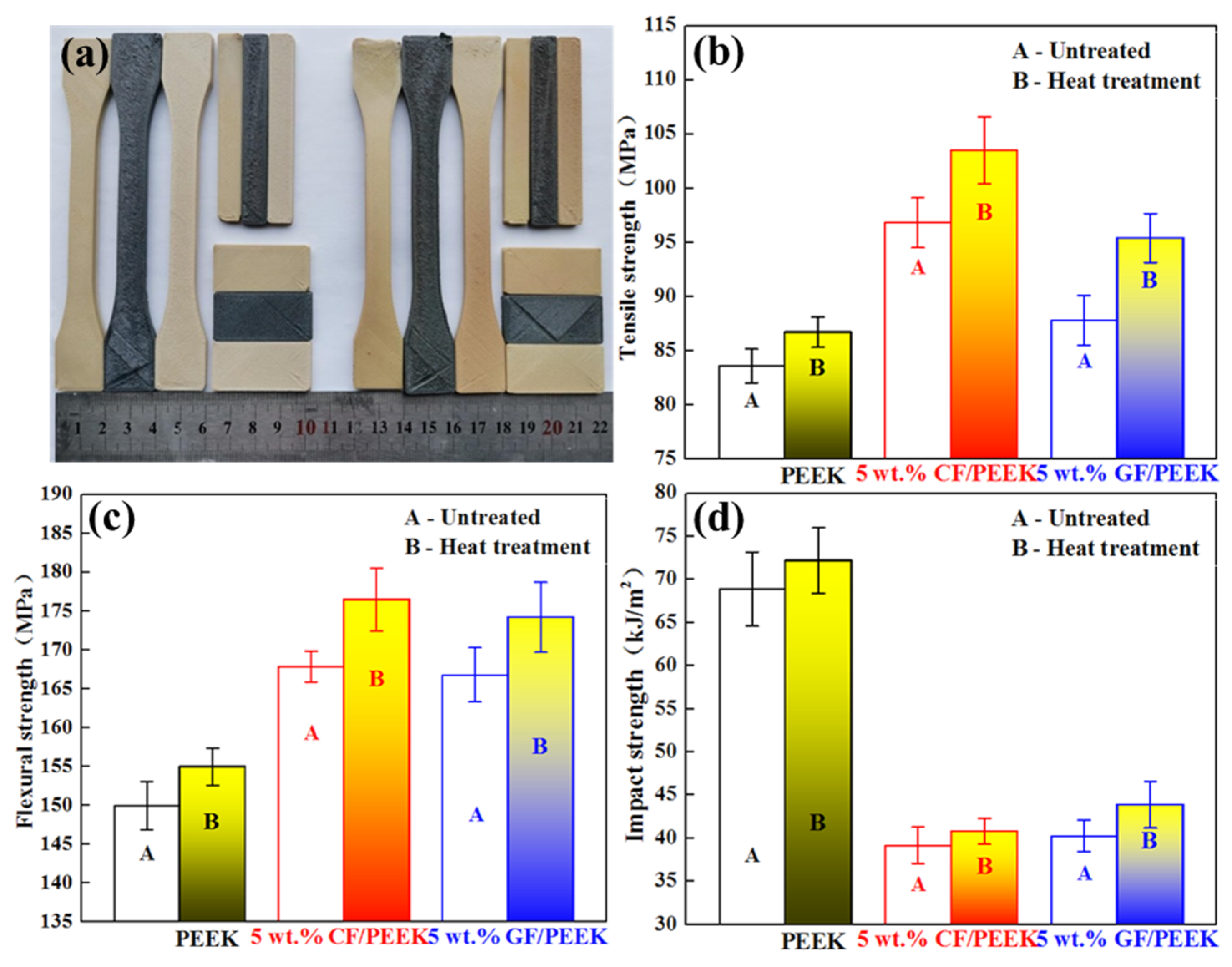
3.2. Effect of Heat Treatment on FDM 3D-Printed Short-Fiber-Reinforced PEEK Composites

Figure 4 shows the effects of different heat treatment temperatures and times on the ILSS of 5 wt.% CF/PEEK and 5 wt.% GF/PEEK. It was found that with the increase in heat treatment temperature, the ILSS of short-fiber-reinforced PEEK composites firstly increased and then decreased, as shown in Figure 4a. Specifically, when the heat treatment temperature was lower than 200 °C, the heat treatment temperature had little effect on the interlaminar bonding performance. The ILSS of printed CF/PEEK and GF/PEEK reached the maximum with a heat treatment temperature of 250 °C, which was about 10% higher than that of the untreated samples. Under the heat treatment temperature of 250 °C, the ILSS of printed CF/PEEK and GF/PEEK increased firstly and then remained unchanged with the growth of heat treatment time, as shown in Figure 4b. When the heat treatment time exceeded 6h, the ILSS of printed CF/PEEK and GF/PEEK did not increase any more.
According to DSC curves of 5 wt.% CF/PEEK under different heat treatment processes as shown in Figure 5 and thermal performance parameters in Table 2, it was found that the crystallinity of PEEK was slightly improved under the heat treatment processes of 250 °C-6 h and 300 °C-4 h as compared with untreated samples. This can be attributed to the enhanced movement ability of the PEEK molecular chain and the increased crosslinking degree of the molecular structure caused by increasing temperature. However, high temperature may lead to oxidative crosslinking between PEEK molecular chains, which weakens the mechanical properties to some extent [28]. Based on the above analysis, the optimal heat treatment process parameter for FDM 3D-printed short-fiber-reinforced PEEK is 250 °C for 6 h, which can improve its mechanical properties by 16% as compared with the untreated sample.
Figure 6 shows optical images of an interlaminar cracking pattern on the ILSS sample side surface using different heat treatment processes. It can be seen that the ILSS samples of untreated and low-temperature-treated PEEK showed the characteristics of brittle fracture with a flat fracture surface. However, under the heat treatment process of 250 °C for 6 h, the ILSS samples of CF/PEEK and GF/PEEK had the characteristics of ductile fracture, where the crack extends along the direction of loading until it stops in the middle layers of the sample. This phenomenon was particularly obvious in GF/PEEK, as shown in Figure 6b. It can be attributed to the release of residual stress in the FDM 3D-printed sample under the heat treatment process of 250 °C for 6 h [29]. Although the crystallinity of PEEK was improved, its molecular chains were still in a relaxed state with high elongation, which participates in stress release and improves the interfacial bonding strength between fiber and PEEK, delaying the initiation and propagation of cracks while resisting interlaminar shear stress.
In order to further analyze the failure mechanism, the microstructure of 5 wt.% CF/PEEK under different heat treatment processes was observed using SEM, as shown in Figure 7. It can be seen that some small pores were still distributed on the cross section of CF/PEEK after heat treatment. It is worth noting that only when the heat treatment temperature reached 300 °C did the pores inside the sample decrease significantly, which is also consistent with the results of Figure 8a. This further indicates that the temperature below 300 °C had little effect on the intermolecular infiltration diffusion, which cannot change the microstructure and porosity. As shown in Figure 8b, when using the heat treatment process of 250 °C for 6 h, the porosity and dimensional change of FDM 3D-printed 5 wt.% CF/PEEK were both less than 1%. Compared with crystallinity and molecular structure, the change of porosity is not the main cause affecting the mechanical properties. The dimensional change of the sample is positively correlated with the change of porosity. With the increase in heat treatment temperature and time, the porosity inside the sample decreased. Meanwhile, the sample size had a certain degree of shrinkage in both width and height directions. As more interlayer defects were ameliorated by heat treatment, the dimensional shrinkage in height direction was larger than that in width direction.
Figure 9 shows the mechanical properties of PEEK, 5 wt.% CF/PEEK and 5 wt.% GF/PEEK before and after the heat treatment process of 250 °C for 6 h. As can be seen from Figure 9a, the color of the samples deepened after heat treatment, which reflects the increase in crystallinity to a certain extent. Under the heat treatment process of 250 °C for 6 h, the tensile, flexural and impact properties of PEEK, 5 wt.% CF/PEEK and 5 wt.% GF/PEEK were improved by more than 5% as compared with those untreated samples. It can be seen that although the crystallinity of PEEK was improved by the heat treatment process, the impact toughness of PEEK did not decrease, which thoroughly demonstrates the contribution of heat treatment in releasing the residual stress and improving the interfacial bonding between fiber and PEEK [29].

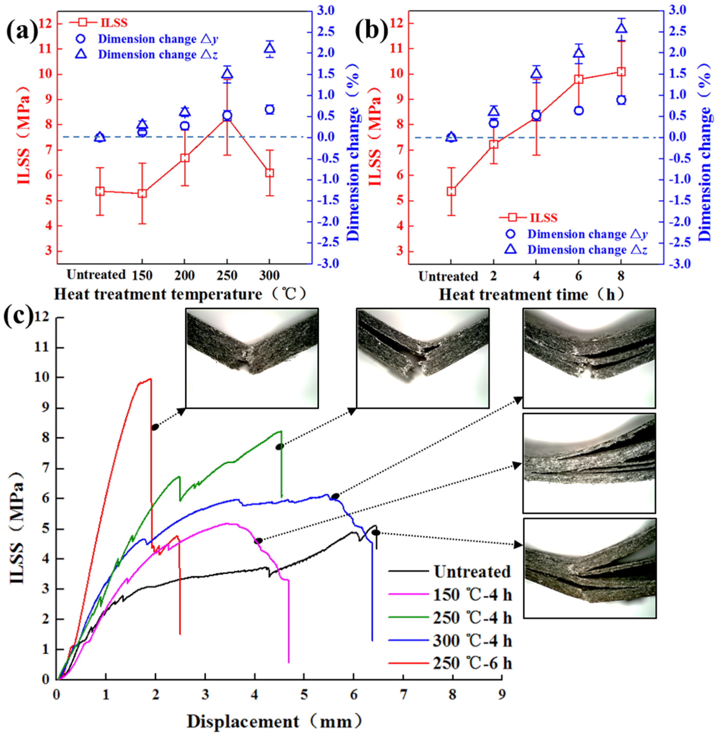
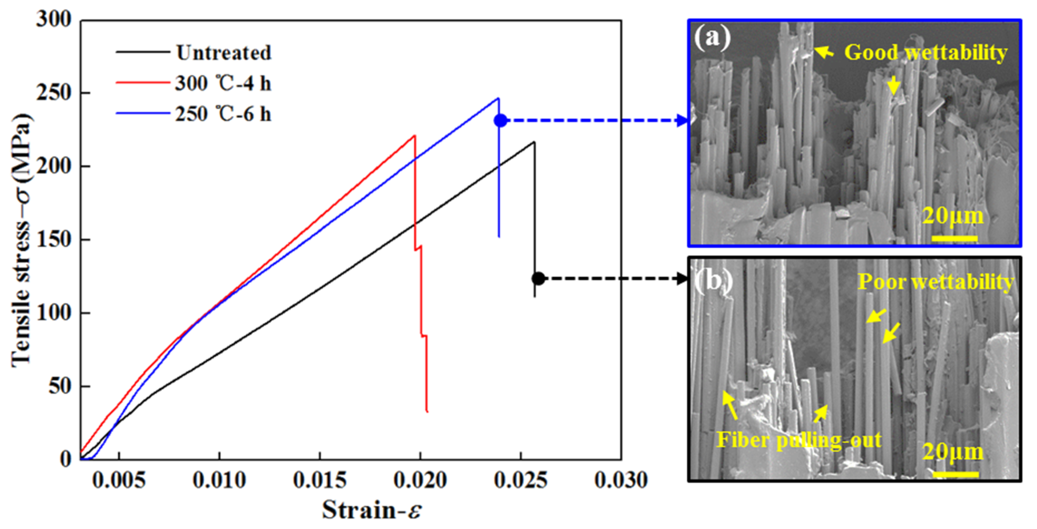
3.3. Effect of Heat Treatment on FDM 3D-Printed Continuous-Fiber-Reinforced PEEK Composites

It can be seen that the ILSS increased firstly and then decreased with the increasing heat treatment temperature, as shown in Figure 10a. The ILSS of printed continuous-fiber-reinforced PEEK composites was improved most evidently at the heat treatment temperature of 250 °C. However, the interlaminar bonding performance weakened when the heat treatment temperature rose to 300 °C. A high temperature of 300 °C can accelerate the degradation of thermal aging properties of PEEK and PA, further leading to the decline of the mechanical properties [28].
Under the optimal heat treatment temperature of 250 °C, the ILSS increased firstly and then basically remained constant with the increasing heat treatment time, as shown in Figure 10b. When the heat treatment time exceeded 6 h, the ILSS did not increase anymore, which was the same as the regularity of the heat treatment process on FDM 3D-printed short-fiber-reinforced PEEK composites. The optimal heat treatment process parameter for FDM 3D-printed continuous-fiber-reinforced PEEK is 250 °C for 6 h, which can improve its ILSS by 85% as compared with the untreated sample.
As can be seen from Figure 10c, the ILSS displacement curve presented long linear elastic deformation with small shear strain due to the heat treatment process of 250 °C for 6 h. The failure mode of the sample was characterized by brittle fracture, indicating that PA transitions from ductile to brittle after heat treatment. Meanwhile, the bonding performance of the CCF/PA layer and CF/PEEK layer was improved. However, the ILSS samples have interlaminar separations in varying degrees with a shear yield phenomenon using other heat treatment process parameters, which is caused by interlaminar shear slip under a weak interlaminar bonding performance [30].
It can be seen from Figure 10a,b that the dimension of FDM 3D-printed continuous-fiber-reinforced PEEK composite samples enlarged with the increase in heat treatment temperature and time. The change of longitudinal dimension was more obvious than that of transverse dimension, which can be attributed to the fact that the thermal expansion effect between longitudinal interlayers is more significant compared with transverse inner layers. In addition, the dimensional change of FDM 3D-printed continuous-fiber-reinforced PEEK composites after the heat treatment process was larger than that of the short-fiber-reinforced PEEK composites, which was mainly caused by the thermal expansion of PA, as shown in Figure 11. The heat treatment process can make the infiltration and diffusion of PA more perfect; however, the dimension shrinkage caused by reduction in porosity during the heat treatment process was far less than that affected by thermal expansion of PA. Nevertheless, due to the excellent thermal stability of PEEK, the effect of the heat treatment process on the expansion of short-fiber-reinforced PEEK can be negligible. Therefore, the transverse and longitudinal dimension shrinkage of short-fiber-reinforced PEEK composites printed by FDM is mainly due to the reduction in porosity.
As can be seen from Figure 12, the maximum tensile strength reached 247 MPa under the heat treatment process of 250 °C for 6 h, which was about 15% higher than that of the untreated sample. The fracture micromorphology of continuous fiber showed good interfiber infiltration with PA under the optimal heat treatment process, as shown in Figure 12a. Moreover, fewer defects were observed between continuous fiber and PA. Nevertheless, it was evidently seen that the smooth surface of continuous fiber in the untreated fracture sample was caused by the separation from PA, indicating weak bonding interface between continuous fiber and PA.
The signs of PA infiltration can be seen more intuitively from the surface topography of the printed continuous fiber, as shown in Figure 13. Under the heat treatment process of 250 °C for 6 h, PA had better melting fluidity and infiltration diffusion, which led to a smooth surface of continuous fiber without an obvious interfilament void. On the contrary, it can be seen from Figure 13a that the surface roughness and interfilament gap of the untreated continuous-fiber layer were larger than that treated under the annealing environment. However, when the heat treatment temperature reached 300 °C, the phenomenon of PA debonding was seen in the magnified image of the continuous-fiber surface, which was caused by the expansion of PA due to excessive temperature.
In conclusion, the maximum tensile strength of 5 wt.% CF/PEEK prepared by FDM 3D printing under the filling angle of ±45° can reach 103.5 MPa after the optimal heat treatment process, which is equivalent to the tensile properties of injection-molded PEEK. However, the tensile strengths of acrylonitrile butadiene styrene (ABS), polylactic acid (PLA) and polyethylene terephthalate (PETG) matrix composites with similar carbon-fiber content reported in the literature are only about half of that in this study [31,32,33], as shown in Figure 14. Compared with 10 wt.% CF/PEEK in the literature [34], 5 wt.% CF/PEEK prepared in this study had better mechanical properties owing to the use of the high-temperature platform and optimized heat treatment process parameters. As shown in Figure 14b, the maximum tensile strength of printed CCF/PEEK with fiber content of 6.6 vol.%, used in this study, can reach 247 MPa after heat treatment, which is even better than that of CCF/PA with fiber content of 11 vol.%.

4. Conclusions

In this study, a heat treatment process was proposed to improve the interlaminar bonding performance of FDM 3D-printed short- and continuous-fiber-reinforced PEEK composites. The following conclusions can be drawn:
(1)
In order to overcome the mechanical property defects of FDM 3D-printed short- and continuous-fiber-reinforced PEEK composites, the effects of heat treatment temperature and time on interlaminar shear properties, porosity and dimension changes of printed samples were studied. The toughening and strengthening mechanism was discussed by thermal properties and fracture morphology before and after the heat treatment process.
(2)
The heat treatment process mainly enhances the mechanical properties of short-fiber-reinforced PEEK composites by improving the crystallinity of PEEK and the interfacial bonding performance of fiber/PEEK. The optimal heat treatment process for FDM 3D-printed short-fiber-reinforced PEEK is 250 °C for 6 h, which can improve its mechanical properties by 16% as compared with the untreated sample. It can be attributed to the release of residual stress in the FDM 3D-printed sample. When using the heat treatment process of 250 °C for 6 h, the porosity and dimensional change of FDM 3D-printed 5 wt.% CF/PEEK are less than 1%. Compared with crystallinity and molecular structure, the change of porosity is not the main cause affecting the mechanical properties.
(3)
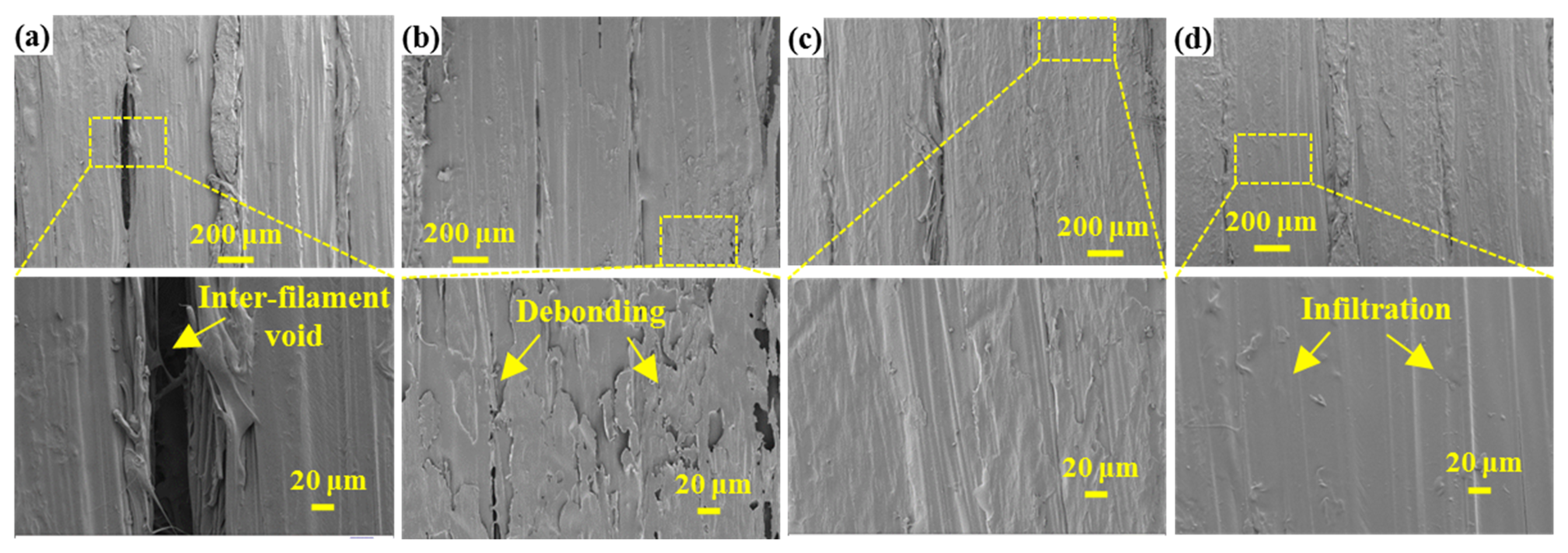
The excessive heat treatment temperature of 300 °C can lead to degradation of mechanical performance of PEEK and PA. The optimal heat treatment process is 250 °C for 6 h, which makes the infiltration and diffusion of PA more perfect, improves the wettability of PA and continuous fiber, and reduces the interfilament defects. The ILSS of continuous-fiber-reinforced PEEK composites increases by 85% as compared with the untreated sample. The dimensional change of FDM 3D-printed continuous-fiber-reinforced PEEK composites after heat treatment is larger than that of short-fiber-reinforced PEEK composites, which is mainly caused by the thermal expansion of PA. The longitudinal dimension change is more obvious than that of the transverse dimension, which can be attributed to the fact that the thermal expansion effect between longitudinal interlayers is more significant as compared with transverse inner layers.

Author Contributions

Conceptualization, P.W. and B.Z.; methodology, P.W. and B.Z.; investigation, P.W.; resources, B.Z.; data curation, P.W.; writing—original draft preparation, P.W.; writing—review and editing, P.W.; funding acquisition, B.Z. All authors have read and agreed to the published version of the manuscript.

Funding

This research was funded by the National Natural Science Foundation of China (No. 51875319) and Shandong Natural Science Foundation of China (ZR2020ZD05).

Institutional Review Board Statement

Not applicable.

Informed Consent Statement

Not applicable.

Data Availability Statement

Not applicable.

Conflicts of Interest

The authors declare no conflict of interest.

Nomenclature

FDMfused deposition modelingABSacrylonitrile butadiene styrene
3Dthree-dimensionalPLApolylactic acid
PEEKpolyetheretherketonePTEGpolyethylene terephthalate
CCFcontinuous carbon fiberDSCdifferential scanning calorimeter
CFshort carbon fiberSEMscanning electron microscope
GFshort glass fiberILSSinterlaminar shear strength
PApolyamide--

References

  1. Abate, L.; Blanco, I.; Motta, O.; Pollicino, A.; Recca, A. The isothermal degradation of some polyetherketones: A comparative kinetic study between long-term and short-term experiments. Polym. Degrad. Stab. 2002, 75, 465–471. [Google Scholar] [CrossRef]
  2. Lu, S.X.; Cebe, P.; Capel, M. Thermal stability and thermal expansion studies of PEEK and related polyimides. Polymer 1996, 37, 2999–3009. [Google Scholar] [CrossRef]
  3. Jin, L.; Ball, J.; Bremner, T.; Sue, H. Crystallization behavior and morphological characterization of poly(ether ether ketone). Polymer 2014, 55, 5255–5265. [Google Scholar] [CrossRef]
  4. Kousiatza, C.; Karalekas, D. In-situ monitoring of strain and temperature distributions during fused deposition modeling process. Mater. Des. 2016, 97, 400–406. [Google Scholar] [CrossRef]
  5. Wang, P.; Zou, B.; Xiao, H.; Ding, S.; Huang, C. Effects of printing parameters of fused deposition modeling on mechanical properties, surface quality, and microstructure of PEEK. J. Mater. Process. Technol. 2019, 271, 62–74. [Google Scholar] [CrossRef]
  6. Garcia-Gonzalez, D.; Rusinek, A.; Jankowiak, T.; Arias, A. Mechanical impact behavior of polyether–ether–ketone (PEEK). Compos. Struct. 2015, 124, 88–99. [Google Scholar] [CrossRef] [Green Version]
  7. Ding, S.; Zou, B.; Wang, P.; Ding, H. Effects of nozzle temperature and building orientation on mechanical properties and microstructure of PEEK and PEI printed by 3D-FDM. Polym. Test. 2019, 78, 105948. [Google Scholar] [CrossRef]
  8. Rinaldi, M.; Ghidini, T.; Cecchini, F.; Brandao, A.; Nanni, F. Additive layer manufacturing of poly (ether ether ketone) via FDM. Compos. Part B Eng. 2018, 145, 162–172. [Google Scholar] [CrossRef]
  9. Geng, P.; Zhao, J.; Wu, W.; Ye, W.; Wang, Y.; Wang, S.; Zhang, S. Effects of extrusion speed and printing speed on the 3D printing stability of extruded PEEK filament. J. Manuf. Process. 2019, 37, 266–273. [Google Scholar] [CrossRef]
  10. Patel, P.; Hull, T.R.; McCabe, R.W.; Flath, D.; Grasmeder, J.; Percy, M. Mechanism of thermal decomposition of poly(ether ether ketone) (PEEK) from a review of decomposition studies. Polym. Degrad. Stab. 2010, 95, 709–718. [Google Scholar] [CrossRef] [Green Version]
  11. Blanco, I. The Use of Composite Materials in 3D Printing. J. Compos. Sci. 2020, 4, 42. [Google Scholar] [CrossRef] [Green Version]
  12. Blanco, I. A Brief Review of the Applications of Selected Thermal Analysis Methods to 3D Printing. Thermo 2022, 2, 74–83. [Google Scholar] [CrossRef]
  13. Yang, D.; Cao, Y.; Zhang, Z.; Yin, Y.; Li, D. Effects of crystallinity control on mechanical properties of 3D-printed short-carbon-fiber-reinforced polyether ether ketone composites. Polym. Test. 2021, 97, 107149. [Google Scholar] [CrossRef]
  14. Li, Q.; Zhao, W.; Yang, W.; Wang, G. Flexural Properties and Fracture Behavior of CF/PEEK in Orthogonal Building Orientation by FDM: Microstructure and Mechanism. Polymers 2019, 11, 656. [Google Scholar] [CrossRef] [PubMed] [Green Version]
  15. Han, X.; Yang, D.; Yang, C.; Spintzyk, S.; Scheideler, L.; Li, P.; Li, D.; Geis-Gerstorfer, J.; Rupp, F. Carbon Fiber Reinforced PEEK Composites Based on 3D-Printing Technology for Orthopedic and Dental Applications. J. Clin. Med. 2019, 8, 240. [Google Scholar] [CrossRef] [Green Version]
  16. Wang, P.; Zou, B.; Ding, S.; Huang, C.; Shi, Z.; Ma, Y.; Yao, P. Preparation of short CF/GF reinforced PEEK composite filaments and their comprehensive properties evaluation for FDM-3D printing. Compos. Part B Eng. 2020, 198, 108175. [Google Scholar] [CrossRef]
  17. Wang, P.; Zou, B.; Ding, S.; Zhuang, Y.; Liu, J.; Li, L. Functionally graded polyetheretherketone-based composites additively manufactured by material extrusion using a transition interface design method. Compos. Part A Appl. Sci. Manuf. 2022, 158, 106977. [Google Scholar] [CrossRef]
  18. Chen, Y.; Shan, Z.; Yang, X.; Song, Y.; Zou, A. Preparation of CCF/PEEK filaments together with property evaluation for additive manufacturing. Compos. Struct. 2022, 281, 114975. [Google Scholar] [CrossRef]
  19. Luo, M.; Tian, X.; Shang, J.; Zhu, W.; Li, D.; Qin, Y. Impregnation and interlayer bonding behaviours of 3D-printed continuous carbon-fiber-reinforced poly-ether-ether-ketone composites. Compos. Part A Appl. Sci. Manuf. 2019, 121, 130–138. [Google Scholar] [CrossRef]
  20. Wang, P.; Zou, B.; Ding, S.; Li, L.; Huang, C. Effects of FDM-3D printing parameters on mechanical properties and microstructure of CF/PEEK and GF/PEEK. Chin. J. Aeronaut. 2021, 34, 236–246. [Google Scholar] [CrossRef]
  21. Stepashkin, A.; Chukov, D.; Senatov, F.; Salimon, A.; Korsunsky, A.; Kaloshkin, S. 3D-printed PEEK-carbon fiber (CF) composites: Structure and thermal properties. Compos. Sci. Technol. 2018, 164, 319–326. [Google Scholar] [CrossRef]
  22. Today, M. MarkForged develops 3D printer for carbon fibre. Reinf. Plast. 2015, 59, 12. [Google Scholar] [CrossRef]
  23. Ferreira, I.; Machado, M.; Alves, F.J.L.; Marques, A.T. A review on fibre reinforced composite printing via FFF. Rapid Prototyp. J. 2019, 25, 972–988. [Google Scholar] [CrossRef]
  24. Yang, C.; Tian, X.; Li, D.; Cao, Y.; Zhao, F.; Shi, C. Influence of thermal processing conditions in 3D printing on the crystallinity and mechanical properties of PEEK material. J. Mater. Process. Technol. 2017, 248, 1–7. [Google Scholar] [CrossRef]
  25. Basgul, C.; Yu, T.; MacDonald, D.W.; Siskey, R.; Marcolongo, M.; Kurtz, S.M. Does annealing improve the interlayer adhesion and structural integrity of FFF 3D printed PEEK lumbar spinal cages? J. Mech. Behav. Biomed. Mater. 2020, 102, 103455. [Google Scholar] [CrossRef]
  26. Luo, M.; Tian, X.; Shang, J.; Yun, J.; Zhu, W.; Li, D.; Qin, Y. Bi-scale interfacial bond behaviors of CCF/PEEK composites by plasma-laser cooperatively assisted 3D printing process. Compos. Part A Appl. Sci. Manuf. 2020, 131, 105812. [Google Scholar] [CrossRef]
  27. Rodzeń, K.; Harkin-Jones, E.; Wegrzyn, M.; Sharma, P.; Zhigunov, A. Improvement of the layer-layer adhesion in FFF 3D printed PEEK/carbon fibre composites. Compos. Part A Appl. Sci. Manuf. 2021, 149, 106532. [Google Scholar] [CrossRef]
  28. Courvoisier, E.; Bicaba, Y.; Colin, X. Multi-scale and multi-technique analysis of the thermal degradation of poly(ether ether ketone). Polym. Degrad. Stab. 2018, 151, 65–79. [Google Scholar] [CrossRef]
  29. Samy, A.A.; Golbang, A.; Harkin-Jones, E.; Archer, E.; Tormey, D.; McIlhagger, A. Finite element analysis of residual stress and warpage in a 3D printed semi-crystalline polymer: Effect of ambient temperature and nozzle speed. J. Manuf. Process. 2021, 70, 389–399. [Google Scholar] [CrossRef]
  30. Franco-Urquiza, E.A.; Escamilla, Y.R.; Llanas, P.I.A. Characterization of 3D Printing on Jute Fabrics. Polymers 2021, 13, 3202. [Google Scholar] [CrossRef]
  31. Ferreira, R.T.L.; Amatte, I.C.; Dutra, T.A.; Bürger, D. Experimental characterization and micrography of 3D printed PLA and PLA reinforced with short carbon fibers. Compos. Part B Eng. 2017, 124, 88–100. [Google Scholar] [CrossRef]
  32. Ning, F.; Cong, W.; Qiu, J.; Wei, J.; Wang, S. Additive manufacturing of carbon fiber reinforced thermoplastic composites using fused deposition modeling. Compos. Part B Eng. 2015, 80, 369–378. [Google Scholar] [CrossRef]
  33. Jiang, D.; Smith, D.E. Anisotropic mechanical properties of oriented carbon fiber filled polymer composites produced with fused filament fabrication. Addit. Manuf. 2017, 18, 84–94. [Google Scholar] [CrossRef]
  34. Pagliarulo, V.; Russo, P.; Leone, G.; D’Angelo, G.; Ferraro, P. A multimodal optical approach for investigating 3D-printed carbon PEEK composites. Opt. Lasers Eng. 2022, 151, 106888. [Google Scholar] [CrossRef]
  35. Naranjo-Lozada, J.; Ahuett-Garza, H.; Castañón, P.O.; Verbeeten, W.M.; Sáiz-González, D. Tensile properties and failure behavior of chopped and continuous carbon fiber composites produced by additive manufacturing. Addit. Manuf. 2019, 26, 227–241. [Google Scholar] [CrossRef]
  36. Matsuzaki, R.; Ueda, M.; Namiki, M.; Jeong, T.-K.; Asahara, H.; Horiguchi, K.; Nakamura, T.; Todoroki, A.; Hirano, Y. Three-dimensional printing of continuous-fiber composites by in-nozzle impregnation. Sci. Rep. 2016, 6, 23058. [Google Scholar] [CrossRef]
  37. Dickson, A.N.; Barry, J.N.; McDonnell, K.A.; Dowling, D.P. Fabrication of continuous carbon, glass and Kevlar fibre reinforced polymer composites using additive manufacturing. Addit. Manuf. 2017, 16, 146–152. [Google Scholar] [CrossRef]
  38. Pertuz, A.D.; Díaz-Cardona, S.; González-Estrada, O.A. Static and fatigue behaviour of continuous fibre reinforced thermoplastic composites manufactured by fused deposition modelling technique. Int. J. Fatigue 2020, 130, 105275. [Google Scholar] [CrossRef]
Figure 1. FDM 3D printer with double-nozzle structure for printing fiber-reinforced PEEK composites: (left) FDM 3D printer for short- and continuous-fiber-reinforced PEEK composites; (right) printing head with double-nozzle structure.
Coatings 12 00827 g001
Figure 2. FDM 3D-printed ILSS sample dimension, filling method and layer structure.
Coatings 12 00827 g002
Figure 3. Schematic diagram of FDM 3D-printed fiber-reinforced PEEK composites: (a) FDM 3D-printed short-fiber-reinforced PEEK composites; (b) FDM 3D-printed continuous-fiber-reinforced PEEK composites.
Coatings 12 00827 g003
Figure 4. Effect of heat treatment process on ILSS of short-fiber-reinforced PEEK composites: (a) heat treatment temperature; (b) heat treatment time.
Coatings 12 00827 g004
Figure 5. DSC curves of CF/PEEK under different heat treatment processes: (a) first, heating scan, (b) cooling scan. Heating rate and cooling rate are both set to 10 °C/min.
Coatings 12 00827 g005
Figure 6. Optical images of interlaminar cracking pattern on the ILSS sample side surface using different heat treatment processes: (a) 5 wt.% CF/PEEK; (b) 5 wt.% GF/PEEK.
Coatings 12 00827 g006
Figure 7. Microstructure of FDM 3D-printed 5 wt.% CF/PEEK under different heat treatment processes: (a) 150 °C-4 h; (b) 300 °C-4 h; (c) 250 °C-2 h; (d) 250 °C-6 h.
Coatings 12 00827 g007
Figure 8. Effect of heat treatment process on porosity and dimensional change of FDM 3D-printed 5 wt.% CF/PEEK: (a) heat treatment temperature; (b) heat treatment time.
Coatings 12 00827 g008
Figure 9. Mechanical properties of FDM 3D-printed PEEK, CF/PEEK and GF/PEEK before and after heat treatment process of 250 °C for 6 h: (a) samples before and after heat treatment process; (b) tensile strength; (c) flexural strength; (d) impact strength.
Coatings 12 00827 g009
Figure 10. Effect of heat treatment process on ILSS of FDM 3D-printed continuous-fiber-reinforced PEEK composites: (a) heat treatment temperature; (b) heat treatment time; (c) shear stress displacement curves.
Coatings 12 00827 g010
Figure 11. Schematic diagram to describe the effect of heat treatment process on dimensional change of FDM 3D-printed fiber-reinforced PEEK composites: (a) FDM 3D-printed short-fiber-reinforced PEEK composites; (b) FDM 3D-printed continuous-fiber-reinforced PEEK composites.
Coatings 12 00827 g011
Figure 12. Effect of heat treatment processes on tensile properties of FDM 3D-printed continuous-fiber-reinforced PEEK composites: (a) 250 °C-6 h; (b) Untreated sample.
Coatings 12 00827 g012
Figure 13. Microstructure of continuous-fiber layer surface under different heat treatment processes: (a) 150 °C-4 h; (b) 300 °C-4 h; (c) 250 °C-2 h; (d) 250 °C-6 h.
Coatings 12 00827 g013
Figure 14. Tensile strength of FDM 3D-printed fiber-reinforced PEEK composites in this study compared with those of FDM 3D-printed fiber-reinforced polymer composites in the literature [31,32,33,34,35,36,37,38]: (a) short-fiber-reinforced polymer composites; (b) continuous-fiber-reinforced polymer composites.
Coatings 12 00827 g014
Table 1. FDM 3D printing and heat treatment process parameters.
No.MaterialsNozzle Temperature
(°C)
Printing Speed
(mm/s)
Platform Temperature
(°C)
Layer Thickness
(mm)
Heat Treatment Temperature
(°C)
Heat Treatment Time
(h)
15 wt.% CF/PEEK
5 wt.% GF/PEEK
41952770.10, 150, 200, 250, 3000, 2, 4, 6, 8
25 wt.% CF/PEEK41952400.125
CCF/PA2953
Table 2. Thermal performance parameters of CF/PEEK under different heat treatment processes.
Samples T m   ( ° C ) Δ H m   ( J / g ) T c     ( ° C ) Δ H c     ( J / g ) X c   ( % )
5 wt.% CF/PEEK-untreated342.732.8303.439.526.5
5 wt.% CF/PEEK-300 °C-4 h341.832.8305.339.426.7
5 wt.% CF/PEEK-250 °C-6 h341.834.2305.238.828.0
Publisher’s Note: MDPI stays neutral with regard to jurisdictional claims in published maps and institutional affiliations.

