Article

Self-Lubricating Property of TiB2-Ni Coating in the Hot Forging Die of Aluminum Alloy

Department of Materials Science and Engineering, School of Materials Science and Engineering, Wuhan University of Technology, Wuhan 430070, China
*
Author to whom correspondence should be addressed.
Coatings 2022, 12(6), 829; https://doi.org/10.3390/coatings12060829
Submission received: 4 May 2022 / Revised: 2 June 2022 / Accepted: 8 June 2022 / Published: 13 June 2022
(This article belongs to the Topic Surface Engineered Materials)

Abstract

:
Hot die forging is a forging forming method widely used in the automobile industry, shipbuilding, and the aerospace industry. In the hot die forging process of aluminum alloy, the “mold sticking” defect often occurs and results in low productivity and short die life. Herein, we prepared TiB2 reinforced nickel-based coatings by the combined use of a plasma transferred arc and plasma melt injection method, and investigated the morphology and properties of composite coatings in hot forging die conditions. The results showed that the nickel-based coating reinforced with TiB2 generated boron-rich self-lubricating products during the sliding with aluminum alloy, and the adhered aluminum alloy on a coating surface has significantly reduced quantity and transformed morphology from rough plough to smooth layer with the increase of TiB2, which is beneficial to the surface quality of the aluminum alloy counterface. The results of this research provide valuable guidelines for the design and preparation of the coatings applied in the mold in hot die forging of aluminum alloys.

1. Introduction

Aluminum alloys are widely used in the aerospace industry, transportation, and the new energy industry for low density, high specific strength and stiffness, strong corrosion resistance and good ductility, etc. [1,2]. However, aluminum alloys tend to adhere to the harder surface of mold in high temperature plastic deformation such as hot die forging due to the mutual attraction and penetration between metal atoms, especially between aluminum atoms and iron atoms [3]. The adhesive aluminum alloy tends to weld with the mold and form a “pick-up” during a repeated high-temperature forging process, which is detrimental to the surface quality of forgings and the die life [4,5,6].
To date, lubricants are widely used in hot die forging of aluminum alloys to separate the metal-to-metal contact of molds and forgings, thereby reducing wear and improving the filling ability of aluminum alloys [7]. Common lubricants include liquid, grease, and solid lubricants. Under the high temperature and high pressure of hot die forging, solid lubricants generally perform more excellent high temperature stability, load carrying capacity, and utilization compared with liquid and grease lubricants [8], and also overcome the environmental pollution and health hazards of traditional lubricants that may result from the active substance inside such as phosphorus and sulphur.
In order to efficiently apply solid lubricants in production, self-lubricating materials prepared with solid lubricants as the second phase and metals, non-metals, or ceramics as the matrix are widely studied [9]. Generally, self-lubricating materials rely on self-lubricating film prepared by in-situ generation or surface coating technology (such as CVD, PVD) on the surface to achieve the boundary lubrication. Common solid lubricant materials include MoS2, graphite, boric acid, oxides (B2O3, TiO2), fluorides (CaF2 [10], BaF2, SrF2) and so on, which are usually limited by working conditions, cost, and physicochemical property. For example, MoS2 will oxidize with H2O to MoO3, so it is only suitable for water vapor-free environments such as vacuums [11]; soft self-lubricating materials such as graphite and CaF2 will reduce the strength and stiffness of the coating [12]. Therefore, it is necessary to develop a self-lubricating material being reliable under high temperature and high pressure for efficient and continuous production of aluminum alloy forgings.
TiB2 is a widely used ceramics material with high melting point, high stiffness, good chemical stability, and strong corrosion resistance [13]. In an aerobic and humid environment, the boron in TiB2 tends to react spontaneously with oxygen to generate boron oxide ( 2 B + 3 2 O 2 B 2 O 3 ) and further react with water to generate boric acid ( 1 2 B 2 O 3 + 3 2 H 2 O H 3 BO 3 ), both reaction products have been proven to be effective solid lubricants [14,15,16,17]. Erdemir et al. [17,18] found that a B2O3 film formed on the surface of boron-rich materials when heated, and the film reacted with H2O in the atmosphere to spontaneously generate H3BO3 when cooled, exhibiting self-lubricating properties. Yang et al. [19] prepared (TiB2 + TiC)/Ti3SiC2 coatings utilizing in situ reactions and performed dry friction experiments at room temperature with an atmospheric environment and found that oxide wear debris, including B2O3, was formed on the surface of friction pairs. Li et al. [20] investigated the tribological properties of boron-rich materials in wet environments and found that the decrease in friction coefficient was due to the formation of B2O3 tribochemical film. Kumar et al. [21] prepared a 50wt.%Ti-50wt.%TiBw composite containing TiB, TiB2, and Ti by SPS, and boric acid films were found generated on the surface of the composite during the dry sliding process at 700–900 °C, resulting in a reduction of COF. It was reported that boric acid self-lubricating film prepared on aluminum exhibited strong adhesion, low coefficient of friction (about 0.04), and low cleaning costs. In addition, a metal matrix composite (MMC) reinforced with TiB2 exhibits higher microhardness, corrosion resistance, and better wear resistance due to the strong load-bearing capacity and fixation on a soft substrate of the hard phase [19,22]. The high strength and excellent self-lubricating property of TiB2 reinforced MMC have been widely reported as above; however, there are few studies on the self-lubricating property affecting the “mold sticking” defect of aluminum alloy under the high temperature and high pressure of hot die forging.
In this paper, TiB2 reinforced Ni-based coatings were prepared by the combined use of plasma transferred arc (PTA) and plasma melt injection method (PMI). The microhardness and the thermal fatigue property of the composite coatings were tested. The friction and wear experiments of composite coatings dry sliding against 7075 aluminum alloys were carried out by pin-on-disk wear testers. The effects of TiB2-Ni coatings on the “mold sticking” defects and the wear of aluminum alloy were analyzed. This paper provides guidelines for the design and preparation of the coatings applied in the mold in hot die forging of aluminum alloys.

2. Experimental Procedures

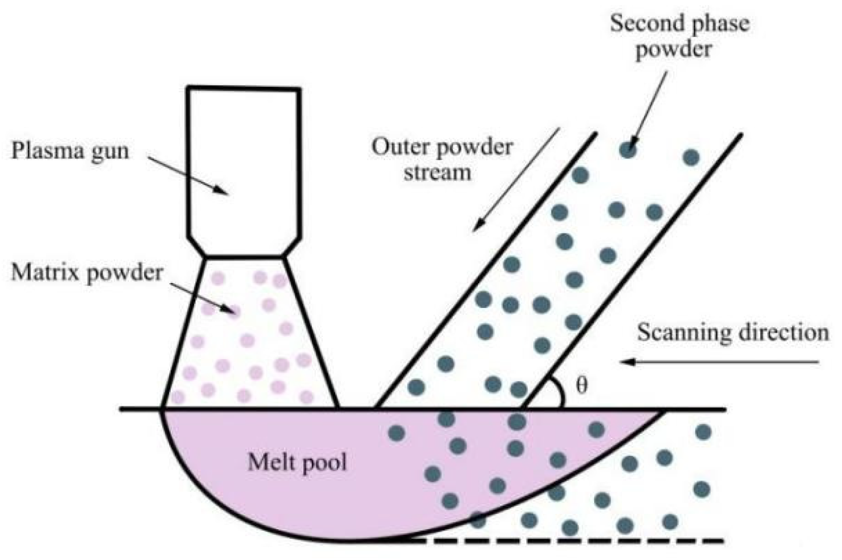
2.1. Materials and Methods

The Ni60A (C 0.5–1.1, B 3.0–4.5, Cr 15.0–20.0, Si 3.5–5.5, Fe ≤ 5.0, Ni balance) powders with a particle size ranging 75–150 μm were used as the substrate material of coatings, as shown in Figure 1a. TiB2 powders with a particle size ranging 10–30 μm were used as the reinforced ceramic composites, as shown in Figure 1b. H13 steel is a widely used hot work die steel with high wear resistance, toughness, and resistance to thermal shock, which is suitable as a hot forging die material for aluminum alloy. The H13 steel plate of 160 × 110 × 15 mm3 was used as the substrate (C 0.37, Cr 5.13, Mo 1.43, V 1.00, Si 1.00, Mn 0.34, Fe balance). The two powder materials were dried in a drying oven at 110 °C for 2 h and the H13 steel plate was ground with SiC abrasive paper (#400–#1000) and preheated in a blast furnace at 500 °C for 2 h before welding.
The coatings were prepared on an H13 steel substrate by a plasma arc welding machine (LU-F400/B400-CNC, Bangzhu Metal Material Co., Ltd., Xingtai, China). As shown in Figure 2 and Figure 3, the Ni60A powders were ejected from the powder feeding port and then melted in the plasma arc and deposited on the H13 steel plate in the protection of argon gas, while the TiB2 powders were sent into the molten pool from an outer powder injection nozzle. The heat affected zone (HAZ) of the molten pool of plasma melt injection is similar to that of conventional welding, which is not conducive to the spread of ceramic powder for its lower temperature than transferred arc zone (TAZ). The non-transferred arc zone (NTAZ), on the other hand, is located in the center of the heat source and has the highest temperature, which tends to cause burnout of the ceramic powder. Therefore, the PTA + PMI method was chosen instead of the mixed powder method to minimize the burnout of TiB2 powder, thus improving the utilization. The injection angle is chosen as 45°. Table 1 presents the technological parameters of PTA + PMI in this study. Power feed rate was calculated to control the quality percentage of TiB2 powders. The composites Ni-based coatings with different contents of TiB2 were denoted as TN5 (5 wt.%), TN10 (10 wt.%), TN15 (15 wt.%), since obvious defects in coatings showed when the content of TiB2 increased to 20 wt.%.
The H13 steel plate melted with coatings was put into the furnace to keep warm for 1 h and then cooled naturally. The specimens were cut in a direction perpendicular to the coating surface by a wire cut machine, and then ground to remove the defective layer about 0.5 mm with emery paper (#80–#1500) before polished with diamond emulsion.

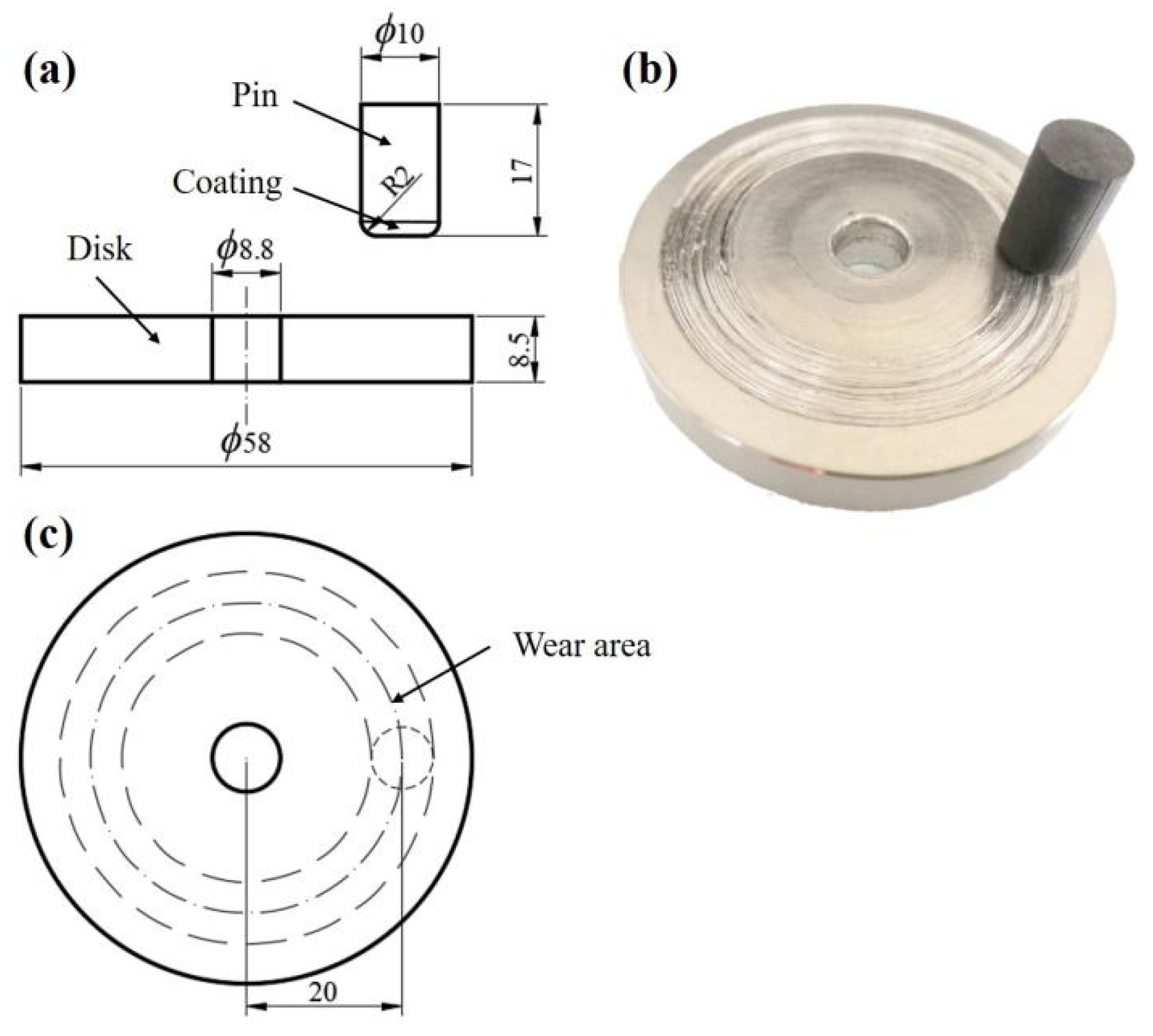
2.2. Characterization

The composition of the specimen was analyzed by an X-ray diffractometer (XRD, D8 Advance, Bruker, Germany) with Cu Kα radiation (λ = 1.54056 Å) and the scanning speed was 1°/min and the scanning angle was 30° to 100°. The microstructure and composition of the specimen were performed by scanning electron microscopy (SEM, JXA-8230/INCAX-ACT, JEOL, Tokyo, Japan) with an energy dispersive spectrometer (EDS).
Microhardness was tested on coatings surface by a microhardness tester (HMAS-C1000SZA, FULEY, Shanghai, China) with a load of 0.1 kg for a 10 s dwell time. The test at the same position was repeated 10 times at the same height, and the average value was taken after removing the maximum and minimum values.
The self-made thermal fatigue apparatus was shown in Figure 4. In one cycle, the specimen was heated to the specified temperature and kept warm for a certain time in the heating furnace, and then was moved by the lifting fixture to the water tank to cool for a period of time, followed by being moved to the heating furnace for heating again. Prior to the test, a precrack was created by a wire cutting machine. The hot forging temperature of aluminum alloy is generally 300–500 °C, the preheating temperature of H13 steel hot forging die is 250–400 °C, and the final forging temperature is 400–450 °C. Therefore, considering the local heating and flash temperature, the heating temperature of the thermal fatigue test is set to 600 and 750 °C. The specific parameters of the thermal fatigue test are shown in Table 2.
The wear tests of coatings sliding against the 7075-T6 aluminum alloy (the chemical composition is shown in Table 3) disc were conducted by a self-made pin-on-disk tribometer, as shown in Figure 5, lasting 1 h in ambient air. The temperature of 430 °C, the loads of 12 N, and the speed of 100 r/min (0.21 m/s) in the test were referred to the actual hot die forging conditions of aluminum alloy [23,24]. In addition, both aluminum alloy discs and pins were polished by emery paper (#80–#1500).

3. Results and Discussion

3.1. Composite Coating

In addition to adhesion by aluminum alloys, aluminum alloy hot forging dies are subjected to high temperature, pressure and friction as well as sudden temperature changes due to a heating–cooling process; therefore, the microhardness, thermal fatigue property, wear resistance, and adhesion to aluminum alloys of TiB2 reinforced Ni-based coatings are discussed.

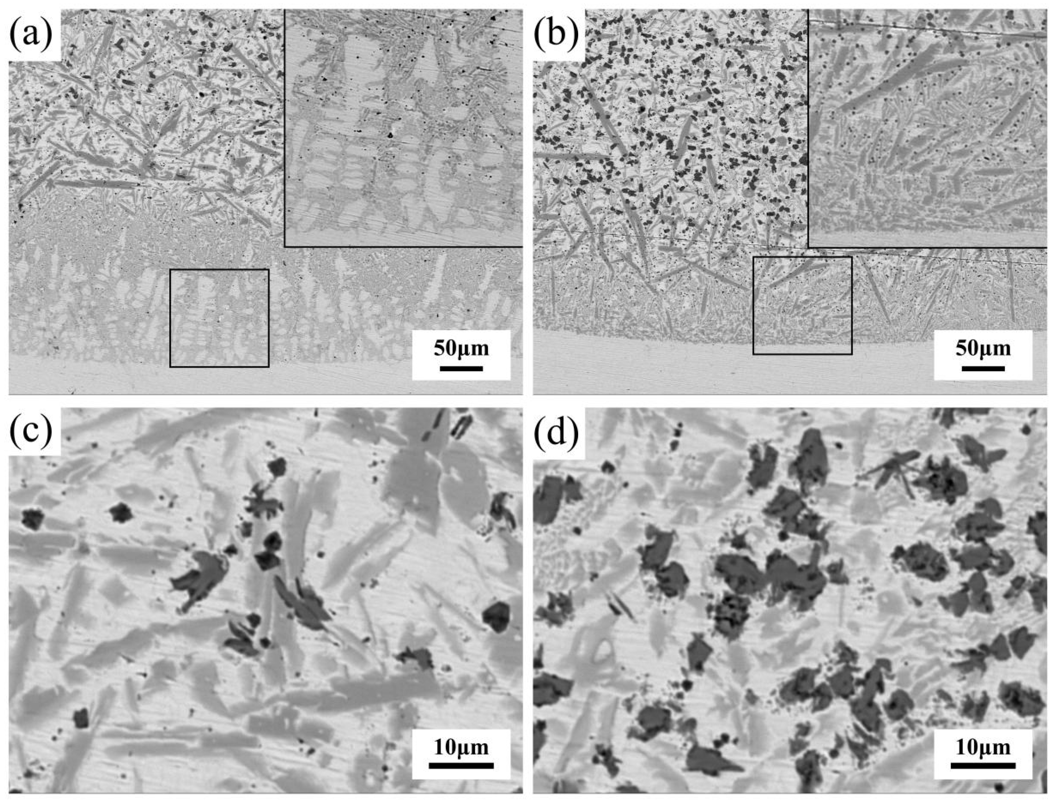
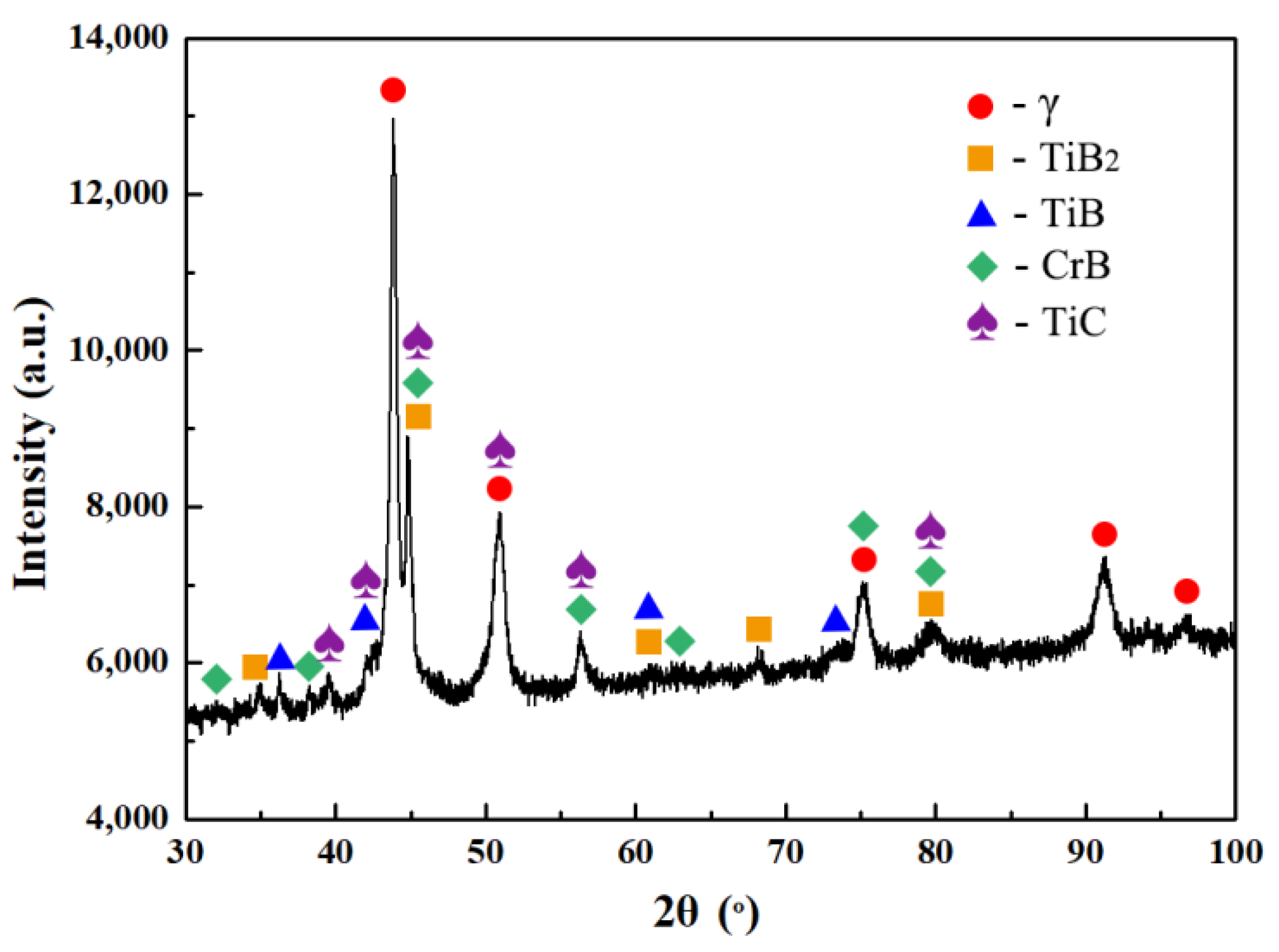
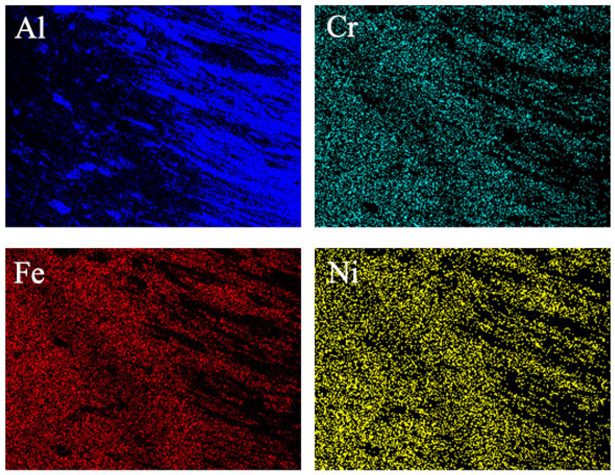
3.1.1. Microstructure and Composition

Figure 6 shows the SEM micrographs of the cross section of TN10 and TN15 coatings. The coatings with a thickness of about 3 mm have no obvious cracks, and the clear and continuous interfaces which indicate metallurgical bonds between coatings and matrix are realized. There are few pores in the coatings, which may be due to gas trapping caused by the large fluid viscosity induced by the material particles [25,26], or because the high melting point of TiB2 makes it difficult to melt, while the high thermal conductivity of the substrate drives the solidification of the melt pool. The addition of TiB2 inhibited the growth of dendrites at the interfacial transition zone, as shown in Figure 6a,b, indicating that the temperature gradient of the melt pool was disturbed. The grey strip-shaped phase, flower-like eutectic structure, acicular phase, and black blocky phase were observed to be uniformly distributed in the upper-middle part of the composite coatings, as shown in Figure 6c,d. The chemical composition of the phases with different morphologies was determined using EDS point analysis. Combined with the XRD spectrum of TN15 (Figure 7) and previous studies [27], the black blocky phases are mainly TiB2, TiB, TiC, and CrB; the white matrix is the γ-(Fe, Ni) solid solution phase; and the gray strip-shaped phase is rich in Fe, Cr, and Ni.
To explore the impact of TiB2 content on the hard phase, the quantity and area fraction of black blocky phase in randomly selected SEM images (magnification 400) of the top cross section of TN5, TN10, and TN15 were calculated by MATLAB. The quantity of black blocky phase in TN5, TN10, and TN15 were 1268, 892, and 806, with an area fraction of 6.17%, 18.67%, and 30.94%, respectively, illustrating a tendency of the hard phases in the coating to aggregate with the increase of TiB2.

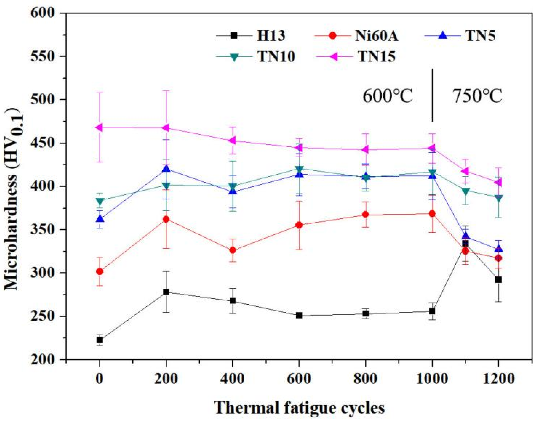
3.1.2. Microhardness

The microhardness distribution over the cross section of the coating along the depth direction is shown in Figure 8. The curves can be roughly divided into three zones as cladding zone (0–1.8 mm), transition zone (1.8–2.5 mm), and the substrate (2.5–3.2 mm). The small fluctuation of curves in the cladding zone implies that the coating has a relatively uniform organization. The obviously steep increase of the microhardness near the interface was attributed to the diffusion of alloying elements in molten pool and the selective hardening caused by Cr and Ni during the cooling process. The average microhardness of Ni60A, TN5, TN10, and TN15 specimens (0–1.8 mm from the surface) was calculated as 314.89 ± 19.74 HV0.1, 364.06 ± 12.56 HV0.1, 400.83 ± 12.89 HV0.1, 463.02 ± 20.09 HV0.1, respectively. The microhardness of the coatings increased with TiB2 increased, which was due to the distribution of hard phases TiB2, TiC, and CrB in the coatings.

3.2. Thermal Fatigue Property

No cracks were produced in all specimens during 0–1000 cycles at a temperature of 600 °C. In 1000–1200 cycles at a temperature of 750 °C, the Ni-based coatings, TN5, TN10, and TN15 produced cracks in 1000–1050 cycles, while the H13 steel produced cracks in 1150–1200 cycles. There is a main crack extending from the bottom of the precrack perpendicular to the coating towards the H13 steel substrate in every specimen as shown in Figure 9. The crack in TN5 is transcrystalline while the crack in TN10 is intercrystalline probably because the increase in TiB2 enhances the bonding strength of the grain [28].
The crack lengths in different coatings are listed in Table 4, in which it is clear that the TiB2 reinforced phase exacerbates the expansion of thermal fatigue crack in the Ni-based coating. During the continuous heating–cooling cycles, stress and strain are generated by the temperature gradient between the surface and inside of the coating, and the differences in thermal expansion coefficient and elastic modulus of Ni-based alloys and reinforced particles further exacerbate the local accumulation of heat stress and thus the crack [28,29]. Instead of detecting Ti and B near the crack in TN15, an Fe-rich oxide layer was formed because of oxygen, cooling water, and high temperature, which promoted crack extension for low thermal expansion and fragility [30].
The variation of microhardness of the specimen surface with the increase of thermal fatigue cycles is shown in Figure 10. In thermal fatigue cycles at 600 °C, surface hardening occurs in H13 steel, Ni-based coating, and TN5 in the early stages (0–400 cycles), with little change in hardness in the mid-late periods (400–1000 cycles). The hardening of the specimen surface is mainly due to stress concentration and hard oxide layer caused by heating–cooling alternation, while softening is mainly due to the reduction of dislocation density and the aggregation and coarsening of carbides. The hardness curves for TN10 and TN15 consistently show small fluctuations from 0–1000 cycles, indicating that the degree of hardening and softening of the coating surface becomes smaller or similar with the increase of TiB2 [29].
Temperature factor has a dramatic effect on the surface hardness [31]. When the temperature is increased to 750 °C, the local plastic strain further increases and exceeds the yield strength of the material and initiates crack, and the accumulated thermal stress released as the crack extends, leading to softening of the coating [28].
The TiB2 reinforced Ni-based coating did not produce thermal fatigue crack in 1000 cycles at 600 °C, and the hardness of the composite coating fluctuated less as TiB2 was increased. Since the usual hot forging temperature of aluminum alloys is 300–500 °C, although TiB2 exacerbates the thermal fatigue crack, the thermal fatigue performance of TN15 is considered adequate for aluminum alloy hot die forging.

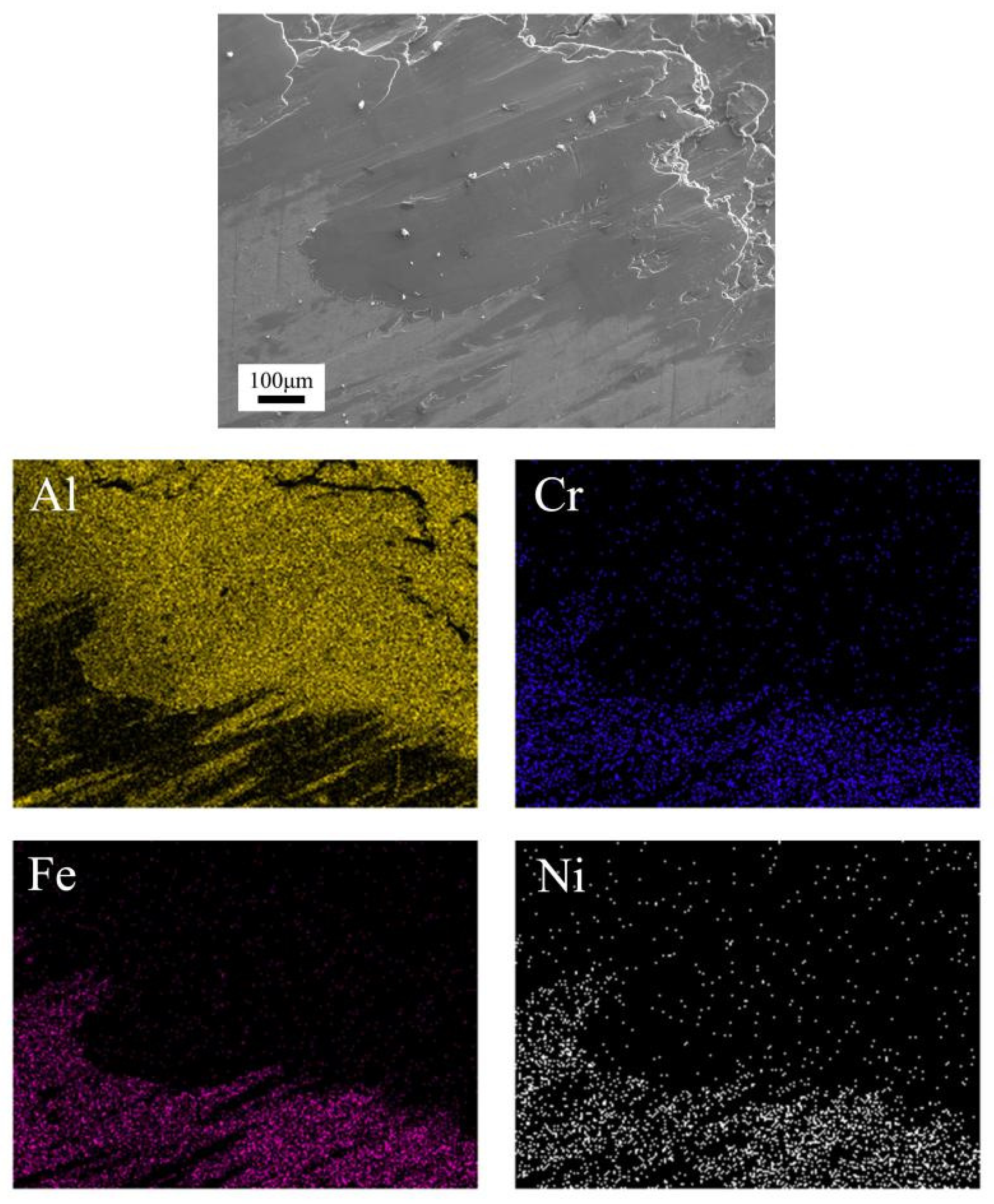
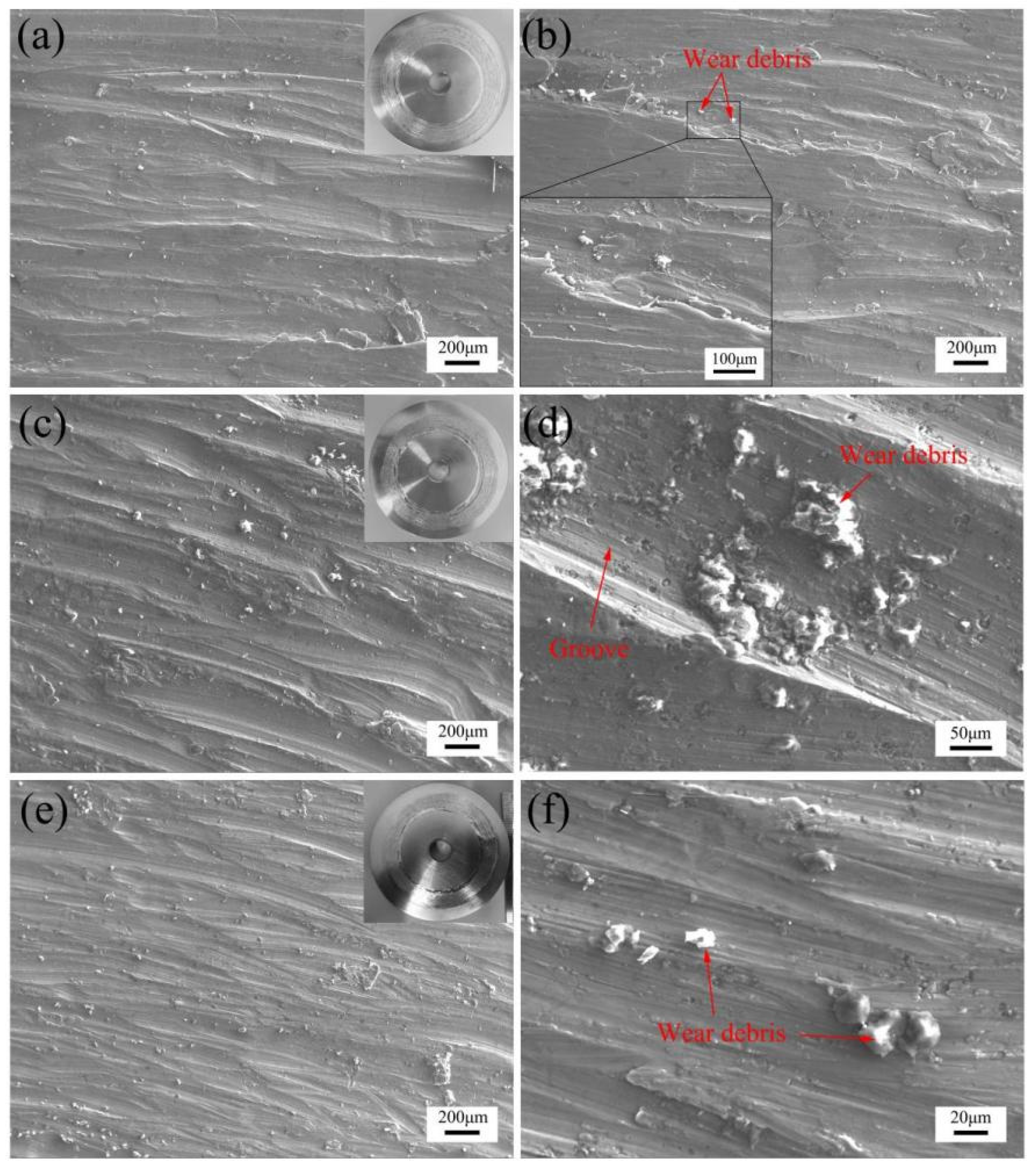
3.3. Wear Behavior and Adhesion

The variation of friction coefficients of the pins in the first hour of the wear test are shown in Figure 11. Due to the severe adhesion of aluminum alloy, the fluctuation of friction coefficient of H13 steel was the largest. Ni-based coating has a smaller friction coefficient than H13 steel because it reduced the aluminum alloy adhered to H13 steel by isolating the contact, but its friction coefficient curve still maintained a large fluctuation until 50 min. The running-in period of TN5 is longer than TN15, while the friction coefficient of TN10 always maintains a certain fluctuation during the friction process. The average friction coefficients of TN5, TN10, and TN15 are 0.51, 0.50, and 0.38, respectively. In general, TiB2 helps to shorten the running-in period of the composite coating and reduce its friction coefficient.
Weight changes of the pins and Al-7075 disks in dry friction wear test are shown in Figure 12. The increased weight of pins is considered the adhesion of aluminum alloy instead of the oxidation of coating in this research. The weight changes of the H13 steel and its aluminum disc are the highest due to the severe adhesion by the aluminum alloy, while the weight changes of Ni-based coating and its aluminum disc significantly reduce because it isolates the H13 steel from the aluminum disc. The weight gain of TN5, TN10, and TN15 are 73.68%, 75.66%, and 93.42% less than those of Ni-based alloys, respectively, corresponding to 35.29%, 36.15%, and 64.76% less weight loss of aluminum alloy discs, which means TiB2 can effectively reduce the weight loss of aluminum alloy disc and the adhesion of aluminum alloy on the composite coating.
The wear morphology of pins as shown in Figure 13 is conducive to reveal the wear mechanism and the aluminum alloy adhesive condition. It can be seen that a large number of grooves filled by a bright white substance (and the bright white substance was proved to be mainly from an aluminum alloy disc by EDS planar scanning, as shown in Figure 14) are distributed on TN5; the grooves on TN10 are reduced and the major adhesive form of aluminum alloy transfers to lamellar structure; aluminum alloy on TN15 further reduced to small fish-scaled flakes and less grooves. Apparently, the “mold sticking” defect on the surface of composite coating undergoes significant improvement with the increase of TiB2.
According to Bowden–Tabor law of nano-scale friction, since aluminum alloys are softer than TiB2 reinforced Ni-based coating, it is more likely to transfer to the coating from a disk after severe plastic deformation and fracture under friction with uneven parts of counterparts, called transferred aluminum alloys. The transferred aluminum alloy is also mixed with debris generated by the composite coating, as well as oxides and carbides. The transferred aluminum alloy will deform and migrate when sliding against the disc because of similar hardness, forming aluminum alloy furrows as shown in Figure 13a. Therefore, from the perspective of hardness, the high hardness helps to reduce the rough grooves caused by wear on the coating, thus reducing the accumulation of transferred aluminum alloy on the grooves and the plastic deformation of the disc.
At the early stage of dry sliding, there were less oxide and boric acid generated on the surface of coatings. The transferred aluminum alloy was extruded under high temperature and pressure and adhered to the coating in the form of lamellar structure. These smooth layers had led to a decrease of friction coefficient, and also caused irregular fluctuations due to being destroyed and rebuilt during the friction process. On the subsequent sliding process, the lubricant film (mainly boric acid) gradually formed on the surface of coatings, reducing the reconstructed transferred aluminum alloy layers. It was reported that the boron inside the coating tends to diffuse to surfaces with higher oxygen potential and oxidize to replenish the depleted lubricant layer [32]. Therefore, in the mid to late process of dry sliding, the formation and consuming of the lubricant film on the surface of coatings gradually converged to a dynamic equilibrium and the fluctuation of friction coefficient decreased.
Multi-layer transferred aluminum alloy was observed on TN10, as shown in Figure 15, and, because the lubricant film was gradually formed on the surface of coating in the continuous wear process, the aluminum alloy was likely to adhere on the already formed transferred aluminum alloy layers. The multi-layer structure was considered as one of the reasons for the practically maintained weight changes of TN10 from TN5 in the pin-on-disk test, as shown in Figure 12.
In addition, pits more than 100 μm in diameter and filled mostly with aluminum alloy and oxides were observed on the surface of TN10 after wear test, as shown in Figure 13d. No loose debris was found around the pits, indicating that mild adhesive wear may have occurred on TN10. These pits may be formed at the early stage of sliding when the lubricant film had not yet formed, or formed after the exposure of fresh material due to the local failure of lubricant film. In contrast, almost no pits were observed on TN15, which can be attributed to the thick lubricant film formed from sufficient boron in TN15. These pits can serve as micro-traps for capturing wear debris to reduce wear and accommodate solid lubricant particles to improve lubrication condition, and simultaneously cause serious abrasive wear to the counterface [32,33].
The morphology of aluminum alloy discs was investigated by SEM to determine the effect of TiB2 on the surface quality of aluminum alloy forgings, as shown in Figure 16. All discs were covered in grooves on the surface, presenting typical characteristics of abrasive wear. Apparently, the grooves on the disc of TN15 were finer than the discs of TN5 and TN10, indicating the beneficial effect of the increase of TiB2 in the composite coating on the aluminum alloy counterface. However, the similar size of the grooves on the discs of TN5 and TN10 meant that the increased content of TiB2 from 5 to 10 wt.% in the composite coatings did little to improve the surface quality of the corresponding aluminum alloy counterface, even though the morphology of the adhered aluminum alloy on coatings became significantly smoother. In addition, “island” structures were observed on the aluminum alloy disc of TN5, which were mechanically mixed layer (MML) formed by the accumulation of fine debris lapped and sintered during the friction process, while almost no MML was observed on the surface of the aluminum discs of TN10 and TN15.
One obvious phenomenon is that the debris on discs increases with the increase of TiB2 in coatings. The chemical composition of randomly selected debris was shown in Table 5. The debris on discs of TN5 and TN10 (Figure 16b,d) mainly contained aluminum alloys, coating composition, oxides, carbides, and little boron. A large amount of boron and no titanium was detected in the debris on the disc of TN15 (Figure 16f), which confirmed that the boron had a tendency to replenish the boron-rich lubricant consumed on the coating surface, while titanium tended to retain inside the coating. The boron-rich products formed on the surface of coatings increased with the TiB2, which reacted with water and oxygen in the air to generate boric acid, an efficient solid lubricant, to avoid the metal-to-metal contact of friction pairs, thereby not only reducing friction coefficient but also reducing the transferred aluminum alloy on the coating surface and the abrasive wear of counterpart [21,34]. In the friction process, the debris mixed with the boric acid stripped from the lubricant film can serve as lubricant particles and move between the friction surfaces.
It should be pointed out that the increase of debris on the aluminum disc does not mean more wear because, during the friction process, a portion of debris is transformed into adhesion on the coating or extruded to the edge and fall off. Previous studies have shown that boric acid has a good affinity for aluminum [35], that is to say, the high content of boric acid contributes to debris sticking on the aluminum alloy. This boron-rich debris is an advantage for the surface quality of friction pairs; however, the retained debris with high hardness or large size is detrimental to the surface quality of the soft aluminum alloy simultaneously, as shown in Figure 16a,c, where the micro-ploughing on the disc of TN10 did not improve compared with the disc of TN5. In general, if the generated solid lubricants (including the lubricant film on the surface of coating and the lubricant debris between the friction surfaces) is not enough to separate the friction surfaces to eliminate the negative effects of hard debris, the wear will deteriorate, especially on the softer surface, with the increased TiB2 in the composite coatings.
In addition, as mentioned above, multi-layer transferred aluminum alloys were observed on TN10 but not TN15. In addition to the small surface area of the transferred flakes on TN15, which was difficult to be adhered to, the sufficient boron-rich lubricant debris between the friction surfaces was believed to inhibit the accumulation of the aluminum alloy layers and play an important role in eliminating the multi-layer transferred aluminum alloy.

4. Conclusions

In this paper, Ni-based coatings reinforced with different contents of TiB2 were prepared by the combined use of plasma transferred arc and plasma melt injection method. The results are as follows:
(1)
TiB2 was beneficial to the hardness of the Ni-based composite coating. The hardness of the nickel-based composite coatings increased by 15.61%, 27.29%, and 47.04% compared with the normal nickel-based coating when the content of TiB2 was 5, 10, and 15 wt.%, respectively.
(2)
Both the normal nickel-based coating and the nickel-based coatings reinforced with 5, 10, and 15 wt.% TiB2 had no crack in the first 1000 thermal fatigue cycles at 600 °C. In the subsequent 200 cycles at 750 °C, thermal fatigue cracks appeared in all coatings and were more severe in the TiB2 reinforced nickel-based composite coatings.
(3)
The TiB2 reinforced phase promotes the generation of boron-rich products on the surface of nickel-based composite coatings during the dry sliding against the aluminum alloy under loads of 12 N at 430 °C. The boron-rich products formed self-lubricating film and debris on TiB2-Ni coatings, which was beneficial to reduce friction coefficient, mitigate the “mold sticking” defect of aluminum alloy, and transform the morphology of transferred aluminum alloy from rough plough to smooth layer.
(4)
With the increase of TiB2, a larger bulk hard phase tends to accumulate in the prepared nickel-based composite coatings, which led to the formation of hard debris on the surface. The increased hard debris may intensify the abrasive wear of the counterface if the self-lubricating film was incomplete or weak.
(5)
In view of the significantly reduced transferred aluminum alloy on coatings as well as the higher hardness than normal nickel-based coatings and the thermal fatigue performance under 600 °C, the TiB2 reinforced Ni-based coatings were considered as a potential self-lubricating coating in hot die forging of an aluminum alloy.

Author Contributions

Z.W., T.F., B.X., H.W., P.Y. and X.P. contributed equally to this work. All authors have read and agreed to the published version of the manuscript.

Funding

This work was supported by the National Natural Science Foundations of China (Grant No. 51475346).

Institutional Review Board Statement

Not applicable.

Informed Consent Statement

Not applicable.

Data Availability Statement

Not applicable.

Acknowledgments

The authors acknowledge the National Natural Science Foundations of China (Grant No. 51475346) for its grant and support.

Conflicts of Interest

The authors declare no conflict of interest.

References

  1. Stoycheva, S.; Marchese, D.; Paul, C.; Padoan, S.; Juhmani, A.S.; Linkov, I. Multi-criteria decision analysis framework for sustainable manufacturing in automotive industry. Clean Prod. 2018, 187, 257–272. [Google Scholar] [CrossRef]
  2. Hirsch, J. Recent development in aluminium for automotive applications. Trans. Nonferrous Met. Soc. China 2014, 24, 1995–2002. [Google Scholar] [CrossRef]
  3. Riahi, A.R.; Alpas, A.T. Adhesion of AA5182 aluminum sheet to DLC and TiN coatings at 25 °C and 420 °C. Surf. Coat. Technol. 2007, 202, 1055–1061. [Google Scholar] [CrossRef]
  4. Challen, J.M.; Oxley, P.L.B. An explanation of the different regimes of friction and wear using asperity deformation models. Wear 1979, 53, 229–243. [Google Scholar] [CrossRef]
  5. Sigworth, G.K.; Donahue, R.J. The Metallurgy of Aluminum Alloys for Structural High-Pressure Die Castings. Int. J. Metalcast. 2020, 15, 1–16. [Google Scholar] [CrossRef]
  6. Rokni, M.R.; Zarei-Hanzaki, A.; Roostaei, A.A.; Abedi, H.R. An investigation into the hot deformation characteristics of 7075 aluminum alloy. Mater. Des. 2011, 32, 2339–2344. [Google Scholar] [CrossRef]
  7. Gali, O.A.; Shafiei, M.; Hunter, J.A.; Riahi, A.R. The tribological behavior of PVD coated work roll surfaces during rolling of aluminum. Surf. Coat. Technol. 2014, 260, 230–238. [Google Scholar] [CrossRef]
  8. Hampson, M.R.; Roberts, E.W.; Cropper, M.D.; Watters, R.B.; Forster, D.J. Towards the effective solid lubrication of ball bearings operating at high temperature. Proc. Inst. Mech. Eng. Part J.-J. Eng. Tribol. 2008, 222, 1041–1049. [Google Scholar] [CrossRef]
  9. Jiang, C.; Wang, H.J.; Li, M.L.; Yan, S.S.; Yao, Z.H.; Liu, Q.Y. Preparation and Properties of High-Temperature Self-Lubricating Materials Based on H13 Steel. J. Mater. Eng. Perform. 2020, 29, 7830–7842. [Google Scholar] [CrossRef]
  10. Adam, P.; Mateusz, K.; Natalia, M.; Michał, K. Wear behavior of self-lubricating boride layers produced on Inconel 600-alloy by laser alloying. Wear 2019, 426–427, 919–933. [Google Scholar]
  11. Baran, O.; Bidev, F.; Cicek, H.; Kara, L.; Efeoglu, I.; Kucukomeroglu, T. Investigation of the friction and wear properties of Ti/TiB2/MOS2 graded-composite coatings deposited by CFUBMS under air and vacuum conditions. Surf. Coat. Technol. 2014, 260, 310–315. [Google Scholar] [CrossRef]
  12. Su, Y.F.; Zhang, Y.S.; Song, J.J.; Hu, L.T. Tribological Behavior and lubrication mechanism of self-lubricating ceramic/metal composites: The effect of matrix type on the friction and wear properties. Wear 2017, 372, 130–138. [Google Scholar] [CrossRef]
  13. Munro, R.G. Material properties of titanium diboride. J. Res. Natl. Inst. Stand. Technol. 2000, 105, 709–720. [Google Scholar] [CrossRef] [PubMed]
  14. Erdemir, A. Tribological properties of boric acid and boric acid forming surfaces: Part 1, Crystal chemistry and self-lubricating mechanism of boric acid. In Society of Tribologists Lubrication Engineers Annual Conference; Argonne National Labs: Denver, CO, USA, 1990. [Google Scholar]
  15. Morón, R.C.V.; Rodriguez, G.; Jiménez-Tinoco, L.F.; Amador, A.M.; Méndez-Méndez, J.V.; Escobar-Hernández, J.; Calderon, C.D.R.; Nava-Sánchez, J.L. Multipass Scratch Behavior of Borided and Nitrided H13 Steel. J. Mater. Eng. Perform. 2018, 27, 3886–3899. [Google Scholar] [CrossRef]
  16. Karakas, M.S.; Gunen, A.; Kanca, E.; Yilmaz, E. Boride Layer Growth Kinetics of Aisi H13 Steel Borided with Nano-Sized Powders. Arch. Metall. Mater. 2018, 63, 159–165. [Google Scholar]
  17. Erdemir, A.; Bindal, C.; Zuiker, C.; Savrun, E. Tribology of naturally occuring boric acid films on boron carbide. Surf. Coat. Technol. 1996, 86–87, 507–510. [Google Scholar] [CrossRef]
  18. Erdemir, A.; Halter, M.; Fenske, G.R. Preparation of ultralow-friction surface films on vanadium diboride. Wear 1997, 205, 236–239. [Google Scholar] [CrossRef] [Green Version]
  19. Yang, J.; Gu, W.; Pan, L.M.; Song, K.; Chen, X.; Qiu, T. Friction and wear properties of in situ (TiB2 + TiC)/Ti3SiC2 composites. Wear 2011, 271, 2940–2946. [Google Scholar] [CrossRef]
  20. Li, J.; Zhang, X.J.; Wang, H.P.; Li, M.P. Microstructure and mechanical properties of Ni-based composite coatings reinforced by in situ synthesized TiB2 + TiC by laser cladding. Int. J. Min. Met. Mater. 2013, 20, 57–63. [Google Scholar] [CrossRef]
  21. Rahul, K.; Maksim, A.; Le, L.; Irina, H. Sliding wear performance of in-situ spark plasma sintered Ti-TiBw composite at temperature up to 900 °C. Wear 2021, 476, 203663. [Google Scholar]
  22. Li, X.Q.; Gao, Y.M.; Yang, Q.X.; Pan, W.; Li, Y.F.; Zhong, Z.C.; Song, L.C. Evaluation of tribological behavior of B4C–hBN ceramic composites under water-lubricated condition. Ceram. Int. 2015, 41, 7387–7393. [Google Scholar] [CrossRef]
  23. Yang, Y.B.; Xie, Z.P.; Zhang, Z.M.; Li, X.B.; Wang, Q.; Zhang, Y.H. Processing maps for hot deformation of the extruded 7075 aluminum alloy bar: Anisotropy of hot workability. Mater. Sci. Eng. A 2014, 615, 183–190. [Google Scholar] [CrossRef]
  24. Guo, L.G.; Yang, S.; Yang, H.; Zhang, J. Processing map of as-cast 7075 aluminum alloy for hot working. Chin. J. Aeronaut. 2015, 28, 1774–1783. [Google Scholar] [CrossRef] [Green Version]
  25. Amado, J.M.; Tobar, M.J.; Alvarez, J.C.; Lamas, J.; Yañez, A. Laser cladding of tungsten carbides (Spherotene (R)) hardfacing alloys for the mining and mineral industry. Appl. Surf. Sci. 2009, 255, 5553–5556. [Google Scholar] [CrossRef]
  26. Zhou, C.Y.; Zhao, S.S.; Wang, Y.B.; Liu, F.L.; Gao, W.Y.; Lin, X.C. Mitigation of pores generation at overlapping zone during laser cladding. J. Mater. Process. Technol. 2015, 216, 369–374. [Google Scholar] [CrossRef]
  27. Cao, L.L.; Xia, Y.Z.; Cui, H.Z.; Li, Q.P.; Zhu, B.W.; Wang, Q.B. Microstructural characteristics of TiB2-TiC-NiAl composite coatings via Plasma Cladding Process. Surf. Eng. 2019, 35, 997–1002. [Google Scholar] [CrossRef]
  28. Pan, C.G.; Liu, D.D.; Zhao, C.X.; Chang, Q.M.; He, P. Corrosion and Thermal Fatigue Behaviors of TiC/Ni Composite Coating by Self-Propagating High-Temperature Synthesis in Molten Aluminum Alloy. Coatings 2017, 7, 203. [Google Scholar] [CrossRef] [Green Version]
  29. Klobčar, D.; Tušek, J.; Taljat, B. Thermal Fatigue of Materials for Die Casting Tooling. Mater. Sci. Eng. A 2008, 472, 198–207. [Google Scholar] [CrossRef]
  30. Klobčar, D.; Kosec, L.; Kosec, B.; Tušek, J. Thermo fatigue cracking of die casting dies. Eng. Fail. Anal. 2012, 20, 43–53. [Google Scholar] [CrossRef]
  31. Persson, A.; Hogmark, S.; Bergstrom, J. Simulation and evaluation of thermal fatigue cracking of hot work tool steels. Int. J. Fatigue 2004, 26, 1095–1107. [Google Scholar] [CrossRef]
  32. Erdemir, A. A crystal-chemical approach to lubrication by solid oxides. Tribol. Lett. 2000, 8, 97–102. [Google Scholar] [CrossRef]
  33. Nuraliza, N.; Syahrullail, S.; Razak, D.M.; Azwadi, C.S.N. Influence of micro-pits on sliding motion under low speeds for block-on-disk tribotester. Particul. Sci. Technol. 2016, 34, 754–763. [Google Scholar] [CrossRef]
  34. Hu, Z.B.; Li, H.J.; Fu, Q.G.; Xue, H.; Sun, G.L. Fabrication and tribological properties of B2O3 as friction reducing coatings for carbon-carbon composites. New Carbon Mater. 2007, 22, 131–134. [Google Scholar] [CrossRef]
  35. Wei, J.J.; Erdemir, A.; Fenske, G.R. Dry Lubricant Films for Aluminum Forming. Tribol. Trans. 2000, 43, 535–541. [Google Scholar] [CrossRef]
Figure 1. Morphology of the powder materials: (a) Ni60A; (b) TiB2.
Coatings 12 00829 g001
Figure 2. Schematic illustration of the PTA + PMI method.
Coatings 12 00829 g002
Figure 3. Non-transferred arc zone (NTAZ), transferred arc zone (TAZ), and heat affected zone (HAZ) in the molten pool.
Coatings 12 00829 g003
Figure 4. Schematic diagram of thermal fatigue testing apparatus.
Coatings 12 00829 g004
Figure 5. Sample diagram of pin-on-disc wear test: (a) dimensions of pin and disc (mm); (b) contact diagram of pin and disc; (c) schematic diagram of the wear area.
Coatings 12 00829 g005
Figure 6. SEM images of the coatings from the cross section: (a) the interface between TN10 and H13 substrate; (b) the interface between TN15 and H13 substrate; (c) the magnified image of the uniform microstructure in the upper-middle part of TN10; (d) the upper-middle part of TN15 with uniform microstructure.
Coatings 12 00829 g006
Figure 7. The XRD patterns of the representative TN15 coating.
Coatings 12 00829 g007
Figure 8. Microhardness profile along the depth direction of the coatings.
Coatings 12 00829 g008
Figure 9. The microscopic morphology of different samples after 1200 cycles: (a) Ni60A; (b) TN5; (c) TN10; (d) TN15.
Coatings 12 00829 g009
Figure 10. Surface microhardness of different samples during thermal fatigue cycles.
Coatings 12 00829 g010
Figure 11. Friction coefficient of different specimens.
Coatings 12 00829 g011
Figure 12. Column showing the weight changes for the disc and pin.
Coatings 12 00829 g012
Figure 13. SEM micrographs of the worn surface of pin: (a) TN5; (b) TN10; (c) TN15; (d) the etch pits filled with aluminum alloy on TN10.
Coatings 12 00829 g013
Figure 14. EDS planar scanning results of Figure 13a.
Coatings 12 00829 g014
Figure 15. Multi-layer transferred aluminum alloy on the TN10.
Coatings 12 00829 g015
Figure 16. SEM micrographs of the surface of aluminum alloy discs worn against: (a,b) TN5; (c,d) TN10; (e,f) TN15.
Coatings 12 00829 g016
Table 1. Technological parameters of PTA + PMI.
ParametersWelding Current (A)Carrier Gas (L/min)Welding Speed (mm/min)Vibration Extent (mm)Vibration Frequency (times/min)Spray Distance (mm)
TiB2-Ni60A12032075010
Table 2. Parameters of the thermal fatigue test.
PeriodHeating Temperature (℃)Holding Time of Heating (s)Cooling Temperature (℃)Holding Time of Cooling (s)Cycles
160012020101000
27506002010200
Table 3. Chemical composition of Al-7075 (wt.%).
SiFeCuMnMgCrZnTiOtherAl
0.40.51.2–2.00.32.1–2.90.18–0.285.1–6.10.20.15Bal.
Table 4. Propagation depth of the main crack after 1200 cycles.
SampleNi60ATN5TN10TN15
Crack depth (μm)223.2920.0897.51302.6
Table 5. EDS results of the debris on different aluminum alloy discs.
DebrisBCOAlTiFeMgSiCuMnNiCr
Disc (TN5)019.1024.2011.41016.191.8427.270000
009.551.58088.390000.4800
Disc (TN10)001.8293.7500.431.5901.800.330.290
001.8493.5600.611.7401.570.220.270.19
Disc (TN15)60.1721.601.8914.0900.420.340.401.08000
46.179.251.0339.9400.350.4502.350.4600
Publisher’s Note: MDPI stays neutral with regard to jurisdictional claims in published maps and institutional affiliations.

