Article

The Characterization of Running-In Coatings on the Surface of Tin Bronze by Electro-Spark Deposition

1
Technical Services Department, Sumy National Agrarian University, 40021 Sumy, Ukraine
2
School of Mechanical and Electrical Engineering, Henan Institute of Science and Technology, Xinxiang 453000, China
3
School of Material Science and Engineering, Henan University of Science and Technology, Luoyang 471003, China
*
Authors to whom correspondence should be addressed.
Coatings 2022, 12(7), 930; https://doi.org/10.3390/coatings12070930
Submission received: 19 May 2022 / Revised: 24 June 2022 / Accepted: 25 June 2022 / Published: 30 June 2022

Abstract

:
Antifriction materials, such as silver, copper, Babbitt B83, and graphene oxide (GO), were used to prepare running-in coatings on the surface of bronze QSn10-1 by electro-spark deposition (ESD). The analyses of mass transfer, roughness, thickness, morphology, composition, nanoindentation, and tribological properties of the coatings were investigated. The results showed that the running-in coatings were dense with refined grains that were uniformly distributed and in a metallurgical bond state with the tin bronze substrate. At optimum process parameters, the mass transfer was 244.2 mg, the surface roughness was 15.9 μm, and the thickness of the layers was 160 μm. The diffraction peaks clearly indicated the phases corresponding to α-Sn, SbSn, Cu6Sn5, and Cu, and a phase of Ag3Sn appeared. The modulus and the hardness of the running-in coatings were 24.9% and 14.2% of the substrate, and the deformation ratio of the coatings was 10.2% higher than that of the substrate. The friction coefficient of the running-in coatings was about 0.210 after the running-in stage, which was 64.8% of that of the substrate (0.324). The main wear mechanism of the running-in coatings under optimal process parameters is plastic deformation, scratching, and slight polishing. The running-in coating deformation under the action of high specific loads provides the automatic adjustment of parts and compensation for manufacturing errors.

1. Introduction

Because the working states of parts vary greatly, their surface is the most important place to carry the load [1]. Therefore, the safe and stable operation of mechanical equipment directly depends on the surface quality of machine parts [2]. The wear and failure of mechanical equipment parts usually start from the surface; therefore, in order to improve the stability and durability of mechanical parts, it is very important to strengthen the surface quality of the parts [3,4]. Functional coating is one of the most effective methods to improve the surface quality of machine parts [5,6,7]. A functional coating for a friction unit (FU) is used on curvilinear and flat surfaces through various mechanisms, such as turbo-compressor units, electric motors, power engineering units, power transmission systems, etc. The reliability and stability of sliding bearing friction elements depend mainly on the quality of the manufacturing process, the quality of the functional coating, and the installation and maintenance work [8]. There are always deviations from ideal geometry in the manufacturing process of plain bearings, and additional errors are produced in the installation process of the bearing bush. These errors are the direct reasons for the reduction in the actual contact area and the stress concentration of functional coating during running-in. The facilitation of running-in conditions and improvement of the friction surface operating regime in the post-running-in period may be provided by improving the FU and more closely fitting to “beds” by applying a layer of soft metals to contact surfaces by electro-spark deposition (ESD). The plastic deformation of soft functional coatings (Ag, Cu, B83, or composite materials) under different loads makes it possible for parts to automatically adjust and compensate for manufacturing errors.
In the operation of the sliding bearing bush, the tin bronze bearing bush has good heat transfer, but the friction coefficient is slightly higher, while the Babbitt alloy bearing bush has a small friction coefficient, but the fatigue resistance performance is sharply reduced when the temperature rises, which seriously affects the reliability and durability of the bearing bush. Bearing copper-based alloys exhibit better mechanical properties compared with the Babbitt [9,10,11]. Therefore, there is an urgent need to build a functional coating for bronze bearings to improve the surface running state. There are many methods to create functional coatings, but research on depositing a soft running-in coating on the surface of a tin bronze bearing bush by electro-spark alloying technology to improve the friction environment is less abundant.
Tin bronze has excellent thermal conductivity and can remarkably conduct the energy generated by friction during the operation of the sliding bearings [12,13]. Soft metal silver is often used in heavy-load and high-speed sliding bearing bushes, which have excellent plastic deformation performance, fatigue resistance, and corrosion resistance. The wettability between metallic silver and copper is very good, which is beneficial for improving the metallurgical bonding performance between the electro-spark deposition coatings. However, the friction coefficient and hardness of metallic silver are slightly higher, and the performance of metallic silver as a running-in coating alone is not sufficient. In the composite coatings, the ε-phase (Cu6Sn5) is formed by the combination of copper and tin in the tin-based Babbitt alloy, which is beneficial to grain refinement and the metallurgical bonding of the coatings [10,14,15].
Therefore, silver and copper are considered to be suitable as transition coatings in electro-spark deposition engineering. The tin-based Babbitt alloy B83 has good embedding and compliance and can play the roles of anti-friction and anti-scuffing in the process of bearing operation; especially in the initial running-in process of operation, it is a particularly excellent surface running material [16,17,18]. Graphene has been used to improve tribological properties due to its extraordinary properties [19,20,21]. Graphene oxide (GO) is considered a promising material for reducing friction and wear owing to its structural features [22,23,24]. Therefore, adding the GO to the coatings is beneficial to improve the friction and wear properties of the surface.
Running-in coatings were prepared on the surface of bronze QSn10-1 by electro-spark deposition using silver, copper, Babbitt B83, and graphene oxide (GO) alternately. The morphology, composition, nanoindentation, and tribological properties of the functional coatings were analyzed.

2. Materials and Methods

The experimental research methods consisted of adapting existing technology to produce running-in coatings using the ESD method to the working conditions, design, and technological features of the bearing bush.

2.1. The Experimental Materials

The tin bronze material QSn10-1 (Cu 89.10%, Sn 9.38%, P 0.72%, others 0.80%) was cut to a size of 25 mm × 29 mm × 4 mm as the substrate. Silver (99.99%), copper (99.99%), and Babbitt B83 (Sn 83.10%, Sb 11.02%, Cu 5.83%, others 0.05%) materials were used to make the electro-spark deposition electrodes with a diameter of 3 mm. Graphene oxide was a dispersible solution of 4 mg/mL with water as the solvent. The materials for the experiments were provided by Zhejiang Shenfa Bearing Co., LTD. (Zhuji, China).
The surfaces of the substrates and the electrodes were abraded with abrasive papers of different granularities, in turn, to ensure that the surface roughness was not more than 1 μm. Before the electro-spark deposition, the substrates and the electrodes were cleaned for 20 min in absolute ethyl alcohol by an ultrasonic cleaning machine to remove impurities and oil stains from the surface.

2.2. Deposition Process Parameters

A DZ-4000III electro-spark surfacing machine produced by the Institute of Surface Engineering Technology of the China Academy of Agricultural Mechanization Science and Technology (Beijing, China) was used. The DZ-4000III electro-spark deposition equipment is equipped with a control panel that can change the electrical parameters, such as the discharge voltage, energy storage capacitor, discharge frequency, etc. The welding gun of this equipment can control the rotation speed and direction of the electrode.
The moving speed of the electrodes during electro-spark deposition was about 2 mm/s. The discharge frequency process parameter of the first layer was 3 kHz, the discharge frequency of the second layer was 4 kHz, and the frequency of the third and fifth layers was 5 kHz. Electro-spark deposition was carried out at room temperature using a hand-held welding torch under an argon (99%) atmosphere with a flow rate of 10 L/min to protect the deposition area from external influences.
The GO solution was applied to the surface of the specimens by the manual pre-coating method, and then the specimens were dried by natural air, followed by the fifth layer with the B83 electrode. After the first electro-spark deposition of B83, there were many small pores on the surface, and the graphene oxide solution entered the B83 through the pores. After drying, the second electro-spark deposition of B83 was carried out. The graphene oxide thus entered B83 as an antifriction additive.
The detailed process parameters for the electro-spark deposition running-in coatings are shown in Table 1.

2.3. Properties Investigation

The sample mass was weighed using a Mettler Toledo AL204 (Shanghai, China) balance accurate to 0.1 mg.
A Bruker Contour GT-k1 (Mannheim, Germany) three-dimensional optical profiler was used to measure the surface roughness and surface topography of electro-spark deposition.
ESD-treated surface morphology and wear scars were analyzed using scanning electron microscopy (SEM) with an FEI Quanta 200 (Brno, Czech Republic). The elemental composition of the coating’s surface was characterized by energy dispersive spectroscopy (EDS) in scanning electron microscopy.
The phase composition of the coatings under investigation was analyzed by the X-ray diffraction method using a Bruker D8 Advance A25 (Karlsruhe, Germany) X-ray diffractometer with Cu-Kα radiation.
A small section was metallographically cut from the cross-section of the electro-spark-deposited running-in coating specimen and then embedded in a phenolic resin for cross-sectional topography and elemental distribution analysis. After polishing and cleaning, in order to reveal elements of the granular structure, the surfaces of the samples were subjected to etching with 4 %wt nitric acid ethanol and an exposure time of 10 s. The ESD-treated cross-section morphology of the running-in coatings was analyzed using SEM and metallographic microscopy with a LECIA DMi8 M (Wetzlar, Germany).
The nanoindentation properties of the running-in coatings were determined by a KLA-Tencor Nano Indenter G200 (Milpitas, CA, USA). The nanoindentation measurements were conducted at a load of 500 mN with a dwell time of 1 s.
An assessment of tribological properties was performed in a ball-on-plate reciprocating rig on an MWF-500 tribometer (Jinan, China). The study investigated the tribological properties of ESD layers under dry friction conditions. The test temperature was 25 °C. The low sliding velocity of 20 mm/s was chosen to ensure boundary lubricating conditions and was maintained constant for all the stripes. The track length was 6 mm. The 8 mm diameter bearing steel (GCr15) ball was used as a counter-face. The applied loads were 5 N, 10 N, and 15 N. For the initial 600 s, the applied load was 5 N; for the following 600 s, the applied load was 10 N, and the applied load was 15 N for the final 600 s.

3. Results and Discussion

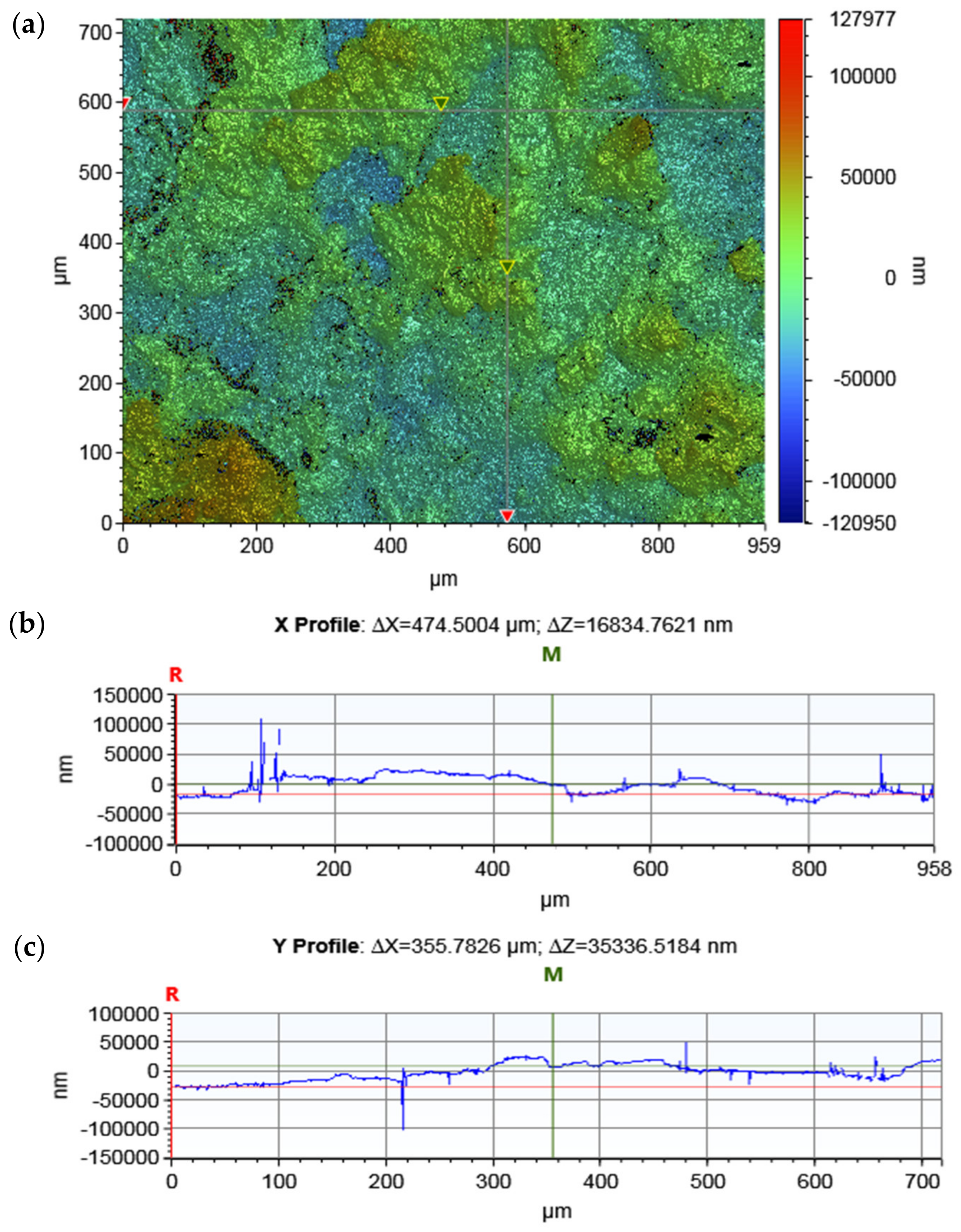
3.1. The Mass Transfer, Roughness, and Thickness Characteristics of the Running-In Coatings

In this study, the analysis of deposition on mass transfer, roughness, and thickness of the running-in coatings was investigated, as shown in Table 2.
Electro-spark deposition running-in coatings are the result of gradual accumulation through multiple discharges and a large number of deposition points [5,25,26]. The mass transfer is usually considered one of the most important indexes to evaluate the performance of electro-spark deposition [27,28,29]. At the initial stage of electro-spark deposition, the mass of running-in coatings increases the most obviously. With an increase in deposition time, the mass of the substrate increases slowly. Finally, the mass of the matrix remains essentially unchanged. This is because with an increase in the electro-spark deposition time, the oxide or nitride on the surface of the coating increases, the residual stress on the surface of the coating increases, and the bonding force of the surface coatings decreases, which causes the splashing of molten materials to occur more easily during the deposition process and hinders the further increase in the weight of the coatings.
This test used a precision electronic balance with a precision of 0.1 mg to measure the mass of tin bronze samples before and after electro-spark deposition, as shown in Table 2.
As can be observed in Table 2, increasing the pulse energy in the ESD process promoted the transfer of the mass. The minimum value of mass transfer was 90.8 mg for specimen 1, and the maximum value of mass transfer was 550.1 mg for specimen 3.
A three-dimensional optical profiler was used to measure the surface roughness and surface profile of electro-spark deposition running-in coatings. The surface roughness of the running-in coatings is shown in Table 2. As can be seen in Table 2, the minimum value of the surface roughness was 15.9 μm for specimen 2. The measured results of the coating’s surface topography and the profile of specimen 2 are shown in Figure 1.
The surface roughness and surface profile of the running-in functional coatings are not only affected by the process parameters of ESD deposition but also by the external environment, operation technology, the precision of the ESD deposition equipment, and the performance of the electrode materials.
The thickness of the running-in functional coatings on the surface of the tin bronze bearing is the most important indicator of the performance of electro-spark deposition, followed by the surface roughness of the functional coatings, and the weight of the functional coatings directly affects the thickness of the coatings. The thicknesses of the running-in coatings are shown in Table 2. As indicated in Table 2, the coating’s thickness tended to increase with increasing pulse energy. The minimum value of the thickness was 50 μm, and the maximum value of the thickness was 200 μm. However, the previous test analysis showed that sample 1 often failed because the coatings were too thin, which led to the failure of the running-in coatings.

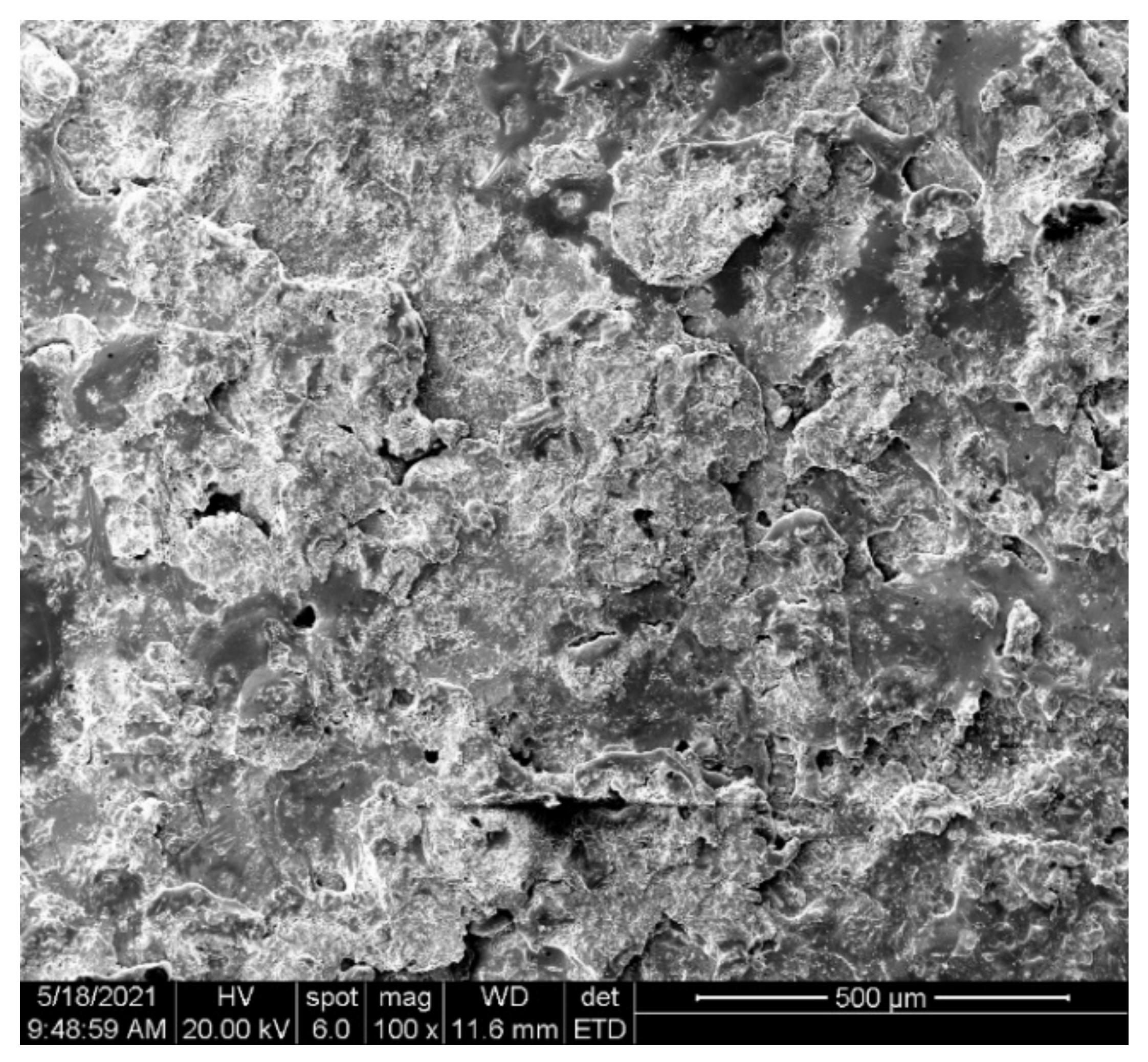
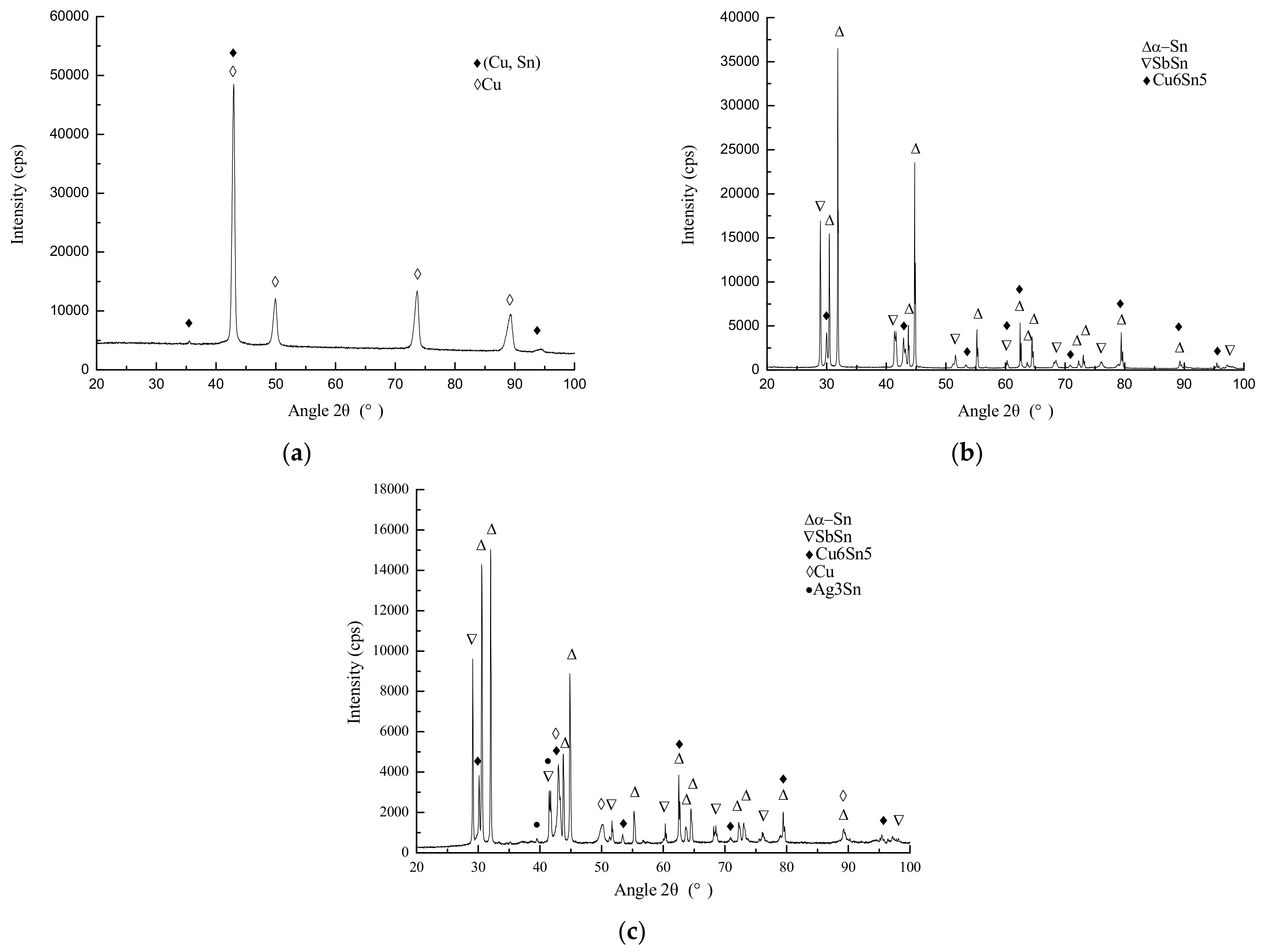
3.2. The Morphology, Element Composition, and Phase Composition of the Running-In Coating Surface

The morphology of the running-in coating surface of specimen 2 is shown in Figure 2. The surface of the running-in functional coatings deposited by the electric spark showed fused accumulation, which was formed by the gradual superposition of many irregular metal droplets melted by the electrode during pulse discharge. There were almost no micro-cracks on the surface of the soft functional coatings, and the micro-cracks easily expand along the direction perpendicular to the surface of the running-in coating. Electro-spark deposition technology caused the metal to heat and cool quickly, and the functional coating easily produced residual stress, which led to cracks. Soft metal has good plasticity, which can alleviate thermal stress, thereby reducing cracks. The multilayer structure with a low modulus ratio contributed to reducing the stress concentration in harder sub-layers, thereby inhibiting crack initiation.
After electro-spark deposition, the surface of the functional coatings can meet the technical requirements only by simple processing. The surface of the running-in functional coatings of the bearing bush of the sliding bearing is beneficial for embedding particles and storing lubricating oil, reducing the wear of particles on the surface of the bearing bush, reducing the friction force, and improving the lubricating performance [30]. There was a small amount of black material on the surface of the running-in coatings deposited by electro-spark, which was caused by the oxidation of part of the metal caused by instantaneous high temperature, and the black material should be metal oxide.
The element composition on the surface of the running-in coatings was characterized by the energy dispersion spectrum in Table 3. As can be seen in the table, with an increase in discharge energy, the content of copper and silver on the specimen’s surface gradually decreased, while the content of tin gradually increased, which also indicates that the content of Babbitt B83 on the surface of running-in coatings was increasing. However, with an increase in discharge energy, the content of antimony on the sample surface gradually decreased, possibly because high temperatures increase antimony loss.
After alloying, the surfaces were sanded with 1000 grit sandpaper, and the X-ray diffraction analysis of the running-in coating surface was carried out. Figure 3 shows the X-ray diffraction patterns of the substrate, Babbitt B83, and the running-in coating surfaces of specimen 2.
The diffraction peaks observed for the substrate surface in Figure 3a clearly indicate the phases corresponding to Cu and (Cu, Sn). The Cu phase showed strong diffraction intensity, suggesting that the content of Cu was relatively high in the substrate.
As shown in Figure 3b, the diffraction peaks for Babbitt B83′s surface clearly indicate the phases corresponding to α-Sn, SbSn, and Cu6Sn5. The α-Sn phase showed strong diffraction intensity, suggesting that the content of α-Sn was relatively high in Babbitt B83.
The diffraction peaks observed for the running-in coating surface of specimen 2 in Figure 3c clearly indicate the phases corresponding to α-Sn, SbSn, Cu6Sn5, and Cu. The α-Sn phase showed strong diffraction intensity, suggesting that the content of α-Sn was relatively high in the running-in coatings. Moreover, in the case of running-in coatings, in addition, a phase of Ag3Sn appeared, which is conducive to strengthening the metallurgical bonding between the substrate and the coating and between the coatings, and it is also conducive to grain refinement [31]. It should be noted that oxide peaks, nitride peaks, and carbide peaks were not observed. It is possible that the content of these constitutions was too low to be detected by XRD.

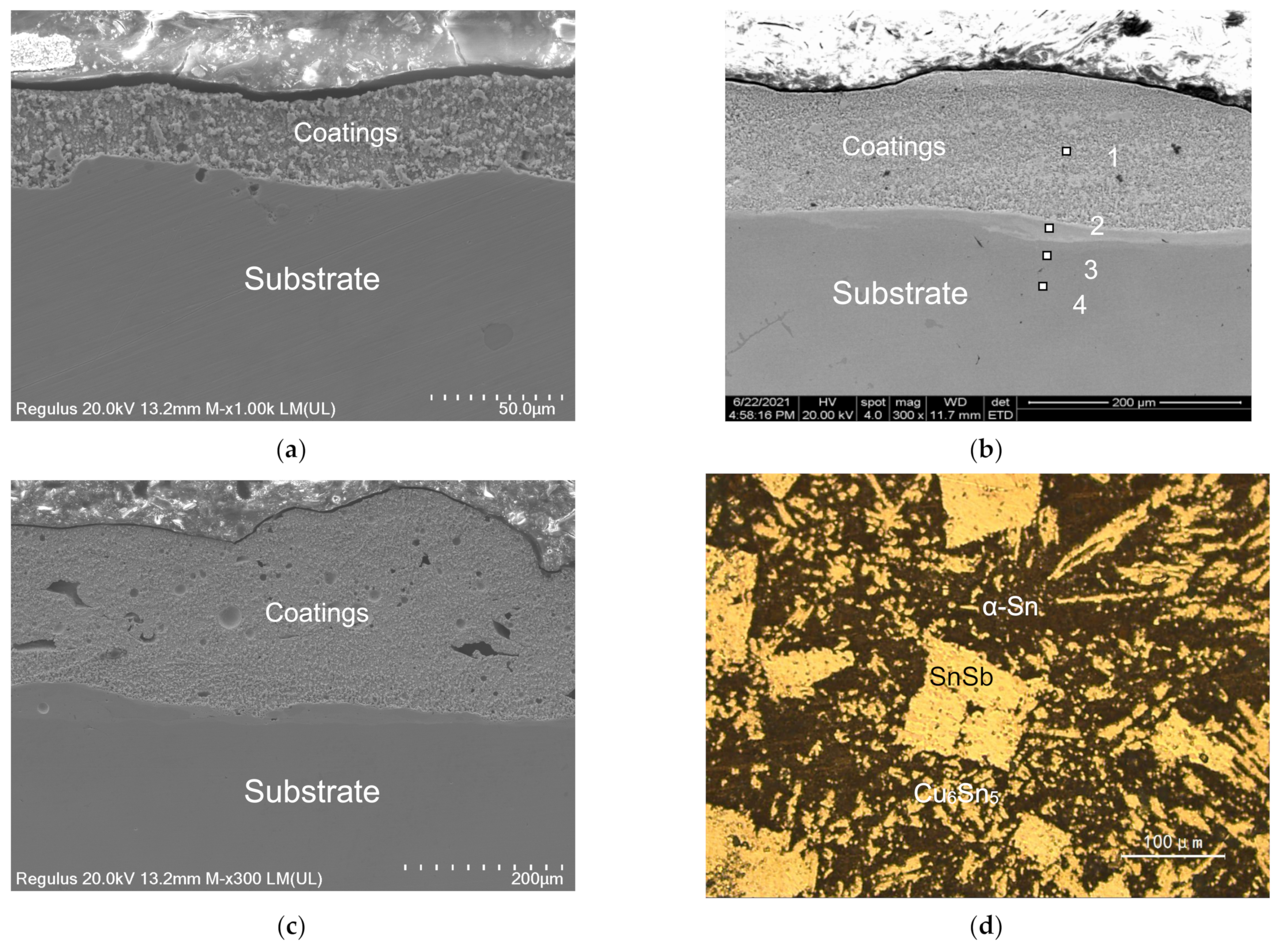
3.3. The Cross-Section Morphology of the Running-In Coatings

The cross-section morphology of the ESD-treated running-in coatings and Babbitt B83 were analyzed using scanning electron microscopy and metallographic microscopy.
Figure 4a shows the cross-section micro-morphology of specimen 1 with electro-spark deposition running-in function coatings. The cross-section image of the coatings shows that the coatings had a good metallurgical bonding with the tin bronze substrate, and the running-in functional coatings had a dense structure and fine grains, but there were a few micro-cracks and holes. The running-in coatings from the surface to the substrate were B83, GO, B83, Cu, and Ag. Because of the good wettability of silver and copper, the silver and copper coatings were almost completely fused together to form an alloy layer, which is not easy to distinguish. The thickness of the running-in coatings was only about 50 microns because the discharge energy of sample 1 was small.
Figure 4b shows the cross-sectional microtopography of the electro-spark deposited running-in functional coatings of specimen 2. As can be seen in the cross-sectional image of the sample with the electro-spark running-in coatings, it had a good metallurgical bonding with the tin bronze substrate. The microstructure of the running-in functional coatings was compact, and the grains are fine. The substrate and the coating could be clearly distinguished, but there was a small number of micro-cracks and holes. The running-in coatings deposited by electro-spark were B83, GO, B83, Cu, and Ag from the surface to the substrate. Because of the good wettability of silver and copper, the silver and copper coatings almost completely fused together to form an alloy layer, which was not easy to distinguish separately. Table 4 shows the test results of element composition at different positions of the running-in coatings section in sample 2. During the second electro-spark deposition of B83, a part of the graphene oxide on the surface was splashed off the surface along with the electro-spark. Due to the limitation of detection equipment technology, graphene oxide could not be detected because of its low content.
Figure 4c shows the cross-section microstructure of specimen 3. It can be seen in the cross-section of the sample that the coating has good metallurgical bonding with the tin bronze substrate. The microstructure of the running-in functional coatings was compact, and the grain was fine, but there were many holes. In the process of electro-spark deposition, the instantaneous high temperature produced by pulse width modulation (PWM) pulse discharge caused melting, evaporation, spattering, and alloying to occur in the discharge area. The rapid cooling and solidification of the surface after discharge lead to large cyclic thermal stress and microstructure stress in the running-in functional coatings, which leads to the emergence of micro-cracks or pores on the coating surface. In the process of electro-spark deposition, a small number of micro-cracks or pores on the surface of the functional coatings cannot be filled by the molten material, so holes are formed. Moreover, the high viscosity of the molten metal may prevent it from flowing into the valleys even if metal was ejected in its direction prior to its solidification. As a result, a void is left where the valleys once were.
Figure 4d presents the metallographic diagram of the cast electrode material Babbitt B83. It indicates that the square or rectangle with bright color is SnSb, the dark color is α-Sn, and the chain or elongated needle is Cu6Sn5. However, it can be seen in Figure 4a–c that the grains of Babbitt B83 in the electro-spark-deposited running-in coatings were very dense, refined, and uniformly distributed, which is the result of rapid heating and cooling of the antifriction materials by ESD technology [32,33].

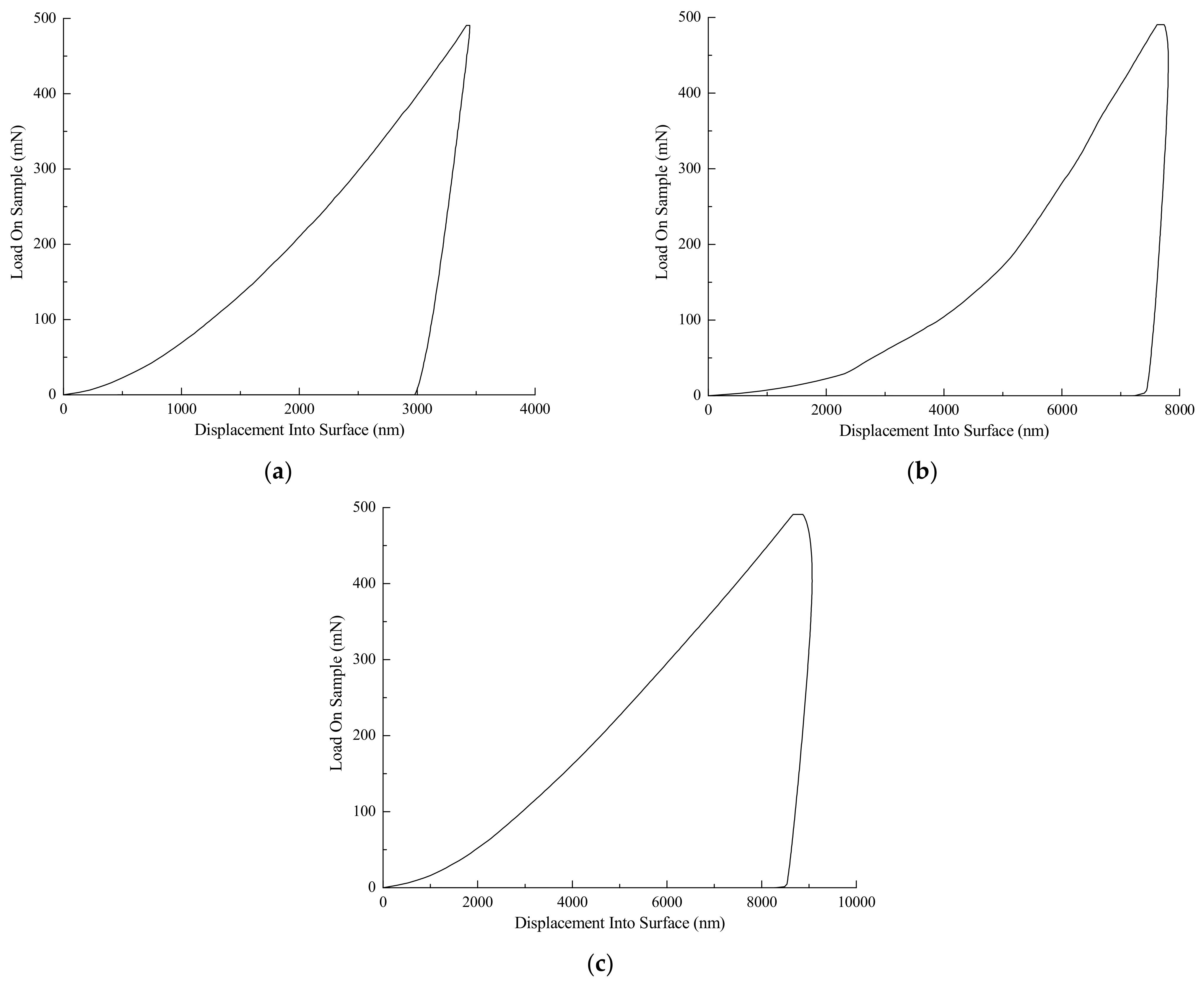
3.4. The Nanoindentation Properties of the Running-In Coatings

The electro-spark deposition technique can change the modulus, the hardness, and the deformation rate of the nanoindentation properties of the treated material.
Figure 5 shows the nanoindentation curve of the substrate, Babbitt B83, and the running-in coatings. The nanoindentation curve of the substrate is shown in Figure 5a, and the curve is the change in the displacement onto the surface with the load on the sample, which can be divided into three segments in turn: load segment type, hold segment type, and unload from peak segment type. At the maximum load on the substrate, the modulus was 77.1 GPa, the hardness was 1.93 GPa, and the displacement onto the surface was 3445.8 nm. When completely unloaded, the displacement onto the surface was 2980.1 nm, and the deformation rate of the substrate was 86.49%. The nanoindentation curve of Babbitt B83 in Figure 5b shows the change in the displacement onto the surface with the load on the sample, which can be divided into three segments: load segment type, hold segment type, and unload from peak segment type. At the maximum load on the Babbitt B83, the modulus was 52.8 GPa, the hardness was 0.352 GPa, and the displacement onto the surface was 7754.9 nm. When completely unloaded, the displacement onto the surface was 7249.2 nm, and the deformation rate of the Babbitt B83 was 93.48%. The nanoindentation curve of the running-in coatings of specimen 2 is the change in displacement onto the surface with the load on the sample, as shown in Figure 5c, which can be divided into load segment type, hold segment type, and unload from peak segment type. At the maximum load on the running-in coatings, the modulus was 19.2 GPa, the hardness was 0.281 GPa, and the displacement onto the surface was 8901.0 nm. When completely unloaded, the displacement onto the surface was 8482.9 nm, and the deformation rate of the substrate was 95.30%.
The modulus, hardness, and deformation ratio of the substrate, Babbitt B83, and running-in coatings of specimen 2 are shown in Table 5. The modulus of the running-in coatings was 36.4% for Babbitt B83 and 24.9% for the tin bronze substrate. The hardness of the running-in coatings was 79.8% for Babbitt B83 and 14.2% for the bronze substrate. The deformation ratio of the running-in coatings was 1.9% higher than that of Babbitt B83 and 10.2% higher than that of the substrate. The application of the electro-spark deposited running-in coatings led to a considerable decrease in the modulus and hardness in relation to the substrate material.

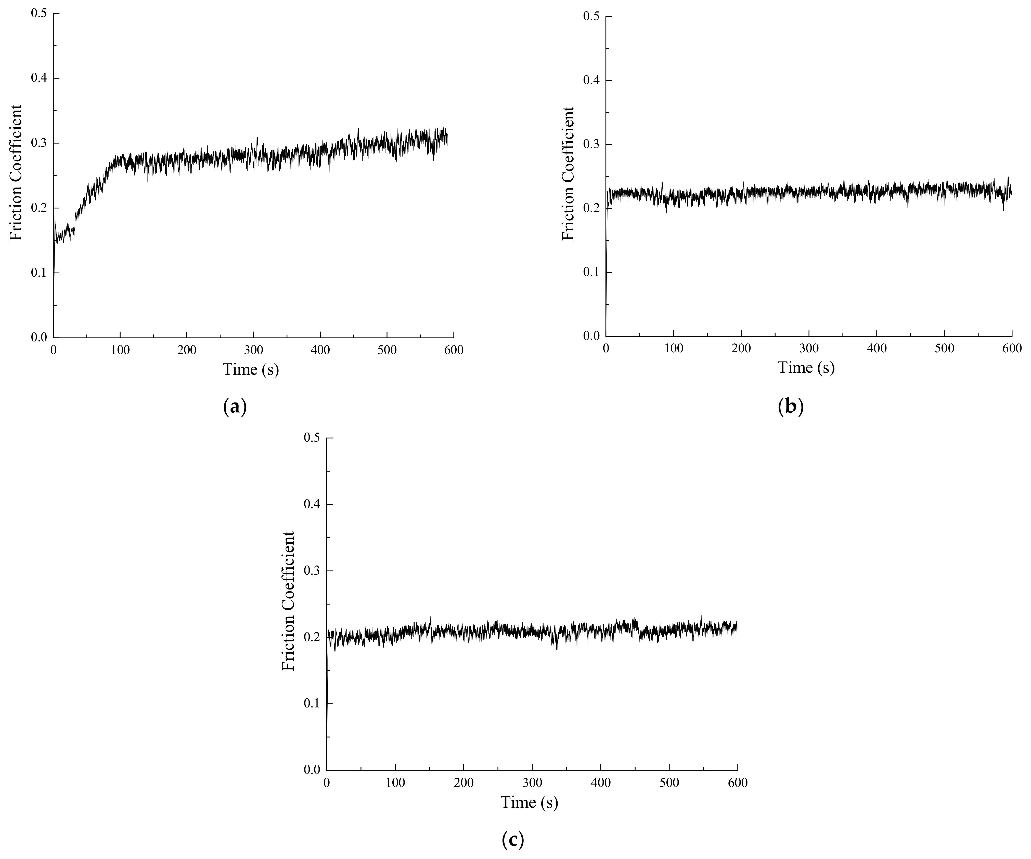
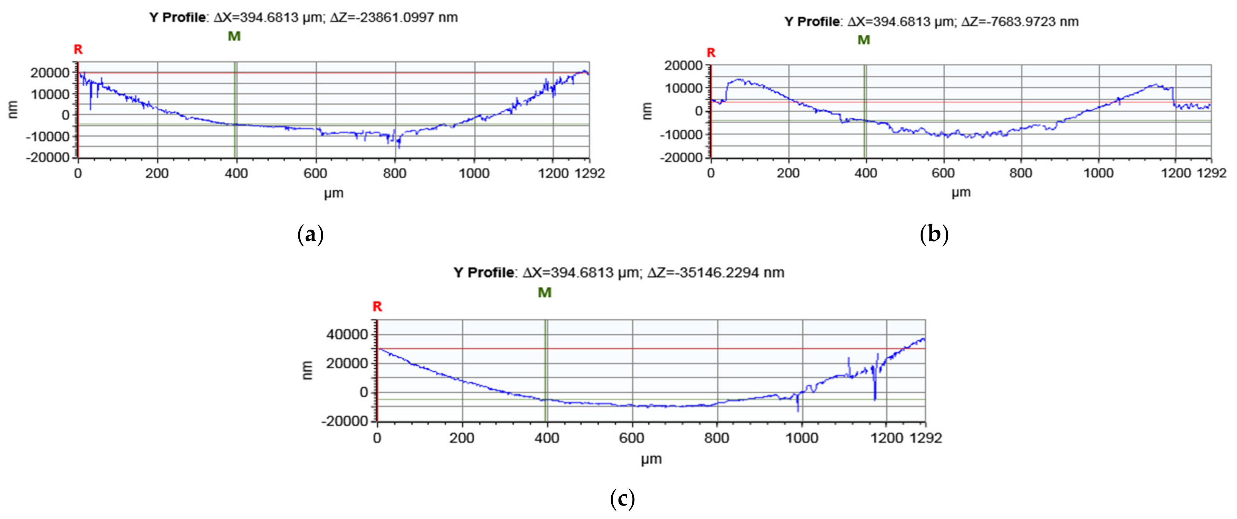
3.5. Tribological Properties of the Running-In Coatings

The tribological properties of the material’s surface can be influenced by electro-spark deposition [34,35,36].
Table 6 shows the evolution of the coefficient of friction at the applied loads of 5 N, 10 N, and 15 N of the specimens sliding against a GCr15 steel ball in the air. For the initial 600 s at a load of 5 N of the substrate, the friction coefficient had an average value of about 0.333. For the following 600 s at a load of 10 N, the friction coefficient was about 0.330. For the 15 N load in the final 600 s, the friction coefficient was about 0.324. For the initial 600 s at a load of 5 N of Babbitt B83, the friction coefficient had an average value of about 0.206. For the following 600 s at a load of 10 N, the friction coefficient was about 0.188. For the 15 N load in the final 600 s, the friction coefficient was about 0.192.
The investigation of the tribological properties of the coatings in dry friction showed that lower resistance was exhibited by the running-in coatings deposited using the antifriction material. The surface friction coefficient of specimen 1 was the minimum of the composite coatings after the running-in stage, but the value of the coating’s thickness for specimen 1 was 50 μm. Due to the small coating thickness, the bearing bush surface may be scratched when running in under different working conditions. Because the surface roughness of sample 3 was too large, the friction coefficient during running-in was too large, which affects the use effect. Considering this, the overall performance of sample 2 was the best. Therefore, specimen 2 is the best choice.
From the evolution of the coefficient of friction of the tin bronze substrate with the running-in coatings of specimen 2 in Figure 6, it is clear that the wear process indicated is rather complicated because of the influence of different surface topography and chemical composition during the running-in phase. For ESD coatings, at the beginning of the steady stage, their friction coefficient showed, to some extent, a direct response to surface roughness. Therefore, for the initial 600 s at a load of 5 N, the friction coefficient was about 0.287, influenced by the surface roughness in Figure 6a. GCr15 with high hardness produced material loss of the running-in coating’s counterpart (with relatively low hardness) through the dominant abrasion mechanism. With the generation of tribofilm, the abrasion of the running-in coatings–GCr15 sliding couples was transferred to interfacial sliding. Similar to other sliding couples, the steady-state fiction coefficients became more or less independent of the surface roughness. After the first running-in stage, the soft antifriction composite coatings demonstrated a relatively stable friction coefficient with an average value of about 0.227 after the following 600 s at a load of 10 N, as shown in Figure 6b. After the second running-in stage, Figure 6c presents the friction coefficient with an average value of about 0.210 at a load of 15 N. The friction coefficient stabilized after running-in and became stable throughout the test. After running-in, the friction coefficient of specimen 2 was 64.8% for the substrate, which was similar to that for Babbitt B83.
The surfaces of wear traces were analyzed in order to understand the friction and wear resistance mechanisms of the coatings. The wear scars of the tin bronze substrate with and without the running-in coatings after tribological testing are shown in Figure 7.
It was found in the analysis of wear scars in Figure 7a that the wear mechanism of the tin bronze substrate was dominated by severe plowing wear and fatigue delamination. A lamellar structure could be distinguished on the surface of the worn substrate. This could be responsible for the low friction under these conditions.
However, it can be seen in Figure 7b that the running-in coatings of specimen 2 may effectively restrain fatigue delamination, showing plastic deformation, scratching, and slight polishing. Plastic deformation dominated on the relatively soft antifriction coatings. The initial surface microgeometry was changed during load application, and its surface became smooth with fine shallow scratches observed after the wear test. After the smooth surface was formed, the friction and wear stabilized.
The elemental compositions of the running-in coating surfaces after tribological testing are shown in Table 7. A comparison of Table 3 and Table 7 shows that copper content on the surface of specimen 1 increased from 9.48% to 23.14%, the silver content increased from 1.54% to 2.75%, the tin content decreased from 77.21% to 54.35%, and the antimony content decreased from 16.78% to 5.89 after the friction test. This indicates that the running-in coatings on the surface of specimen 1 were too thin and failed too easily; in particular, the Babbitt alloy B83 coating was gradually removed during the running-in period, which led to the exposure of part of the copper coating and even part of the tin bronze substrate and ultimately failed to play the role of running-in coatings. In addition, oxygen elements were detected on the surface, indicating the formation of oxides after surface wear. Table 3 and Table 7 show that the contents of copper, silver, tin, and antimony on the surface of specimen 2 and specimen 3 showed little change after the friction test. This indicates that the running-in coatings on the surface of specimen 2 and specimen 3 were thick and stable. In addition, the oxygen content detected on the surface indicates that due to the poor stability of tin, the oxides were generated after surface wear.
The surface profiles of the substrate, Babbitt B83, and the running-in coatings after tribological testing are shown in Figure 8.
It was found in the analysis of the surface profile in Figure 8a that the surface of the tin bronze substrate was severely worn, and the wear depth was up to 30 μm. It can be seen in Figure 8b that Babbitt B83 was deformed on both sides by extrusion, and the wear depth was 25 μm. Figure 8c shows that the running-in coatings of specimen 2 deformed in the direction of the extrusion force, and the wear deformation depth reached 40 μm.
The facilitation of running-in conditions and the improvement in the friction surface operating regime in the post-running-in period were provided by improving the bearing bush by applying the composite coatings by ESD. The running-in coating deformation under the action of high specific loads provides automatic adjustment and compensation for manufacturing errors.

4. Conclusions

On the basis of the obtained test results and their interpretation, the following conclusions can be drawn:
(1)
The running-in coatings of silver, copper, Babbitt B83, and graphene oxide were deposited on the tin bronze QSn10-1 by electro-spark deposition. At optimum process parameters, the mass transfer was 244.2 mg, the surface roughness of the composite coatings was 15.9 μm, and the thickness was 160 μm. The diffraction peaks observed for the running-in coating surface clearly indicated the phases corresponding to α-Sn, SbSn, Cu6Sn5, and Cu, and a phase of Ag3Sn appeared, which is conducive to strengthening the metallurgical bonding as well as grain refinement.
(2)
The grains in the running-in coatings were very dense, refined, uniformly distributed by ESD technology, and in a metallurgical bond state with the tin bronze substrate.
(3)
The modulus of the running-in coatings was 36.4% for Babbitt B83 and 24.9% for the tin bronze substrate. The hardness of the running-in coatings was 79.8% for Babbitt B83 and 14.2% for the bronze substrate. The deformation ratio of the running-in coatings was 1.9% higher than that of Babbitt B83 and 10.2% higher than that of the substrate.
(4)
The friction coefficient stabilized after running-in and became stable during the test. The friction coefficient of the running-in coatings (0.210) was 64.8% for the substrate (0.324), which was similar to that of Babbitt B83 (0.192). The wear mechanism of the running-in coatings was dominated by plastic deformation, scratching, and slight polishing. The running-in coating deformation under the action of high specific loads provides automatic adjustment of parts and compensation for manufacturing errors.

Author Contributions

Conceptualization, V.T. and I.K.; methodology, I.K.; software, Z.Z.; validation, G.L., X.D. and H.Y.; formal analysis, Z.Z.; investigation, Z.Z.; resources, G.L. and H.Y.; data curation, X.D.; writing—original draft preparation, Z.Z.; writing—review and editing, I.K.; visualization, Z.Z.; supervision, V.T.; project administration, I.K.; funding acquisition, V.T. All authors have read and agreed to the published version of the manuscript.

Funding

This research was funded by the Ministry of Education and Science of Ukraine, grant number 0116U002756.

Institutional Review Board Statement

Not applicable.

Informed Consent Statement

Not applicable.

Data Availability Statement

Data sharing is not applicable to this article.

Acknowledgments

The materials for experiments were provided by Zhejiang Shenfa Bearing Co., Ltd. (Zhuji, China).

Conflicts of Interest

The authors declare no conflict of interest. The funders had no role in the design of the study; in the collection, analyses, or interpretation of data; in the writing of the manuscript; or in the decision to publish the results.

References

  1. Philip, J.T.; Kumar, D.; Mathew, J.; Kuriachen, B. Tribological investigations of wear resistant layers developed through EDA and WEDA techniques on Ti6Al4V surfaces: Part II—High temperature. Wear 2021, 466, 203540–203551. [Google Scholar] [CrossRef]
  2. Chen, S.; Wei, L.; Cheng, B.X.; Jin, Y.L.; Li, C.; Jia, D.; Duan, H.T. Dry sliding tribological properties of PI/UHMWPE blends for high speed application. Tribol. Int. 2020, 146, 106262–106276. [Google Scholar] [CrossRef]
  3. Tang, Y.C.; Wan, N.; Shen, M.X.; Jiao, H.T.; Liu, D.J.; Tang, X.C.; Zhao, L.Z. A comparison of the microstructures and hardness values of non-equiatomic (FeNiCo)-(AlCrSiTi) high entropy alloys having thermal histories related to laser direct metal deposition or vacuum remelting. J. Mater. Res. Technol. 2021, 15, 696–707. [Google Scholar] [CrossRef]
  4. Kobernik, N.V.; Mikheev, R.S.; Brzhezinskaya, M.; Aleshin, N.P. Effect of carbon nanotubes on structure and properties of the antifriction coatings produced by plasma cladding. Fuller. Nanotub. Carbon Nanostruct. 2020, 28, 515–520. [Google Scholar] [CrossRef]
  5. Wang, D.; Gao, J.H.; Deng, S.J.; Wang, W.Q. A novel particle planting process based on electrospark deposition. Mater. Lett. 2022, 306, 130872–130886. [Google Scholar] [CrossRef]
  6. Radek, N.; Konstanty, J.; Pietraszek, J.; Orman, L.J.; Szczepaniak, M.; Przestacki, D. The effect of laser beam processing on the properties of WC-Co coatings deposited on steel. Materials 2021, 14, 538–550. [Google Scholar] [CrossRef]
  7. Shafudah, N.H.; Nagai, H.; Suwazono, Y.; Ozawa, R.; Kudoh, Y.; Takahashi, T.; Onuma, T.; Sato, M. Hydrophilic titania thin films from a molecular precursor film formed via electrospray deposition on a quartz glass substrate precoated with carbon nanotubes. Coatings 2020, 10, 1050–1063. [Google Scholar] [CrossRef]
  8. Cao, J.; Huang, H.B.; Li, S.X.; Wu, X.C.; Yin, Z.W.; Abbas, Z. Tribological and mechanical behaviors of engine bearing with CuSn10 layer and h-BN/graphite coating prepared by spraying under different temperatures. Tribol. Int. 2020, 152, 106445–106456. [Google Scholar] [CrossRef]
  9. Dinesh, D.; Megalingam, A. Dry sliding friction and wear behaviour of leaded tin bronze for bearing and bushing application. Arch. Metall. Mater. 2021, 66, 1095–1104. [Google Scholar] [CrossRef]
  10. Ribeiro, R.M.; Camara, M.A. Study of the tribological behavior of the Babbitt alloy—Steel ABNT 1045 pair when varied thickness and roughness of the coating. Materia 2020, 25, 1061–1075. [Google Scholar] [CrossRef]
  11. Dyachkova, L.N. Tribological characteristics and wear features of powder tin bronze with the addition of ultrafine oxides. J. Frict. Wear 2020, 41, 295–299. [Google Scholar] [CrossRef]
  12. Bazhenov, V.E.; Titov, A.Y.; Shkalei, I.V.; Sannikov, A.V.; Nikitina, A.A.; Plisetskaya, I.V.; Bazlov, A.I.; Mezrin, A.M.; Koltygin, A.V. Effect of the cooling rate on the microstructure and properties of C92900 bronze. Russ. J. Non-Ferr. Met. 2021, 62, 274–285. [Google Scholar] [CrossRef]
  13. Ren, X.Y.; Zhang, G.W.; Xu, H.; Wang, Z.J.; Liu, Y.J.; Sun, F.E.; Kang, Y.Y.; Wang, M.J.; Lv, W.Z.; Yin, Z. Effects of B on the structure and properties of Lead-Tin bronze alloy and the mechanism of strengthening and toughening. Materials 2021, 14, 7806. [Google Scholar] [CrossRef]
  14. Gajmal, S.S.; Raut, D.N. An investigation on wear behaviour of ASTM B23 Tin-Based Babbitt alloy developed through microwave-assisted casting. Int. J. Metalcast. 2022, 1, 1–19. [Google Scholar] [CrossRef]
  15. Kamal, M.; El-Bediwi, A.; Lashin, A.R.; El-Zarka, A.H. Copper effects in mechanical properties of rapidly solidified Sn-Pb-Sb Babbitt bearing alloys. Mater. Sci. Eng. A-Struct. 2011, 530, 327–332. [Google Scholar] [CrossRef]
  16. Dong, Q.; Yin, Z.W.; Li, H.L.; Gao, G.Y.; Zhong, N.; Chen, Y.H. Simulation and experimental verification of fatigue strength evaluation of journal bearing bush. Eng. Fail. Anal. 2020, 109, 104275–104286. [Google Scholar] [CrossRef]
  17. Ni, Y.Q.; Li, X.; Dong, G.N.; Tong, Z.; Mei, T.J. The combined effect of La and heat treatment on the tribological performances of tin-Babbitt alloy. Proc. Inst. Mech. Eng. Part J J. Eng. Tribol. 2019, 233, 1117–1126. [Google Scholar] [CrossRef]
  18. Ni, Y.Q.; Dong, G.N.; Tong, Z.; Li, X.; Wang, W. Effect of laser remelting on tribological properties of Babbitt alloy. Mater. Res. Express 2019, 6, 096570. [Google Scholar] [CrossRef]
  19. Choi, J.; Okimura, N.; Yamada, T.; Hirata, Y.; Ohtake, N.; Akasaka, H. Deposition of Graphene–Copper composite film by cold spray from particles with graphene grown on copper particles. Diam. Relat. Mater. 2021, 116, 108384–108396. [Google Scholar] [CrossRef]
  20. Zhang, Z.G.; Lu, X.T.; Xu, J.R.; Luo, H.J. Characterization and tribological properties of Graphene/Copper composites fabricated by electroless plating and powder metallurgy. Acta Met. Sin. Engl. 2020, 33, 903–912. [Google Scholar] [CrossRef]
  21. Wang, L.; Gong, P.W.; Li, W.; Luo, T.; Cao, B.Q. Mono-dispersed Ag/Graphene nanocomposite as lubricant additive to reduce friction and wear. Tribol. Int. 2020, 146, 106228. [Google Scholar] [CrossRef]
  22. Wu, F.; Zhao, W.J.; Chen, H.; Zeng, Z.X.; Wu, X.D.; Xue, Q.J. Interfacial structure and tribological behaviours of epoxy resin coating reinforced with graphene and graphene oxide. Surf. Interface Anal. 2017, 49, 85–92. [Google Scholar] [CrossRef]
  23. Guler, O.; Bagci, N. A short review on mechanical properties of graphene reinforced metal matrix composites. J. Mater. Res. Technol. 2020, 9, 6808–6833. [Google Scholar] [CrossRef]
  24. Song, W.; Chen, P.; Yan, J.C.; Zhu, W.S.; Ji, H.B. The tribological properties of reduced graphene oxide doped by N and B species with different configurations. ACS Appl. Mater. Interfaces 2020, 12, 29737–29746. [Google Scholar] [CrossRef] [PubMed]
  25. Sheveyko, A.N.; Kuptsov, K.A.; Kiryukhantsev-Korneev, P.V.; Kaplansky, Y.Y.; Orekhov, A.S.; Levashov, E.A. Protective coatings for LPBF Ni-based superalloys using a combination of electrospark deposition and pulsed arc evaporation methods. Appl. Surf. Sci. 2022, 581, 152357–152369. [Google Scholar] [CrossRef]
  26. Khan, M.S.; Enrique, P.; Ghatei-Kalashami, A.; Lopes, J.G.; Schell, N.; Oliveira, J.P.; Biro, E.; Zhou, Y.N. The influence of in-situ alloying of electro-spark deposited coatings on the multiscale morphological and mechanical properties of laser welded Al-Si coated 22MnB5. Mater. Sci. Eng. A-Struct. 2022, 839, 142830–142839. [Google Scholar] [CrossRef]
  27. Liang, Z.; Zhang, H.; Wang, S.; Zhang, L.; Zhu, C.; Jin, H.; Guo, C. Comparative research of electrospark deposited Tungsten alloy coating in two kinds of gas. Dig. J. Nanomater. Bios. 2021, 16, 793–800. [Google Scholar]
  28. Wang, X.R.; Wang, Z.Q.; Lin, T.S.; He, P. Mass transfer trends of A1CoCrFeNi high-entropy alloy coatings on TC11 substrate via electrospark—Computer numerical control deposition. J. Mater. Process. Technol. 2017, 241, 93–102. [Google Scholar] [CrossRef]
  29. Korkmaz, K.; Ribalko, A.V. Effect of pulse shape and energy on the surface roughness and mass transfer in the electrospark coating process. Kov. Mater. 2011, 49, 265–270. [Google Scholar] [CrossRef]
  30. Xue, Y.W.; Shi, X.L.; Zhou, H.Y.; Yang, Z.Y.; Zhang, J.; Wu, C.H.; Xue, B. Effects of textured surface combined with Sn-Ag-Cu coating on tribological properties and friction-induced noise of Ti-6Al-4V alloy. Tribol. Trans. 2021, 64, 562–577. [Google Scholar] [CrossRef]
  31. Dong, Q.; Yin, Z.W.; Li, H.L.; Zhang, X.Y.; Jiang, D.; Zhong, N. Effects of Ag micro-addition on structure and mechanical properties of Sn-11Sb-6Cu Babbitt. Mater. Sci. Eng. A-Struct. 2018, 722, 225–230. [Google Scholar] [CrossRef]
  32. Kuptsov, K.A.; Sheveyko, A.N.; Manakova, O.S.; Sidorenko, D.A.; Shtansky, D.V. Comparative investigation of single-layer and multilayer Nb-doped TiC coatings deposited by pulsed vacuum deposition techniques. Surf. Coat. Technol. 2020, 385, 125422. [Google Scholar] [CrossRef]
  33. Zhao, H.; Gao, C.; Wu, X.Y.; Xu, B.; Lu, Y.J.; Zhu, L.K. A novel method to fabricate composite coatings via ultrasonic-assisted electro-spark powder deposition. Ceram. Int. 2019, 45, 22528–22537. [Google Scholar] [CrossRef]
  34. Zhang, Y.; Li, L.; Wang, X.M.; Zhao, Y.; Chang, Q.; Wang, W.Y.; Xu, A.Y. Experimental study on aluminum bronze coating fabricated by electro-spark deposition with subsequent ultrasonic surface rolling. Surf. Coat. Technol. 2021, 426, 127772–127783. [Google Scholar] [CrossRef]
  35. Kuptsov, K.A.; Antonyuk, M.N.; Bondarev, A.V.; Sheveyko, A.N.; Shtansky, D.V. Electrospark deposition of wear and corrosion resistant Ta(Zr)C-(Fe,Mo,Ni) coatings to protect stainless steel from tribocorrosion in seawater. Wear 2021, 486, 204094–204104. [Google Scholar] [CrossRef]
  36. Holubets, V.M.; Pashechko, M.I.; Borc, J.; Tisov, O.V.; Shpuliar, Y.S. Wear resistance of electrospark-deposited coatings in dry sliding friction conditions. Powder Metall. Met. Ceram. 2021, 60, 90–96. [Google Scholar] [CrossRef]
Figure 1. The surface topography and profile of the running-in coatings of specimen 2: (a) the surface topography; (b) X profile; (c) Y profile.
Coatings 12 00930 g001
Figure 2. The morphology of the running-in coating surface of specimen 2.
Coatings 12 00930 g002
Figure 3. The X-ray diffraction patterns: (a) the substrate; (b) Babbitt B83; (c) the running-in coatings of specimen 2.
Coatings 12 00930 g003
Figure 4. The cross-section morphology: (a) the running-in coatings of specimen 1; (b) the running-in coatings of specimen 2, 1—research area 1, 2—research area 2, 3—research area 3, 4—research area 4; (c) the running-in coatings of specimen 3; (d) Babbitt B83.
Coatings 12 00930 g004
Figure 5. The nanoindentation curve: (a) the substrate; (b) Babbitt B83; (c) the running-in coatings of specimen 2.
Coatings 12 00930 g005
Figure 6. Friction coefficient variation during the running-in coating tests of specimen 2: (a) loads of 5 N; (b) loads of 10 N; (c) loads of 15 N.
Coatings 12 00930 g006
Figure 7. The wear scars of the tin bronze substrate with and without the running-in coatings after tribological testing: (a) the tin bronze substrate; (b) the tin bronze with the running-in coatings of specimen 2.
Coatings 12 00930 g007
Figure 8. The surface profiles of the substrate, Babbitt B83, and the running-in coatings after tribological testing: (a) the tin bronze substrate; (b) Babbitt B83; (c) the running-in coatings of specimen 2.
Coatings 12 00930 g008
Table 1. The electro-spark deposition parameters of the running-in coatings.
SpecimensCoatingsVoltage (V)Capacitance (μF)Efficiency (min/cm2)
1Ag + Cu + B83 +
GO + B83
60/40/30
--/20
90/90/30
--/30
2/1/1
--/2
2Ag + Cu + B83 +
GO + B83
60/40/30
--/25
150/90/30
--/90
2/1/1
--/2
3Ag + Cu + B83 +
GO + B83
60/40/30
--/30
150/150/90
--/150
2/1/1
--/2
Table 2. The mass transfer, roughness, and thickness characteristics of the running-in coatings.
SpecimensCoatingsMass Transfer (mg)Roughness Ra (μm)Thickness (μm)
1Ag + Cu + B83 +
GO + B83
90.8 ± 10.417.5 ± 5.550 ± 15
2Ag + Cu + B83 +
GO + B83
244.2 ± 23.315.9 ± 3.9160 ± 60
3Ag + Cu + B83 +
GO + B83
550.1 ± 78.024.6 ± 7.1200 ± 125
Table 3. The elemental composition of the running-in coating surface.
SpecimensCu (Weight %)Ag (Weight %)Sn (Weight %)Sb (Weight %)
19.48 ± 0.101.54 ± 0.1077.21 ± 0.1016.78 ± 0.10
27.08 ± 0.101.51 ± 0.1077.01 ± 0.1014.41 ± 0.10
37.09 ± 0.100.52 ± 0.1083.32 ± 0.109.08 ± 0.10
Table 4. The cross-section elemental composition of the running-in coatings of specimen 2.
Research AreaCu (Weight%)Ag (Weight%)Sn (Weight%)Sb (Weight%)
16.49 ± 0.10082.95 ± 0.1010.56 ± 0.10
264.76 ± 0.1013.97 ± 0.1017.53 ± 0.103.74 ± 0.10
355.82 ± 0.1040.28 ± 0.103.90 ± 0.100
491.03 ± 0.108.97 ± 0.100
Table 5. The modulus, hardness, and deformation ratios of the substrate, Babbitt B83, and the running-in coatings of specimen 2.
SpecimensModulus (GPa)Hardness (GPa)Deformation Ratio (%)
substrate77.1 ± 16.11.983 ± 0.28786.49
B8352.8 ± 14.30.352 ± 0.22493.48
coatings19.2 ± 8.80.281 ± 0.06195.30
Table 6. The friction coefficients during the substrate, Babbitt B83, and running-in coating tests at loads of 5 N, 10 N, and 15 N.
Specimens5 N10 N15 N
substrate0.333 ± 0.0510.330 ± 0.0320.324 ± 0.034
B830.206 ± 0.0220.188 ± 0.0170.192 ± 0.021
10.265 ± 0.0210.175 ± 0.0150.208 ± 0.019
20.287 ± 0.0320.227 ± 0.0170.210 ± 0.018
30.374 ± 0.0300.326 ± 0.0280.217 ± 0.020
Table 7. The elemental composition of the running-in coating surface after tribological testing.
SpecimensO (Weight %)Cu (Weight %)Ag (Weight %)Sn (Weight %)Sb (Weight %)
113.88 ± 0.1023.14 ± 0.102.75 ± 0.1054.35 ± 0.105.89 ± 0.10
222.10 ± 0.106.07 ± 0.10062.04 ± 0.109.78 ± 0.10
312.77 ± 0.104.54 ± 0.10071.21 ± 0.1011.49 ± 0.10
Publisher’s Note: MDPI stays neutral with regard to jurisdictional claims in published maps and institutional affiliations.

