Article

Analysis of the Causes of Differences between the Upper and Lower Surfaces of Electroless Ni–P Coating on LZ91 Magnesium–Lithium Alloy

1
School of Manufacturing Science and Engineering, Southwest University of Science and Technology, Mianyang 621010, China
2
Engineering Training Center, Southwest University of Science and Technology, Mianyang 621010, China
*
Author to whom correspondence should be addressed.
These authors contributed equally to this work.
Coatings 2022, 12(8), 1157; https://doi.org/10.3390/coatings12081157
Submission received: 14 July 2022 / Revised: 5 August 2022 / Accepted: 8 August 2022 / Published: 10 August 2022

Abstract

:
To address the issue of poor corrosion resistance of the Mg–Li alloy, electroless Ni–P plating was used to create a protective coating. However, there were significant differences between the upper and lower surface coatings, which were summarized as follows: (1) compared with the lower surface, the longitudinal differences between different areas of the upper surface coating were larger; and (2) the denseness of the upper surface coating was insufficient in areas where the insoluble phase was concentrated, resulting in significantly lower corrosion resistance of the upper surface coating than the lower surface. Resolving these differences could compensate for the defects of the upper surface coating so as to improve the overall corrosion resistance of the material. Therefore, in this paper, the deposition process of Ni–P was observed and speculated, and the reasons for these differences were analyzed in combination with experimental phenomena. Based on these, two optimization measures were proposed. The SEM observation results showed that the differences between the upper and lower surface coatings were significantly reduced after optimization. The results of potentiodynamic polarization tests and EIS tests showed that the optimized upper surface coating had good corrosion resistance similar to the lower surface coating.

1. Introduction

Magnesium–lithium alloys, as ultra-light metallic structural materials, have many outstanding advantages, such as low density, high specific strength, strong shock resistance, excellent castability, etc. [1,2,3]. Due to their great weight reduction potential, magnesium–lithium alloys are widely used in telecommunications, aerospace, automotives and other fields [4,5,6]. However, the poor corrosion resistance of Mg–Li alloys limits their wider industrial application [7,8]. One of the most effective ways to improve corrosion resistance is to create protective coatings on the surfaces of alloys [9,10,11,12]. Therefore, it is particularly important to create protective coatings with excellent corrosion resistance on the surface of Mg–Li alloys. For the surface protection technology of Mg–Li alloys, many methods have been developed, such as micro-arc oxidation, chemical conversion film, anodic oxidation, electroless plating, etc. [13,14,15,16,17]. Table 1 lists a comparison of the corrosion resistance of the above surface protection technologies. As can be seen from Table 1, the electroless Ni–P coating has a more positive corrosion potential, a lower corrosion current density and a higher charge transfer resistance. It indicates that it has good corrosion resistance. Besides this, the Ni–P coating also has the advantage of uniform deposition, which can better complete the surface protection of the Mg–Li alloy substrate [18]. Although the Ni–P coating may cause a change in the magnetic properties of the material, this change is so small as to be negligible [19].
Therefore, in this study, the electroless plating method was chosen to prepare the Ni–P protective coating on the surface of the Mg–Li alloy. However, this paper found that there were significant differences between the upper and lower surfaces during electroless Ni–P plating of the Mg–Li alloys. The details were as follows: (1) compared with the lower surface, the longitudinal differences between different areas of the upper surface coating were larger; and (2) the denseness of the upper surface coating was insufficient in areas where the insoluble phase was concentrated, resulting in significantly lower corrosion resistance of the upper surface coating than the lower surface. In order to achieve adequate protection of the substrate, in this study, first the surface chemical composition and valence states of the activated substrate were evaluated by X-ray photoelectron spectroscopy. Then, the process of electroless Ni–P plating on Mg–Li alloy was deduced by observing the evolution of the microscopic morphology of Ni–P coatings. Immediately afterwards, the reasons for the significant differences between the upper and lower surface coatings were analyzed based on the deposition process and experimental phenomena. Based on these, we proposed two suitable optimization schemes: (1) preheat the substrate to the same temperature as the coating solution before electroless plating; and (2) place a baffle in parallel 1 mm above the substrate during electroless plating. Finally, the results of the potentiodynamic polarization tests and the EIS tests showed that both the optimized upper and lower surface coatings have good corrosion resistance. The adhesion test results showed that the coating had good adhesion to the substrate.

2. Materials and Methods

2.1. Material Preparation

The materials used in this study were LZ91 magnesium–lithium alloys, which were cut into rectangular blocks with a size of 20 × 10 × 5 mm3 as the substrate. The chemical compositions of the alloy were 9.27 Li, 0.85 Zn, 0.26 Al and Mg balance (in wt%). The substrates were sequentially polished with 500 grit, 1000 grit and 2000 grit abrasive papers and 1.5 μm diamond paste to ensure a uniform surface. Then, the samples were ultrasonically cleaned with acetone and deionized water for 10 min each, and finally dried naturally in the atmosphere.

2.2. Coating Preparation

The preparation process of Ni–P coating included the following steps: alkaline degreasing; acid etching; activation; and electroless Ni–P plating. First of all, the substrate was immersed in an alkaline degreasing solution for 10 min at 343.15 K, followed by acid pickling in 60 mL/L phosphoric acid and 20 mL/L nitric acid solution at 295.15 K for 20 s. Immediately after, an activation treatment was carried out in 100 g/L ammonium hydrogen fluoride and 20 mL/L nitric acid solution at 295.15 K for 10 min. A final electroless Ni–P plating was carried out. The substrate was ultrasonically cleaned with deionized water between each step. The composition and conditions of the electroless Ni–P plating bath for magnesium–lithium alloys are shown in Table 2. During the electroless plating process, the sample was suspended horizontally in the plating solution using a plastic tie wire as shown in Figure 1.

2.3. Performance and Characterization

The morphologies of different samples were observed with a scanning electron microscope JSM-6360LV (SEM, JEOL, Tokyo, Japan) and a scanning electron microscope Sigma 300 (SEM, Carl Zeiss, Oberkochen, Germany). The composition of the coating was analyzed with an energy spectrometer X-MAXN20 (Oxford Instruments, Oxford, UK).
The chemical composition of the coating was investigated using an ESCALAB Xi+ X-ray photoelectron spectrometer (XPS, ThermoFischer, Waltham, MA, USA) with an Al Kα (1486.6 eV) monochromatic source. The energy calibration was performed by adjusting the 1s peak of adventitious carbon to 284.8 eV.
Potentiodynamic polarization tests of samples were performed by an electrochemical workstation PGSTAT 302N (Eco Chemie BV, Tilburg, The Netherlands). A three-electrode configuration was used, with a saturated calomel electrode (SCE) as a reference electrode, a platinum sheet as a reference electrode and the sample as a working electrode. The samples were embedded in epoxy resin, leaving only a surface area of 10 × 10 mm2 as the effective working electrode. The corrosive medium was 3.5 wt% NaCl solution. The scanning circuit range was set at −500 mV cathodic and +900 mV anodic with respect to the open circuit potential. The sweeping rate was 1 mV/s and was done at 298.15 K. Electrochemical impedance spectroscopy (EIS) tests were performed in the frequency range from 100 kHz to 0.01 Hz with an AC potential perturbation of 5 mV. All samples had been immersed in 3.5 wt% NaCl solution for 30 min prior to all impedance tests [20,21].
The coating adhesion was tested by an MFT-4000 automatic scratch tester (Lanzhou, Huahui, China). The test conditions were 0–80 N increasing load and the scratch length was 5 mm.

3. Results

3.1. Microscopic Morphology and Composition Analysis

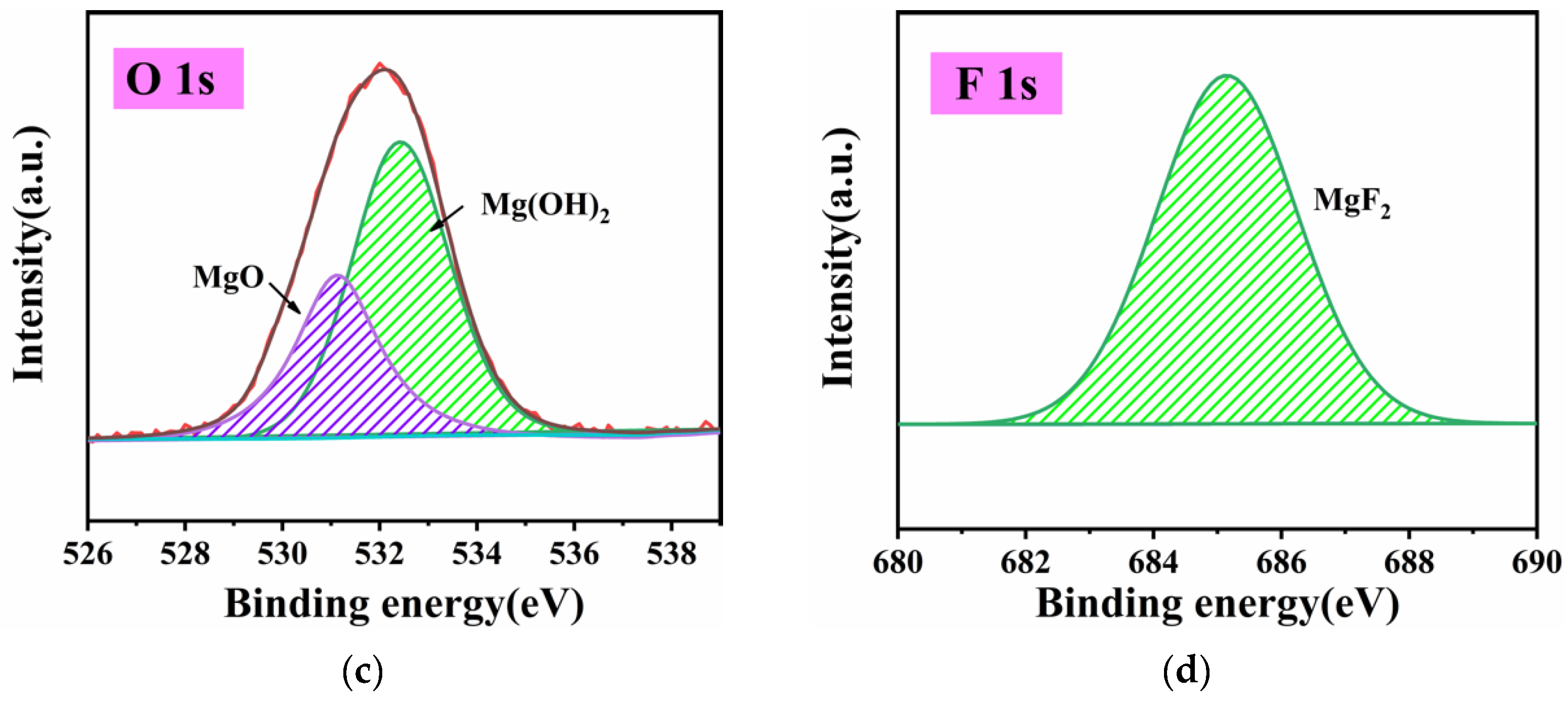
3.1.1. Analysis of Surface Composition after Activation

The surface of the activated Mg–Li alloy was detected by XPS. The chemical state and possible substances on the sample surface were judged according to the characteristic binding energies of different elements. Figure 2a shows the XPS survey spectra on the surface of the sample, which can be found to be composed mainly of C, O, F and Mg elements. The XPS spectra of Mg 1s core level regions are shown in Figure 2b, and the fitting results show that the peaks at 1302.9 eV, 1303.7 eV, and 1304.6 eV correspond to Mg(OH)2, MgO and MgF2, respectively [22,23]. The XPS spectra of the O 1s core level regions are seen in Figure 2c. The diffraction peaks at 530.9 eV and 532.4 eV were attributed to MgO and Mg(OH)2 [24,25,26], respectively, which further confirmed the formation of the above substances. Figure 2d shows the XPS spectra of F 1s core level regions. The binding energy at 685.3 eV was attributed to MgF2, which, together with Figure 2b, illustrated the existence of MgF2.
In summary, it can be shown that the main components of the activated sample surface were Mg(OH)2, MgO and MgF2. Since MgO and Mg(OH)2 were easily soluble in the ammonium salt solution and the plating solution contained ammonium salt, they took the lead in dissolving in the plating solution, and the reaction equation is shown in Equations (1) and (2) in Section 3.2. MgF2 was chemically stable, and its main function was to separate the plating solution from the substrate and prevent the plating solution from corroding the substrate excessively.
In view of the above, we inferred that at the initial stage of the reaction, MgO and Mg(OH)2 constituted the easily soluble phase, while MgF2 constituted the insoluble phase.

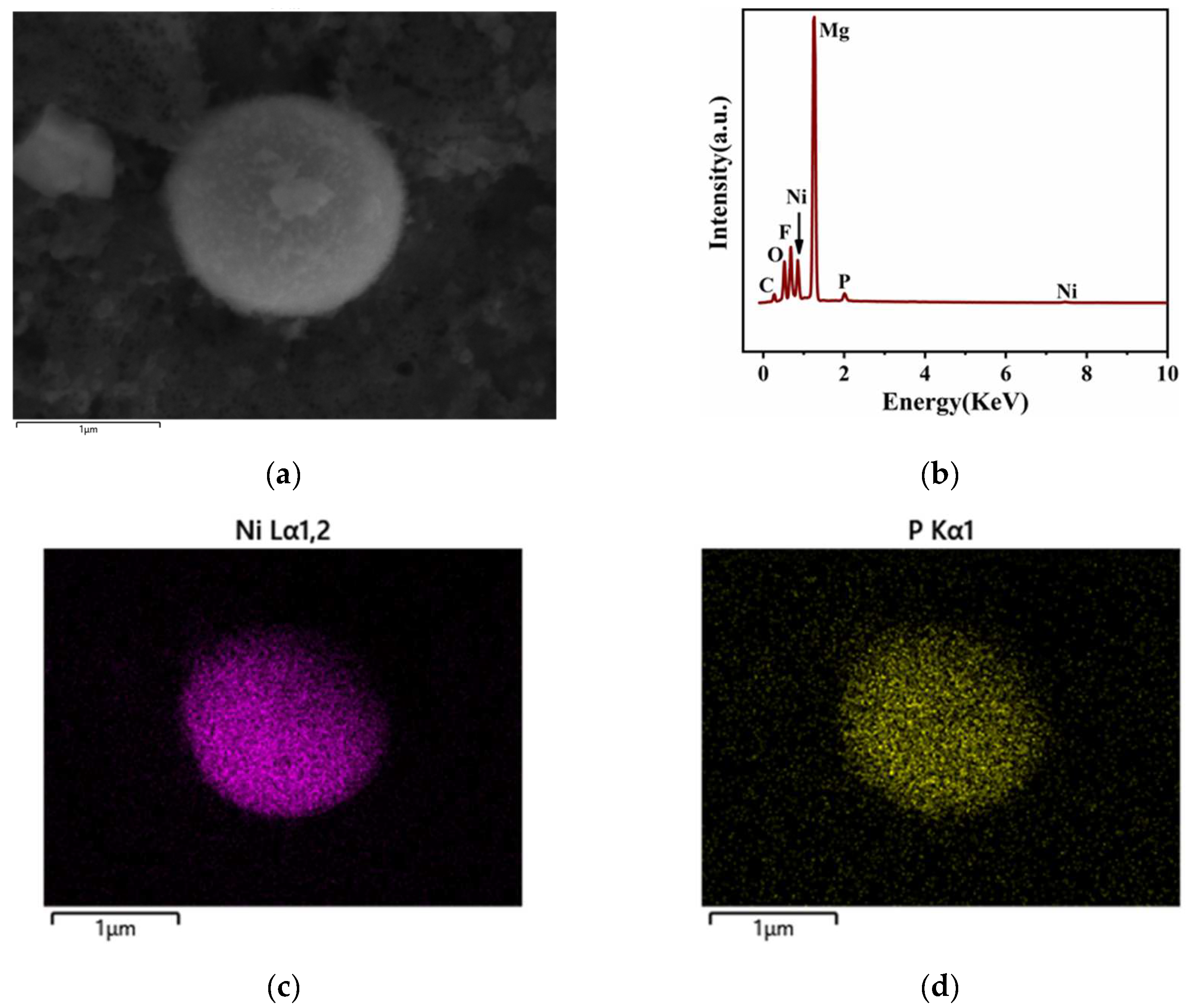
3.1.2. Analysis of Surface Composition at the Initial Stage of the Reaction

Figure 3a shows the surface morphology images of the Mg–Li alloy at 2 min into the deposition reaction. It was found that small white particles were produced on the sample surface at this time, which were analyzed by EDS, and the results are shown in Figure 3b. It can be clearly observed that Ni peaks and P peaks appeared on the surface. Then, combined with the elemental mapping of the sample surface shown in Figure 3c,d, it can be judged that the white particles produced on the surface of the sample at the initial stage were Ni–P particles.

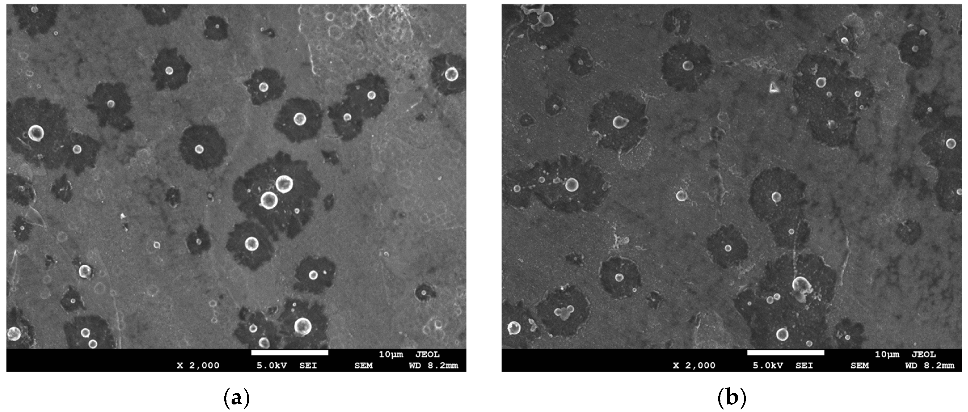
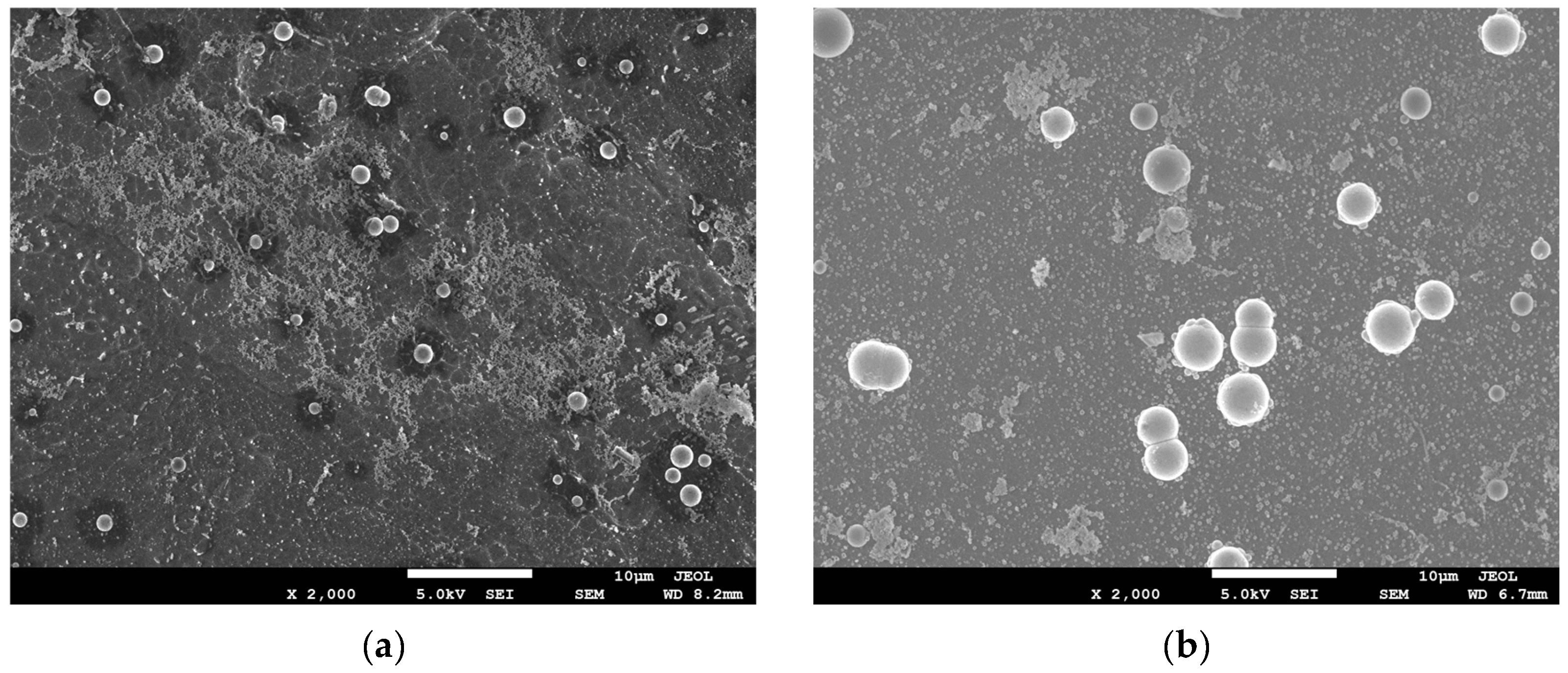
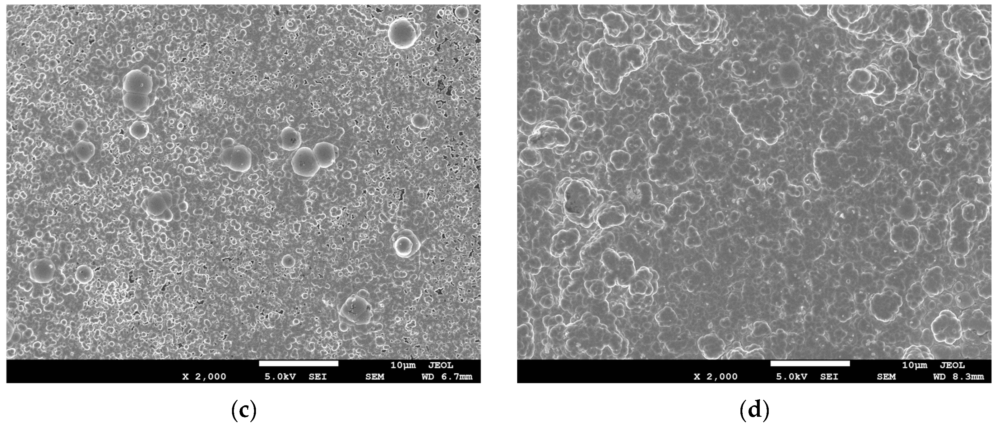
3.1.3. The Evolution of the Upper and Lower Surface Morphology of the Mg–Li Alloy with Reaction Time

The evolution of the upper and lower surface morphology of the Mg–Li alloy with reaction time was observed by SEM, respectively. Combined with Figure 4a,b, it can be inferred that at the initial stage of the reaction, the region where the insoluble phase MgF2 was concentrated did not undergo reaction. While Mg(OH)2 and MgO as easily soluble phases dissolve first, and the reaction equation is shown in Equations (1) and (2) in Section 3.2. Subsequently, the deposition reaction was occurred in this region to produce Ni–P particles, as evidenced by the results in Section 3.1.2. At this stage, there was no significant difference between the upper and lower surfaces.
It can be seen from Figure 4c,d that the few Ni–P particles deposited first on the upper surface were larger in size at a deposition reaction time of 10 min, while the small white Ni–P particles on the lower surface covered a wider area, so the color of the lower surface morphology was relatively light. It can be seen from Figure 4e,f that the lower surface had basically completed the coverage of the coating at a deposition reaction time of 20 min. In contrast, the area on the upper surface where the insoluble phase was more concentrated (the dark area in Figure 4e) still had a large number of pores and incomplete coating coverage, indicating that the horizontal growth rate of the coating on the upper surface was much lower than that on the lower surface. In addition, it was interesting to note that there was a clear “border phenomenon” in the coating at this stage. It was considered that the chemical activity at the grain boundaries of the activated surface film layer was relatively high and the distribution of easily soluble phase was concentrated. Therefore, Ni–P started to be deposited along the grain boundaries relatively earlier, resulting in the appearance of some linear “boundaries” in the surface morphology image [27].
After 45 min of the deposition reaction, as shown in Figure 4g,h, the island-like coating was formed in the region of the easily dissolved soluble phase on the upper surface; this can be further seen from the partial enlargement of Figure 4g. In the region where the insoluble phase was concentrated on the upper surface, the coating exhibits a clear regional hysteresis and the presence of significant pores. Meanwhile, the coating on the lower surface was complete and dense.

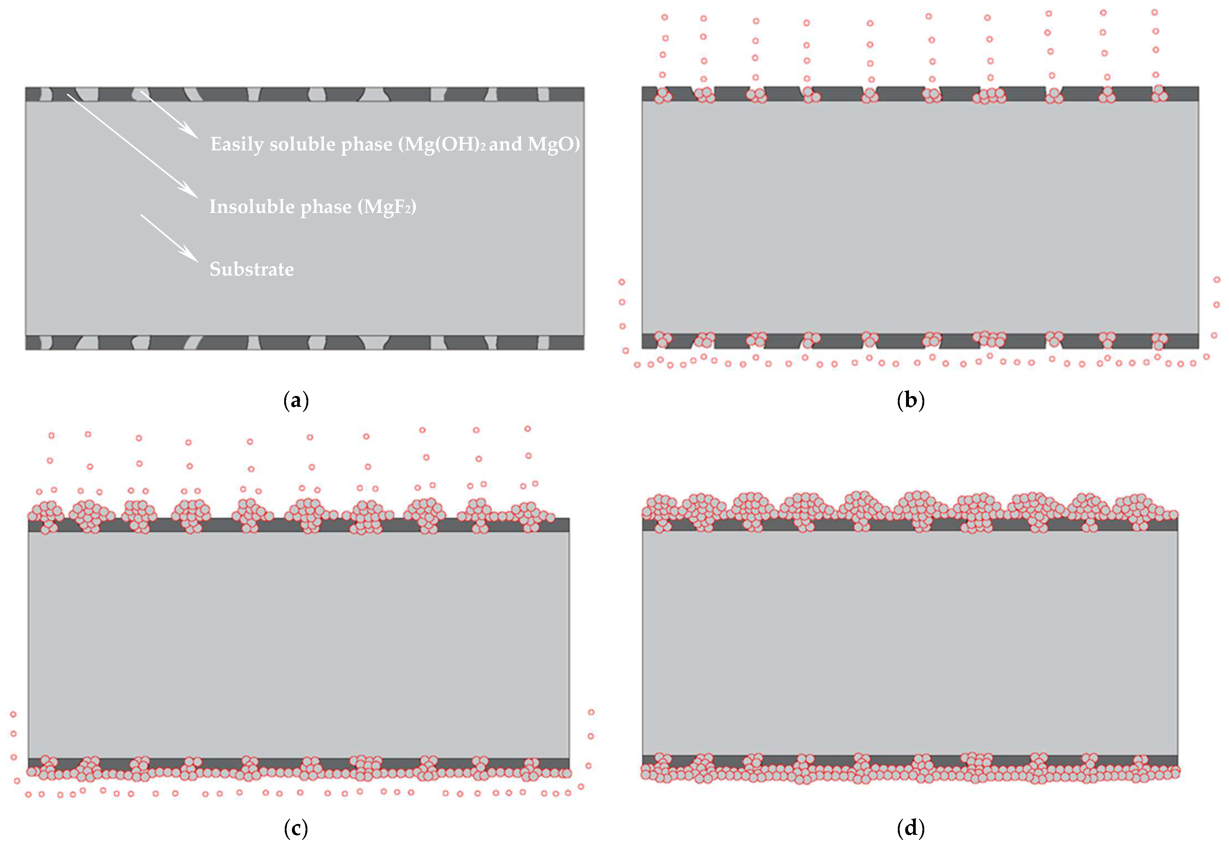
3.2. Deposition Process Inference

Based on the evolution of the upper and lower surface morphology of the Mg–Li alloy with reaction time and experimental phenomena, the reaction flow chart was drawn as shown in Figure 5. After the activation of the sample, the initial state of the surface is shown in Figure 5a, which consists of the easily soluble phase and the insoluble phase. At the initial stage of the reaction, as shown in Figure 5b, the easily soluble phase dissolved first and the reaction equation is as follows [27]:
Mg(OH)2 + 2NH4+ → Mg2+ + 2NH3·H2O
MgO + H2O + 2NH4+ → Mg2+ + 2NH3·H2O
Subsequently, this region took the lead in depositing nickel particles by replacement reaction [28,29]. The reaction equation is as follows:
Mg + Ni2+ → Mg2+ + Ni
2Li + Ni2+ → 2Li2+ + Ni
Immediately afterwards, as shown in Figure 5c, the autocatalytic reaction of depositing Ni–P particles was started with the previously generated Ni particles as the catalytic core [30]. A series of reactions are as follows:
H2PO2 in the reducing agent was catalyzed by the Ni particles generated from the previous replace reaction generates HPO32− and atomic active hydrogen was separated out [31].
H 2 P O 2   +   H 2 O   Ni ( catalyst )   HPO 3 2   +   2 [ H ]   +   H +
The Ni2+ in the plating solution was reduced by atomic active hydrogen to deposit Ni [32].
Ni2+ + 2[H] → Ni + 2H+
The H2PO2 was reacted with atomic active hydrogen to deposit P [33].
H2PO2 + [H] → H2O + OH + P
The remaining atomic active hydrogen interacted to produce H2 [34].
2[H] → H2
During the experiment, the direction of the bubbles on the upper and lower surfaces of the substrate during the autocatalytic reaction stage is observed as shown in Figure 5c. The bubbles generated at the catalytic core on the upper surface flowed directly upward, driving [H] to flow directly upward. The insoluble phase concentrated region lacked [H] from horizontal diffusion, resulting in faster longitudinal growth and slower horizontal unfolding of Ni–P. Meanwhile, the bubbles generated at the catalytic core on the lower surface, under the action of buoyancy, flow uniformly along the horizontal direction, thus promoting the horizontal flow of [H] and the occurrence of the reaction Equations (6)–(8) in the region of insoluble phase concentration, causing the Ni–P particles on the lower surface to diffuse rapidly in the horizontal direction. This would result in the lower surface completing the coating coverage of the substrate faster than the upper surface, which is consistent with the phenomena observed in Figure 4e,f of Section 3.1.3. Finally, the deposition reaction was completed, but significant differences appeared on the upper and lower surfaces as shown in Figure 5d; that is: (1) compared with the lower surface, the longitudinal differences between different areas of the upper surface coating were larger; and (2) the denseness of the upper surface coating was insufficient in areas where the insoluble phase was concentrated.
In summary, it was inferred that the electroless Ni–P plating process of Mg–Li alloy was divided into three main stages as follows. The first stage was the dissolution of the easily soluble phase of the surface film layer. The reaction equation is shown in Equations (1) and (2). The second stage was the replacement reaction stage. The reaction equation is shown in Equations (3) and (4). The third stage was the autocatalytic reaction stage. The reaction equation is shown in Equations (5)–(8).
In view of the above, the reasons for the significant differences formed on the upper and lower surfaces were considered as follows:
  • Due to the special characteristics of Mg–Li alloy material, to be used as a substrate it must be activated with fluoride first. This led to the formation of the surface initial state with Mg(OH)2 and MgO as the easily soluble phase and MgF2 as the insoluble phase on the sample surface. At the first stage, the region where the easily soluble phase was concentrated took the lead in dissolving and forming the catalytic core of Ni and started depositing. Meanwhile, the region where the insoluble phase was concentrated dissolved slowly, leading to a time difference of the deposition reaction in different regions.
  • At the third stage, due to the direct upward flow of the bubbles generated at the catalytic core on the upper surface, which drove [H] to flow directly upward. The region where the insoluble phase was concentrated lacked [H] coming from horizontal diffusion, resulting in a lag in the deposition reaction in this region. While the bubbles generated at the catalytic core on the lower surface, under the effect of buoyancy, the bubbles flowed uniformly along the horizontal direction, thus promoting the horizontal flow of [H], which facilitated the occurrence of the reaction Equations (6)–(8) in the insoluble phase concentration region, which caused the Ni–P particles on the lower surface to spread rapidly in the horizontal direction. This eventually led to the formation of obvious differences between the upper and lower surfaces of the plating.

3.3. The Evolution the Optimized Upper Surface Morphology of the Mg–Li Alloy with Reaction Time

Since there was a significant lag in the horizontal growth rate of the upper surface coating compared to the vertical growth rate during the process of electroless plating. Therefore, an improvement measure was proposed: placing a baffle in parallel 1 mm above the substrate, with the intention of promoting the horizontal flow of air bubbles as a way to accelerate the horizontal diffusion rate of [H]. The optimization measure of preheating the substrate to the same temperature as the coating solution before electroless plating aims at accelerating the dissolution process of the easily soluble phase in each area of the surface and shortening the time difference between the beginning of Ni–P deposition in each area.
Figure 6a–d shows the evolution of the optimized upper surface morphology of the Mg–Li alloy with reaction time. From Figure 6a, it can be seen that at a deposition reaction time of 2 min, most of the easily soluble phases on the upper surface have dissolved and started depositing Ni–P. However, at the same stage before optimization, Ni–P deposition was not evident in most of the area, which indicated that these optimization measures did shorten the time difference of Ni–P deposition initiation.
When the deposition reaction proceeded to 10 min, as shown in Figure 6b, all areas of the surface had entered the Ni–P deposition stage, and there were no obvious lagging areas. At a deposition reaction time of 20 min, as shown in Figure 6c, the surface was basically covered by the Ni–P layer and only a few pores existed. However, there was still a regional hysteresis in the deposition of the surface layer at the same stage before optimization (as can be seen by comparison with Section 3.1.3, Figure 4e, indicating that the optimization measures did accelerate the horizontal growth rate of the upper surface coating. Furthermore, as seen in Figure 6c, the “boundary phenomenon” of the plating layer was no longer obvious at 20 min, which was considered to be caused by two optimization measures that narrowed the differences in Ni–P deposition near the boundary. At 45 min, as shown in Figure 6d, a complete and dense Ni–P layer was formed on the upper surface of the sample.
In summary, the two optimization measures were considered to perform the following functions: (1) preheating would accelerate the dissolution process of each region of the substrate surface in the plating solution, thus shortening the time difference of the deposition reaction in each region; and (2) the baffle would promote the horizontal flow of bubbles at the catalytic core on the upper surface, thus accelerating the horizontal diffusion rate of [H] and promoting the deposition of Ni–P in the area where the insoluble phase was concentrated.

3.4. Corrosion Resistance Test of Coating

3.4.1. Potentiodynamic Polarization Test

Figure 7 shows the potentiodynamic polarization curves of the substrate, the upper and lower surfaces of the Ni–P coating on magnesium–lithium alloy before and after optimization in 3.5 wt% NaCl solution. As shown in Figure 7, the corrosion potentials of the substrates with the coating all showed a positive shift. The corrosion potential of the upper surface coating (−0.758 V) before optimization showed a significant positive shift compared with that of the magnesium–lithium alloy substrate (−1.465 V). However, compared with the upper surface, the corrosion potential of the lower surface coating (−0.452 V) showed a further positive shift and possessed a lower corrosion current density. This indicated that both the upper and lower surfaces of the Ni–P coating provided certain protection to the substrate after 45 min of electroless plating; however, there was still a significant difference in the corrosion resistance between the upper and lower surfaces, thought to be caused by the lack of denseness of the upper surface coating. After optimization, the corrosion potential of the upper surface coating was −0.445 V, and the corrosion current density decreased by two orders of magnitude compared with that of the substrate. At this time, the polarization curves of both the upper and lower surface coatings had obvious passivation zones. This indicated that both the upper and lower surfaces of the optimized coating showed better corrosion resistance.

3.4.2. Electrochemical Impedance Spectroscopy Test

In order to further evaluate the corrosion resistance of the optimized upper surface coating, EIS tests were performed on the substrate and optimized upper surface coating, and the Nyquist curve is shown in Figure 8a. For the substrate, it showed a high-medium frequency capacitive loop and a medium-low frequency inductive loop. For the optimized upper surface coating, only one capacitive loop was shown. It was generally believed that metal surfaces covered with passivation films might generate inductive loops during the passivation film pitting induction period [35]. However, it can be observed in the Nyquist curve plot that the optimized upper surface coating was clearly free of inductive loop; therefore, it can be assumed that no pitting occurred on the optimized upper surface coating [36,37]. In addition, in general, the radius of curvature of the capacitive loop in the Nyquist diagram was proportional to the charge transfer resistance. The larger the charge transfer resistance, the more difficult the diffusion of ionic reactions in solution, which meant that the sample was more resistant to corrosion [38,39]. From Figure 8a, it can be seen that the radius of curvature of the capacitive loop of the optimized upper surface coating was much larger than that of the substrate, which indicated that the optimized upper surface coating had a good corrosion inhibition effect.
The equivalent circuit diagram of the substrate and the optimized upper surface coating is shown in Figure 8b,c. RS was the solution resistance, RL was the inductive resistance, L was the inductance, and CPE was the constant phase element used instead of pure capacitance. RCT was the charge transfer resistance, which responded to the ease of charge crossing the interface between the two phases of the solution and the sample surface during the reaction [40]. The diagram visually reflects the rapidity of the corrosion rate [41]. The EIS data were fitted based on the equivalent circuit model in Figure 8b,c. The fitting results are shown in Table 3. The RCT value of the optimized upper surface coating was 30,967 Ω·cm2, which increased the charge transfer resistance by 135.7 times compared to the substrate (228.2 Ω·cm2). In summary, it indicated that the optimized upper surface coating had good corrosion resistance.

3.5. Coating Adhesion Test

To ensure that the coating adheres tightly, the adhesion between the optimized surface coating and the substrate was measured by an automatic scratch tester. The diamond conical indenter slid on the coating and the loading force gradually increased. When it reached the critical value, the coating would be scratched and the friction curve would change instantaneously. The critical loading force when the coating was scratched was the coating adhesion force [42,43].
It can be seen from Figure 9 that the friction curve changed instantaneously when the loading force was 55.6 N, indicating that the increase in loading force did not reach the critical value until 55.6 N. This indicated good adhesion between the coating and the substrate.

3.6. Analysis of the Surface Composition of Coatings

Tests were performed with XPS in order to determine the specific composition of the electroless coating. The chemical state and possible substances on the sample surface were judged according to the characteristic binding energies of different elements. Figure 10a shows the XPS survey spectra of the coating surface, which can be found to be composed mainly of C, O, Ni and P elements. The C element was ascribed to the ubiquitous carbon on air-exposed metal surfaces [44]. The XPS spectra of Ni 2p3/2 core level regions are shown in Figure 10b, and the fitting results showed that the peaks at 852.2 eV, 852.6 eV and 853.3 eV correspond to Ni–P, NiO and Ni(OH)2 [44,45], respectively. Figure 10c shows the XPS spectra of P 2p core level regions, with peaks at 129.6 eV and 130.5 eV attributed to P elements and Ni–P, respectively [46]. Figure 10d shows the XPS spectra of O 1s core level regions, with diffraction peaks at 530.1 eV and 531.1 eV attributed to NiO and Ni(OH)2 [46].
In summary, the electroless coating was composed of Ni–P, NiO and Ni(OH)2. No Mg, Li, or F elements were detected on the surface, indicating that the coating coverage was complete.

4. Discussion

In addition to the results presented in this paper, the authors have a few more elements they would like to clarify.
Firstly, similar phenomena were found by the authors’ colleagues when electroless Ni–P plating was performed on the surfaces of other similar alloys. Secondly, prior to optimization using ultrasonic techniques, the electroless Ni–P coating prepared by Elsa Georgiza [10] on the surface of magnesium alloys was similar to the upper surface morphology of the coating in this paper. It also seemed to suffer from excessive longitudinal differences and insufficient denseness.
Interestingly, all of these alloys were treated with fluoride prior to electroless plating. Therefore, the authors proposed a speculation; namely, that all alloy materials pretreated with fluoride may show significant differences between the upper and lower surface coatings after electroless Ni–P plating. However, the results of the authors’ colleagues have not yet been published, and Elsa Georgiza did not characterize the upper and lower surfaces separately. Therefore, the authors could not further determine the reliability of the speculation, and require the assistance of other scholars for this speculation to be proved.

5. Conclusions

1.
The reasons for the significant differences formed on the upper and lower surfaces were considered as follows:
  • Due to the special characteristics of Mg–Li alloy material, when used as a substrate it must be activated with fluoride first, leading to the formation of the surface initial state. At the stage of dissolution of the easily soluble phase (the first stage), the region where the easily soluble phase was concentrated took the lead in dissolving and forming the catalytic core of Ni and started depositing Ni–P earlier. Meanwhile, the region where the insoluble phase was concentrated dissolved slowly, leading to a time difference of the deposition reaction in different regions;
  • At the autocatalytic reaction stage (the third stage), due to the direct upward flow of the bubbles generated at the catalytic core on the upper surface, which drove [H] to flow directly upward, the region where the insoluble phase was concentrated lacked [H] coming from horizontal diffusion, resulting in a lag in the deposition reaction in this region. The bubbles generated at the catalytic core on the lower surface, under the effect of buoyancy, flowed uniformly along the horizontal direction, thus promoting the horizontal flow of [H], which facilitated the occurrence of Ni–P deposition reaction in the insoluble phase concentration region, which caused the Ni–P particles on the lower surface to spread rapidly in the horizontal direction. It eventually led to the formation of obvious differences between the upper and lower surfaces of the plating.
2.
In order to promote the dissolution of the easily soluble phase and accelerate the horizontal flow of [H] on the upper surface, two optimization measures were proposed:
  • Preheating the substrate to the same temperature as the coating solution before electroless plating;
  • Placing a baffle in parallel 1 mm above the substrate during electroless plating.
After optimization, compared with the substrate, the plating structure of the upper surface of the sample was more dense and the corrosion potential was positively shifted by 1.02 V. The corrosion current density decreased by two orders of magnitude, and the charge transfer resistance increased by 135.7 times. It indicated that the corrosion resistance of the upper surface was effectively improved after optimization, and the difference between the upper and lower surfaces of the plating was significantly reduced. In addition, the optimized coating has a good adhesion force of 55.6 N.

Author Contributions

Conceptualization, S.-F.P. and S.-Q.L.; methodology, S.-F.P. and K.-F.C.; validation, S.-Q.L., J.Y. and K.-F.C.; formal analysis, L.Z.; investigation, S.-F.P., Z.-G.Y. and S.-Q.L.; data curation, S.-F.P. and S.-Q.L.; writing—original draft preparation, S.-F.P. and S.-Q.L.; writing—review and editing, S.-F.P., S.-Q.L. and L.Z.; visualization, S.-F.P., J.Y. and S.-Q.L.; supervision, L.Z., Z.-G.Y. and K.-F.C.; project administration, J.Y., Z.-G.Y. and K.-F.C.; funding acquisition, L.Z., S.-F.P. and S.-Q.L. contributed equally to this paper. All authors have read and agreed to the published version of the manuscript.

Funding

This research was funded by the Sichuan Provincial Science and Technology Department, China, (grant No. 20zs2112).

Institutional Review Board Statement

Not applicable.

Informed Consent Statement

Not applicable.

Data Availability Statement

Not applicable.

Acknowledgments

Special thanks to Yun-Xi Deng of University of Zurich for her guidance and assistance in the submission process of this paper.

Conflicts of Interest

The authors declare no conflict of interest.

References

  1. Wang, B.; Hou, J.; Luan, J.; Xu, D.; Sun, H.; Sun, J. The Corrosion Behaviors of an As-Rolled Mg-8Li (in wt.%) Alloy in Two Differently Concentrated NaCl Solutions. Coatings 2022, 12, 406. [Google Scholar] [CrossRef]
  2. Mineta, T.; Hasegawa, K.; Sato, H. High strength and plastic deformability of Mg–Li–Al alloy with dual BCC phase produced by a combination of heat treatment and multi-directional forging in channel die. Mater. Sci. Eng. A 2020, 773, 138867. [Google Scholar] [CrossRef]
  3. Shao, B.; Wu, S.; Shan, D.; Guo, B.; Zong, Y. The effect of thermal cycling process between high and low temperatures on the microstructure and properties of Mg-10Li-3Al-3Zn-0.25Si alloy. Mater. Lett. 2019, 254, 167–170. [Google Scholar] [CrossRef]
  4. Wen, S.; Wang, X.; Ren, Z. Microstructure and Corrosion Resistance of an HVAF-Sprayed Al-Based Amorphous Coating on Magnesium Alloys. Coatings 2022, 12, 425. [Google Scholar] [CrossRef]
  5. Zhao, J.; Jiang, B.; Tang, A.; Chai, Y.; Liu, B.; Sheng, H.; Yang, T.; Huang, G.; Zhang, D.; Pan, F. Deformation behavior and texture evolution inan extruded MgLi sheet with non-basal texture during tensile deformation. Mater. Charact. 2020, 159, 110041. [Google Scholar] [CrossRef]
  6. Tang, S.; Xin, T.; Luo, T.; Ji, F.; Li, C.; Feng, T.; Lan, S. Grain boundary decohesion in body-centered cubic Mg-Li-Al alloys. J. Alloys Compd. 2022, 902, 163732. [Google Scholar] [CrossRef]
  7. Luo, H.; Liu, Y.; Song, B.; Yao, G. Surfacial Modification of Magnesium-Lithium Alloy. Adv. Mater. Res. 2014, 905, 113–118. [Google Scholar] [CrossRef]
  8. Yu, B.; Dai, J.; Ruan, Q.; Liu, Z.; Chu, P. Corrosion Behavior and Mechanism of Carbon Ion-Implanted Magnesium Alloy. Coatings 2020, 8, 734. [Google Scholar] [CrossRef]
  9. Wang, G.; Zhang, M.; Wu, R. Molybdate and molybdate/permanganate conversion coatings on Mg-8.5Li alloy. Appl. Surf. Sci. 2012, 258, 2648–2654. [Google Scholar] [CrossRef]
  10. Georgiza, E.; Novakovic, J.; Vassiliou, P. Characterization and corrosion resistance of duplex electroless Ni-P composite coatings on magnesium alloy. Surf. Coat. Technol. 2013, 232, 432–439. [Google Scholar] [CrossRef]
  11. Brito, M.M.; Artisiani, R.A.; Carlos, I.A. The electrodeposition of Ni-Cu and Ni-Cu-P from aspartate-based baths. J. Alloys Compd. 2022, 890, 161761. [Google Scholar] [CrossRef]
  12. Leng, Z.; Li, T.; Wang, X.; Zhang, S.; Zhou, J. Effect of Graphite Content on the Conductivity, Wear Behavior, and Corrosion Resistance of the Organic Layer on Magnesium Alloy MAO Coatings. Coatings 2022, 12, 434. [Google Scholar] [CrossRef]
  13. Chang, L.M.; Wang, P.; Liu, W. Effect of Amino Acids on the Structure and Corrosion Resistance of Mg-Li Alloy Anodic Oxide Film. Adv. Mater. Res. 2011, 146, 785–788. [Google Scholar] [CrossRef]
  14. Zhang, H.; Yao, G.C.; Wang, S.L.; Liu, Y.H.; Luo, H.J. A chrome-free conversion coating for magnesium–lithium alloy by a phosphate–permanganate solution. Surf. Coat. Technol. 2008, 202, 1825–1830. [Google Scholar] [CrossRef]
  15. Zou, Y.; Zhang, Z.W.; Liu, S.Y.; Chen, D.; Wang, G.X.; Wang, Y.Y.; Zhang, M.L.; Chen, Y.H. Ultrasonic-Assisted Electroless Ni-P Plating on Dual Phase Mg-Li Alloy. J. Electrochem. Soc. 2014, 162, C64–C70. [Google Scholar] [CrossRef]
  16. Zhang, J.; Duan, X.; Hou, A.; Li, J.; Wang, K.; Cai, H. In Situ Preparation of Mg-Al-Co Layered Double Hydroxides on Microarc Oxidation Ceramic Coating of LA103Z Magnesium-Lithium Alloy for Enhanced Corrosion Resistance. J. Mater. Eng. Perform. 2021, 30, 8490–8499. [Google Scholar] [CrossRef]
  17. Radwan, A.B.; Ali, K.; Shakoor, R.A.; Mohammed, H.; Alsalama, T.; Kahraman, R.; Yusuf, M.M.; Abdullah, A.M.; Montemor, M.F.; Helal, M. Properties enhancement of Ni-P electrodeposited coatings by the incorporation of nanoscale Y2O3 particles. Appl. Surf. Sci. 2018, 457, 956–967. [Google Scholar] [CrossRef]
  18. Buchtík, M.; Doskočil, L.; Brescher, R.; Doležal, P.; Másilko, J.; Wasserbauer, J. The Effect of Crystallization and Phase Transformation on the Mechanical and Electrochemical Corrosion Properties of Ni-P Coatings. Coatings 2021, 11, 447. [Google Scholar] [CrossRef]
  19. Huang, C.C.; Hsu, H.C.; Tseng, Y.C. Structural morphology and magnetism of electroless-plated NiP films on a surface-modified Si substrate. Thin Solid Films 2011, 520, 1102–1108. [Google Scholar] [CrossRef]
  20. Jian, S.Y.; Chu, Y.R.; Lin, C.S. Permanganate conversion coating on AZ31 magnesium alloys with enhanced corrosion resistance. Corros. Sci. 2015, 93, 301–309. [Google Scholar] [CrossRef]
  21. Chang, J.K.; Lin, C.S.; Wang, W.R. Oxidation and corrosion behavior of commercial 5wt% Al-Zn coated steel during austenitization heat treatment. Surf. Coat. Technol. 2018, 350, 880–889. [Google Scholar] [CrossRef]
  22. Milcius, D.; Grbović-Novaković, J.; Zostautienė, R.; Lelis, M.; Girdzevicius, D.; Urbonavicius, M. Combined XRD and XPS analysis of ex-situ and in-situplasma hydrogenated magnetron sputtered Mg films. J. Alloys Compd. 2015, 647, 790–796. [Google Scholar] [CrossRef]
  23. Zhang, Z.; Jin, Z.; Guo, J.; Han, X.; Mu, Q.; Zhu, X. A novel chemical mechanical polishing slurry for yttrium aluminum garnet crystal. Appl. Surf. Sci. 2019, 496, 43601. [Google Scholar] [CrossRef]
  24. Jin, Z.; Jia, Y.; Zhang, K.S.; Kong, L.T.; Sun, B.; Shen, W.; Meng, F.L.; Liu, J.H. Effective removal of fluoride by porous MgO nanoplates and its adsorption mechanism. J. Alloys Compd. 2016, 675, 292–300. [Google Scholar] [CrossRef]
  25. Newberg, J.T.; Starr, D.E.; Yamamoto, S.; Kaya, S.; Kendelewicz, T.; Mysak, E.R.; Porsgaard, S.; Salmeron, M.B.; Brown, G.E.; Nilsson, A.; et al. Formation of hydroxyl and water layers on MgO films studied with ambient pressure XPS. Surf. Sci. 2011, 605, 89–94. [Google Scholar] [CrossRef]
  26. Khajuria, P.; Mahajan, R.; Kumar, S.; Prakash, R.; Choudhary, R.J.; Phase, D.M. Surface and spectral investigation of Sm3+ doped MgO-ZrO2 phosphor. Optik 2020, 216, 164909. [Google Scholar] [CrossRef]
  27. Fan, X.; Wang, Y.; Zou, B.; Gu, L.; Huang, W.; Cao, X. Preparation and corrosion resistance of MAO/Ni–P composite coat on Mg alloy. Appl. Surf. Sci. 2013, 277, 272–280. [Google Scholar] [CrossRef]
  28. Shang, W.; Zhan, X.; Wen, Y.; Li, Y.; Zhang, Z.; Wu, F.; Wang, C. Deposition mechanism of electroless nickel plating of composite coatings on magnesium alloy. Chem. Eng. Sci. 2019, 207, 1299–1308. [Google Scholar] [CrossRef]
  29. Zhang, R.; Cai, S.; Xu, G.; Zhao, H.; Li, Y.; Wang, X.; Huang, K.; Ren, M.; Wu, X. Crack self-healing of phytic acid conversion coating on AZ31 magnesium alloy by heat treatment and the corrosion resistance. Appl. Surf. Sci. 2014, 313, 896–904. [Google Scholar] [CrossRef]
  30. Chen, K.; Zhang, P.; Sun, P.; Niu, X.; Hu, C. Electroless Ni-P Plating on Mullite Powders and Study of the Mechanical Properties of Its Plasma-Sprayed Coating. Coatings 2022, 12, 18. [Google Scholar] [CrossRef]
  31. Sharma, A.K.; Suresh, M.R.; Bhojraj, H.; Narayanamurthy, H.; Sahu, R.P. Electroless nickel plating on magnesium alloy. Met. Finish. 1998, 96, 10–16. [Google Scholar] [CrossRef]
  32. Hu, R.; Su, Y.; Liu, H. Deposition behaviour of nickel phosphorus coating on magnesium alloy in a weak corrosive electroless nickel plating bath. J. Alloys Compd. 2016, 658, 555–560. [Google Scholar] [CrossRef]
  33. Feng, L.; Zhang, Y.; Wen, C.; Li, S.; Li, J.; Cheng, D.; Bai, J.; Cui, Q.; Zhang, L. Effect of initial deposition behavior on properties of electroless Ni-P coating on ZK60 and ME20 magnesium alloys. Trans. Nonferr. Met. Soc. 2021, 31, 2307–2322. [Google Scholar] [CrossRef]
  34. Shao, Z.; Cai, Z.; Hu, R.; Wei, S. The study of electroless nickel plating directly on magnesium alloy. Surf. Coat. Technol. 2014, 249, 42–47. [Google Scholar] [CrossRef]
  35. Song, Z.; Xie, Z.; Yu, G.; Hu, B.; He, X.; Zhang, X. A novel palladium-free surface activation process for electroless nickel deposition on micro-arc oxidation film of AZ91D Mg alloy. J. Alloys Compd. 2015, 623, 274–281. [Google Scholar] [CrossRef]
  36. Song, Y.; Shan, D.; Han, E. High corrosion resistance of electroless composite plating coatings on AZ91D magnesium alloys. Electrochim. Acta 2008, 53, 2135–2143. [Google Scholar] [CrossRef]
  37. Song, Y.; Shan, D.; Chen, R.; Han, E. Investigation of surface oxide film on magnesium-lithium alloy. J. Alloys Compd. 2009, 484, 585–590. [Google Scholar] [CrossRef]
  38. Liu, Y.; Li, S.; Wang, Y.; Wang, H.; Gao, K.; Han, Z.; Ren, L. Superhydrophobic and superoleophobic surface by electrodeposition on magnesium alloy substrate: Wettability and corrosion inhibition. J. Colloid Interface Sci. 2016, 478, 164–171. [Google Scholar] [CrossRef]
  39. Hu, C.; Xu, M.; Zhang, J.; Hu, B.; Yu, G. High corrosion resistance of electroless Ni/Ni-B coating from fluoride-free baths on AZ31 magnesium alloy. J. Alloys Compd. 2019, 770, 48–57. [Google Scholar] [CrossRef]
  40. Cao, Y.; Guo, C.; Wu, D.; Zou, Y. Synthesis and corrosion resistance of solid solution Ti3(Al1−xSix)C2. J. Alloys Compd. 2021, 867, 159126. [Google Scholar] [CrossRef]
  41. Kamde, M.A.; Mahton, Y.; Ohodnicki, J.; Roy, M.; Saha, P. Effect of cerim-based conversion coating on corrosion behavior of squeeze cast Mg-4 wt%Y alloy in 0.1 M NaCl solution. Surf. Coat. Technol. 2021, 421, 127451. [Google Scholar] [CrossRef]
  42. Zhao, G.H.; He, Y.D. Plasma electroplating Ni coating on pure copper sheet—The effects of H2SO4 concentration on the microstructure and mechanical properties. Surf. Coat. Technol. 2012, 206, 4411–4416. [Google Scholar] [CrossRef]
  43. Aleksandra, F.; Sławomir, Z.; Agnieszka, K.; Alicja, Ł.; Tomasz, M. Electrophoretic Co-deposition of Polyetheretherketone and Graphite Particles: Microstructure, Electrochemical Corrosion Resistance, and Coating Adhesion to a Titanium Alloy. Materials 2012, 13, 15. [Google Scholar]
  44. Gan, R.; Wang, D.M.; Xie, Z.H.; He, L. Improving surface characteristic and corrosion inhibition of coating on Mg alloy by trace stannous (II) chloride. Corros. Sci. 2017, 123, 147–157. [Google Scholar] [CrossRef]
  45. Stankiewicz, A.; Kefallinou, Z.; Mordarski, G.; Jagoda, Z.; Spencer, B. Surface functionalisation by the introduction of self-healing properties into electroless Ni-P coatings. Electrochim. Acta 2019, 297, 427–434. [Google Scholar] [CrossRef]
  46. Zhan, X.Q.; Shang, W.; Wen, Y.Q.; Li, Y.Q.; Ma, M.M. Preparation and corrosion resistance of a three-layer composite coatings on the Mg alloy. J. Alloys Compd. 2019, 774, 522–531. [Google Scholar] [CrossRef]
Figure 1. The status of the sample during electroless plating.
Coatings 12 01157 g001
Figure 2. (a) XPS survey spectra; (b) XPS spectra of Mg 1s core level regions; (c) XPS spectra of the O 1s core level regions; (d) XPS spectra of F 1s core level regions.
Coatings 12 01157 g002aCoatings 12 01157 g002b
Figure 3. (a) The surface morphology images of the Mg–Li alloy at 2 min into the deposition reaction; (b) EDS spectrum of Mg–Li alloy at 2 min into the deposition reaction; (c,d) element mapping of Mg–Li alloy at 2 min into the deposition reaction.
Coatings 12 01157 g003
Figure 4. The evolution of the upper and lower surface morphology of the Mg–Li alloy with reaction time. Upper surface: (a) 2 min, (c) 10 min, (e) 20 min, (g) 45 min and its partial enlargement; Lower surface: (b) 2 min, (d) 10 min, (f) 20 min, (h) 45 min.
Coatings 12 01157 g004aCoatings 12 01157 g004b
Figure 5. Schematic diagram of the process of depositing Ni–P on the surface of Mg–Li alloy: (a) the initial state, (b) dissolution of easily soluble phase and the replacement reaction, (c) the autocatalytic reaction, and (d) deposition completion.
Coatings 12 01157 g005
Figure 6. The evolution of the optimized upper surface morphology of the Mg–Li alloy with reaction time: (a) 2 min, (b) 10 min, (c) 20 min, (d) 45 min.
Coatings 12 01157 g006aCoatings 12 01157 g006b
Figure 7. Potentiodynamic polarization curves of substrate, the upper and lower surfaces of Ni–P coating on magnesium–lithium alloy before and after optimization in 3.5 wt% NaCl solution: (curve a) magnesium–lithium alloy substrate; (curve b) upper surface of Ni–P coating before optimization; (curve c) lower surface of Ni–P Coating before optimization; (curve d) upper surface of Ni–P coating after optimization.
Coatings 12 01157 g007
Figure 8. EIS diagrams of LZ91 Mg–Li alloy substrate and optimized upper surface Ni–P coating in 3.5 wt% NaCl solution: (a) Nyquist plot; (b) equivalent circuit diagram of the substrate; (c) equivalent circuit diagram of optimized upper surface Ni–P coating.
Coatings 12 01157 g008
Figure 9. The adhesion test of the optimized electroless Ni–P coating of Mg–Li alloy.
Coatings 12 01157 g009
Figure 10. (a) XPS survey spectra; (b) XPS spectra of Ni 2p3/2 core level regions; (c) XPS spectra of the P 2p core level regions; (d) XPS spectra of O 1s core level regions.
Coatings 12 01157 g010
Table 1. The comparison about the corrosion resistance of the surface protection technologies.
MaterialsCoatingSurface TreatmentEcorr/Vicorr/(A/cm−2)RCT/Ω·cm2Reference
Mg–LiAnodic oxide filmAnodizing−1.695.07 × 10−5700[13]
Mg–LiMAO ceramic filmMicro-arc oxidation−1.52.39 × 10−53652[16]
Mg–Liphosphate-permanganatechemical conversion−1.57--[14]
Mg–LiNi–PElectroless plating−0.348 × 10−625,000[15]
Table 2. The composition and conditions of the electroless Ni–P plating bath for magnesium–lithium alloys.
Composition and ConditionsConcentration
NiCO3·2Ni(OH)2·4H2O15 g/L
NaH2PO2·H2O20 g/L
C6H8O7·H2O7 g/L
HF14 mL/L
NH4HF210 g/L
CH3CHOHCOOH15 mL/L
Thiourea1 mg/L
NH3·H2Oa little
pH5.5–6.0
Temperature358.15 K
Table 3. Estimated parameters of the equivalent circuit elements for Mg–Li alloy substrate and optimized upper surface Ni–P coating.
SamplesRS/Ω·cm2RCT/Ω·cm2RL/Ω·cm2L/H·cm−2CPE/(Ω−1·Sn·cm−2)n
A168.9228.2142.9643.50.0002060.87202
B109.230967--1.6384 × 10−50.93368
Publisher’s Note: MDPI stays neutral with regard to jurisdictional claims in published maps and institutional affiliations.

