Review

Thin-Film Coating Methods: A Successful Marriage of High-Quality and Cost-Effectiveness—A Brief Exploration

Institute of Microelectronics and Optoelectronics, Warsaw University of Technology, Koszykowa 75, 00-662 Warszawa, Poland
Coatings 2022, 12(8), 1115; https://doi.org/10.3390/coatings12081115
Submission received: 6 July 2022 / Revised: 23 July 2022 / Accepted: 3 August 2022 / Published: 4 August 2022
(This article belongs to the Special Issue Coatings and Interfaces II)

Abstract

:
In this review, several cost-effective thin-film coating methods, which include dip-coating, spin-coating, spray-coating, blade-coating, and roll-coating, are presented. Each method has its own set of advantages and disadvantages depending on the proposed application. Not all of them are appropriate for large-scale production due to their certain limitations. That is why the coating method should be selected based on the type and size of the substrate, including the thickness and surface roughness of the required thin films. The sol–gel method offers several benefits, such as simplicity in fabrication, excellent film uniformity, the capacity to cover surfaces of any size and over vast areas, and a low processing temperature. Nevertheless, these coating methods are somewhat economical and well managed in low-budget laboratories. Moreover, these methods offer thin films with good homogeneity and low-surface roughness. Furthermore, some other thin-film deposition methods, for instance, physical vapor deposition (PVD) and chemical vapor deposition (CVD), are also discussed. Since CVD is not restricted to line-of-sight deposition, a characteristic shared by sputtering, evaporation, and other PVD methods, many manufacturing methods favor it. However, these techniques require sophisticated equipment and cleanroom facilities. We aim to provide the pros and cons of thin-film coating methods and let the readers decide the suitable coating technique for their specific application.

1. Introduction

Coating is the way of incorporating a thin coating of material into a substrate by deposition in either the liquid phase (solution) or the solid phase (powder or nanoparticles) [1]. The use of coating strategies may be tailored to meet production requirements for coated layer thickness, coated surface roughness, rate, and coating product size, which can be defined by coating velocity, coated film width, and patterning capabilities [2]. The coating operation may be carried out at air pressure or low vacuum conditions. It is categorized according to the solubility of the coating components used. In solution coating, a binder and target material are dissolved in a solution that may coat the substrate directly, and the solution then evaporates from the resultant wet film to produce a dry film. As opposed to this, vacuum deposition techniques including chemical vapor deposition (CVD) [3], physical vapor deposition (PVD) [4], atomic layer deposition (ALD) [5], plasma [6], flame hydrolysis deposition (FHD) [7,8], and sputtering [9] are mostly used to produce thin, conductive [10], semi-conductive [11] and dielectric layers of demanded morphology that are utilized to transfer heat or electricity under low- or high-vacuum conditions. The guiding layer must have a higher refractive index than the substrate and cladding to effectively confine light [12,13]. Consequently, thin-film deposition and local bulk material manipulation are the two major methods that may be used to execute the guiding layer. The thin-layer deposition method includes procedures such as radio frequency (RF)-sputtering and magnetron sputtering, CVD, plasma-enhanced CVD, FHD, spray pyrolysis deposition, pulsed laser deposition, spin-coating, spray-coating, and sol–gel coating. The direct inscription of a channel waveguide (WG) in the substrate using an femtosecond (FS)-laser is an alternative to performing local modifications of the bulk material via ion exchange, ion implantation, or UV radiation.
Using the roll-coating process, a surface is coated with a tiny, micro nanoscale layer of liquid that has been recirculated across a sheet or web. The major goals of the thin layer coating are to increase the surface’s effectiveness, service life, and quality. The coating is widely employed at the industrial level due to its useful benefits and applicability. The manufacturing of paper, paperboard, cellulose thin films, plastic coatings, fibrous fabric sheets, metallic foils, etc. are only a few of the processes in which it is primarily utilized. Most of the chemicals employed in the roll-coating procedure are non-Newtonian fluids that behave in either a viscoelastic or pseudoelastic manner [14,15].
Due to its effective material utilization and direct and accurate patterning with a resolution of 20–30 mm, in contrast to spin-coating as well as other traditional processes, ink-jet printing techniques have drawn interest as a potentially cost-effective way for fabricating Perovskite solar cells (PSCs) [16,17,18]. Regrettably, because of its complexity and poor volume output, ink-jet printing cannot be easily adapted to mass production [19]. With no restrictions on substrate size and minimal polymer use, spray-coating techniques offer a promising future for large-scale manufacturing [20]. They are expected to replace spin-coating methods, the industry standard. The capacity to access a wide range of fluids with different rheology makes it possible to produce completely spray-coated PSC devices. Yet, the use of spray coating in the manufacture of PSC is constrained by the following major problem: a thicker and more uneven layer [21]. Therefore, most current research focuses on improving the morphology of an active layer employing high boiling point solvents [22], additives, solvent combinations, post-thermal annealing, and other spray coating techniques [22].
Spin-coating is a rapid and popular method for depositing thin films on substrates, and its main benefit is that it is simple to create extremely uniform films. When a solution of a particular substance is spun at a fast speed, the centripetal force and the liquid’s surface tension work together to cover the substrate uniformly. Spin-coating produces a thin film with a thickness of a few nm(s) to a few microns after the surplus solvent is removed. Small substrates that range in size from a few millimeters square to a meter or more in diameter are coated using the spin-coating process. The convenience and relative ease of setting up the process, together with the thinness and homogeneity, are the main benefits of the spin-coating approach.
The dip-coating technique is a quick, easy, affordable, and high-quality coating method that is utilized in both industrial and lab applications [23]. The dip-coating method is frequently used for optical coatings, including large-area antireflective coatings for sun control glasses and the manufacture of vehicle rear mirrors. In the dip-coating procedure, a substrate is submerged in a solution of coating components before the solution is drained away. The procedure may be described as the solution-based deposition of an aqueous-based liquid phase onto a substrate’s surface. The requisite material is typically dissolved in solutions and directly applied to the substrate surface. There are several complicated chemical and physical variables used in the dip-coating process. The duration of immersion, speed of withdrawal, dip-coating cycles, density and viscosity, surface tension, substrate surface, and coating solution evaporation factors all affect the thickness and shape of the film.
The paper is arranged as follows: Section 2 presents the basic mechanism and the recent advancements in the dip-coating method. It is one of the easiest and most common methods for producing thin films from a wide range of inorganic, hybrid, and nanocomposite materials. In the spin-coating method, a tiny drop of coating material is put into the substrate’s center before the substrate is rotated at a regulated high speed. The size of the substrate is one of the key drawbacks of spin-coating. High-speed spinning is more challenging as the size goes up since film thinning gets more challenging. The working mechanism and recent progress in this technology are presented in Section 3. Roll-coating is a pre-metered coating that applies coating liquid to a substrate using a succession of rollers. The amount of coating material provided to the substrate is practically independent of the characteristics and structures of the fabric because a metered layer of the coating liquid is first generated on the roller surface before it is transferred to the substrate as discussed in Section 4. Section 5 presents the traditional spray-coating method that is still the most often reported due to its low cost and lack of specialized equipment, though. Some equipment is connected to compressors for photocatalytic coating so that the solution exists at the desired speed and pressure. Similar to the dip-coating technique, the solution must be correctly prepared before being loaded into the spray. Blade coating offers the benefits of large-area homogeneity, little material waste, interlayer dissolution prevention, compatibility with roll-to-roll manufacturing, and more efficient use of active material while still allowing for the preparation of well-defined films as discussed in Section 6. Moreover, there are several other noteworthy physical and chemical deposition methods available and being widely used in research and industry, such as physical vapor deposition (PVD) and chemical vapor deposition (CVD), which are also discussed in Section 7. Additionally, the paper ends with a fine discussion and the author’s opinion on coating methods in Section 8. For quick navigation of the paper’s content, the graphical illustration is given in Figure 1.

2. Dip-Coating

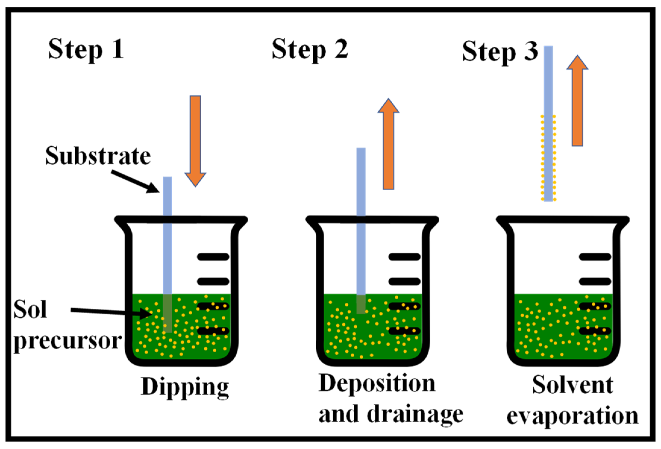
One of the easiest and most common methods for producing thin films from a wide range of inorganic, hybrid, and nanocomposite materials is the sol–gel method [24,25,26]. Considering that it provides for coating a broad range of substrates and complicated geometries, including substrates with holes or intricate patterns, it provides for a high degree of control over the crucial parameters and offers flexibility that cannot be achieved with other traditional processes. There are several ways for wet thin-film coating, namely, dip-coating [27,28], spin-coating [29], spray-coating [30], and flow-coating [31], among others. Fundamentally, the substrate to be coated is submerged in the initial solution and then pulled out at a consistent withdrawal speed during the process, which is carried out under well-measured temperature and air conditions. A fine-tuning of the film properties, including thickness, optical constants, and interior structure, is made feasible by precisely controlling the withdrawal rate and evaporation circumstances. The solution uniformly spreads out along the surface of the substrate because of the collective effects of viscous drag and capillary action. Evaporation takes place at the process’ last stage, resulting in the gelation of the film. The coated substrates often receive a post-heat treatment, which affects the properties of the films [32]. The dip-coating process is shown in Figure 2.
The effectiveness of the dip-coating process can be directly impacted by several factors, such as pH and solution concentration, by changing, for example, its viscosity. However, as contemporary studies employ coating procedures that have already been documented in earlier works, most authors don’t talk much about pH and solution viscosity. Fewer repetitions of the dip-coating process are required to produce a certain thickness or amount of deposited mass when using more viscous solutions since they lead to greater agglomeration and thicker layers of coating [33]. However, the resultant coating could potentially break and clump particles in undesirable places. To obtain past these issues, the dip-coating technique can provide a more homogenous coating by using a less viscous solution in combination with multiple repeats. The structure’s rate of immersion in the solution is yet another factor that might affect the coating’s features [34]. A high rate of immersion, for example, may produce thicker layers because the solution’s viscous forces are increased, causing greater accumulation on the structure’s surface [35].
For thin-film coating techniques to be employed successfully in integrated optics, the film thickness must be completely under control. Because of this, thickness control is important for all thin-film development methods, including sol–gel. It has been reported that the coating speed, angle of inclination, and sol concentration have a major role in determining the ultimate thickness [36,37,38]. In addition, the ultimate heat-treated thickness can also be influenced by the sol viscosity, density, and liquid-vapor surface tension [39]. In [40], it is stated that a cleanroom atmosphere is required for the coating procedure to produce sol–gel thin films with great optical quality. To produce organic dye-doped thin films with tailored porosity for use in chemical sensing and optoelectronics, a three-step sol–gel procedure was developed [41]. Additionally, ceramic films generated from sol–gel are also presented in [24]. Here are some further important papers on the sol–gel technique [42,43,44,45,46,47,48,49,50,51].
Silica, titania, and silica-titania materials produced by the sol–gel technique have all undergone extensive research due to their potential optical uses [52,53,54,55,56,57]. The early part of the 1980s saw the beginning of their use in the production of silica-titania WG films. The first individuals to do so were Herrmann and Wildman. However, they used MERCK’s [53] commercially available liquid-coat solutions rather than synthetic sols. The research team led by Lukosz produced planar evanescent WG chemical/biochemical sensors utilizing these WG films, which were coated on glass substrates using the dip-coating technique and had refractive n = 1.8 at λ = 612.5 μm [54,55,56,58]. These films have optical losses of 2.5 dB/cm for λ = 632.8 μm [58]. Spin-coating was used by Jiwei et al. to fabricate SiO2-TiO2 WG films that were then coated on SiO2/Si (111) substrates [57]. The greatest refractive index of the films was n = 1.87 at λ = 632.8 μm, yet they had very significant optical losses of 7.4 dB/cm. It should be noted that 750 °C annealing temperatures were used to generate such a high refractive index value. The phase change from anatase to rutile is expected to occur at such high temperatures, making WG films much more lossy. There are also other studies [59,60,61,62] reporting the creation and characterization of composite SiO2-TiO2 films, although their waveguiding characteristics were not studied.
If the titania concentration is greater than 20 wt.%, the sol–gel-based manufacturing process of SiO2-TiO2 is quite challenging. This is due to titania’s great propensity to crystallize and produce distinct phases. As a result, manufactured films exhibit large optical losses and are not amorphous [63]. Another issue that causes optical losses to increase over time is long-term stability [64]. These challenges were overcome by Karasinski et al. by creating SiO2-TiO2 WG films with a 50% weight TiO2 content that are low-loss and long-term stable [23]. Using the dip-coating process on BK7 glass substrates, silica-titanium WG layers with a SiO2-TiO2 = 1:1 molar ratio were created, which were subsequently heated to 500 °C. The primary chemical precursors for silica SiO2 and titania TiO2 are tetraethyl orthosilicate Si (OC2H5)4 (TEOS) and tetraethyl orthotitanate Ti (OC2H5)4 (TET), respectively. Water, ethanol, and hydrochloric acid (HCl), which catalyzes the processes of condensation and hydrolysis, are the additional substances used in the procedure.
Moreover, Karasinski and co-workers produced a variety of films on glass substrates at various speeds to identify the key technical characteristic that demonstrates the link between the thickness and refractive index of waveguide films about the speed of substrate removal from the sol. After deposition, the films underwent a 60-min annealing process at 500 °C. Finally, using the monochromatic, multiangle ellipsometer Sentech SE 400 adv with a wavelength of 632.8 nm, the thickness and refractive index of those films were determined. Figure 3 displays the outcomes’ features [36]. From the parameters shown in Figure 3, a single coating procedure can only provide a maximum thickness of roughly 230 nm in the range of withdrawal speed shown. With the repeated coating method, thicker films may be created, which is important because the sample needs to be annealed after each coating. In order to determine the properties shown in Figure 3 of the set of ten SiO2-TiO2 waveguides that were created for this research in a single coating procedure, as well as a few more films in a double coating process.
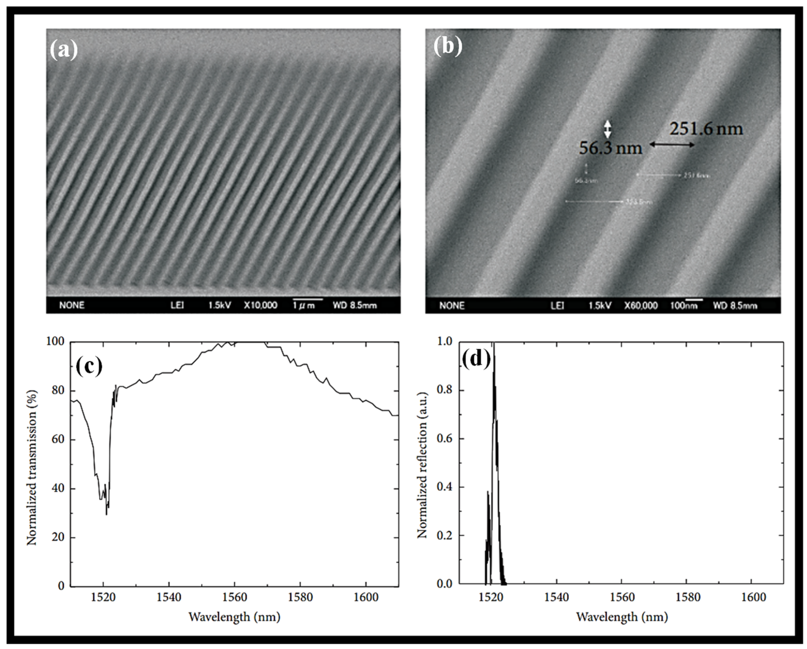
Nanoimprint lithography (NIL) is used to construct a Bragg grating (BG) device in a sol–gel silica WG for bio-photonic applications [65]. A reasonably wide area in the range of several micrometers with a resolution in the order of several nanometers is achieved by the procedure, which also achieves non-standardized lithography in sol–gel silica at a high resolution. In a sol–gel silica optical WG, structures with between 250 and 90 nm resolutions were shown for a sizable area that has not yet been tuned. For a 1 mm long region, a 250 nm periodic structure BG is produced. Two sol–gel silica BG structures, one measuring 250 nm broad and the other 90 nm wide, were then photographed using SEM as shown in Figure 4a,b. The transmission and reflection spectra of the BG structure are presented in Figure 4c,d, respectively. Based on the transmission and reflection spectra of laser light coupled into the WG at a wavelength of 1.55 µm, the efficiency of the grating structure in the WG was evaluated. The transmission and reflection spectra demonstrate that the WG grating was successfully constructed using the NIL procedure.

3. Spin-Coating

Spin-coating is a common method for producing uniform coatings of the necessary thickness; unfortunately, because spin-coating wastes resources at a rate of more than 90%, materials prices increase as the film-coated area grows [66]. Since many years ago, thin films have been deposited via spin-coating. In this method, a tiny drop of coating material is put into the substrate’s center before the substrate is rotated at a regulated high speed. The substrate spins during the spin-coating process around an axis that must be parallel to the region to be coated. Consequently, a thin coating film forms on the surface as the coating material is distributed toward and finally moves away from the substrate’s edge. The kind of coating (viscosity, drying rate, % solids, surface tension, etc.) and the spin processing conditions, such as rotation speed, will determine the final film thickness and other attributes. The stages of the spin-coating process are shown in Figure 5. The size of the substrate is one of the key drawbacks of spin-coating. High-speed spinning is more challenging as the size goes up since film thinning gets more challenging. There is practically limited material efficiency in spin-coating. In general, throughout the process, 95%–98% of the material is thrown off and discarded, and only 2%–5% of the material is dispensed onto the substrate.
To change the solid loading, viscosity, and volatility of the coating solution using this approach, several organic additives are frequently used. This technique is very well adapted to create an ultrathin film on different substrates. In 1958, Emslie and colleagues suggested the spin-coating process model forecast the film thickness as a function of specific physical parameters. The dip-coating parameters can be correlated using this method, though [67]. Huang and Chou further claimed, based on this function, that the solution’s viscosity greatly depends on the shear rate because viscosity is linked to the shear stress. Theoretically, the shear forces caused by viscosity and solution spinning mostly influence the membrane thickness. A thinner, yet more homogeneous membrane would be produced by the spin-coating process’ less viscous precursor solution [68]. Burmann et al. showed that while the solvent evaporation effect is important when employing spin-coating for membrane casting, the rotational duration had little impact on membrane thickness. Nevertheless, the quick solvent evaporation might result in membranes that are unreliable and fragile [69]. Self-supporting ultrathin TiO2 films were disclosed by Hashizume and Kunitake using the spin-coating method [70]. The spin-coating method was used to create the ultrathin layer of polyvinyl alcohol (PVA), which was then coated with titanium tetrabutoxide. The self-supporting ultrathin PVA/titanium composite film was eventually created by dissolving the soluble polymer. Spin-coating is frequently employed in labs to create small-sized membranes, but the technique is not appropriate for producing photocatalytic membranes on a large scale to be used in practical applications.
Due to defects in the thin films that make up organic solar cells, they are typically not repeatable. Wet spun-on PEDOT:PSS films are subjected to an imposed ultrasonic substrate vibration post-treatment to reduce the density of pinholes and defects in PEDOT: PSS, which is the hole transporting layer of a standard polymer solar cell, consisting of glass/ITO/PEDOT:PSS/P3HT:PCBM/Al, and to reduce scattering in device performance (SVPT) [71]. The forced vibration enhances the wet spun-on films’ mixing and homogeneity, which in turn advances the nanostructure of the resulting thin solid films. The average power conversion efficiency (PCE) of 14 identical cells rises by 25% when the SVPT, a mechanical, one-step, and low-cost technique, is used, and the standard deviation drops by 22%, showing that the device’s photovoltaic performance is greatly enhanced and becomes more consistent. This does away with various time-consuming, costly chemical and thermal processes that are typically used to increase cell repeatability [71]. The representation of the whole device and a cross-section of a cell that was photographed using an SEM are shown in Figure 6a and Figure 6b, respectively. The cross-sectional SEM picture in Figure 6b shows that the PEDOT:PSS film has a thickness of roughly 40 nm when the spin rotation is adjusted to 5000 rpm. It is calculated that the PEDOT:PSS film thickness produced at 3000 and 4000 rpm is 52 and 45 nm, respectively. The film was dried at 120 °C for 30 min after the PEDOT:PSS solution was deposited, whether with or without ultrasonic vibrations [71].

4. Roll-Coating

Roll-coating is a pre-metered coating that applies coating liquid to a substrate using a succession of rollers. The amount of coating material provided to the substrate is practically independent of the characteristics and structures of the fabric because a metered layer of the coating liquid is first generated on the roller surface before it is transferred to the substrate. Precise control is achievable and is mainly governed by the rheology of the fluid and the relative speed of two spinning surfaces. A single revolving roller is used in the most basic roll-coating setup. The roller’s upper portion is in touch with the substrate, while its lower half is submerged in a coating liquid bath. A portion of the liquid film formed by the coating liquid on the roller surface is transferred from the roller surface to a substrate as the roller rotates. Hydrodynamics controls the quantity of coating that is applied to the substrate. The elements affecting coating thickness include substrate speed, roller rotation speed, and the rheological characteristics of the coating fluid. One roller serves as both a metering and an application device in this configuration. By adding additional rollers, more accurate control is made possible.
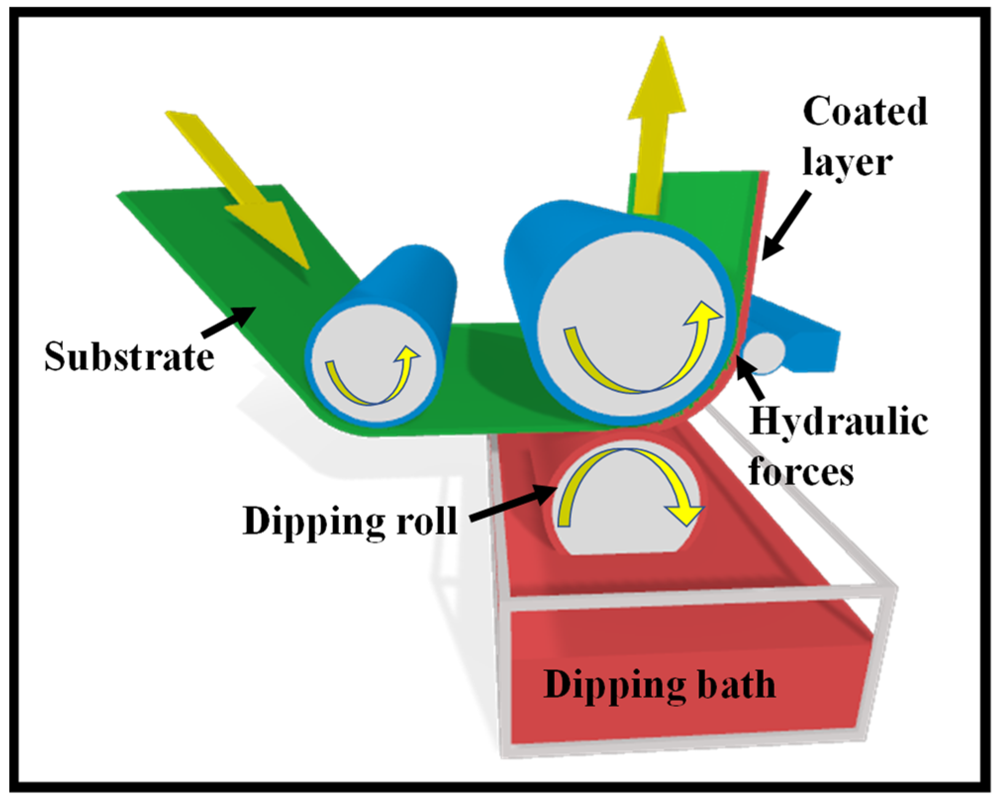
A metering roller, an applicator roller, and a backup roller are all used in a three-roll coating. Nip feed coating and L-head coating are typical three-roll arrangements. In three-roll nip feed coating, the nip created by a metering roller and an applicator roller serves as a reservoir and is inundated with coating liquid. The metering roller rotates in the opposite direction to the applicator roller and measures the amount of coating liquid transferred to the substrate once the applicator roller picks up the coating liquid from the nip. Any coating liquid that remains on the metering roller surface after the coating liquid passes from the metering roller to the applicator roller is cleaned with a doctor blade to prevent coating defects such as streaks or rough film. A backup roller supports the film as it is deposited onto the substrate surface from the applicator roller. Although this design only requires a small amount of coating fluid, it tends to leak. When coating liquid has a low viscosity, it might be difficult. A liquid film is created on the applicator/dipping roller revolving through the coating liquid in a three-roll pan feed or L-head coating, metered by a metering roller, and coated on the substrate fabric on a backup roller as shown in Figure 7.
A fourth roller—a pick-up roller operating at a slower speed—can be installed to boost coating speed. This method is known as a four-roll pan-fed coating system. Since the applicator and metering rollers rotate in opposite directions, the configurations in the figure are referred to as reverse metering. Forward metering is the term used when they both rotate in the same direction. Forward roll metering usually produces unstable, non-uniform films, whereas reverse metering generates smoother, more stable films. As a result, reverse roll coating is increasingly frequently employed. Hot melts, solvent-based coatings, and water-based solutions can all be used for roller coating. Hot melt roller coating involves melting solid pellets between hot melt rollers, creating a melt film, and then depositing the melt film on a substrate. Typically, hot melt is applied after preheating the substrate.
Under the presumption of a small roll curvature, Greener and Middleman performed the theoretical study on roll-coating and examined the scenario where the roll and sheet are moving at the same speed [14]. They were able to determine the precise equation for film thickness and pressure distribution for a Newtonian fluid under the approximation of lubrication. They quantitatively calculated film thickness, pressure, and roll-separating force for viscoelastic and power-law fluids as well. The overall Navier-Stokes equations were solved by the finite element method by Coyle et al. [72]. They then examined the approximated lubrication model’s findings and concluded that it was effective only for systems with large capillary numbers and low surface tension. Hintermaier and White used a lubricating scheme to study the flow of water between two rollers, and their calculated techniques closely matched their reported performance [73]. The coating fluxes for several non-Newtonian fluid models were both theoretically and empirically investigated by Benkreira et al. [74,75,76,77]. Sofou and Missoula used the power lubrication theory, Bingham plastics, and Hershel-Bulkley models to examine the roll-over-web coating flow computationally [78].
Utilizing a third-grade fluid lubrication approximation, Zahid et al. examined the roll coating process and numerically evaluated all the crucial characteristics. By assuming that both the roller and the sheet are porous [79]. They also theoretically explored the second-grade fluid roll coating method [80]. It is expected that the pace at which fluid enters the roller surface will be the same as the rate at which fluid exits the web surface. With the support of the lubrication approximation theory, Ali et al. investigated the web-coating method for a pair stress fluid [81]. They also evaluated the pressure gradient, pressure, velocity, roll-separating force, power input, and other crucial parameters. By bringing the pair stress constant to infinity, the findings were compared to those from the Newtonian fluid. To conduct an experimental investigation of the forward and reverse roll-coating processes in meniscus fluid mechanics, Gaskell et al. adopted an optical sectioning technique [82]. To determine key parameters such as intake flow rate, film thickness, meniscus position, and pressure field, several tests were carried out. Nevertheless, the optimal homotopy asymptotic method (OHAM) was not used to assess the impacts of pair stresses generated during the roll-over-web operation. A semi-analytical approximation method for solving non-linear problems is the OHAM [83]. In contrast to other methods of perturbation, this methodology is independent of any big or small factors and offers a suitable way to manage the convergence of the approximation solution and, if necessary, modify the convergence zones.
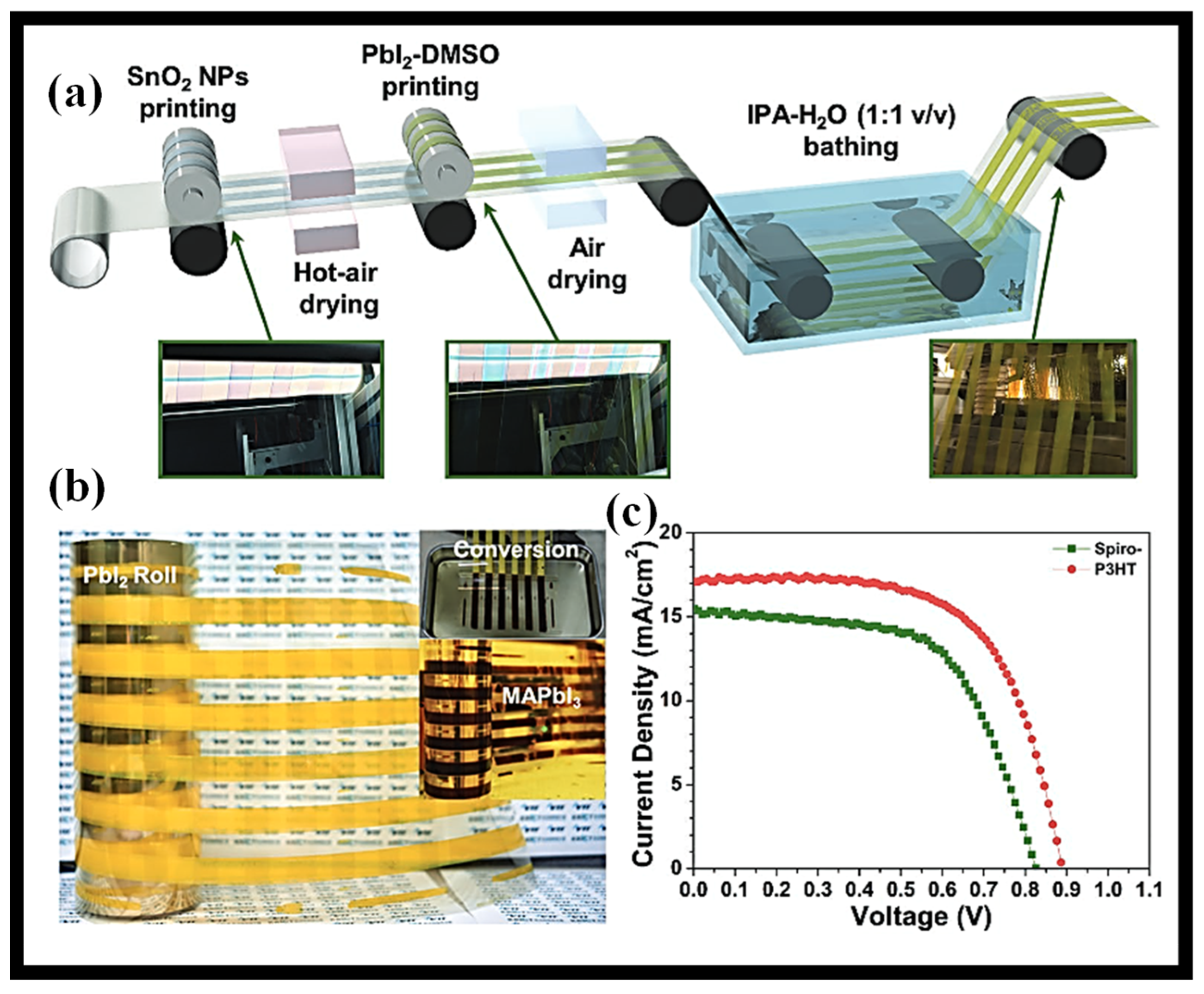
A well-known and efficient method for making solar cells is roll-to-roll (R-2-R). Additionally, several film-forming techniques, including inkjet printing, vacuum deposition, doctor-blading, slot-die coating [84], and CVD, can be used in the production of R-2-R. Flexible substrates are required for the production of R-2-R [85]. Figure 8a depicts the PSCs’ R-2-R process [86]. The substrate must also be able to maintain the technique’s requisite temperature. Due to their limited temperature range (150–200 °C) [87], polyethylene terephthalate (PET) and polyethylene naphthalate (PEN) commonly employ flexible substrates. At low temperatures, Jung et al. produced a device using flexible substrates with a promising PCE of 9.43% [88]. An R-2-R method with 4.9 percent PCE was created by Krebs and colleagues. In the realm of organic photovoltaics, they exploited the benefits of R-2-R in the eye of processing and charges over huge areas. Additionally, they evaluated the creation of R-2-R compatible processes based on one-step and two-step perovskite layer production. Typically, direct coating on substrates is performed through printing techniques. Gravure printing offers an efficient method for printing patterned layers with high throughput and rapid printing speeds. It may also make it possible to produce PSCs on flexible substrates at a low cost and on an industrial scale. Kim et al. proposed a gravure printing-based R-2-R approach, and all of the gravure-printed devices showed an efficiency of 17.2%, whereas the partially R-2-R exhibits 9.7% based on two-step manufacturing of the perovskite layer. Figure 8b,c depicts the PbI2 roll printed and J-V curves of R-2-R [86].

5. Spray-Coating

Considering the abundance of paints and varnishes included in spray devices that can be purchased in stores all over the world, the spray-coating technique may be one of the most useful for covering surfaces [89]. It might be difficult, though, to find a sprayer and a coating solution that work well together. There are also other variants of this procedure, including spray-coating with plasma [90], thermal spray [91], and powder [92], among others. The traditional spray-coating method is still the most often reported due to its low cost and lack of specialized equipment, though. Some equipment is connected to compressors for photocatalytic coating so that the solution exits at the desired speed and pressure [93]. Similar to the dip-coating technique, the solution must be correctly prepared before being loaded into the spray. The precursor solution employed by Montecchio et al. contained merely commercial TiO2 and ethanol at a ratio of 1:20 by mass, respectively, and produced promising benefits after being applied to both steel and ceramic plates on several occasions [94]. Following the structure’s preparation or pretreatment, the coating is carried out using a spray, and the material is then allowed to dry at a specified temperature and time. To obtain the appropriate thickness or catalyst mass, the technique can be performed numerous times. Figure 9 is a schematic illustration of the spray-coating method. In this process, zinc acetate dihydrate and methanol were used in an ultrasonic spray pyrolysis process by Bousmaha et al. to coat ZnO in a glass tube [95]. The methylene blue dye completely degraded during photocatalytic experiments, and the scientists claim that this method is the best for creating thin layers on flat surfaces such as glass.
A fine aerosol is created by forcing printing ink through a nozzle during the spray-painting process. PSC’s typical performance in a spray coating method is constrained by issues including isolated droplets, a non-uniform surface, and pinholes. The distance between the sample and the airbrush, the flow rate, the pressure, the substrate temperature, the concentration of the blend solution, the duration of the spray, the cosolvent mixture, and the number of times the substrate is sprayed are just a few of the process variables for spray coating that have been extensively studied.
With a cell size of 2.5 cm2, the greatest PCE observed is 4.1%. The polymer active layer was prepared using mixed solvents, and the substrate was also heated to 40 °C. It has been shown that decreasing PCE results in a scaling up of the cell area [96]. According to research by Park et al. [97] and Kang et al. [20], the PCE of the devices decreased as the cell area increased. The high sheet resistance of the transparent electrode and the challenging tuning of the large-area deposition process are to blame for this.
In studies on photoelectric devices, the ultrasonic spray coating process (USCP) has proven appealing due to its high material efficiency, cheap manufacturing costs, and suitability to simplify production. Surface tension in the solvent, though, continues to be a major barrier to USCP’s ability to produce a smooth organic layer for OLEDs. By integrating an extra-low surface tension diluent and a surface tension control mechanism, a high-quality polymer anode buffer layer and a tiny molecule emission layer are effectively achieved by USCP [98]. Poly (3,4-ethylene dioxythiophene) polystyrene sulfonate (PEDOT:PSS) films benefit from the addition of low surface tension methyl alcohol because it causes clear phase separation and increases conductivity. Additionally, a surface tension control technique is provided to remove the influence of surface tension during the solvent evaporation stage of ultrasonic spray coating the film.
A two-step sequential deposition method is used to construct methylammonium lead iodide PSCs using simple coating processes such as spray coating and drop-casting [99]. In the first stage, spray coating replaces the often-used lab-scale spin-coating for the deposition of the lead iodide, while the operating variables of the former process are improved to produce a completely coated and homogeneous sheet of lead iodide. In the second phase, the touch-free drop-casting and scalable pulsed-spray coating substitute the dip-coating procedure to deposit methylammonium iodide on top of the lead iodide layer to create a methylammonium lead iodide perovskite. It has been discovered that the efficiency of perovskite films and devices created using pulsed-spray coating and drop-casting is comparable to those created using dip-coating and that these methods, along with drop-casting’s low material requirements, have the potential to take the place of dip-coating in the production of PSCs on a large scale. Spray-drop and spin-drop processes were used to create the winning devices, which showed power conversion efficiencies of 6.92 percent and 9.48 percent, respectively. Higher efficiencies are anticipated because of applying the improved characteristics and additional layers when fabricating devices in a low-humidity environment [99].
The typical constructed devices’ SEM cross-sectional images without the rear contact are shown in Figure 10a,b. The photos demonstrate the formation of a thin, homogeneous layer of spun-on c-TiO2 that is less than 100 nm thick. When compared to perovskite films created with spin-drop coating, spray-drop films are thicker and less homogeneous. Figure 10c displays the characteristics of the current density and voltage. The array of spray-drop devices with a 9 mm2 cell size is seen in the inset image of Figure 10c on a single substrate. Additionally, the average PCE from spin-drop cells (8.45%) is greater than the average for spray-drop cells (5.95%).

6. Blade-Coating

The production of each layer of the PSC using scalable coating techniques and the development of high-performance devices across a vast area are two of the main obstacles to the effective commercialization of perovskite photovoltaics. The perovskite layer used in today’s most effective PSCs is currently made via spin-coating and anti-solvent dripping to produce dense, pinhole-free layers with good optoelectronic quality [100,101,102,103]. Due to the substantial solution waste generated by spin-coating—up to 90% of the dripping solution might be expelled during spinning [104]—it is not a cost-effective process. Additionally, spin-coating does not produce films that are consistent from one corner to another, which emphasizes large-area substrates (>10 cm × 10 cm). In the end, spin-coating is not appropriate for continuous R-2-R high throughput manufacturing operations and big area in-line processes. To scale up perovskite photovoltaics, it is desirable to create alternative scalable deposition techniques [105].
Uniform perovskite films may now be deposited on large-area surfaces using a variety of industrially scalable deposition methods that are appropriate for high throughput manufacturing. These scalable deposition methods may often be separated into the solution- and vapor-based processes. Blade-coating [106,107], slot-die-coating [108], inkjet printing [109], and spray-coating [110] are examples of solution-based techniques that allow you to incorporate additives into the precursor solution to regulate film production and improve morphology.
Blade coating offers the benefit of large-area homogeneity, little material waste, interlayer dissolution prevention, compatibility with roll-to-roll manufacturing, and more efficient use of active material while still allowing for the preparation of well-defined films [111]. The blade coating method’s quick-drying step avoids the traditional solvent annealing procedure from slowing down manufacturing throughput [112]. The schematic of the blade-coating method is presented in Figure 11. By altering the fabrication conditions, such as the solution concentration, the blade gap, and the blade-coating speed in this process, the film thickness may be adjusted. Using blade-coating techniques, PSC based on PBDTTT-C-T:PCBM was demonstrated, which performed well with the chlorine-free solvents toluene and xylene [112]. The superior solubility of PBDTTTC-T in the chlorine-free solvents is the primary factor contributing to the increase in PSC performance. Additionally, the blade-coated film had smoother surfaces than spin-coated film, which somewhat raised the PCE of the blade-coated PSC.
When P3HT:PCBM PSC was manufactured using several coating processes, including spin-coating, blade-coating, and blade-coating on a hotplate, in addition to blade and spin-coating, the same effect was seen [113]. Because the polymer chains are comparatively able to move freely in the absence of centrifugal force, the polymer films produced by blade-coating with toluene, a chlorine-free solvent, were more structured than those produced by spin-coating. Therefore, it can be said that such approaches provide the necessary ordered and interpenetrating morphology in polymer films without the requirement for any post-production treatment, for instance, solvent annealing and heat annealing.
One of the main difficulties in producing highly efficient organic-inorganic PSCs is scaling them up [114]. On large-area substrates, uniform perovskite films of good crystal quality have been sought after using a variety of scalable techniques, but each of these techniques has its own constraints on the possibility of perovskite photovoltaics’ effective commercialization. Here, a completely scalable hybrid approach is illustrated that combines vapor- and solution-based methods to produce homogeneous perovskite films of excellent quality on surfaces with vast surface areas [115]. This two-step procedure avoids the use of hazardous solvents and makes it simple to include passivation techniques and additives. This technology is used to manufacture PSCs that employ blade-coating to deposit SnO2 electron transporting layers and Spiro-OMeTAD hole transporting layers in ambient air without the need for halogenated solvents. On substrates measuring 5 cm by 5 cm, the manufactured PSCs attained an open-circuit voltage of up to 1.16 V and a PCE of 18.7% with good uniformity [115].
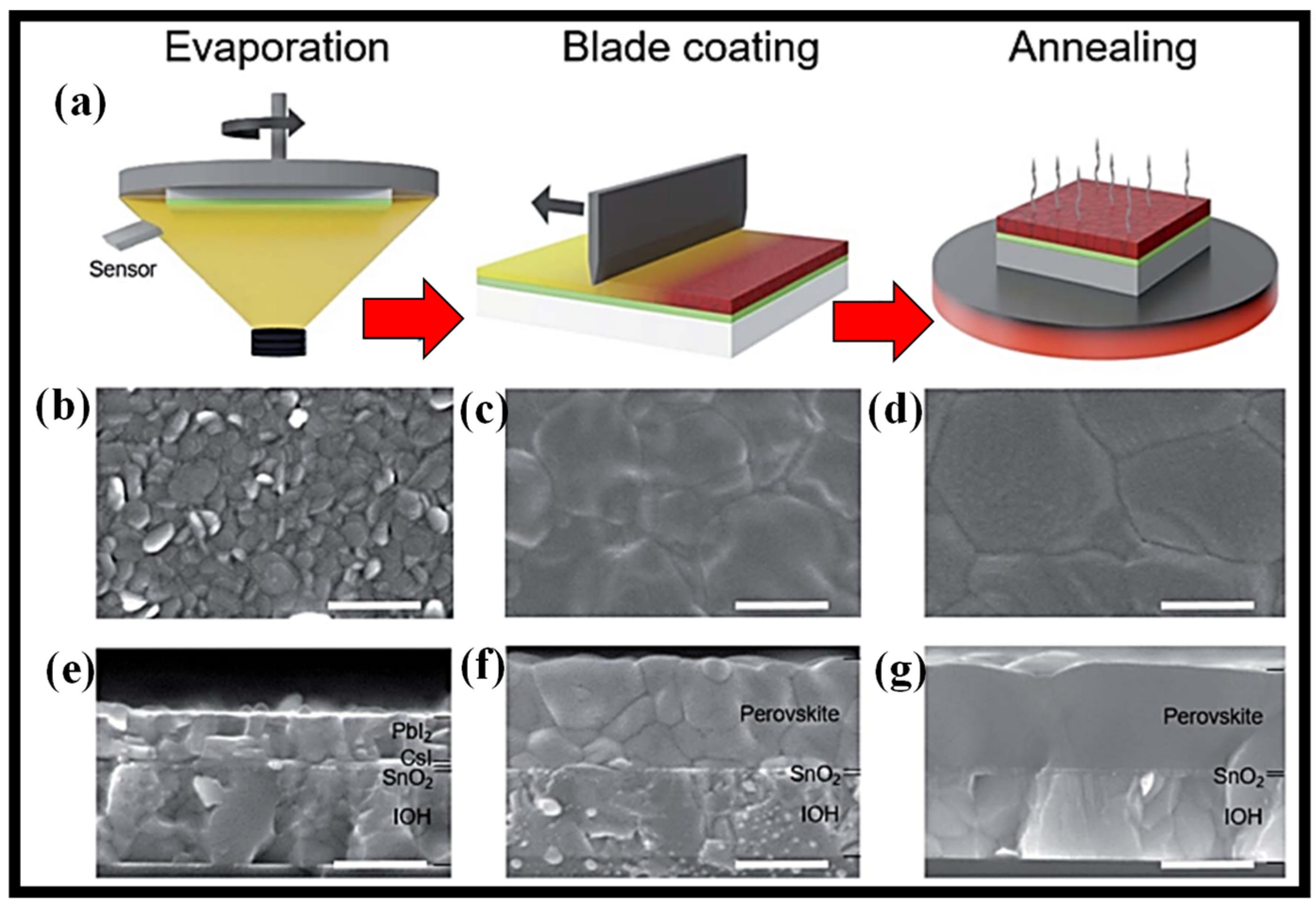
The concept for the scalable PVD/blade-coating technique to create the perovskite layer is shown in Figure 12a [115]. The three phases that make up this hybrid technique. The inorganic halide template is first consecutively formed by thermal evaporation on substrates coated in transparent conducting oxide with an electron transporting layer (SnO2). The layers in this template are 15 nm thick cesium iodide (CsI) on the bottom of a 300 nm thick lead iodide (PbI2) layer. The second stage involves blade-coating the inorganic halide template with the organic halide precursor solution, which is made up of formamidinium iodide (FAI), methylammonium bromide (MABr), and methylammonium chloride (MACl) mixed in isopropanol. To encourage crystal development, lessen grain boundaries, and produce a compact perovskite film with a large grain size, thermal annealing at 150 °C for 15 min in ambient air is performed as the last step. SEM pictures of the film morphology at each stage of the PVD/blade-coating process are shown in Figure 12b–g [115].

7. Other Thin-Film Deposition Methods

Over the past 20 years, a variety of physical and chemical deposition techniques have been employed to produce nanostructured thin films [116,117]. Both strategies provide certain advantages over more conventional methods and have a bright future in the deposition process. New transparent materials must be deposited at low temperatures on conducting and non-conductive substrates to use thin-film technology.
Physical vapor deposition (PVD) techniques include thermal evaporation [118], electron beam [119], pulsed laser [120], molecular beam epitaxy [121], ion plating [122], and activated reactive evaporation [123]. The goal of this deposition technique is to transfer atoms from a source to a substrate such that independent film formation and growth may take place. There are several drawbacks, too; for instance, the requirement for a pricey vacuum environment and expensive instrumentation. The vaporization coating method known as PVD calls for an atomic-level material transfer. This vacuum-based method transfers vaporized material from a source to a substrate, where it condenses after passing through a vacuum or low-pressure gas environment.
The ability to rotate different source materials into the path of the electron, which prevents the vacuum from being disrupted, is one advantage of E-Beam Evaporation. E-beam evaporation is widely used for optical thin-film applications, including laser optics, solar panels, eyeglasses, and architectural glass. A broad variety of materials are deposited using this method. It provides essential mechanical, electrical, and optical qualities. E-beam evaporation offers a high material utilization efficiency compared to other PVD processes, reducing the cost of production.
Chemical vapor deposition (CVD) is a kind of deposition that creates high-performance solid materials, often in a vacuum. The non-volatile solid thin films that are formed on substrates in this method are created by chemical reactions involving organometallic or halide chemicals and other gases. The primary distinction between this approach and PVD is the direction of material deposition on the substrate; PVD is a line-of-site impingement. To deposit materials in a variety of morphologies, including epitaxial, amorphous, monocrystalline, and polycrystalline, CVD is frequently employed in microfabrication techniques. Contrary to PVD, a solid coating is established on the surface of the substrate because of a chemical interaction between a mixture of gases and the bulk surface of the material in CVD. This chemical reaction also allows for the chemical degradation of some of the gas’s components. Additionally, numerous cutting-edge CVD systems and their alternatives, such as PECVD [124] and MOCVD [125], have been commercialized. This permits the assemblies and characteristics of the resultant products to be modified. Typically, CVD does not need high vacuum working settings, making it a popular technology for electronics, optoelectronics, and biomedical applications. Numerous papers describe the deposition of high-quality waveguide films using CVD or its substitutes [126,127,128].
Research is being performed on a technique called spray pyrolysis for producing thin and thick films, ceramic coatings, and powders [129]. It stands out as a highly straightforward and rather cost-effective processing approach, especially when it comes to equipment expenses, compared to many other film deposition procedures. This technique involves spraying a solution onto a heated surface, where it reacts to generate a chemical compound, depositing a thin coating [97]. Chemical reactants are designed so that at the deposition temperature, products other than the necessary components are volatile. It offers an exceedingly straightforward method for creating films of any composition. This technique has been utilized by researchers to create premium thin films that may be used in a variety of optical components [130,131,132,133].
Thin film-based nanomaterials are receiving a lot of interest due to their solid state, low dimensions, and substantial surface area. Hybrid thin/ultrathin (i.e., with a thickness of less than 100 nm) films containing different functional components can be used in cutting-edge research and development, including magnetism, optics, electronics, and catalysis [134,135,136]. The direction of current industry developments is toward printable and flexible photonics and electronics [137]. It has been demonstrated that carbon nanotube (CNT)-based thin films are strong contenders for these uses [135]. Due to its excellent and repeatable film quality and production efficiency, vacuum filtering is one of the numerous production techniques [138,139] that have been widely employed for the fabrication of thin films [140]. Before being used in actual applications, these thin films must frequently be deposited onto the necessary substrates. Thin film transfer has thus far proven to be rather difficult, particularly when applied to diverse substrates and surfaces. Despite being a helpful approach, the Polydimethylsiloxane (PDMS) stamp transfer method has certain limitations, such as the inability to transfer onto arbitrary substrates such as curved or holey surfaces and the inevitable direct contact between the stamp and the film [141]. Another noteworthy transfer technique has had great success in the manufacturing and transfer of carbon-based thin films. It is based on solvent-etchable organic membranes, such as mixed cellulose ester (MCE) filter membranes [142]. The main disadvantage of this approach is that it can only be used with aqueous dispersion systems, such as CNTs or graphene suspended in water (H2O) with the aid of a surfactant.
It is frequently necessary to transfer thin films onto arbitrary substrates or surfaces to construct thin film-based structures or devices. Although greatly sought, controlling and non-destructive transfer methods are still difficult to implement. A generic technique for creating and applying hybrid ultra-thin films. The solution-based in-situ transfer approach demonstrates both its highly regulated and non-destructive characteristics as well as its strong capabilities for thin film transfer onto a variety of surfaces. The completely stretched free-standing thin film is created with a hole structure acting as the support [143]. The manufacture of thin film-coated complicated optical components is made possible by the effective transfer to a curved surface. High transparency (>90% in the visible range), conductivity (1.54 × 10⁴ S/m), and elasticity are displayed in an ultrathin (35 nm) hybrid film that has been put onto PET (50 μm) (radius of curvature down to mm scale). The transfer mechanism that has been revealed would offer a strong path to creating intricate thin film-based structures and systems [143].
In [144], a unique joint manufacturing process was used to create a multilayer barrier thin film based on polyvinylidene difluoride (PVDF) and SiO2 on a PET substrate. The roll-to-roll atmospheric atomic layer deposition system (R2R-AALD) was used to deposit the inorganic SiO2 thin film, and the electrohydrodynamic atomization (EHDA) method was used to create the organic PVDF layer on the surface of the SiO2. The surface shape, chemical composition, and optical characteristics of the multilayer barrier thin films were excellent. The multilayer barrier thin film’s measured values for arithmetic surface roughness and water contact angle were 3.88 nm and 125°, respectively. The multilayer barrier thin film had an overall thickness of 520 nm and a high optical transmittance value of 85%–90%. The barrier thin film’s water vapor transmission rate (WVTR) was 0.9 × 10⁻² g·m−2·day−1. For the creation of multilayer barrier thin films, this dual manufacturing process combination (R2R-AALD and EHDA) has promise for gas barrier applications [144].

8. Author’s Opinion on Coating Methods and Concluding Remarks

Along with the material to be utilized as a framework for photocatalysts, the coating technique must be appropriate and well-planned. Given the seriousness, thermal treatments or methods of acidic solution deposition can destroy the material’s structure. For instance, unlike glass and metals, polymers cannot resist high temperatures. As a result, the approach must be appropriate for specific applications. Dip-coating, spray-coating, electrolytic deposition, and thermal attack are the coating methods that have been utilized most often lately. Other methods, including doctor blades, spin-coatings, and paint-based coatings, have also been documented, albeit less often. It is also possible to find modifications of these methods, always attempting to adapt to the coating structure and material type deposition.
In both industrial settings and research labs, spin-coating, dip-coating, and spray-coating are particularly popular methods for depositing thin films. Due to its great repeatability and adaptability across a broad viscosity range, spin-coating is one of the vital routes for lab scale. It is a rapid and simple method to build homogenous films at a tiny scale, ranging in thickness from a few nanometers to a few micrometers. Due to its high material consumption and confinement to a broad region, it is not suited for industrial scale-up. Since dip-coating can easily and quickly deposit thin films over a broad area, it is frequently used for mirror coating and dye processing. The dip-coating method has the great ability to coat assemblies with geometries that have concealed faces or tight corners, but there is a significant loss of precursor solution during the procedure because the container used must hold enough solution to surround the structure during immersion. The main benefits are the ability to process a big area and the ability to adjust film thickness by withdrawal speed and solution viscosity. Large tanks and a lot of coating solutions are needed for dip-coating. Even though the solution has a lengthy deposition life (a few months), only approximately 20% of it can be utilized.
The spray-coating method allows the flexibility to adjust the system to apply any sort of solution and achieve the appropriate film thickness. It has access to a wide range of fluids. It has significant potential for mass manufacturing and is repeatable. The spray-coating approach can be applied fast if it has the appropriate spray apparatus, but it is not suitable for irregular geometries with concealed faces. Doctor-blading is a method that works well for coatings that are applied on a wide scale. The method may also be used to make thicker films out of a viscous solution. It cannot provide homogeneity at the nanoscale or the very thin sheets that spin-coating can. In blade-coating, coatings are applied to the paper surface and then scraped off to smooth the coating’s surface. The knife coater’s steel scraper makes a difference. The blade coater has the benefit that the coated surface is very flat and unaffected by the base substrate’s surface quality; high solids coating and high-speed coating are both achievable, and the coating does not need to be soft and fluid. The coating is typically not very thick, and it is necessary to maintain the thickness homogeneity of the substrate. The downside is that when foreign matter is mixed into the coating, it is simple to become trapped in the edge of the knife, creating lengthy streaks on the surface of the substrate.

Funding

The research is co-financed by the Foundation for Polish Science from the European Regional Development Fund within the project POIR.04.04.00-00-14D6/18 “Hybrid sensor platforms for integrated photonic systems based on ceramic and polymer materials (HYPHa)” (TEAM-NET program).

Institutional Review Board Statement

Not applicable.

Informed Consent Statement

Not applicable.

Data Availability Statement

Not applicable.

Acknowledgments

The author acknowledge the active contribution of a young researcher Alsu Shakmaeva in the preparation of high-quality images used in this manuscript.

Conflicts of Interest

The author declares no conflict of interest.

Abbreviations

PVDPhysical vapor deposition
CVD Chemical vapor deposition
FHDFlame hydrolysis deposition
ALDAtomic layer deposition
PSCsPerovskite solar cells
PCEPower conversion efficiency
SiO2:TiO2Silica-titania
BGBragg grating
WGWaveguide
NILNano-imprint lithography
SEMScanning electron microscopy
PVAPolyvinyl alcohol
R-2-RRoll-to-Roll
OHAMOptimal homotopy asymptotic method
PDMSPolydimethylsiloxane
PVDFPolyvinylidene difluoride

References

  1. Weinstein, S.; Ruschak, K. Coating flows. Annu. Rev. Fluid Mech. 2004, 36, 29–53. [Google Scholar] [CrossRef]
  2. Krebs, F. Fabrication and processing of polymer solar cells: A review of printing and coating techniques. Sol. Energy Mater. Sol. Cells 2009, 93, 394–412. [Google Scholar] [CrossRef]
  3. Konar, R.; Nessim, G. A mini-review focusing on ambient-pressure chemical vapor deposition (AP-CVD) based synthesis of layered transition metal selenides for energy storage applications. Mater. Adv. 2022, 3, 4471–4488. [Google Scholar] [CrossRef]
  4. Rossnagel, S. Thin film deposition with physical vapor deposition and related technologies. J. Vac. Sci. Technol. A 2003, 21, S74. [Google Scholar] [CrossRef]
  5. Johnson, R.; Hultqvist, A.; Bent, S. A brief review of atomic layer deposition: From fundamentals to applications. Materialstoday 2014, 17, 236–246. [Google Scholar] [CrossRef]
  6. Hong, Y.-S.; Lee, S.-R.; Kim, J.-H.; Lee, S.-Y. Application of a DLC-coating for improving hydrostatic piston shoe bearing performance under mixed friction conditions. Int. J. Precis. Eng. Manuf. 2015, 16, 335–341. [Google Scholar] [CrossRef]
  7. Tandon, P.; Boek, H. Experimental and theoretical studies of flame hydrolysis deposition process for making glasses for optical planar devices. J. Non-Cryst. Solids 2003, 317, 275–289. [Google Scholar] [CrossRef]
  8. Ruano, J.M.; Benoit, V.; Aitchison, J.S.; Cooper, J.M. Flame hydrolysis deposition of glass on silicon for the integration of optical and microfluidic devices. Anal. Chem. 2000, 72, 1093–1097. [Google Scholar] [CrossRef]
  9. Yang, Y.; Kim, K.-H.; Ong, J. A review on calcium phosphate coatings produced using a sputtering process: An alternative to plasma spraying. Biomaterials 2005, 26, 327–337. [Google Scholar] [CrossRef]
  10. Orudzhev, F.; Ramazanov, S.; Sobola, D.; Isaev, A.; Wang, C.; Magomedova, A.; Kadiev, M.; Kaviyarasu, K. Atomic layer deposition of mixed-layered aurivillius phase on TiO2 nanotubes: Synthesis, characterization and photoelectrocatalytic properties. Nanomaterials 2020, 10, 2183. [Google Scholar] [CrossRef]
  11. Dallaev, R.; Sobola, D.; Tofel, P.; Skvarenina, L.; Sedlak, P. Aluminum nitride nanofilms by atomic layer deposition using alternative precursors hydrazinium chloride and triisobutylaluminum. Coatings 2020, 10, 954. [Google Scholar] [CrossRef]
  12. Butt, M.A.; Solé, R.; Pujol, M.C.; Ródenas, A.; Lifante, G.; Choudhary, A.; Murugan, G.S.; Shepherd, D.P.; Wilkinson, J.S.; Aguiló, M.; et al. Fabrication of Y-splitters and Mach-Zehnder structures on (Yb, Nb):RbTiOPO4/RbTiOPO4 epitaxial layers by reactive ion etching. J. Lightwave Technol. 2015, 33, 1863–1871. [Google Scholar] [CrossRef]
  13. Butt, M.A.; Kozlova, E.S.; Khonina, S.N. Conditions of a single-mode rib channel waveguide based on dielectric TiO2/SiO2. Comput. Opt. 2017, 41, 494–498. [Google Scholar] [CrossRef]
  14. Middleman, S. Fundamentals of Polymer Processing; McGraw-Hill: New York, NY, USA, 1977. [Google Scholar]
  15. Bird, R.; Dai, G.; Yarusso, B. The rheology and flow of viscoplastic materials. Rev. Chem. Eng. 1983, 1, 1–70. [Google Scholar] [CrossRef]
  16. Jeong, J.; Lee, J.; Kim, H.; Kim, H.-K.; Na, S.-I. Ink-jet printed transparent electrode using nano-size indium tin oxide particles for organic photovoltaics. Sol. Energy Mater. Sol. Cells 2010, 94, 1840–1844. [Google Scholar] [CrossRef]
  17. Eom, S.; Park, H.; Mujawar, S.; Yoon, S.; Kim, S.-S.; Na, S.; Kang, S.-J.; Khim, D.; Kim, D.-Y.; Lee, S.-H. High efficiency polymer solar cells via sequential inkjet-printing of PEDOT:PSS and P3HT:PCBM inks with additives. Org. Electron. 2010, 11, 1516–1522. [Google Scholar] [CrossRef]
  18. Niu, X.; Li, N.; Chen, Q.; Zhou, H. Insights into large-scale fabrication methods in perovskite photovoltaics. Adv. Energy Sustain. Res. 2021, 2, 2000046. [Google Scholar] [CrossRef]
  19. Voigt, M.; Mackenzie, R.; King, S.; Yau, C.; Atienzar, P.; Dane, J.; Keivanidis, P.; Zadrazil, I.; Bradley, D.; Nelson, J. Gravure printing inverted organic solar cells: The influence of ink properties on film quality and device performance. Sol. Energy Mater. Sol. Cells 2012, 105, 77–85. [Google Scholar] [CrossRef]
  20. Kang, J.-W.; Kang, Y.-J.; Jung, S.; Song, M.; Kim, D.-G.; Kim, C.; Kim, S. Fully spray-coated inverted organic solar cells. Sol. Energy Mater. Sol. Cells 2012, 103, 76–79. [Google Scholar] [CrossRef]
  21. Girotto, C.; Rand, B.; Genoe, J.; Heremans, P. Exploring spray coating as a deposition technique for the fabrication of solution-processed solar cells. Sol. Energy Mater. Sol. Cells 2009, 93, 454–458. [Google Scholar] [CrossRef]
  22. Green, R.; Morfa, A. Performance of bulk heterojunction photovoltaic devices prepared by airbrush spray deposition. Appl. Phys. Lett. 2008, 92, 033301. [Google Scholar] [CrossRef]
  23. Karasinski, P.; Tyszkiewicz, C.; Domanowska, A.; Michalewicz, A.; Mazur, J. Low loss, long time stable sol-gel derived silica-titania waveguide films. Mater. Lett. 2015, 143, 5–7. [Google Scholar] [CrossRef]
  24. Brinker, C.J.; Frye, G.C.; Hurd, A.J.; Ashley, C.S. Fundamentals of sol-gel dip coating. Thin Solid Films 1991, 201, 97–108. [Google Scholar] [CrossRef]
  25. Brinker, C.J.; Ashley, C.S.; Cairncross, R.A.; Chen, K.S.; Hurd, A.J.; Reed, S.T.; Samuel, J.; Schunk, P.R.; Schwartz, R.W.; Scotto, C.S. Sol-gel derived ceramic films-fundamentals and applications. In Metallurgical and Ceramic Protective Coatings; Stern, K.H., Ed.; Springer: Dordrecht, The Netherlands, 1996. [Google Scholar]
  26. Jaglarz, J.; Dulian, P.; Karasinski, P.; Winkowski, P. Scattering phenomena in porous sol-gel-derived silica films. Coatings 2020, 10, 509. [Google Scholar] [CrossRef]
  27. Karasinski, P. Sol-gel derived optical waveguide films for planar sensors with phase modulation. Opt. Appl. 2004, 34, 467–475. [Google Scholar]
  28. Karasinski, P.; Tyszkiewicz, C.; Rogozinski, R. Rib waveguides based on the sol-gel derived SiO2:TiO2 films. Photonics Lett. Pol. 2010, 2, 40–42. [Google Scholar]
  29. Matsui, T.; Komatsu, K.; Sugihara, O.; Kaino, T. Simple process for fabricating a monolithic polymer optical waveguide. Opt. Lett. 2005, 30, 970–972. [Google Scholar] [CrossRef]
  30. Killinger, A.; Gantenbein, G.; Illy, S.; Ruess, T.; Weggen, J.; Martinez-Garcia, V. Plasma spraying of a microwave absorber coating for an RF dummy load. Coatings 2021, 11, 801. [Google Scholar] [CrossRef]
  31. Hongo, A.; Miyagi, M.; Kato, Y.; Suzumura, M.; Kubota, S.; Wang, Y.; Shimomura, T. Fabrication of dielectric-coated silver hollow glass waveguides for the infrared by liquid-flow coating method. In Proceedings of the Biomedical Fiber Optics, Photonics West, San Jose, CA, USA, 5 April 1996; Volume 2677. [Google Scholar]
  32. Faustini, M.; Louis, B.; Albouy, P.; Kuemmel, M.; Grosso, D. Preparation of sol−gel films by dip-coating in extreme conditions. J. Phys. Chem. C 2010, 114, 7637–7645. [Google Scholar] [CrossRef]
  33. Hakki, H.; Allahyari, S.; Rahemi, N.; Tasbihi, M. Surface properties, adherence, and photocatalytic activity of sol-gel dip-coated TiO2-ZnO films on glass plates. C. R. Chim. 2019, 22, 393–405. [Google Scholar] [CrossRef]
  34. Morais, D.; Boaventura, R.; Moreira, F.; Vilar, V. Advances in bromate reduction by heterogeneous photocatalysis: The use of a static mixer as photocatalyst support. Appl. Catal. B Environ. 2019, 249, 322–332. [Google Scholar] [CrossRef]
  35. Zarubica, A. Modified nanostructured titania based thin films in photocatalysis: Kinetic and mechanistic approach. React. Kinet. Mech. Catal. 2015, 115, 159–174. [Google Scholar] [CrossRef]
  36. Butt, M.; Tyszkiewicz, C.; Wojtasik, K.; Karasinski, P.; Kazmierczak, A.; Piramidowicz, R. Subwavelength grating waveguide structures proposed on the low-cost silica-titania platform for optical filtering and refractive index sensing applications. Int. J. Mol. Sci. 2022, 23, 6614. [Google Scholar] [CrossRef]
  37. Butt, M.; Kazmierczak, A.; Tyszkiewicz, C.; Karasinski, P.; Piramidowicz, R. Mode sensitivity exploration of silica-titania waveguide for refractive index sensing applications. Sensors 2021, 21, 7452. [Google Scholar] [CrossRef]
  38. Butt, M.; Tyszkiewicz, C.; Karasinski, P.; Zieba, M.; Hlushchenko, D.; Baraniecki, T.; Kazmierczak, A.; Piramidowicz, R.; Guzik, M.; Bachmatiuk, A. Development of a low-cost silica-titania optical platform for integrated photonics applications. Opt. Express 2022, 30, 23678. [Google Scholar] [CrossRef]
  39. Schroeder, H. Oxide layers deposited from organic solutions. In Physics of Thin Films: Advances in Research and Developments; Academic Press: New York, NY, USA; London, UK, 1969; pp. 87–141. [Google Scholar]
  40. Attia, S.M.; Wang, J.; Wu, G.; Shen, J.; Jianhua, M.A. Review on sol-gel derived coatings: Process, techniques and optical applications. J. Mater. Sci. Technol. 2002, 18, 211–217. [Google Scholar]
  41. Logan, M.N.; Prabakar, S.; Brinker, C.J. Sol-gel-derived silica films with tailored microstructures for applications requiring organic dyes. MRS Online Proc. Libr. 1994, 346, 115–120. [Google Scholar] [CrossRef] [Green Version]
  42. Fidalgo, A.; Ilharco, L.M. The defect structure of sol-gel-derived silica/polytetrahydrofuran hybrid films by FTIR. J. Non-Cryst. Solids 2001, 283, 144–154. [Google Scholar] [CrossRef]
  43. Parin, R.; Rigon, M.; Bortolin, S.; Martucci, A.; Col, D.D. Optimization of hybrid sol-gel coating for dropwise condensation of pure steam. Materials 2020, 13, 878. [Google Scholar] [CrossRef] [Green Version]
  44. Acosta, S.; Ayral, A.; Guizard, C.; Lecornec, C.; Passemard, G.; Moussavi, M. Sol-gel derived silica layers for low-k dielectrics applications. MRS Online Proc. Libr. 2000, 612, 5261. [Google Scholar] [CrossRef]
  45. Boudot, M.; Gaud, V.; Louarn, M.; Selmane, M.; Grosso, D. Sol-Gel based hydrophobic antireflective coatings on organic substrates: A detailed investigation of Ammonia Vapor Treatment (AVT). Chem. Mater. 2014, 26, 1822–1833. [Google Scholar] [CrossRef]
  46. Kim, T.; Song, K. Low-temperature preparation of superhydrophilic coatings using tetraethoxysilane and colloidal silica by sol-gel method. Colloids Surf. A Physicochem. Eng. Asp. 2022, 647, 129105. [Google Scholar] [CrossRef]
  47. Hasaneen, M.; Shalaby, M.; Yousif, N.; Diab, A.; Agammy, E. Structural and optical properties of transparent conducting oxide Cd1-xCrxO thin films prepared by the sol-gel dip-coating method. Mater. Sci. Eng. B 2022, 280, 115703. [Google Scholar] [CrossRef]
  48. Niazmand, M.; Maghsoudipour, A.; Alizadeh, M.; Khahpour, Z.; Kariminejad, A. Effect of dip coating parameters on microstructure and thickness of 8YSZ electrolyte coated on NiO-YSZ by sol-gel process for SOFCs applications. Ceram. Int. 2022, 48, 16091–16098. [Google Scholar] [CrossRef]
  49. Esfahani, M.; Eshaghi, A.; Bakhshi, S. Transparent hydrophobic, self-cleaning, anti-icing and anti-dust nano-structured silica based thin film on cover glass solar cell. J. Non-Cryst. Solids 2022, 583, 121479. [Google Scholar] [CrossRef]
  50. Beldjebli, O.; Bensaha, R.; Panneerselvam, P. Effect of both Sn doping and annealing temperature on the properties of dip-coated nanostructured TiO2 thin films. J. Inorg. Organomet. Polym. Mater. 2022, 32, 1624–1636. [Google Scholar] [CrossRef]
  51. Both, J.; Szabo, G.; Katona, G.; Muresan, L. Tannic acid reinforced sol-gel silica coatings for corrosion protecion of zinc substrates. Mater. Chem. Phys. 2022, 282, 125912. [Google Scholar] [CrossRef]
  52. Karasinski, P.; Tyszkiewicz, C.; Piramidowicz, R.; Kazmierczak, A. Development of integrated photonics based on SiO2:TiO2 sol-gel derived waveguide layers:state of the art, perspectives, prospective applications. Integr. Photonics Platf. Fundam. Res. Manuf. Appl. 2020, 11364, 1136414. [Google Scholar]
  53. Hermann, P.; Wildmann, D. Fabrication of planar dielectric waveguides with high optical damage threshold. IEEE J. Quantum Electron. 1983, 19, 1735–1738. [Google Scholar] [CrossRef]
  54. Lukosz, W.; Tiefenthaler, K. Embossing technique for fabricating integrated optical components in hard inorganic waveguiding materials. Opt. Lett. 1983, 8, 537–539. [Google Scholar] [CrossRef] [Green Version]
  55. Tiefenthaler, K.; Lukosz, W. Sensitivity of grating couplers as integrated-optical chemical sensors. J. Opt. Soc. Am. B 1989, 6, 209–220. [Google Scholar] [CrossRef]
  56. Clerc, D.; Lukosz, W. Direct immunosensing with an integrated-optical output grating coupler. Sens. Actuators B 1997, 40, 53–58. [Google Scholar] [CrossRef]
  57. Jiwei, Z.; Xi, Y.; Liangying, Z. Characterization and optical propagtion loss of sol-gel derived TiO2/SiO2 films. J. Phys. D Appl. Phys. 2000, 33, 3013–3017. [Google Scholar] [CrossRef]
  58. Tiefenthaler, K.; Briguet, V.; Buser, E.; Horisberger, M.; Lukosz, W. Preparation of planar optical SiO2-TiO2 and LiNbO3 waveguides with a dip coating method and embossing technique for fabricating grating couplers and channel waveguides. Proc. SPIE 1983, 401, 165–173. [Google Scholar]
  59. Chrysicopoulou, P.; Davazoglou, D.; Trapalis, C.; Kordas, G. Optical properties of SiO2-TiO2 sol-gel thin films. J. Mater. Sci. 2004, 39, 2835–2839. [Google Scholar] [CrossRef]
  60. Wang, X.; Wu, G.; Zhou, B.; Shen, J. Thermal annealing effect on optical properties of binary TiO2-SiO2 sol-gel coatings. Materials 2013, 6, 76–84. [Google Scholar] [CrossRef] [Green Version]
  61. Kermadi, S.; Agoudjil, N.; Sali, S.; Zougar, L.; Boumaour, M.; Broch, L.; Placido, F. Microstructure and optical dispersion characterization of nanocomposite sol–gel TiO2–SiO2 thin films with different compositions. Spectrochim. Acta Part A Mol. Biomol. Spectrosc. 2015, 145, 145–154. [Google Scholar] [CrossRef]
  62. Lukowiak, A.; Dylewicz, R.; Patela, S.; Strek, W.; Maruszewski, K. Optical properties of SiO2-TiO2 thin film waveguides obtained by the sol-gel method and their applications for sensing purposes. Opt. Mater. 2005, 27, 1501–1505. [Google Scholar] [CrossRef]
  63. Almeida, R.; Morais, P.; Vasconcelos, H. Optical loss mechanism in nanocomposite sol-gel planar waveguides. In Proceedings of the SPIE, Sol-Gel Optics IV, San Diego, CA, USA, 30 July–1 August 1997; pp. 296–303. [Google Scholar]
  64. Weisenbacht, L.; Zelinski, B. The attenuation of sol-gel waveguides measured as a function of wavelength and sample age. In Proceedings of the SPIE 2288 Sol-Gel Optics III, San Diego, CA, USA, 13 October 1994; pp. 630–639. [Google Scholar]
  65. Enami, Y. Fabricating 90 nm resolution structures in sol-gel silica optical waveguides for biosensor applications. J. Sens. 2017, 2017, 4198485. [Google Scholar] [CrossRef] [Green Version]
  66. Blankenburg, L.; Schultheis, K.; Schache, H.; Sensfuss, S.; Schrodner, M. Reel-to-reel wet coatings as an efficient up-scaling technique for the production of bulk-heterojunction polymer solar cells. Sol. Energy Mater. Sol. Cells 2009, 93, 476–483. [Google Scholar] [CrossRef]
  67. Emslie, A.; Bonner, F.; Peck, L. Flow of a viscous liquid on a rotating disk. J. Appl. Phys. 1958, 29, 858. [Google Scholar] [CrossRef]
  68. Huang, Y.-Y.; Chou, K.-S. Studies on the spin coating process of silica films. Ceram. Int. 2003, 29, 485–493. [Google Scholar] [CrossRef]
  69. Burmann, P.; Zornoza, B.; Tellez, C.; Coronas, J. Mixed matrix membranes comprising MOFs and porous silicate fillers prepared via span coating for gas separation. Chem. Eng. Sci. 2014, 107, 66–75. [Google Scholar] [CrossRef]
  70. Hashizume, M.; Kunitake, T. Preparation of self-supporting ultrathin films of titania by spin coating. Langmuir 2003, 19, 10172–10178. [Google Scholar] [CrossRef]
  71. Xie, Y.; Zabihi, F.; Eslamian, M. Fabrication of highly reproducible polymer solar cells using ultrasonic substrate vibration posttreatment. J. Photonics Energy 2016, 6, 045502. [Google Scholar] [CrossRef] [Green Version]
  72. Coyle, D.; Macosko, C.; Scriven, L. Film-splitting flows in forward roll coating. J. Fluid Mech. 1986, 171, 183–207. [Google Scholar] [CrossRef]
  73. Hintermaier, J.; White, R. The splitting of a water film between rotating rolls. TAPPI J. 1965, 48, 617–625. [Google Scholar]
  74. Benkreira, H.; Edwards, M.; Wilkinson, W. A semi-empirical model of the forward roll coating flow of Newtonian fluids. Chem. Eng. Sci. 1981, 36, 423–427. [Google Scholar] [CrossRef]
  75. Benkreira, H.; Edwards, M.; Wilkinson, W. Roll coating of purely viscous liquids. Chem. Eng. Sci. 1981, 36, 429–434. [Google Scholar] [CrossRef]
  76. Benkreira, H.; Edwards, M.; Wilkinson, W. Roll coating operations. J. Non-Newton. Fluid Mech. 1984, 14, 377–389. [Google Scholar] [CrossRef]
  77. Benkreira, H.; Patel, R.; Edwards, M.; Wilkinson, W. Classification and analyses of coating flows. J. Non-Newton. Fluid Mech. 1994, 54, 437–447. [Google Scholar] [CrossRef] [Green Version]
  78. Sofou, S.; Mitsoulis, E. Roll-over-web coating of pseudoplastic and viscoplastic sheets using the lubrication approximation. J. Plast. Film Sheet 2005, 21, 307–333. [Google Scholar] [CrossRef]
  79. Zahid, M.; Haroon, T.; Rana, M.; Siddiqui, A. Roll coating analysis of a third grade fluid. J. Plast. Film Sheet. 2017, 33, 72–91. [Google Scholar] [CrossRef]
  80. Zahid, M.; Rana, M.; Siddiqui, A. Roll coating analysis of a second-grade material. J. Plast. Film Sheet 2018, 34, 232–255. [Google Scholar] [CrossRef]
  81. Ali, N.; Atif, H.; Javed, M.; Sadiq, M. A theoretical analysis of roll-over-web coating of couple stress fluid. J. Plast. Film Sheet. 2018, 34, 43–59. [Google Scholar] [CrossRef] [Green Version]
  82. Gaskell, P.; Savage, M.; Summers, J.; Thompson, H. Modelling and analysis of meniscus roll coating. J. Fluid Mech. 1995, 298, 113–137. [Google Scholar] [CrossRef]
  83. Marinca, V.; Herisanu, N. Determination of periodic solutions for the motion of a particle on a rotating parabola by means of the optimal homotopy asymptotic method. J. Sound Vib. 2010, 329, 1450–1459. [Google Scholar] [CrossRef]
  84. Whitaker, J.; Kim, D.; Larson, B.; Zhang, F.; Berry, J.; Hest, M.; Zhu, K. Scalable slot-die coating of high performance perovskite solar cells. Sustain. Energy Fuels 2018, 2, 2442–2449. [Google Scholar] [CrossRef]
  85. Ahn, S.; Guo, L. High-speed roll-to-roll nanoimprint lithography on flexible plastic substrates. Adv. Mater. 2008, 20, 2044–2049. [Google Scholar] [CrossRef] [Green Version]
  86. Kim, Y.; Yang, T.-Y.; Suhonen, R.; Valimaki, M.; Maaninen, T.; Kemppainen, A.; Jeon, N.; Seo, J. Gravure-printed flexible perovskite solar cells: Toward roll-to-roll manufacturing. Adv. Sci. 2019, 6, 1802094. [Google Scholar] [CrossRef] [Green Version]
  87. Zi, W.; Jin, Z.; Liu, S.; Xu, B. Flexible perovskite solar cells based on green, continuous roll-to-roll printing technology. J. Energy Chem. 2018, 27, 971–989. [Google Scholar] [CrossRef] [Green Version]
  88. Jung, J.; Williams, S.; Jen, A.-Y. Low-temperature processed high-performance flexible perovskite solar cells via rationally optimized solvent washing treatments. RSC Adv. 2014, 4, 62971–62977. [Google Scholar] [CrossRef]
  89. Faisal, N.; Sellami, N.; Venturi, F.; Hussain, T.; Mallick, T.; Muhammad-Sukki, F.; Bishop, A.; Upadhyaya, H.; Katiyar, N.; Goel, S. Large-scale manufacturing route to metamaterial coatings using thermal spray techniques and their response to solar radiation. Emergent Mater. 2021, 4, 1619–1633. [Google Scholar] [CrossRef]
  90. Zhai, M.; Liu, Y.; Huang, J.; Hou, W.; Wu, S.; Zhang, B.; Li, H. Fabrication of TiO2-SrCO3 composite coatings by suspension plasma spraying: Microstructure and enhanced visible light photocatalytic performances. J. Spray Technol. 2020, 29, 1172–1182. [Google Scholar] [CrossRef]
  91. Gardon, M.; Guilemany, J. Milestones in functional titanium dioxide thermal spray coatings: A review. J. Spray Technol. 2014, 23, 577–595. [Google Scholar] [CrossRef] [Green Version]
  92. Li, F.; Lan, X.; Wang, L.; Kong, X.; Xu, P.; Tai, Y.; Liu, G.; Shi, J. An efficient photocatalyst coating strategy for intimately coupled photocatalysis and biodegradation (ICPB) powder spraying method. Chem. Eng. J. 2020, 383, 123092. [Google Scholar] [CrossRef]
  93. Santos, S.; Paulista, L.; Silva, T.; Dias, M.; Lopes, J.; Boaventura, R.; Vilar, V. Intensifying heterogeneous TiO2 photocatalysis for bromate reduction using the NETmix photoreactor. Sci. Total Environ. 2019, 664, 805–816. [Google Scholar] [CrossRef]
  94. Montecchio, F.; Chinungi, D.; Lanza, R.; Engvall, K. Surface treatments of metal supports for photocatalysis applications. Appl. Surf. Sci. 2017, 401, 283–296. [Google Scholar] [CrossRef]
  95. Bousmaha, M.; Bezzerrouk, M.; Kharroubi, B.; Akriche, A.; Naceur, R.; Hattabi, I.; Sandjak-Eddine, K. Enhanced photocatalysis by depositing ZnO thin film in the inner wall of glass tube. Optik 2019, 183, 727–731. [Google Scholar] [CrossRef]
  96. Susanna, G.; Salamandra, L.; Brown, T.; Carlo, A.; Brunetti, F.; Reale, A. Airbrush spray-coating of polymer bulk-heterojunction solar cells. Sol. Energy Mater. Sol. Cells 2011, 95, 1775–1778. [Google Scholar] [CrossRef]
  97. Park, S.-Y.; Kang, Y.-J.; Lee, S.; Kim, D.-G.; Kim, J.-K.; Kim, J.; Kang, J.-W. Spray-coated organic solar cells with large-area of 12.25 cm2. Sol. Energy Mater. Sol. Cells 2011, 95, 852–855. [Google Scholar] [CrossRef]
  98. Liu, S.; Zhang, X.; Zhang, L.; Xie, W. Ultrasonic spray coating polymer and small molecular organic film for organic light-emitting devices. Sci. Rep. 2016, 6, 37042. [Google Scholar] [CrossRef] [PubMed] [Green Version]
  99. Habibi, M.; Ahmadian-Yazdi, M.-R.; Eslamian, M. Optimization of spray coating for the fabrication of sequentially deposited planar perovskite solar cells. J. Photonics Energy 2017, 7, 022003. [Google Scholar] [CrossRef] [Green Version]
  100. Xiao, M.; Huang, F.; Huang, W.; Dkhissi, Y.; Zhu, Y.; Etheridge, J.; Gray-Weale, A.; Bach, U.; Cheng, Y.-B.; Spiccia, L. A fast deposition-crystallization procedure for highly efficient lead iodide perovskite thin-film solar cells. Angew. Chem. Int. Ed. Engl. 2014, 53, 9898–9903. [Google Scholar] [CrossRef] [PubMed]
  101. Jeon, N.; Noh, J.; Kim, Y.; Yang, W.; Ryu, S.; Seok, S. Solvent engineering for high-performance inorganic-organic hybrid perovskite solar cells. Nat. Mater. 2014, 13, 897–903. [Google Scholar] [CrossRef]
  102. Jeong, J.; Kim, M.; Seo, J.; Lu, H.; Ahlawat, P.; Mishra, A.; Yang, Y.; Hope, M.A.; Eickemeyer, F.T.; Kim, M.; et al. Pseudo-halide anion engineering for α-FAPbl3 perovskite solar cells. Nature 2021, 592, 381–385. [Google Scholar] [CrossRef]
  103. Qi, J.; Yang, Z.; Xingwang, Z.; Xiaolei, Y.; Yong, C.; Zema, C.; Qiufeng, Y.; Xingxing, L.; Zhigang, Y.; Jingbi, Y. Surface passivation of perovskite film for efficient solar cells. Nat. Photonics 2019, 13, 460–466. [Google Scholar]
  104. Gu, X.; Shaw, L.; Gu, K.; Toney, M.; Bao, Z. The meniscus-guided deposition of semiconducting polymers. Nat. Commun. 2018, 9, 534. [Google Scholar] [CrossRef]
  105. Li, D.; Zhang, D.; Lim, K.-S.; Hu, Y.; Rong, Y.; Mei, A.; Park, N.-G.; Han, H. A review on scaling up perovskite solar cells. Adv. Funct. Mater. 2021, 31, 2008621. [Google Scholar] [CrossRef]
  106. Deng, Y.; Peng, E.; Shao, Y.; Xiao, Z.; Dong, Z.; Huang, J. Scalable fabrication of efficient organolead trihalide perovskite solar cells with doctor-bladed active layers. Energy Environ. Sci. 2015, 8, 1544–1550. [Google Scholar] [CrossRef]
  107. Razza, S.; Giacomo, F.; Matteocci, F.; Cina, L.; Palma, A.L.; Casaluci, S.; Cameron, P.; D’Epifanio, A.; Licoccia, S.; Reale, A.; et al. Perovskite solar cells and large area modules (100 cm2) based on an air flow-assisted PbI2 blade coating deposition process. J. Power Sources 2015, 277, 286–291. [Google Scholar] [CrossRef]
  108. Vak, D.; Hwang, K.; Faulks, A.; Jung, Y.-S.; Clark, N.; Kim, D.-Y.; Wilson, G.; Watkins, S. Solar cells: 3D printer based slot-die coater as a lab-to-fab translation tool for solution-processed solar cells. Adv. Energy Mater. 2015, 5, 1401539. [Google Scholar] [CrossRef]
  109. Wei, Z.; Chen, H.; Yan, K.; Yang, S. Inkjet printing and instant chemical transformation of a CH3NH3PbI3/nanocarbon electrode and interface for planar perovskite solar cells. Angew. Chem. Int. Ed. Engl. 2014, 53, 13239–13243. [Google Scholar] [CrossRef] [PubMed]
  110. Heo, J.; Lee, M.; Jang, M.; Im, S. Highly efficient CH3NH3PbI3-x Clx mixed halide perovskite solar cells prepared by re-dissolution and crystal grain growth via spray coating. J. Mater. Chem. A 2016, 4, 17636–17642. [Google Scholar] [CrossRef]
  111. Schneider, A.; Traut, N.; Hamburger, M. Analysis and optimization of relevant parameters of blade coating and gravure printing processes for the fabrication of highly efficient organic solar cells. Sol. Energy Mater. Sol. Cells 2014, 126, 149–154. [Google Scholar] [CrossRef]
  112. Tsai, P.-T.; Tsai, C.-Y.; Wang, C.M.; Chang, Y.F.; Meng, H.-F.; Chen, Z.K.; Lin, H.W.; Zan, H.-W.; Horng, S.F.; Lai, Y.C.; et al. High-efficiency polymer solar cells by blade coating in chlorine-free solvents. Org. Electron. 2014, 15, 893–903. [Google Scholar] [CrossRef]
  113. Chang, Y.-H.; Tseng, S.-R.; Chen, C.-Y.; Meng, H.-F.; Chen, E.-C.; Horng, S.-F.; Hsu, C.-S. Polymer solar cell by blade coating. Oragnic Electron. 2009, 10, 741–746. [Google Scholar] [CrossRef]
  114. Mujahid, M.; Chen, C.; Hu, W.; Wang, Z.-K.; Duan, Y. Progress of high-throughput and low-cost flexible perovskite solar cells. Sol. RRL 2020, 4, 1900556. [Google Scholar] [CrossRef]
  115. Siegrist, S.; Yang, S.-C.; Gilshtein, E.; Sun, X.; Tiwari, A.; Fu, F. Triple-cation perovskite solar cells fabricated by a hybrid PVD/blade coating process using green solvents. J. Mater. Chem. A 2021, 9, 26680. [Google Scholar] [CrossRef]
  116. Jilani, A.; Abdel-wahab, M.S.; Hammad, A.H. Advance deposition techniques for thin film and coating. In Modern Technologies for Creating the Thin Film Systems and Coatings; IntechOpen: London, UK, 2017; pp. 137–149. [Google Scholar]
  117. Butt, M.A.; Tyszkiewicz, C.; Karasinski, P.; Zieba, M.; Kazmierczak, A.; Zdonczyk, M.; Duda, L.; Guzik, M.; Olszewski, J.; Martynkien, T.; et al. Optical thin films fabrication techniques—Towards a low-cost solution for the integrated photonic platform: A review of the current status. Materials 2022, 15, 4591. [Google Scholar] [CrossRef]
  118. Boolchandani, S.; Srivastava, S.; Vijay, Y.K. Preparation on InSe thin films by thermal evaporation method and their characterization: Structural, optical, and thermoelectrical properties. J. Nanotechnol. 2018, 2018, 9380573. [Google Scholar] [CrossRef] [Green Version]
  119. Ali, N.; Teixeira, J.A.; Addali, A.; Saeed, M.; Al-Zubi, F.; Sedaghat, A.; Bahzad, H. Deposition of stainless steel thin films: An electron beam physical vapour deposition approach. Materials 2019, 12, 571. [Google Scholar] [CrossRef] [PubMed] [Green Version]
  120. Ogugua, S.N.; Ntwaeaborwa, O.M.; Swart, H.C. Latest development on pulsed laser deposited thin films for advanced luminescence applications. Coatings 2020, 10, 1078. [Google Scholar] [CrossRef]
  121. Opel, M.; Geprags, S.; Althammer, M.; Brenninger, T.; Gross, R. Laser molecular beam epitaxy of ZnO thin films and heterostructures. J. Phys. D Appl. Phys. 2014, 47, 034002. [Google Scholar] [CrossRef] [Green Version]
  122. Martin, P.M. Handbook of deposition technologies for films and coatings. In Science, Applications and Technology, 3rd ed.; Elsevier Inc.: Amsterdam, The Netherlands, 2010; pp. 297–313. [Google Scholar]
  123. Randhawa, H.S.; Bunshah, R.F.; Brock, D.G.; Basol, B.M.; Stafsudd, O.M. Preparation of CuxS thin films by activated reactive evaporation technique. Sol. Energy Mater. 1982, 6, 445–453. [Google Scholar] [CrossRef]
  124. Woehrl, N.; Ochedowski, O.; Gottlieb, S.; Shibasaki, K.; Schulz, S. Plasma-enhanced chemical vapor deposition of graphene on copper substrates. AIP Adv. 2014, 4, 047128. [Google Scholar] [CrossRef] [Green Version]
  125. Cohen, A.; Patsha, A.; Mohapatra, P.K.; Kazes, M.; Ranganathan, K.; Houben, L.; Oron, D.; Ismach, A. Growth-etch metal-organic chemical vapor deposition approach of WS2 atomic layers. ACS Nano 2021, 15, 526–538. [Google Scholar] [CrossRef]
  126. Okada, H.; Baba, M.; Furukawa, M.; Yamane, K.; Sekiguchi, H.; Wakahara, A. Formation of SiO2 film by chemical vapor deposition enhanced by atomic species extracted from a surface-wave generated plasma. AIP Conf. Proc. 2017, 1807, 020006. [Google Scholar]
  127. Matsuura, Y.; Harrington, J.A. Hollow glass waveguides with three-layer dielectric coating fabricated by chemical vapor deposition. J. Opt. Soc. Am. A 1997, 14, 1255–1259. [Google Scholar] [CrossRef]
  128. Matsuura, Y.; Harrington, J.A. Infrared hollow glass waveguides fabricated by chemical vapor deposition. Opt. Lett. 1995, 20, 2078–2080. [Google Scholar] [CrossRef]
  129. Saha, J.K.; Bukke, R.N.; Mude, N.N.; Jang, J. Significant improvment of spray pyrolyzed ZnO thin film by precursor optimization for high mobility thin film transistors. Sci. Rep. 2020, 10, 8999. [Google Scholar] [CrossRef] [PubMed]
  130. Patil, G.E.; Kajale, D.D.; Gaikwad, V.B.; Jain, G.H. Spray pyrolysis deposition of nanostructured tin oxide thin films. Int. Sch. Res. Not. 2012, 2012, 275872. [Google Scholar] [CrossRef] [Green Version]
  131. Cho, J.; Hwang, S.; Ko, D.-H.; Chung, S. Transparent ZnO thin-film deposition by spray pyrolysis for high-performance metal-oxide field-effect transistors. Materials 2019, 12, 3423. [Google Scholar] [CrossRef] [PubMed] [Green Version]
  132. Filipovic, L.; Selberherr, S.; Mutinati, G.C.; Brunet, E.; Steinhauer, S.; Kock, A.; Teva, J.; Kraft, J.; Siegert, J.; Schrank, F. Methods of simulating thin film deposition using spray pyrolysis techniques. Microelectron. Eng. 2014, 117, 57–66. [Google Scholar] [CrossRef]
  133. Ramadhani, M.F.; Pasaribu, M.H.; Yuliarto, B. Fabrication of ZnO nanorod using spray-pyrolysis and chemical bath deposition method. AIP Conf. Proc. 2014, 1586, 74. [Google Scholar]
  134. Gong, K.; Du, F.; Xia, Z.; Durstock, M.; Dai, L. Nitrogen-doped carbon nanotube arrays with high electrocatalytic activity for oxygen reduction. Science 2009, 323, 760–764. [Google Scholar] [CrossRef] [Green Version]
  135. Wu, Z.; Chen, Z.; Du, X.; Logan, J.M.; Sippel, J.; Nikolou, M.; Kamaras, K.; Reynolds, J.R.; Tanner, D.B.; Hebard, A.F.; et al. Transparent, conductive carbon nanotube films. Science 2004, 305, 1273–1276. [Google Scholar] [CrossRef]
  136. De, S.; Higgins, T.M.; Lyons, P.E.; Doherty, E.M.; Nirmalraj, P.N.; Blau, W.J.; Boland, J.J.; Coleman, J.N. Silver nanowire networks as flexible, transparent, conducting films: Extremely high DC to optical conductivity ratios. ACS Nano 2009, 3, 1767–1774. [Google Scholar] [CrossRef]
  137. De, S.; Lyons, P.E.; Sorel, S.; Doherty, E.M.; King, P.J.; Blau, W.J.; Nirmalraj, P.N.; Boland, J.J.; Scardaci, V.; Joimel, J.; et al. Transparent, flexible and highly conductive thin films based on polymer-nanotube composites. ACS Nano 2009, 3, 714–720. [Google Scholar] [CrossRef]
  138. Abe, Y.; Tomuro, R.; Sano, M. Highly efficient direct current electrodeposition of single-walled carbon nanotubes in anhydrous solvents. Adv. Mater. 2005, 17, 2192–2194. [Google Scholar] [CrossRef]
  139. Li, X.; Cai, W.; An, J.; Kim, S.; Nah, J.; Yang, D.; Piner, R.; Velamakanni, A.; Jung, I.; Tutuc, E.; et al. Large-area synthesis of high-quality and uniform graphene films on copper foils. Science 2009, 324, 1312–1314. [Google Scholar] [CrossRef] [PubMed] [Green Version]
  140. Zhang, D.; Ryu, K.; Liu, X.; Polikarpov, E.; Ly, J.; Tompson, M.E.; Zhou, C. Transparent, conductive and flexible nanotube films and their application in organic light-emitting diodes. Nano Lett. 2006, 6, 1880–1886. [Google Scholar] [CrossRef] [PubMed]
  141. Song, J.; Kam, F.Y.; Png, R.Q.; Seah, W.L.; Zhuo, J.M.; Lim, G.K.; Ho, P.K.; Chua, L.L. A general method for transferring graphene onto soft surfaces. Nat. Nanotechnol. 2013, 8, 356–362. [Google Scholar] [CrossRef]
  142. Eda, G.; Fanchina, G.; Chhowalla, M. Large-area ultrathin films of reduced graphene oxide as a transparent and flexible electronic material. Nat. Nanotechnol. 2008, 3, 270–274. [Google Scholar] [CrossRef] [PubMed]
  143. Zhang, Y.; Magan, J.; Blau, W. A general strategy for hybrid thin film fabrication and transfer onto arbitrary substrates. Sci. Rep. 2014, 4, 4822. [Google Scholar] [CrossRef] [Green Version]
  144. Jagadeesan, S.; Lim, J.; Choi, K.; Doh, Y. Hybrid multilayer thin-film fabrication by atmospheric deposition process for enhancing the barrier performance. J. Coat. Technol. Res. 2018, 15, 1391–1399. [Google Scholar] [CrossRef]
Figure 1. Graphical illustration of the optical thin-films coating methods discussed in this review.
Coatings 12 01115 g001
Figure 2. Sequential stages of the sol–gel dip-coating method for thin film deposition: Stage 1—the substrate is dipped and immersed in the sol precursor, Stage 2—the substrate is withdrawn at a steady rate, Stage 3—solvent evaporation produces the gelation of the layer.
Coatings 12 01115 g002
Figure 3. The experimentally determined characteristic of waveguide film thickness and refractive index against change in substrate withdrawal speed from the sol [36].
Coatings 12 01115 g003
Figure 4. Sol–gel silica BG, (a) SEM image of the large area of periodic structure [65], (b) zoomed area of the periodic structure [65], (c) transmission spectrum of the BG structure [65], (d) reflection spectrum of the BG structure [65].
Coatings 12 01115 g004
Figure 5. Stages of spin-coating of thin-film on a substrate. Step 1: Solution is deposited on the substrate. Step 2: Rotational spread out of the solution. Step 3: Evaporation of the solvent.
Coatings 12 01115 g005
Figure 6. Films deposited via spin-coating method (a) Graphical illustration of the solar cell [71], (b) SEM cross-sectional image of a cell [71].
Coatings 12 01115 g006
Figure 7. Roll-coating set-up.
Coatings 12 01115 g007
Figure 8. PSC manufacturing process, (a) Schematic representation of the R-2-R PSC manufacturing process. Optical representations of films wrapped on rolls (Inset) [86], (b) Picture of a PbI2 roll produced using the R-2-R method. (Inset) Illustrations of the perovskite conversion of PbI2 and the MAPbI3 roll [86], (c) J-V curves of printed PSCs printed on rolls with various HTLs [86].
Coatings 12 01115 g008
Figure 9. Spray-coating process.
Coatings 12 01115 g009
Figure 10. SEM cross-sectional images of planar PVSCs made by (a) spin-drop, (b) spray-drop coating without a back contact [99]. (c) J-V curves, where the spin-drop and spray-drop coating processes are used to create the perovskite layer. The instrument constructed using the spray-drop approach is seen in the inset [99].
Coatings 12 01115 g010
Figure 11. Blade-coating setup.
Coatings 12 01115 g011
Figure 12. Perovskite layers and structure following each phase of the hybrid PVD/blade-coating technique [115]. (a) A flowchart showing the three stages involved in fabricating a PVD/blade-coating. Following each phase of manufacturing, SEM top and cross-section view images are shown in (b,e) after evaporation, (c,f) after blade-coating, and (d,g) after annealing process [115].
Coatings 12 01115 g012
Publisher’s Note: MDPI stays neutral with regard to jurisdictional claims in published maps and institutional affiliations.