Abstract
The degradation processes of two self-polishing antifouling coatings containing copper-based agents (CuSCN and Cu2O) in 3.5% NaCl solution and the protection effect of the coating systems were studied by electrochemical impedance spectroscopy (EIS), Fourier transform infrared spectroscopy (FTIR) and scanning electron microscope (SEM/EDS) methods. The results demonstrate that after immersion for 1525 d at room temperature, the two coating systems still have very good protection property for the 5083 Al alloy substrate, manifesting by the high value of the low-frequency impedance. Alternate high and low temperature immersion test (45 °C 12 h + 25 °C 12 h) leads to serious damage to the antifouling topcoat, and the failure is mainly manifested by many micro-pores and micro-cracks. Because the CuSCN antifouling agent particle has bigger diameter and slightly higher solubility than that of Cu2O agent, the micro-pores established after the agents dissolved and released during the hydrolysis process of the antifouling coating are relatively larger, which results in more decrease in the impedance and a worse protective property of the coating system for the substrate.
1. Introduction
Applying antifouling coating is the main method to protect the ships from fouling in a marine environment. Tin-free self-polishing coatings and low surface energy coatings are currently used widely in the marine antifouling coatings’ market [1,2]. Cuprous oxide (Cu2O) is the main anti-fouling agent applied in self-polishing antifouling coatings [3,4,5,6]. However, excessive amount of copper ions released and accumulation will also cause big impacts on ocean ecosystems. Some countries and regions have restricted the use of Cu2O or limit its dosage in formulations [2,4,6]. Copper thiocyanate (CuSCN) is currently another principal biocide, which is described as a substitute of Cu2O when another color is desired. In order to increase the antifouling efficiency of the coatings, some booster substances, such as copper pyrithione (CuPT), zinc pyrithione (ZnPT), zineb, triphenylborane and Sea-Nine 211 (dichloro-isothianolone), are incorporated in the formulations together with the principal copper-based biocide [7,8,9,10,11].
For self-polishing coatings, in the service process, the surface layer of the coating contacts with seawater and will dissolve by hydrolysis reaction, allowing the biocides to be released gradually into the water. As the outermost paint layer becomes depleted of biocides, it will be swept off [12,13]. The commonly used tin-free self-polishing coatings adopt acrylic or methacrylic acid hydrolysable resins as matrix [7,12,14,15]. The anti-fouling agents include Cu2O, CuPT, ZnPT or CuSCN et al. [9,11,12,16,17] In the previous works about self-polishing coatings, most of them focused on developing new multi-functional antifouling coatings [7,18,19], and studying the antifouling mechanism by using submerged coupon tests in seawater or dynamic simulation tests in the lab [7,8,11,14,20] or evaluating the antifouling effect [9,13,15,16,17]. Few of them were involved in the protection effect variation of the coatings on the metallic substrates during the process of resin dissolution and biocides releasing in the self-polishing coatings.
Electrochemical impedance spectroscopy (EIS) is a widely accepted non-destructive technique in the field of polymeric coatings for studying the coating failure and the corrosion processes at the metal/coating interface. Through the use of equivalent circuit modelling or simple spectra analysis, the delamination of coating from the substrate can be quantitatively measured, and coating protective property can be effectively evaluated [21]. There are a few scholars that began to apply the EIS method to investigate the proper degradation of anti-fouling coatings. Bressy et al. [15] studied the water sorption character of acrylic-based coatings containing biocidal tertiary amines by EIS measurements and concluded that the water sorption of the coating decreases as the alkyl chain length of the biocidal amines increases. Peres et al. [22] studied the antifouling performance and water sorption behavior of coatings formulated with rosin matrix, in which the EIS test was used to calculate the water coefficient of diffusion and evaluate the water adsorption behavior of coatings. Thomas et al. [23] studied the electrochemical behavior of polyaniline-polyurethane antifouling coating in saltwater by EIS, and analyzed the influence of PANi addition content on the impedance modulus and determined the maximum processable amount of PANi. Chasse et al. [24] applied EIS and SEM/EDS methods to study the influence of copper-containing coating systems on the localized corrosion of 5083 aluminum alloy in simulated ocean water, and concluded that cuprous oxide has very good biofouling resistance, but there is an increased likelihood of localized corrosion. Zhu et al. [25] synthesized a series of fluorinated/silanized polyacrylate amphiphilic polymers and evaluated their antifouling performance and anticorrosion property by the EIS method.
In the practical application process of antifouling coating, it is usually applied as a top coat on an intermediate coat and an anticorrosion primer, constituting an anti-corrosion and anti-fouling coating system. In the service process of the coating system, along with the resin hydrolysis of the self-polishing coating, the antifoulants are released, being an outer layer, the barrier property of the antifouling coating would be decreased, thereby the protective property of the whole anticorrosion and antifouling coating system to the metallic substrate may be affected. EIS technology is excellent in evaluating the protective property of organic coatings. Cu2O and CuSCN are two principal antifouling biocides mostly widely used in marine paints, with different physical and chemical properties. In this work, the hydrolysis degradation behaviors of the self-polishing coatings containing Cu2O and CuSCN, respectively, in 3.5% NaCl solution, were investigated, and the electrochemical behaviors of the coating systems were studied by EIS test. The aim was to comparatively study the influence of the releasing of two antifouling agents on the coating failure and therefore the protective performance of the anticorrosion and antifouling coating systems to the 5083 Al alloy substrate.
2. Experimental
2.1. Materials and Samples Preparation
The substrate was 5083 Al alloy. The panel was cut into 120 mm × 50 mm × 5 mm specimen, then the surface was sand blasted to Sa 2.5, cleaned with ethanol and acetone, and finally dried sufficiently in the air before the coating was applied.
The applied coatings included two kinds of self-polishing antifouling coatings (859 and 889), an epoxy intermediate coating and a high-build epoxy anticorrosion primer. All the coatings were produced by Shanghai Haiyue Paint Co., Ltd., Shanghai, China. Table 1 shows the coating systems (AF1 and AF2) and related information. The resins of the antifouling coatings were mixtures of zinc pyrithione and copper pyrithione. The main pigments include zinc oxide, iron oxide red and talcum powder. In the 859 topcoat, CuSCN was the principal biocide, and small amounts of ZnPT, triphenyl borane and zineb organic agents were used as booster biocides, with a 40 wt.% total bactericide amount. In the 889 topcoat, Cu2O was the principal biocide, and small amounts of CuPT and ZnPT were booster biocides. The copper content was about 40 wt.%.

Table 1.
Coating systems prepared and the film thickness.
The coatings were brushed on the 5083 Al alloy specimens with a paint applicator (RK, Litlington, UK) successively. The overcoating interval between each layer was 24 h. Finally, the coated samples were cured in a dustproof drying room for 15 d at room temperature. The dry film thickness of each coating layer was measured with a MINTEST6006 thickness meter (Time Instruments Co., Shanghai, China). The total thickness of the coating system was 360 ± 10 μm.
2.2. Corrosion Tests and Measurements
The Al alloy/anticorrosion and antifouling coating system samples were immersed in 3.5% NaCl solution at room temperature. EIS tests were performed on the samples periodically using a PARSTAT 2273 electrochemical workstation (Princeton, Oak Ridge, TN, USA). After four and a half years, the coating surface still looked good. Thus, at 1520 d, the samples were changed to be immersed in 3.5% NaCl solution under an alternating hot and cold temperature condition (45 °C 12 h + 25 °C 12 h), which was used to accelerate the potential failures of the coatings and also can simulate the high temperature in daytime and low temperature at night situation in southern China.
During the EIS test, the working electrode was the coated sample, the reference electrode was the saturated calomel electrode (SCE) and the auxiliary electrode was the platinum electrode. The testing solution was the 3.5% NaCl solution at room temperature. The scanning frequency range was 10−2–105 Hz with a 10 mV sinusoidal voltage amplitude. There were at least three parallel samples under each condition. A ZSimpWin software (V 3.50, San Diego, CA, USA) was used to analyze the EIS data.
The morphology of the coating surface and the cross-section of the sample was observed using a field emission scanning electronic microscope (Hitachi S4700, Tokyo, Japan) and the composition was analyzed by an energy disperse spectroscopy (EDS) (QUANTAX 70, BRUKER, Berlin, Germany). The chemical functional groups of the coatings were analyzed with a TENSOR27 infrared spectrometer (BRUKER, Karlsruhe, Germany). The measuring range was 500–4000 cm−1.
An inductively coupled plasma mass spectrometer (ICP-MS, Agilent Technologies 7700 series, Palo Alto, CA, USA) was used to quantitatively detect the copper ions contents in the 3.5% NaCl solution after the samples were immersed for a period of time. The release rate of the copper ions was calculated according to Formula (1) [26]. Where, R was the release rate (μg/(cm2∙d)); ρ was the copper ions cumulative concentration in the solution (μg/L); V was the solution volume (10 mL); t was testing time (h); A was the test area of the coating (10 cm2).
3. Results and Discussion
3.1. EIS Results of Two Anticorrosion and Antifouling Coating Samples in 3.5% NaCl Solution
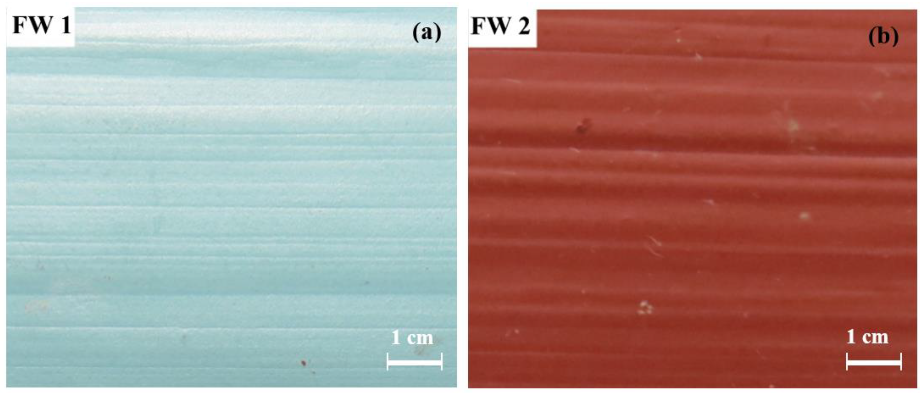
Figure 1 shows the digital photos of the two anticorrosion and antifouling coating samples after immersion in room temperature 3.5% NaCl solution for 600 d. Each of them looks good with bright color. Until 1500 d, the coating surface was intact without blisters and rusts, except for the color turning lighter. These demonstrate that the coating systems have very excellent resistance to degradation in salt water.
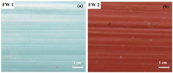
Figure 1.
Digital photos of (a) FW1 and (b) FW2 coating surface after immersion for 600 d.
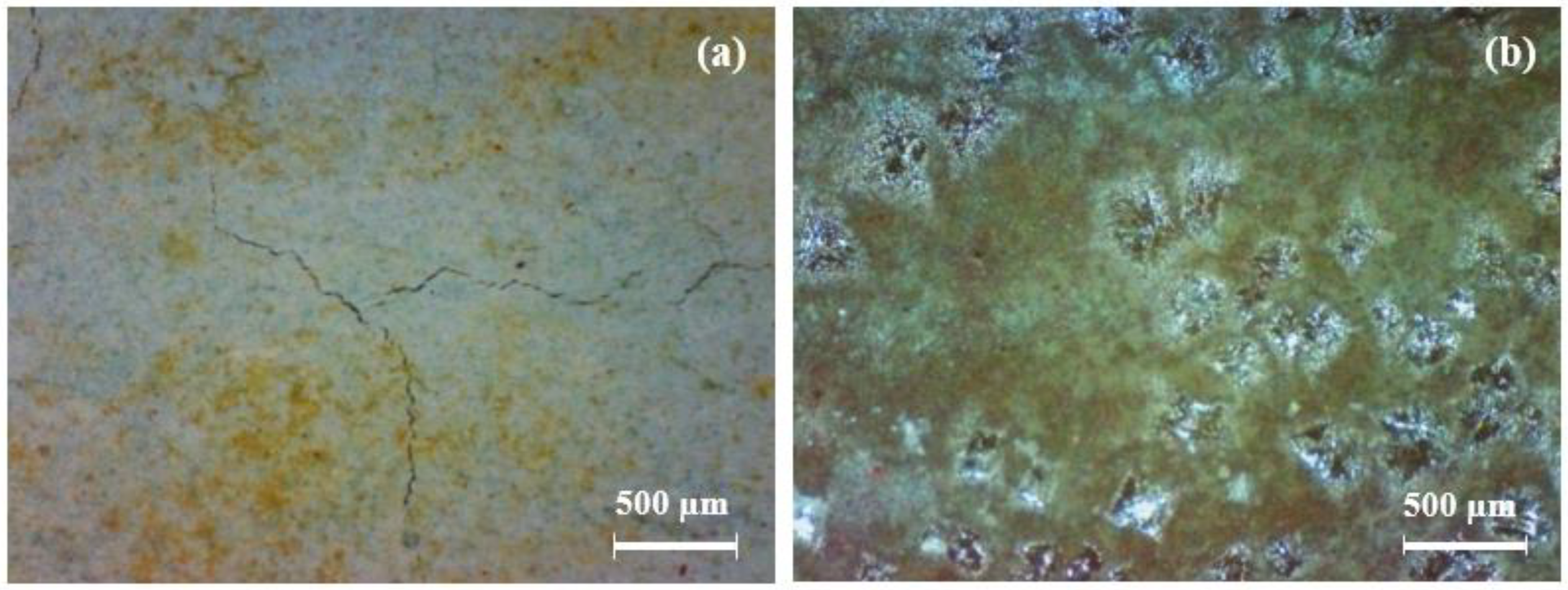
At 1520 d, the coating samples were moved to the 3.5% NaCl solution under an alternating hot and cold temperature condition (45 °C 12 h + 25 °C 12 h). The surface of the coatings gradually presented obvious change. Some micro-cracks and small rust spots were observed at about 1700 d. A portable video digital microscope (Anyty 3R-MSV500, 3R Eddytek Corp, Beijing, China) was applied to observe the surface morphology of the coatings. Figure 2 shows the photos with magnified 200 times. It can be observed that many yellow-green spots are shown on the FW1 coating surface with a few micro-cracks. A few micro-cracks can also be observed on the surface of the FW2 coating, but the central damage forms blisters with green color around the areas. The green color on the coating surface is because, during the immersion process, the copper containing antifouling agents in the topcoat are released and react with the salt water, to produce insoluble cupric salts, which are attached on the surface [6,16,27].

Figure 2.
Photos of (a) FW1 and (b) FW2 coating surface after immersion for 1700 d by a portable video digital microscope.
The EIS spectra of the two coating samples are shown in Figure 3. Figure 3a,b are the Nyquist and Bode (modulus impedance) plots for FW1, and Figure 3c,d for FW2. From the four figures, it can be observed that, before 1520 d immersion at room temperature, no apparent change can be observed in the spectra, and the low-frequency impedance (|Z|0.01Hz) is maintained higher than 1 × 10¹⁰ Ω·cm2, with less than one order of magnitude degreasing from initial value (1 × 10¹¹ Ω·cm2). This indicates that both the anticorrosion and antifouling coating systems have very good permeability resistance to salt water and present excellent barrier performance to the Al alloy substrate. After the alternating hot and cold temperature immersion test for a period, the EIS spectra start to present big changes. The radius of the capacitive loop (Figure 3a,c) and the values of impedance|Z|0.01Hz (Figure 3b,d) for two coating samples decrease rapidly. In Figure 3b, the |Z|0.01Hz value of the FW1 sample decreases to 7 × 10⁵ Ω·cm2 at 1685 d, and decreases continuously to 1 × 10⁵ Ω·cm2 at 1700 d. In Figure 3d, the decreasing amplitude of the |Z|0.01Hz value for FW2 sample is relatively smaller, which is to 2 × 10⁶ Ω·cm2 at 1700 d. The EIS results and the phenomenon of micro-cracks and small blisters observed on the coatings demonstrate that the alternating hot and cold temperature immersion have a remarkable acceleration effect on the failure of the coatings. One possible reason is that the higher temperature can accelerate the diffusion process of the electrolyte within the coating [28], and the other reason is probably related to the build-up of internal stress due to the repeated hot and cold effects of the coating experiences, because the temperature alternation could cause expansion and contraction stresses within the coating, thereby promoting swelling, blistering, or delamination of the coating [28,29]. Thus, the low-frequency impedance decreases rapidly.
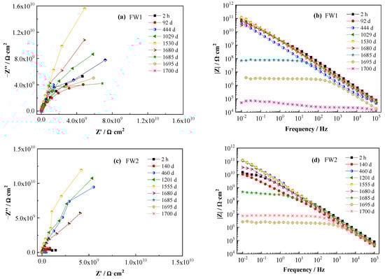
Figure 3.
EIS spectra of two antifouling and anticorrosive coating samples.
3.2. The Microscopic Morphology and Composition Analysis of the Coating Samples
After the 1700 d corrosion test, the microscopic morphologies of the coating surface and cross-section of the coated sample were observed by SEM and the composition was analyzed by EDS. The results are shown in Figure 4 and Figure 5, respectively. Figure 4a shows the surface morphology of the topcoat of FW1 sample. It can be observed that there are many small pores that are not very uniformly distributed. Some of them have the diameters of about 3–4 micro meters. Figure 4b shows the cross-sectional morphology of the FW1 sample. The topcoat looks like it is divided into two layers, in which the inner layer (close to intermediate coat) is still dense, and the outer one (close to the solution) is relatively loose with much more pores, which is called the leached layer in literature [22,30,31]. The formation of the leached layer is because, in the immersion process, when the solution penetrates within the self-polishing topcoat, some water-soluble pigments in the outer layer, including ZnO, Cu2O and CuSCN et al., dissolve preferentially and diffuse through the coating to the electrolyte [31,32,33]; hence, the micro porosities are developed. The looseness or release of the soluble pigments can also accelerate the water diffusion and the failure process of the coating. In this process, the alternating high and cold temperature also has a promoting effect. It is noted that, in the FW1 coating system, the intermediate coat and the primer do not present apparent changes, and both of them still possess a relative intact state. This indicates that though the topcoat has suffered some damages with small pores and micro-cracks, the relative intact intermediate coat and the primer can provide barrier performance to the aluminum alloy substrate. This is in accordance with the above EIS result, in which the impedance |Z|0.01Hz of the coating sample is still not very low (1 × 10⁵ Ω·cm2). EDS tests were performed on the surface of the coating, the cross-section of the leached layer and the inner layer of FW1 topcoat, respectively. Figure 5a is the EDS result of the coating surface. Figure 5b,c are the results of the leached layer and the inner layer. Comparing Figure 5b,c, it can be observed that the Zn content in the loose leached layer is 9.60 wt.%, which is remarkably lower than the Zn content (22.67 wt.%) in the dense inner layer. This might be related with the structural composition of FW1 topcoat, which comprises a high amount of ZnO pigments and a small amount of ZnPT booster biocide, which are dissolved and released after contacting with the solution penetrated in the coating, thereby causing the notable decrease in zinc content in the outer layer of coating. However, because of the very low amount in the coating, ZnPT will not contribute too much. Another possible reason may have a relationship with the zinc acrylate copolymer in the topcoat, in which the ester side groups are easily hydrolyzed and dissolved in saltwater [7,15,34]. The reaction formula is as Formula (2) [14]. The copper content in the leached layer is 21.37 wt.%, and the sulfur content is 11.88 wt.%, which indicates the existence of copper-based agents containing sulfur in the FW1 topcoat. Compared with the contents (23.07 wt.% for copper, and 12.98 wt.% for sulfur) in the inner layer coating, the contents of Cu and S in the leached layer are relatively lower (21.37 wt.% and 11.88 wt.%). This indicates that the CuSCN in the outer layer are released preferentially outward into the solution. In addition, a small amount of the Cl element (2.71 wt.%) is detected in the leached layer, but no Cl in the inner layer is detected, which demonstrated that the Cl element comes from the solution penetration. Comparing Figure 5a,b, it is found that the S content (2.87 wt.%) in the coating surface decreases obviously (from the 11.88 wt.% in the leached layer) and the Cu content (19.72 wt.%) is slightly lower than that (21.37 wt.%) in the leached layer, while the Cl content (10.88 wt.%) increases remarkably. This again confirms the working mechanism of the self-polishing antifouling coating. That is, firstly, the hydrolysis reaction takes place in the acrylic-based resin in the outer layer coating, which contacts with the solution penetrated into the coating, and in the process the water-soluble pigments including soluble antifouling agents are dissolved and released, resulting in some small pores left behind. Gradually, the small pores are connected with each other and become a diffusion path, which can accelerate the species such as Cl− ions in saltwater penetrating into the coating.
| polymer–COO–Zn (s) − X + Na+ ⇋ polymer–COO–Na+ (s) + Zn2+ + X− |
| Zn acrylate (insoluble) acidic polymer (soluble) |

Figure 4.
SEM morphology of FW1 coating sample after 1700 d: (a) the surface of antifouling coating; (b) cross-section of coating sample.
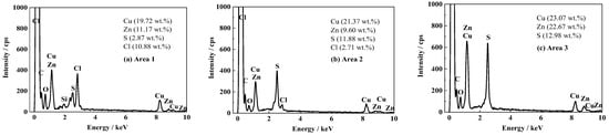
Figure 5.
EDS results of FW1 antifouling coating after 1700 d: (a) the surface of antifouling coating; (b) cross-sectional leached layer of topcoat; (c) cross-sectional inner layer of topcoat.
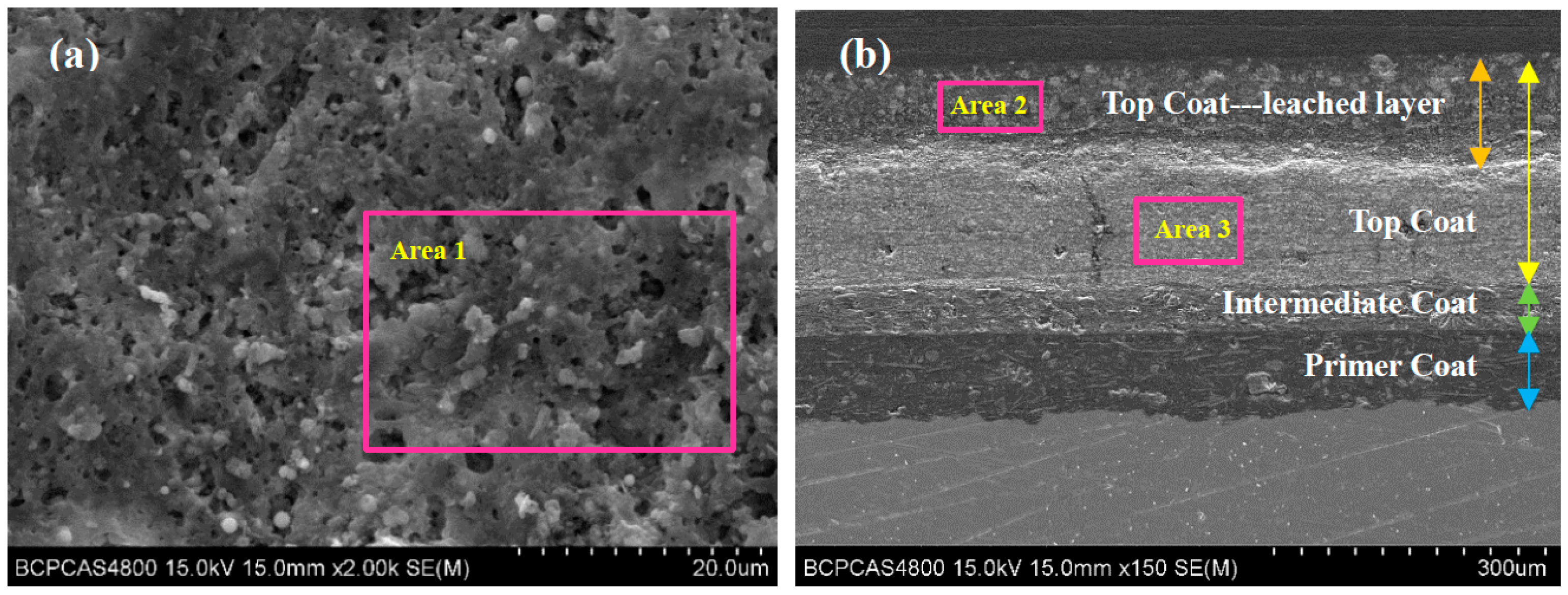
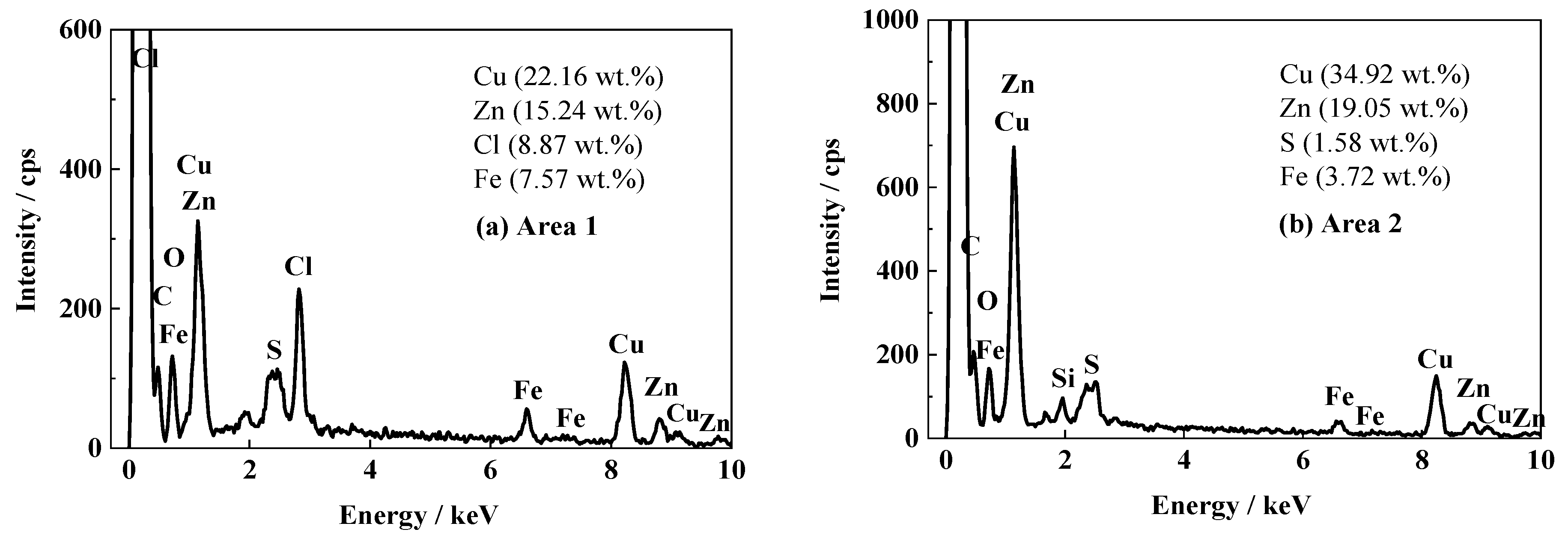
Figure 6 shows the SEM images of the surface and cross-section for the FW2 coating sample after the 1700 d corrosion test. In Figure 6a, many micron-scale pores can be observed, which are distributed uniformly. Most pores possess a diameter of less than 2 micro meters, which are slightly smaller than those in the FW1 topcoat (Figure 4a). The cross-sectional image in Figure 6b shows that in the FW2 topcoat there is also a leached layer formed after the water-soluble pigments dissolution and releasing outward, which confirms the antifouling mechanism. The composition analysis on the FW2 topcoat by EDS is shown in Figure 7. It can be observed that, compared with the Cu content (34.92 wt.%) in the inner layer, the Cu content in the leached layer decreases notably to 22.16 wt.%. It is known that the FW2 topcoat contains a high amount of Cu2O agent, which is a kind of soluble pigment. The Cu2O pigments in the outer layer of the coating react with Cl− ions in the saltwater, producing copper complexed ions of CuCl2− and CuCl32− and releasing into the solution continuously [6,14,35,36]. Therefore, many micron pores are left in the outer layer of the topcoat. The very low content of S (1.58 wt.%) detected in the FW2 topcoat indicates that the main antifouling agents are inorganic copper. Similar to the result of the FW1 coating, the Zn content (15.24 wt.%) in the leached layer of FW2 topcoat is apparently lower than that in the inner layer (19.05 wt.%). This is also resulted from the dissolution of zinc-containing pigments and the hydrolysis reaction of zinc acrylic copolymer after contacting with saltwater. Meanwhile, 8.87 wt.% Cl element is detected in the leached layer, while no Cl is detected in the inner layer. This indicates that the Cl element comes from the NaCl solution penetration. The pores formed after dissolution of the soluble pigments provide a possible diffusion path for the Cl− ions, which can easily penetrate through the leached layer in the coating. This also demonstrates that the outer layer of the topcoat contributes to the decreased impedance and therefore a decreased barrier performance.
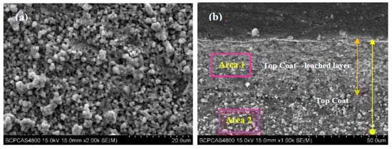
Figure 6.
SEM morphology of FW2 coating sample after test for 1700 d: (a) surface of antifouling coating; (b) cross-section of coating sample.
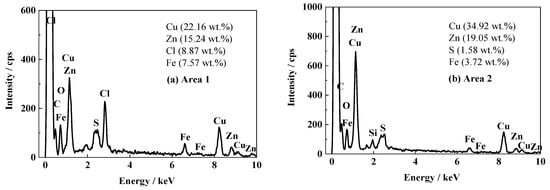
Figure 7.
EDS results of FW2 antifouling coating after 1700 d: (a) cross-sectional leached layer of topcoat; (b) cross-sectional inner layer of topcoat.
The results of SEM/EDS indicate that, after long-term immersion and a period of alternating high and low temperature, the micro morphologies of FW1 and FW2 topcoat experience apparent change, mainly manifested by a leached layer developed after some soluble pigments are hydrolyzed and removed. Comparatively, the micron-scale pores formed in the FW1 topcoat are slightly bigger than those in the FW2 topcoat. The leached layer of FW1 topcoat is much looser with a thickness of 90 μm, which is thicker than that of the leached layer (40 μm) in FW2. This might be related to the different kinds of antifouling agents containing in the two coating systems. It was reported that the solubility, oxidability and particle size distribution of the antifouling pigments all have an impact on the solubilization mechanism [24,37]. Being a principal agent, compared with the agent Cu2O, CuSCN has a little higher solubility in neutral saltwater and with bigger particle size [37]. Thus, for the FW1 topcoat, when the CuSCN particles are dissolved and released, the relatively bigger pores are created. In the FW2 topcoat, the principal antifouling agent is Cu2O. When the Cu2O particles are dissolved, smaller pores are established. With the immersion time prolonged, more pigment particles are dissolved by the NaCl solution, and the reacting zone is slowly extended, which will cause the thickness of the leached layer to increase. It was reported that, in the case of a high water-solubility of the pigments, the large leached layer thickness is easy to establish [35], which is consistent with the results in our work. In addition, when the outer layer of the coating is hydrolyzed and removed, the coating surface changes from hydrophobic to hydrophilic [14] and the mechanical property of the coating becomes worse; therefore, the solution can penetrate into the coating more easily. With the coating hydrolysis and the water ingress proceeding continuously, the antifouling topcoat is gradually dissolved and the thickness is decreased. In parallel with the water uptake, the soluble pigments are dissolved and leached out. Moreover, the looseness and release of the pigments could accelerate the water diffusion and the failure process of the coating [33]; meanwhile, more Cl− ions in the solution penetrate into the leached layer. Due to the relatively loose structure, the blocking effect of the leached layer to the solution decreases significantly. Hence, the barrier property of the anticorrosion and antifouling coating system decreases, because as a topcoat, the antifouling coating is the outermost line of defense. The above EIS results demonstrate that in the later stage of the test (1680~1700 d), the impedance |Z|0.01Hz of the FW2 coating sample is higher than that of the FW1 coating sample. This is in agreement with the SEM result, in which the thickness of the FW2-leached layer (40 μm) is much less than that of the FW1-leached layer (90 μm).
3.3. The Cu Releasing of the Two Coating Samples
ICP-MS was used to obtain the Cu release rate from the antifouling coating. When the FW1 coating sample was immersed up to 600 d, the Cu release rate was 18.8 μg·cm−2·d−1, and the value of FW2 was 24.4 μg·cm−2·d−1. Both of them are higher than the critical release rate copper ion (10 μg·cm−2·d−1) [5,17], which indicates that the FW1 and FW2 topcoats maintained very good antifouling coatings after 600 d immersion in 3.5% NaCl solution at room temperature. After 1500 d immersion, the Cu release rates are decreased to 0.10 and 0.15 μg·cm−2·d−1 for FW1 and FW2, respectively, which indicates that both topcoats basically possess no antifouling effects.
3.4. Infrared Test Results of Two Coating Systems
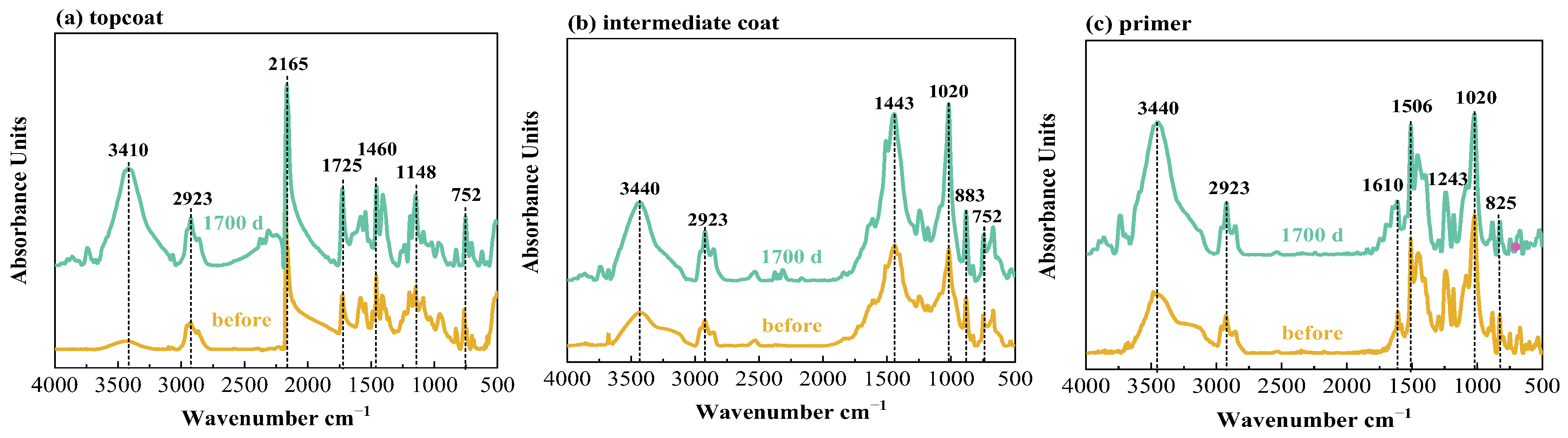
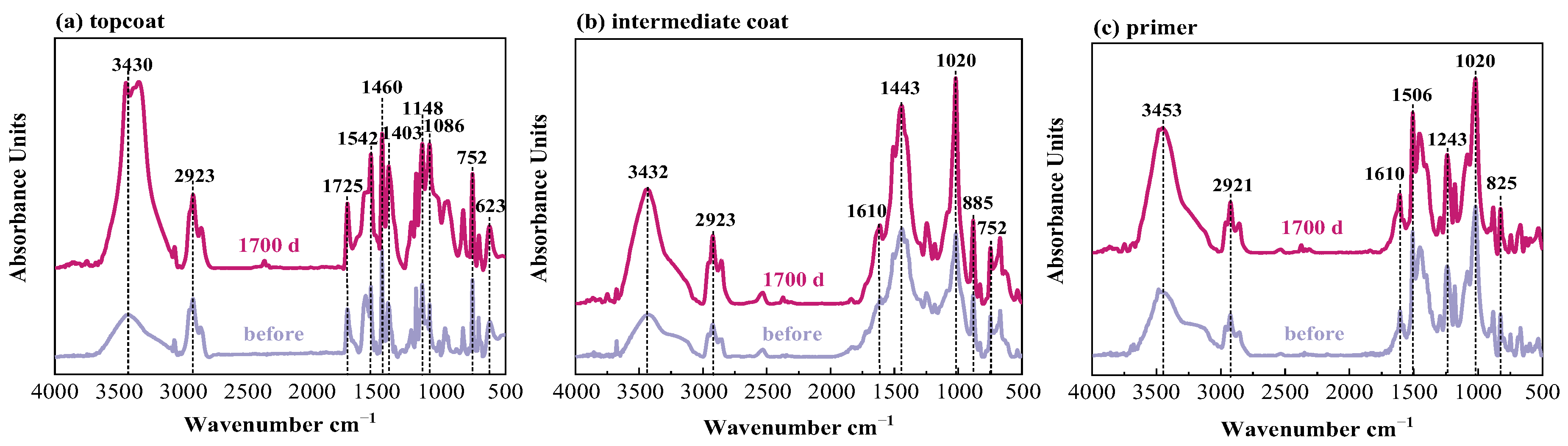
Infrared tests were performed on the topcoat, intermediate coat and primer for FW1 and FW2 samples, respectively, before and after 1700 d corrosion tests. The FTIR results are shown in Figure 8 and Figure 9. Table 2 presents the main bands and the corresponding functional groups in the infrared spectra. It can be observed that, after the 1700 d test, for the FW1 topcoat, the peaks at 3410 and 2165 cm−1 apparently increase in intensity, and the intensity of the peaks at 1725, 1460 (flexural vibration of –CH3) and 1148 cm−1 increase slightly. For the intermediate coat, the intensity of the peaks at 3430, 2923, 1443 and 1020 cm−1 increase to some degree. Other characteristic peaks experience no big change in the intensity. For the primer, except for the increase in the intensity of –OH band, there are no changes for the other bands after the 1700 d test. The FTIR results of the FW1 coating system indicate that obvious hydrolytic degradation occurs on the topcoat and the intermediate coat experiences degradation to some degree, but the degradation degree for the prime is very small.
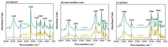
Figure 8.
Infrared spectra of W1 coating system in 3.5% NaCl for different times.
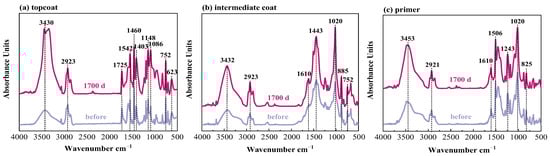
Figure 9.
Infrared spectra of W2 coating system in 3.5% NaCl for different times.
Table 2.
IR band assignments for the primer, intermediate coat and topcoat.
Figure 9 shows the spectra for the FW2 coating sample. In the topcoat, there are no characteristic peaks of the C≡N band in SCN− (2167 cm−1), but the peaks at 623 cm−1 (Cu–O) are detected. This confirms that the FW2 topcoat contains a Cu2O antifouling agent and no CuSCN agent. The comparison between the spectra before and after the immersion test shows that, similar to the FW1 coating system, the topcoat and intermediate coat in FW2 system experience hydrolytic degradation to different degrees, and no obvious degradation occurs in the prime coat. The FTIR test results are consistent with the above SEM result.
4. Conclusions
This work was performed to comparatively study the effect of two antifouling agents (CuSCN and Cu2O) releasing on the self-polishing coating failure and therefore the protective performance of the anticorrosion and antifouling coating systems to the 5083 Al alloy substrate. The hydrolysis degradation behavior of the two coatings was investigated by SEM/EDS and FTIR methods, and the electrochemical behavior was studied by the EIS test. The main conclusions are as follows.
(1) After immersion in 3.5% NaCl solution at room temperature for more than four years, two anticorrosion and antifouling coating systems still have very good protection property for the 5083 Al alloy substrate, manifested by high impedance |Z|0.01Hz. Alternate high and low temperature immersion (3.5% NaCl solution, 45 °C 12 h + 25 °C 12 h) accelerates the degradation process of the coatings, causing many micro-pores and micro-cracks on the antifouling topcoats, and the impedance |Z|0.01Hz of the coating samples decreases remarkably.
(2) During water absorption and the hydrolysis degradation process of the antifouling topcoat, the copper-contained antifouling agents are dissolved and released. For the topcoat containing the CuSCN agent, after the CuSCN particles are dissolved and released, some relatively bigger micro-pores are created and a looser and thick leached layer is formed. For the topcoat containing the Cu2O agent, when the Cu2O particles are dissolved, smaller pores are established with a relatively thinner leached layer. The barrier property of the coating system with the CuSCN-containing topcoat is lower than that with the Cu2O agent. This may be related with the slightly bigger solubility and particles’ diameter of CuSCN than Cu2O.
Author Contributions
Writing—original draft and investigation, H.Z. and J.C.; Characterization and data analysis, L.S., F.K. and J.T.; Supervision, Writing—review and editing, Y.T.; Methodology, data analysis guiding, Writing—review and editing, X.Z. and Y.Z. All authors have read and agreed to the published version of the manuscript.
Funding
This research received no external funding.
Institutional Review Board Statement
Not applicable.
Informed Consent Statement
Not applicable.
Data Availability Statement
Not applicable.
Conflicts of Interest
The authors declare no conflict of interest.
References
- Liu, C.; Ma, C.F.; Xie, Q.Y.; Zhang, G.Z. Self-repairing silicone coatings for marine anti-biofouling. J. Mater. Chem. A 2017, 5, 15855–15861. [Google Scholar] [CrossRef]
- Chambers, L.D.; Stokes, K.R.; Walsh, F.C.; Wood, R.J.K. Modern approaches to marine antifouling coatings. Surf. Coat. Technol. 2006, 201, 3642–3652. [Google Scholar] [CrossRef]
- Paz-Villarraga, C.A.; Castro, Í.B.; Fillmann, G. Biocides in antifouling paint formulations currently registered for use. Environ. Sci. Pollut. Res. 2022, 29, 30090–30101. [Google Scholar] [CrossRef]
- Detty, M.R.; Ciriminna, R.; Bright, F.V.; Pagliaro, M. Environmentally benign sol-gel antifouling and foul-releasing coatings. Acc. Chem. Res. 2014, 47, 678–687. [Google Scholar] [CrossRef] [PubMed]
- Fu, Y.; Du, H.; Chen, Z.J.; Liu, X.; Zhang, X.D. Preparation and performance of new antifouling resins containing BIT group. J. Adhes. Sci. Technol. 2019, 33, 93–109. [Google Scholar] [CrossRef]
- Yu, X.Y.; Wang, K.; Chen, Z.T.; Yu, H.J.; Xiao, L.; Gui, T.J. Research on leaching rate & degradation behavior of Cu2O contained in antifouling paints. Paint. Coat. Ind. 2012, 42, 45–52. (In Chinese) [Google Scholar]
- Bressy, C.; Hellio, C.; Nguyen, M.N.; Tanguy, B.; Maréchal, J.; Margaillan, A. Optimized silyl ester diblock methacrylic copolymers: A new class of binders for chemically active antifouling coatings. Prog. Org. Coat. 2014, 77, 665–673. [Google Scholar] [CrossRef]
- Grunnet, K.S.; Dahllöf, I. Environmental fate of the antifouling compound zinc pyrithione in seawater. Environ. Toxicol. Chem. 2005, 24, 3001–3006. [Google Scholar] [CrossRef]
- Cima, F.; Varello, R. Potential disruptive effects of copper-based antifouling paints on the biodiversity of coastal macrofouling communities. Environ. Sci. Pollut. Res. 2022. [Google Scholar] [CrossRef]
- Hunsucker, K.Z.; Gardener, H.; Lieberman, K.; Swain, G. Using hydrodynamic testing to assess the performance of fouling control coatings. Ocean Eng. 2019, 194, 106677. [Google Scholar] [CrossRef]
- Punitha, N.; Saravanan, P.; Mohan, R.; Ramesh, P.S. Antifouling activities of β-cyclodextrin stabilized peg based silver nanocomposites. Appl. Surf. Sci. 2017, 392, 126–134. [Google Scholar] [CrossRef]
- Bressy, C.; Margaillan, A. Erosion study of poly(trialkylsilyl methacrylate)-based antifouling coatings. Prog. Org. Coat. 2009, 66, 400–405. [Google Scholar] [CrossRef]
- Tribou, M.; Swain, G. The effects of grooming on a copper ablative coating: A six year study. Biofluling 2017, 33, 494–504. [Google Scholar] [CrossRef] [PubMed]
- Yebra, D.M.; Kiil, S.; Johansen, K.D. Antifouling technology−past, present and future steps towards efficient and environmentally friendly antifouling coatings. Prog. Org. Coat. 2004, 50, 75–104. [Google Scholar] [CrossRef]
- Bressy, C.; Hugues, C.; Margaillan, A. Characterization of chemically active antifouling paints using electrochenmical impedance spectrometry and erosion tests. Prog. Org. Coat. 2009, 64, 89–97. [Google Scholar] [CrossRef]
- Faÿ, F.; Horel, G.; Linossier, I.; Vallée-Réhel, K. Effect of biocidal coatings on microfouling: In vitro and in situ results. Prog. Org. Coat. 2018, 114, 162–172. [Google Scholar] [CrossRef]
- Valkirs, A.O.; Seligman, P.F.; Hasleck, E.; Caso, J.S. Measurement of copper release rates from antifouling paint under laboratory and in situ conditions: Implications for loading estimation to marine water bodies. Mar. Pollut. Bull. 2003, 46, 763–779. [Google Scholar] [CrossRef]
- Dai, Z.W.; Cao, M.; Li, S.Q.; Yao, J.H.; Wu, B.; Wang, Y.P.; Wang, H.J.; Dong, J.; Yi, J. A novel marine antifouling coating based on a self-polishing zinc-polyurethane copolymer. J. Coat. Technol. Res. 2021, 18, 1333–1343. [Google Scholar] [CrossRef]
- Wang, S.; Liu, X.J.; Yu, L.M.; Zhao, Y.; Sun, M.L. Low surface energy self-polishing polymer grafted MWNTs for antibacterial coating and controlled-release property of Cu2O. J. Appl. Polym. 2021, 138, 50267. [Google Scholar] [CrossRef]
- Turley, P.A.; Fenn, R.J.; Ritter, J.C.; Callow, M.E. Pyrithiones as antifoulants: Environmental fate and loss of toxicity. Biofouling 2005, 21, 31–40. [Google Scholar] [CrossRef]
- Pavlacky, D.A.; Gelling, V.J.; Ulven, C.A. The use of electrochemical impedance spectroscopy to monitor delaminations in polymer matrix composites: A review. Int. J. Mater. Sci. 2011, 1, 23–29. [Google Scholar] [CrossRef]
- Peres, R.S.; Armelin, E.; Moreno-Martínez, J.A.; Alemán, C.; Ferreira, C.A. Transport and antifouling properties of papain-based antifouling coatings. Appl. Surf. Sci. 2015, 341, 75–85. [Google Scholar] [CrossRef]
- Thomas, K.A.; Nair, S.; Rajeswari, R.; Ramesh Kumar, A.V.; Natarajan, V.; Mukunda, T.; John, R. Electrochemical behaviour of PANi/polyurethane antifouling coating in salt water studied by electrochemical impedance spectroscopy. Prog. Org. Coat. 2015, 89, 267–270. [Google Scholar] [CrossRef]
- Chasse, K.R.; Scardino, A.J.; Swain, G.W. Corrosion and fouling study of copper-based antifouling coatings on 5083 aluminum alloy. Prog. Org. Coat. 2020, 141, 105555. [Google Scholar] [CrossRef]
- Zhu, B.F.; Liu, Z.H.; Liu, J.; Yang, Y.M.; Meng, Y.B.; Yu, F.; Jiang, L.; Wei, G.Y.; Zhang, Z. Preparation of fluorinated/silanized polyacrylates amphiphilic polymers and their anticorrosion and antifouling performance. Prog. Org. Coat. 2020, 140, 105510. [Google Scholar] [CrossRef]
- GB/T 6824-2008; Determination for Release Rate of Cupper-Ion for Antifouling Paint on Ship Bottom. GB/T: Beijing, China, 2008. (In Chinese)
- Champ, M.A. A review of organotin regulatory strategies, pending actions, related costs and benefits. Sci. Total Environ. 2000, 258, 21–71. [Google Scholar] [CrossRef]
- Touzain, S.; Thu, Q.L.; Bonnet, G. Evaluation of thick organic coatings degradation in seawater using cathodic protection and thermally accelerated tests. Prog. Org. Coat. 2005, 52, 311–319. [Google Scholar] [CrossRef]
- Perrin, F.X.; Merlatti, C.; Aragon, E.; Margaillan, A. Degradation study of polymer coating: Improvement in coating weatherability testing and coating failure prediction. Prog. Org. Coat. 2009, 64, 466–473. [Google Scholar] [CrossRef]
- Olsen, S.M.; Pedersen, L.T.; Hermann, M.H.; Kiil, S.; Dam-Johansen, K. Inorganic precursor peroxides for antifouling coatings. J. Coat. Technol. Res. 2009, 6, 187–199. [Google Scholar] [CrossRef]
- KiiL, S.; Dam-Johansen, K. Characterization of pigment-leached antifouling coatings using BET surface area measurements and mercury porosimetry. Prog. Org. Coat. 2007, 60, 238–247. [Google Scholar] [CrossRef]
- Yebra, D.M.; KiiL, S.; Weinell, C.E.; Dam-Johansen, K. Dissolution rate measurements of sea water soluble pigments for antifouling paint: ZnO. Prog. Org. Coat. 2006, 56, 327–337. [Google Scholar] [CrossRef]
- Tian, W.L.; Meng, F.D.; Liu, L.; Li, Y.; Wang, F.H. The failure behaviour of a commercial highly pigmented epoxy coating under marine alternating hydrostatic pressure. Prog. Org. Coat. 2015, 82, 101–112. [Google Scholar] [CrossRef]
- Yonehara, Y.; Yamashita, H.; Kawamura, C.; Iton, K. A new antifouling paint based on a zinc acrylate copolymer. Prog. Org. Coat. 2001, 42, 150–158. [Google Scholar] [CrossRef]
- Kiil, S.; Dam-Johansen, K.; Weinell, C.E.; Pedersen, M.S. Seawater-soluble pigments and their potential use in self-polishing antifouling paints: Simulation-based screening tool. Prog. Org. Coat. 2002, 45, 423–434. [Google Scholar] [CrossRef]
- Almeida, E.; Diamantino, T.C.; Sousa, O. Marine paints: The particular case of antifouling paints. Prog. Org. Coat. 2007, 59, 2–20. [Google Scholar] [CrossRef]
- Vetere, V.F.; Pérez, M.C.; Romagnoli, R.; Stupak, M.E.; Amo-Cidepint, B.D. Solubility and toxic effect of the cuprous thiocyanate antifouling pigment on barnacle larvae. J. Coat. Technol. 1997, 69, 39–45. [Google Scholar] [CrossRef]
- Ammar, S.; Ramesh, K.; Azman, N.A.N.; Vengadaesvaran, B.; Ramesh, S.; Arof, A.K. Comparison studies on the anticorrosion and overall performance of solvent/water based epoxy-copper reinforced composite coatings. Mater. Express 2016, 6, 403–413. [Google Scholar] [CrossRef]
- Karadeniz, K.; Çalıkoğlu, Y.; Sen, M.Y. A novel polyurethanes from epoxidized soybean oil synthesized by ring opening with bifunctional. Polym. Bull. 2017, 74, 2819–2839. [Google Scholar] [CrossRef]
- Matin, E.; Attar, M.M.; Ramezanzadeh, B. Investigation of corrosion protection properties of an epoxy nanocomposite loaded with polysiloxane surface modified nanosilica particles on the steel substrate. Prog. Org. Coat. 2015, 78, 395–403. [Google Scholar] [CrossRef]
- Samui, A.B.; Chavan, J.G.; Hande, V.R. Study on film forming organo-copper polymer. Prog. Org. Coat. 2006, 57, 301–306. [Google Scholar] [CrossRef]
- Yang, H.F.; Sheng, X.M.; Li, Y.C.; Xiao, F.J. Preparation of cuprous thiocyanate nanoparticles for marine antifouling paint. J. Chin. Ceram. Soc. 2006, 34, 1456–1460. (In Chinese) [Google Scholar]
- Silva, E.R.; Ferreira, O.; Ramalho, P.A.; Azevedo, N.F.; Bayón, R.; Igartua, A.; Bordado, J.C.; Calhorda, M.J. Eco-friendly non-biocide-release coatings for marine biofouling prevention. Sci. Total Environ. 2019, 650 Pt 2, 2499–2511. [Google Scholar] [CrossRef] [PubMed]
- Perrin, F.X.; Irigoyen, M.; Aragon, E.; Vernet, J.L. Evaluation of accelerated weathering tests for three paint systems: A comparative study of their aging behaviour. Polym. Degrad. Stab. 2001, 72, 115–124. [Google Scholar] [CrossRef]
- Yang, X.F.; Vang, C.; Tallman, D.E.; Bierwagen, G.P.; Croll, S.G.; Rohlik, S. Weathering degradation of a polyurethane coating. Polym. Degrad. Stab. 2001, 74, 341–351. [Google Scholar] [CrossRef]
- Mao, T.Y.; Lu, G.; Xu, C.Y.; Yu, H.W.; Yu, J.L. Preparation and properties of polyvinylpyrrolidone-cuprous oxide microcapsule antifouling coating. Prog. Org. Coat. 2020, 141, 105317. [Google Scholar] [CrossRef]


Publisher’s Note: MDPI stays neutral with regard to jurisdictional claims in published maps and institutional affiliations. |
© 2022 by the authors. Licensee MDPI, Basel, Switzerland. This article is an open access article distributed under the terms and conditions of the Creative Commons Attribution (CC BY) license (https://creativecommons.org/licenses/by/4.0/).