Article

The Model for Estimating the Failure Mechanism of Tensioned Plasma-Sprayed Zirconia Ceramic Hard Coating

1
G.S. Pisarenko Institute for Problems of Strength, National Academy of Sciences of Ukraine, 2 Timiryazevska Street, 01014 Kyiv, Ukraine
2
Department of Manufacturing, Repair and Materials Engineering, National Transport University, 1 Omelianovycha-Pavlenka Street, 01010 Kyiv, Ukraine
3
Latvian Maritime Academy, Flotes Street 12 k-1, LV-1016 Riga, Latvia
4
Institute of Aeronautics, Riga Technical University, 1 Lomonosova Street, LV-1019 Riga, Latvia
*
Author to whom correspondence should be addressed.
Coatings 2022, 12(8), 1175; https://doi.org/10.3390/coatings12081175
Submission received: 18 July 2022 / Revised: 3 August 2022 / Accepted: 10 August 2022 / Published: 14 August 2022
(This article belongs to the Section Plasma Coatings, Surfaces & Interfaces)

Abstract

:
Loading flat coated specimens with tensile forces is a universal method to determine the nature of fracture of hard coatings in maritime applications. Such an approach allows the determination of the shear strength at the interfaces between layers and the cohesive properties. Thus, the authors studied the fracturing processes of plasma-sprayed yttria-stabilized zirconia two-layer coatings under the action of tensile forces. The results revealed cracking characteristics in the outer ceramic layer and delamination of flat metal specimens. An analytical method led to normal stress determination in the coating. It also exhibited shear stresses at the bond coat-substrate interface and the top coat-bond coat interfaces. The results include normal and shear stress distributions before and after fragmentation of the ceramic top layer. Tested substrate, the metal bond coat, and the ceramic top coat exhibit a modulus of elasticity of 196, 142, and 47 GPa, respectively. Engineers could apply the proposed methodology and the mathematical analysis to study the causes of cracks and delamination between layers.

Graphical Abstract

1. Introduction

Manufacturers commonly use alloy 08Kh18N10 (GOST) and its equivalent AISI 304 to produce welded elements using typical arc welding processes. Tungsten inert gas, metal inert gas, manual metal arc welding, and submerged arc welding are some examples of arc welding. Thermal power plants expose elements made of 08Kh18N10 and AISI 304 stainless steel sheets to hot, corrosive, and oxidative environments under high pressure, combined with mechanical stresses and impacts. These factors lead to accelerated corrosion, damage, and fracture of the affected stainless steel technical parts [1]. Protective coatings are widely applied to stainless steel boiler parts to reduce corrosion and erosion. Engineers have developed many thermal barrier coatings (TBCs) and suitable coating techniques using various thermal spray techniques, such as plasma spraying, high-velocity oxygen spraying, detonation spraying, etc. [2,3]. TBCs are brittle materials subjected to severe thermomechanical conditions. These coatings require a metallic interlayer to ensure adequate adhesion during service [4].
The austenitic nature of 08Kh18N10 and AISI 304 has numerous applications in marine engineering. These applications include springs, nuts, bolts and screws, marine equipment, nuclear vessels, fasteners, and oil and cryogenic gas storage facilities [5]. These steels exhibit higher electrical and thermal conductivity. Therefore, using protective and thermal barrier coatings ensures adequate durability under expected operational conditions [6]. In addition, due to their non-magnetic properties, these steels are suitable for transporting magnetic and ferromagnetic materials. These materials can be magnets containing devices or elements, residual metal particles from cutting or welding processes (industrial waste) [7], ferrofluids [8], etc., which otherwise can contaminate cargo tanker walls.
Engineers widely use plasma spraying to realize different advanced solutions: starting from composite powders [9,10], corrosive protection [11], tribo-resistive coatings [12], and produce suitable hard ceramic-coated tools. These tools closely matched the final design of softer substrates for applications in various mechanical engineering and medicine fields [13]. For example, yttria-stabilized tetragonal zirconia performs high wear and corrosion resistance. These properties are combined with a heat-shielding thermal barrier [14] and biomedical adaptability [15,16,17], as shown in Table 1.
Zirconia exhibits good wear resistance and a low coefficient of friction in sliding contacts with hard-coated counter-bodies at low operating temperatures [18]. The crystalline structure of zirconia can transform between monoclinic, tetragonal, and cubic phases at temperatures of 1200 and 2370 °C [14]. Such temperatures can also be achieved by flash during high-speed sliding against another hard counter-body at elevated temperatures. However, such hard coatings exhibit poor adhesion to structurally dissimilar substrates and may even prevent any coating technique from forming a stable layer. Implementing a plasma-sprayed metal sublayer (adhesion layer) of the mono-, multi-, or gradient type [18,23] is one of the most reliable approaches to increase the adhesion strength of the ceramic coating on steel substrates. Targeted multi- and gradient-type adhesion coatings usually provide better adhesion on a softer substrate and a hard coating on the opposite side. However, tailored coatings require a more complex coating structure and approach to achieve uniform properties on complex-shaped targets. Therefore, single-layer metal undercoating remains a cost-effective and affordable solution for coating applications. In the meantime, reliability issues may still need research and development for use on different materials under different conditions.
Nickel-based NiCoCrAlY alloy is one of the candidates for single-layer composite coatings between ductile steels and hard-body thermal barrier coatings (TBCs) such as zirconia [24,25,26]. Thermal spray deposition is one of this alloy’s most used methods. This type of coating helps to protect complex-shaped components, such as modern gas turbine engines and welded compartments made of corrosion-resistant high-temperature steels. The presence of Ni and Cr in the NiCoCrAlY alloy provides structural similarity to most high-temperature steels due to the high content of Ni or Cr. Sufficient adhesion, high elastic modulus, increased mechanical strength, and good oxidation behavior combined with the increased hardness of up to 6.2 GPa due to the presence of Y (see Table 2) provide the required transition of structural properties from the steel substrate to the hard surface layer [27]. The solid solution hardening caused by yttrium is crucial in improving adhesion to TBCs at low concentrations of 0.1 wt.% up to 1 wt.%. In addition, a uniform yttrium distribution in the material positively affects the adhesion of the formed oxides in γ/β MCrAlY coatings [28] in oxidative environments.
Cobalt significantly reduces dislocation motion through grain boundaries and provides creep resistance of NiCoCrAlY solid solutions over a long period when subjected to high stresses [32]. Furthermore, the aluminum content of 8 wt.% to 15 wt.% in the solid solution reduces the growth rate of the crystalline phase [33], mainly composed of α-Al2O3. This effect relates to the much higher melting temperature of NiCoCrAlY (1330 °C) than the transformation temperature of the α-alumina phase of 1150 °C. This effect leads to a thermally stable and uniformly distributed continuous aluminum-rich oxide layer, which provides good adhesion properties inside the alloy and in contact with the ductile substrate and the brittle ceramic hard coating [34,35].
The properties of plasma-sprayed coatings depend primarily on the feedstock powders’ structure, composition, and morphology. In addition, the final porosity, microcracks, and macrocracks depend on the selected plasma spraying conditions, as well as on the design and performance of the equipment [36]. One of the most important reasons for the collapse and failure of technological elements is the cracking of the hard coating in flakes and delamination from the substrate or adhesive layer under the applied operating conditions [37]. The delaminated hard particles can lead to high abrasive wear of tools in sliding contact and cause additional pinholes in the hard coating due to mechanical stressing by the counter-body [38]. Such damage typically increases the permeability of the corrosive medium (e.g., salt water) [23,39,40]. This process can lead to severe pitting corrosion and additional stress on the hard coating from the substrate side due to swelling of corrosion products (e.g., metal hydroxides and complexes) [41]. In this context, engineers should investigate the strength properties, delamination, and cracking of two-layer coatings to increase the reliability of plasma-sprayed hard coatings. Additionally, experience-based recommendations for improving materials and process design are required.
Loading flat coated specimens with tensile forces is a universal method to determine the nature of fracture of hard coatings [42]. Such an approach allows the determination of the shear strength at the interfaces between coatings and the cohesive properties [43]. Engineers have developed several analytical techniques to evaluate layered material’s stress states in planar [44,45,46,47,48] and cylindrical models [42,43]. Numerical methods for estimating the stress state of layered materials are also widely used and allow the calculation of more complicated structural components [48,49].
The present article demonstrates the analysis of shear and normal stresses obtained by the analytical approach on the example of two-layer plasma-sprayed coatings. Ceramic hard coatings fracture by different mechanisms in service and under testing conditions. The authors studied the fracture mechanism of a hard coating under tensile loading on a metal substrate. In addition, the authors considered the mechanism of damage assessment and destruction of the upper ceramic coating during tensile tests. The proposed approach allows for the evaluation of the nature and damage features of two-layer coatings in ambient and corrosive maritime environments.

2. Materials and Methods

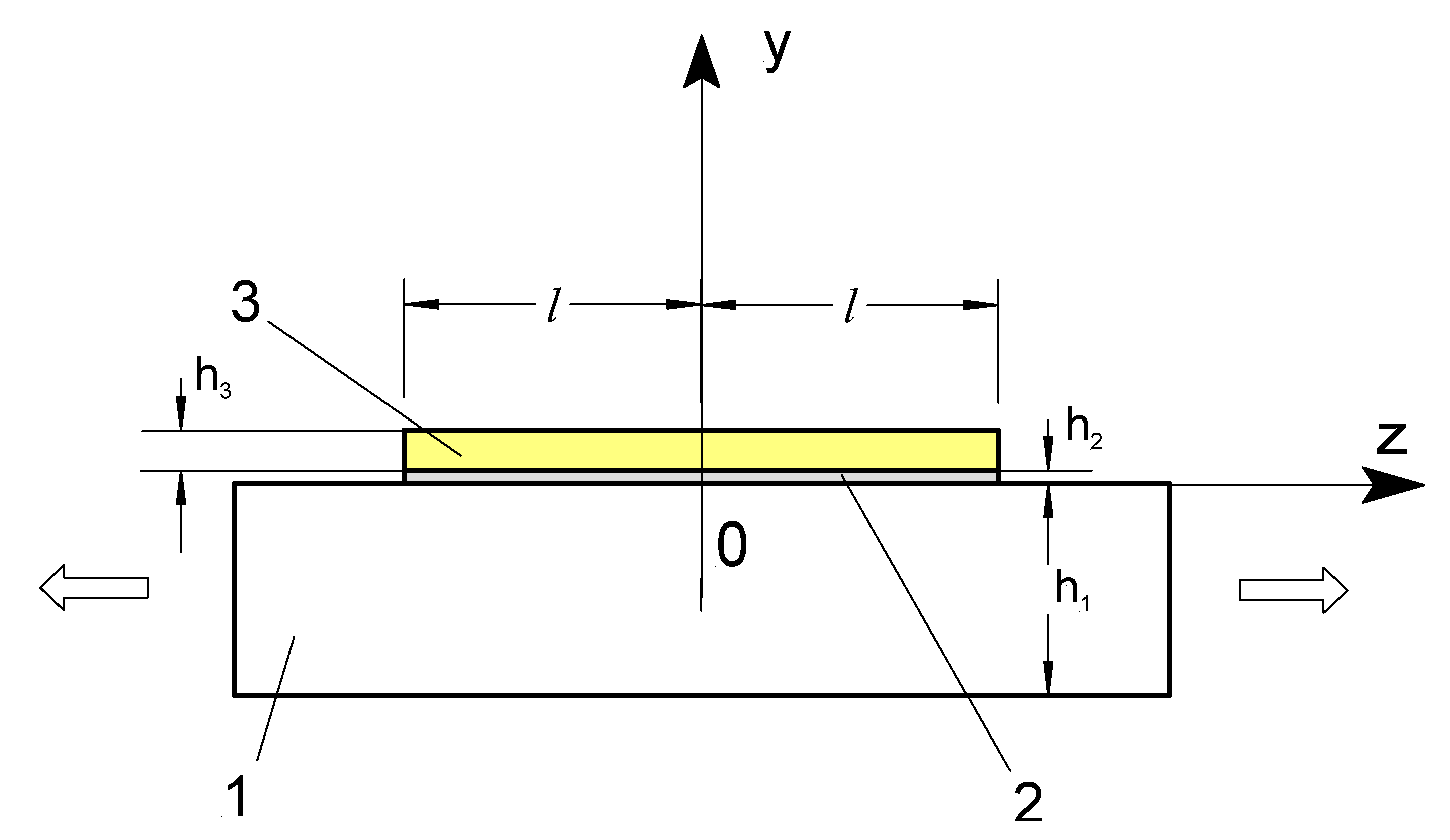
2.1. Applied Model for the Determination of the Stress–Strain State in a Two-Layer Coating

When subjected to an external load, an inhomogeneous stress-strain state occurs in two-layer coatings. This effect relates to the different properties of the coating and the substrate. Therefore, engineers must consider the properties of multilayer materials in the design and construction of coated components. The derivation of analytical equations that allow the determination of normal and shear stresses in a bilayer coating under applied tensile load to the substrate was already presented [50]. The coated substrate is subjected to a tensile load according to the developed model, as shown in Figure 1. In this model, tensile forces stress the substrate 1. The coating consists of the adhesion promoter 2 and the top ceramic layer 3. The shear stress 1 occurs in the substrate and adhesion promoter interfaces. At the same time, shear stress 2 appears in the interface between the adhesion promoter and ceramic top layer. The method for estimating the strength properties of ceramic top coats is based on static short-time tensile tests on coated specimens. The authors prepared the metal specimens for tensile tests according to the standard ISO 6892-1. A standardized computer-controlled Instron tensile testing machine (for forces up to 10 kN and loading rates from 10 up to 90 mm·min−1) performed the strain tests and provided comparability of the test results. The operator performed tensile testing at ambient temperature. Strain gauges measured the strains on the surface of the specimens. The tensile process of the specimens was conducted intermittently. The device detected the failure of the coating by monitoring strain gauge indication drops.
During the loading process of the specimens, the tensile testing machine continuously measured the strains and the corresponding tensile forces. In addition, strain gauges provided deformation measurements. Finally, the operator determined the strains of the specimens by the tensile testing machine grip displacements after the destruction of the strain gauges. Additionally, the authors applied elastic modulus determination methods [43,51] to the bottom and top layers of the coating.
The shear stresses τ1(z) and τ2(z) are determined according to the following criteria, as shown in Equations (1) and (2) [50]:
τ 1 ( z ) = S 1 cos 2 β ε 0 sin h ( k 1 z ) k 1 cos h ( k 1 l ) + S 1 sin 2 β ε 0 sin h ( k 2 z ) k 2 cos h ( k 2 l ) ,  
τ 2 ( z ) = S 1 S 2 sin β cos β ε 0 sin h ( k 1 z ) k 1 cos h ( k 1 l ) S 1 S 2 sin β cos β ε 0 sin h ( k 2 z ) k 2 cos h ( k 2 l ) ,  
where the coefficients S1, S2, β, k1, k2 were determined earlier and are shown in [50], ε0 is the substrate strain, h is the thickness, l is the characteristic size in the direction collinear to the action of principal stresses, and z is cross section along z axis.
Coefficients S1 and S2 were similarly determined using to the approach [52] when the thickness of the surface layer of the substrate subjected to shear is equal to h1/2, as shown in Equation (3):
S 1 = 2 ( h 1 G 1 + h 2 G 2 ) 1 ; S 2 = 2 ( h 2 G 2 + h 3 G 3 ) 1
The normal stresses σ2(z) in bond coat 2 (Equation (4) and the normal stresses σ3(z) in the top ceramic layer 3 (Equation (5)) are equal:
σ 2 = N 2 F 2 ;
σ 3 = N 3 F 3 ,
where N2, N3 are the longitudinal forces in the bond coat 2 and the top ceramic layer 3, respectively.
The longitudinal forces are expressed by Equations (6) and (7):
N2 = Q1Q2;
N3 = Q2,
where Q1 and Q2 are shear forces expressed by Equations (8) and (9):
Q 1 = S 1 t cos 2 β ε 0 k 1 2 ( cos h ( k 1 z ) cos h ( k 1 l ) 1 ) + S 1 t sin 2 β ε 0 k 2 2 ( cos h ( k 2 z ) cos h ( k 2 l ) 1 )
Q 2 = S 1 S 2 t sin β cos β ε 0 k 1 2 ( cosh ( k 1 z ) cosh ( k 1 l ) 1 ) S 1 S 2 t sin β cos β ε 0 k 2 2 ( cosh ( k 2 z ) cosh ( k 2 l ) 1 )

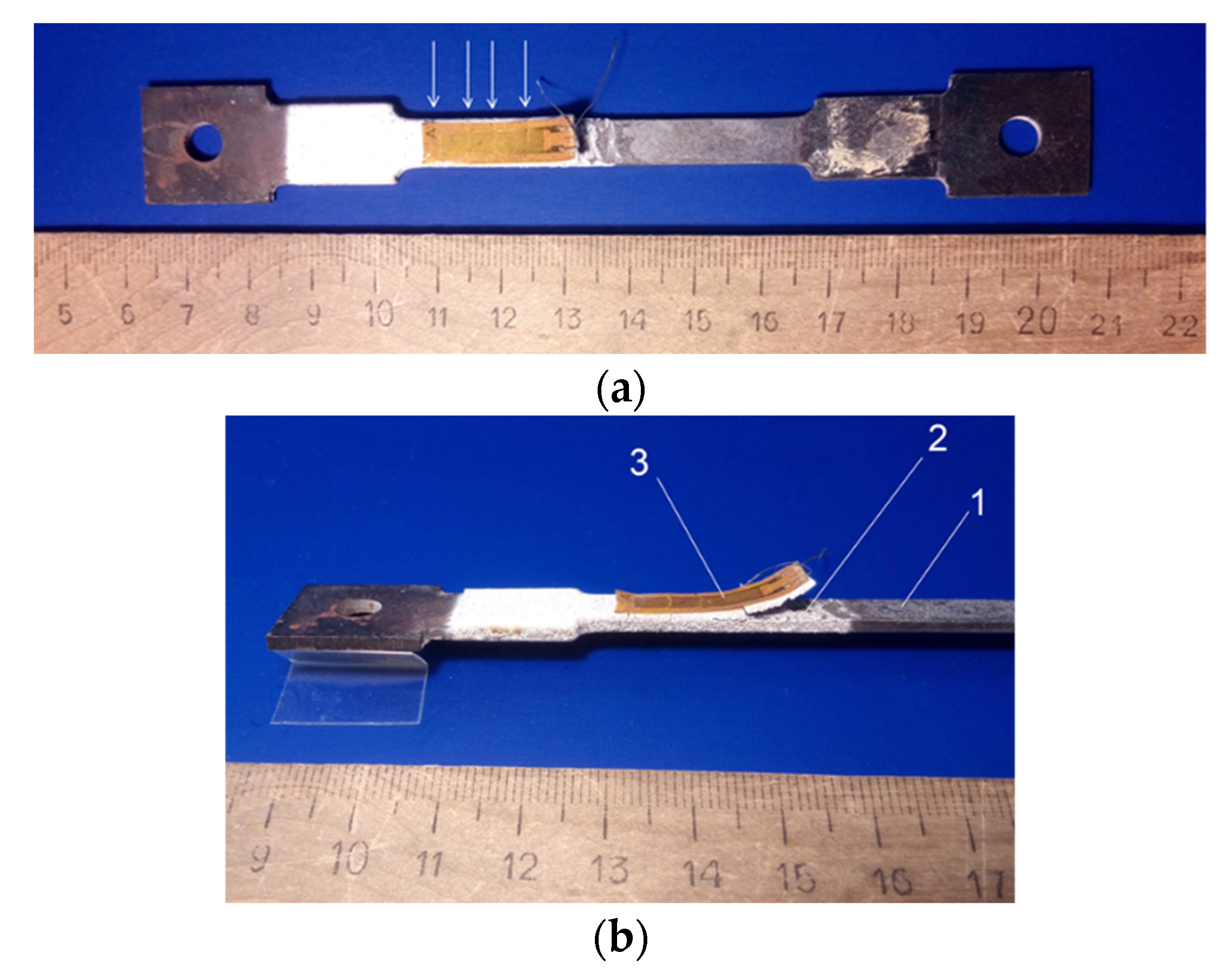
2.2. Applied Materials, Equipment and Conditions

The operator produced samples of two-layer coatings with the help of plasma spraying on flat metal specimens. First, an operator prepared and tested three specimens and prepared one specimen for results control needs. The substrate consisted of corrosion and heat-resistant stainless steel 08Kh18N10 (analogous to AISI 304) with a thickness of 1.8 mm. Before spraying the metal layer, the operator grounded the sample’s surface with corundum to the roughness of Ra from 6 up to12 μm (measured according to DIN EN ISO 4287 with a Mahr Perthometer, PGK 120, Mahr GmbH, Göttingen, Germany, contact mode). Next, a Co-32%Ni-21%Cr-8%Al-0.5%Y powder AMDRY 995C with a particle size of 45 to 75 μm was used to plasma spray the adhesive layer with a thickness of 100 μm (measured using a caliper gauge). Finally, the top coat consisted of plasma-sprayed Metco 204C NS powder with a composition of ZrO2-8% Y2O3. Used ceramic particles had sizes from 45 μm up to 125 μm.
The thickness of the ceramic top coat was 200 μm (measured using a caliper). The operator used a UPU 3D (УПУ-3Д, made in USSR) plasma spraying system to apply the coating with the help of the plasma-forming gas consisting of argon and hydrogen. Additionally, the operator customized spray conditions for producing the bond coat and the top coat, as demonstrated in Table 3.

3. Results

3.1. Estimation of Strength Properties of Ceramic Coatings

The measured modulus of elasticity of the 08Kh18N10 steel (substrate), the metallic bond coat, and the top ceramic coat were 196, 142, and 47 GPa, respectively.
Stretching specimens with a two-layer coating showed that the first crack in the top ceramic coating does not occur precisely in the center of the coating but at a sufficient distance from the free edge of the layer, i.e., in the zone of action of the maximum normal stresses σ2.
The evolved cacks network spread inside the top of the two-layer coating of the stretched specimen, as demonstrated in Figure 2a,b. A further increase in the load leads to the detachment of the top ceramic coat fragments.
The proposed approach makes it possible to obtain the fracture shear stresses t2 that characterize the adhesive strength of the top ceramic layer. In addition, the approach also makes it possible to measure the fracture by normal stresses σ3, which represents the fracture strength of the top ceramic coating of the specimens by employing a tensile test.

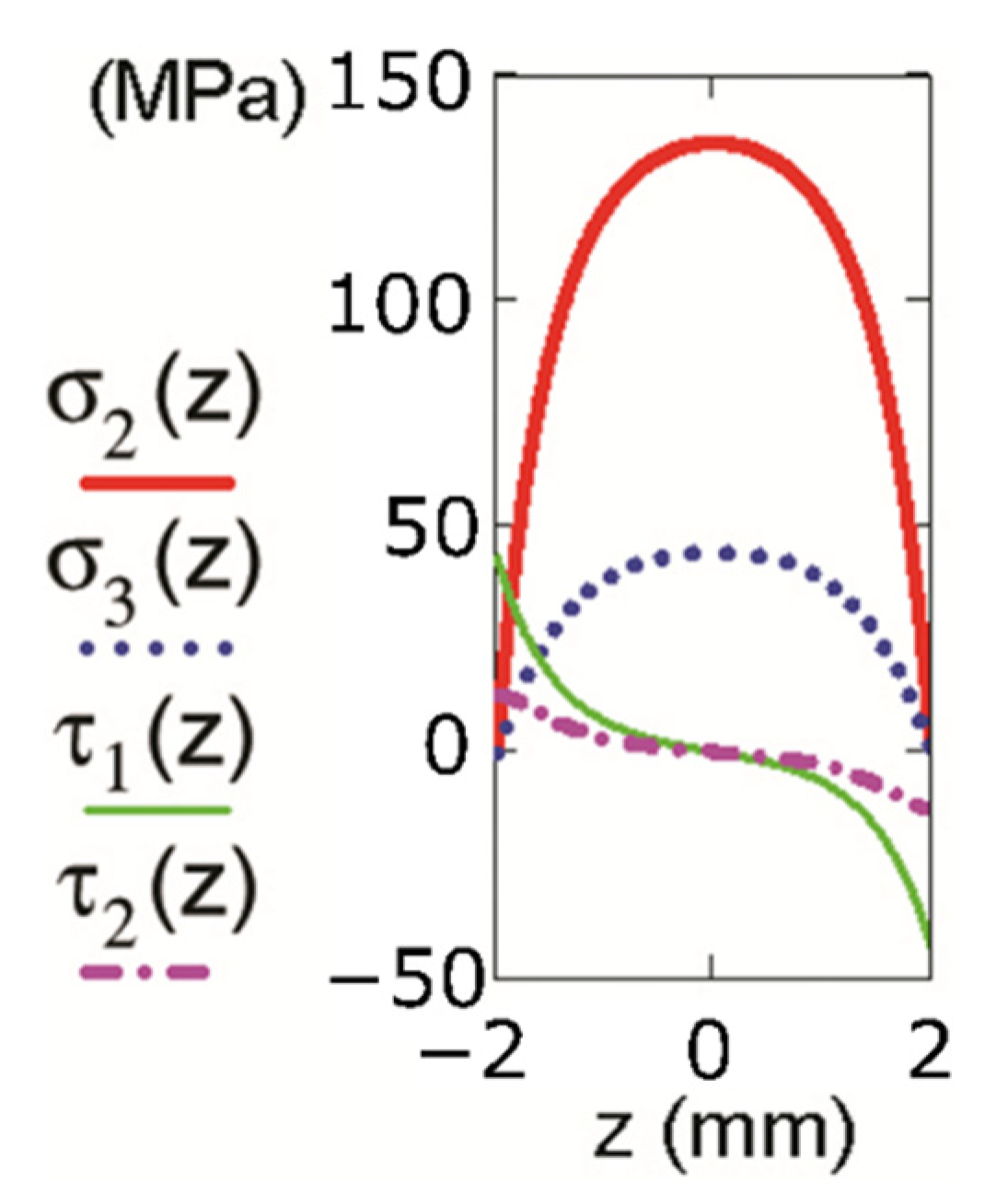
3.2. Determination of Normal and Shear Stresses in the Substrate-Coating System

The distribution of normal and shear stresses in a coated specimen before cracking and after fragmentation with a segment length of 4 mm (Figure 2) according to Equations (1)–(9) is shown in Figure 3 and Figure 4, respectively.
Normal and shear stress distribution analysis in a two-layer coating shows that the maximum normal stresses σ2 and σ3 occur in the central part of the coating. Normal stresses in the top ceramic layer results in cracks in the coating. The authors should also note that the maximum shear stresses of the substrate-bond coat occur at the substrate-bond coat interface τ1 and bond coat-top coat interface τ2 near the free edge of the coating. These τ2 maximum shear stresses lead to delamination of the top ceramic coat. A concentration of shear stresses occurs in the vicinity of the free edge of the coating. With increasing distance from the free edge of the coating, the stress singularity reduces. The maximum shear stresses cause edge detachment of the top layer of the coating because of shear strains in the interface between the top ceramic coat and the metal bond coat. In addition, the decreased length of the cracking coating fragments led to an increased magnitude of the shear stresses.

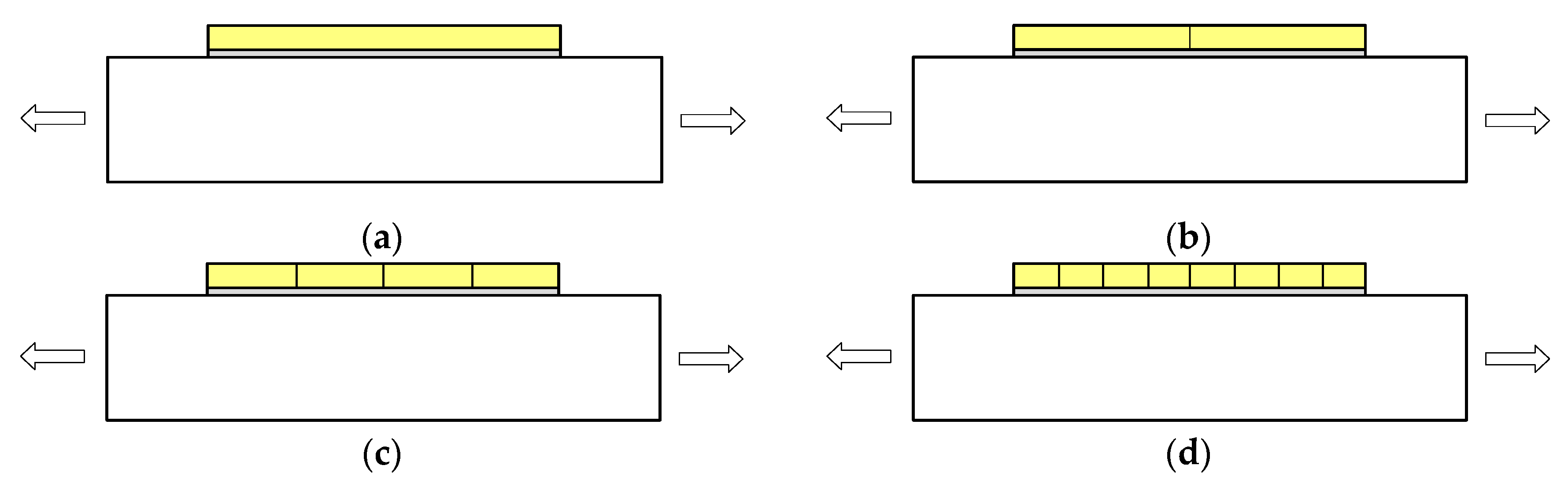
4. Discussion and Review

Coating failure mechanisms vary by environmental factors. They can be adhesion failure, delamination, peeling, flaking, cracking, spalling, blistering, wrinkling, cathodic damage, impact damage, and puncturing [53]. The author described mechanisms for urethane top coat delamination from the epoxy intermediate coating. The explanations include an epoxy tank coating blistering and delamination of an inorganic zinc-containing primer of a three-layer system consisting of a primer, a polyamide-epoxy middle layer, and a urethane top coat. Other authors subjected some of the typical epoxy coatings to the hydrostatic pressure of 35 atmospheres to simulate failure mechanisms in the deep ocean [54]. Modern, flexible electronic devices fail due to tensile forces acting on organic-inorganic multilayer permeation barriers [55]. The damage of two-layer epoxy coatings by curing under thermo-oxidative conditions was explored to provide an approach for corrosion protection on the inner walls of heat exchangers [56]. Stress transfer at the coating-substrate interface and geometric conditions control normal cracking in coating segments and their delamination [42]. Tensile forces initiate fragmentation of laser cladding WC/Ni composite coatings [57].
The authors proposed the fracture mechanism of ceramic coating and aluminum alloy substrate after comparing different thicknesses of ceramic coatings from plasma electrolytic oxidation [58]. They have concluded that the thicker coating more easily leads to faster cracking. This effect is due to the more significant stress concentration. The initiated cracks propagate in the aluminum alloy rather than in the coating-substrate interface. They also found that the ceramic coating adheres to the aluminum alloy substrate significantly better than other tested coatings.
Another failure mode is the occurrence of secondary cracks perpendicular to the main cracks. Cross-linked cracks form parallel to the tensile direction after forming the main cracks perpendicular to the loading direction [59]. The authors assumed that these cross-linked cracks form due to the coating and substrate’s different Poisson behavior [60].
Stress measurement on various cracked segments of a brittle diamond coating has shown that tensile stress generates in the center of the segment under applied tensile load. In contrast, compressive stress generates near the segment edges, and cracking leads to stress relaxation in the coating [61]. In addition, the process requires a higher strain to initiate smaller segment cracking than a larger one.
Four different damage mechanisms are revealed between the substrate and the bond coat: delamination of the adhesion promoter layer, buckling of the entire coating system, vertical cracking, and Kirkendall porosity at the interfaces between the substrate, bond coat, and top coat [62].
According to the estimates of normal and shear stresses (Equations (1)–(9)) calculated by the proposed analytical model, the fracture mechanisms of the two-layer coating can be described as follows. After tensile tests on coated specimens, the following mechanism of destruction of the two-layer coatings was found, as shown in Figure 5a–e. As the specimen is stretched further (Figure 5a), a crack first appears in the outer ceramic coating at a sufficient distance from the free edge of the coating (Figure 5b). Analysis of the distribution of normal stresses in the σ3 ceramic coating shows that the magnitude of these stresses does not change at 3 mm from the free edge of the coating (Figure 3). Therefore, throughout the area where the σ3 maximum normal stresses occur. The probability of an initial crack in the ceramic coating is almost the same. Continuous specimen stretching leads to the forming of a crack network in the ceramic coating (Figure 5c). As the sample is stretched, the length of the coating fragments decreases until it reaches a critical value (Figure 5d). Then the process of detachment of the coating fragments begins (Figure 5e). After the detachment of the top ceramic coat, cracks appear in the metal sub-coating, which has been observed previously [63]. The crack penetrates the metal sub-coating when the outer coating has a higher bond strength. In this case, spalling of the outer coating does not occur, as shown in Figure 5b.
The proposed approach makes it possible to evaluate the cohesive strength of each layer of the two-layer coating and its adhesion strength. In addition, engineers could use the created model and methodology to assess the behavior of other multilayer hard coatings, such as thermosetting materials on steel surfaces [64], which is a current problem for cargo tanks of chemical tankers.
The detachment of intermediate layers and the detachment of the thermosetting hard coating from the steel surface are also a current problem for the cargo tanks of chemical tankers. The problematic effects relate to stress by bending the ship on the shafts and during the cargo operation. These stresses cause the cracking of the hard protective coating of the cargo tank. The steel plate thickness of the tank wall is usually 8–12 mm [65], and the total dry film thickness (DFT) for 2–3 coatings is between 0.3 and 0.6 mm. So, the ratio of steel plate thickness to coating DFT is relatively high (15–35), which aggravates the problem of bending stress. The formation and extension of the cracks in eventually leads to full specimen rupture under applied high-tension forces [66] or too many tensioning cycles.
Aggressive and corrosive charges such as acids penetrate even through tiny cracks and can lead to complete failure of the protective coating.

5. Conclusions

The tensioned substrate, the metal bond coat, and the ceramic top coat exhibit the modulus of elasticity of 196, 142, and 47 GPa, respectively.
Thus, the authors of the present article analyzed the stress state of a metal specimen to which a two-layer plasmas-prayed coating was applied. Experimental studies on samples with two-layer coatings show that fragmentation occurs in the ceramic top layer when the metal substrate is tensioned. The ceramic coating detaches at the critical length of these fragments.
The stress state in the sample with a two-layer coating calculated by the analytical method shows that the maximum normal stresses occur in the 200 μm thick upper ceramic layer at 3 mm from the free edge of the coating.
The performed studies on the destruction processes of two-layer plasma-sprayed coatings are necessary for developing modern knowledge on the characteristics of the performance of coatings under various extreme operating conditions, including an aggressive environment. For example, engineers could apply the proposed methodology and mathematical analysis to study the causes of cracks and delamination between layers. In the future, it is planned to study the influence of the adhesion strength of layers on the mechanism of destruction of two-layer coatings.

Author Contributions

Conceptualization, N.D. and L.V.; Methodology, N.D.; Software, O.M.; Validation, N.D., O.M. and K.C.; formal analysis, O.M.; investigation, O.M.; resources, N.D.; data maintenance, K.C.; writing-creating the original design, N.D.; writing-reviewing and editing, J.B. (Janis Baronins), L.Z., and S.G.; visualization, J.B. (Janis Baronins); supervision, J.B. (Janis Brunavs); project administration, K.C.; funding procurement, K.C. All authors have read and agreed to the published version of the manuscript.

Funding

This research was funded by the Latvian Science Council. Project “Development of Smart Technologies for Efficient and Reliable Waterborne Operations” (STEEWO, No. LZP-2019/1-0478).

Institutional Review Board Statement

Not applicable.

Informed Consent Statement

Not applicable.

Data Availability Statement

Not applicable.

Conflicts of Interest

The authors declare that there is no conflict of interest.

References

  1. Bala, N.; Singh, H.; Prakash, S. Accelerated Hot Corrosion Studies of Cold Spray Ni–50Cr Coating on Boiler Steels. Mater. Des. 2010, 31, 244–253. [Google Scholar] [CrossRef]
  2. Priyantha, N.; Jayaweera, P.; Sanjurjo, A.; Lau, K.; Lu, F.; Krist, K. Corrosion-Resistant Metallic Coatings for Applications in Highly Aggressive Environments. Surf. Coat. Technol. 2003, 163–164, 31–36. [Google Scholar] [CrossRef]
  3. Sidky, P.S.; Hocking, M.G. Review of Inorganic Coatings and Coating Processes for Reducing Wear and Corrosion. Br. Corros. J. 1999, 34, 171–183. [Google Scholar] [CrossRef]
  4. Clarke, D.R.; Oechsner, M.; Padture, N.P. Thermal-Barrier Coatings for More Efficient Gas-Turbine Engines. MRS Bull. 2012, 37, 891–898. [Google Scholar] [CrossRef]
  5. Balaji, M.; Murthy, B.S.N.; Rao, N.M. Optimization of Cutting Parameters in Drilling of AISI 304 Stainless Steel Using Taguchi and ANOVA. Procedia Technol. 2016, 25, 1106–1113. [Google Scholar] [CrossRef]
  6. Irtiseva, K.; Lapkovskis, V.; Mironovs, V.; Ozolins, J.; Thakur, V.K.; Goel, G.; Baronins, J.; Shishkin, A. Towards Next-Generation Sustainable Composites Made of Recycled Rubber, Cenospheres, and Biobinder. Polymers 2021, 13, 574. [Google Scholar] [CrossRef] [PubMed]
  7. Li, H.; Cui, C.; Cai, J.; Zhang, M.; Sheng, Y. Utilization of Steel Slag in Road Semi-Rigid Base: A Review. Coatings 2022, 12, 994. [Google Scholar] [CrossRef]
  8. Goncalves Dos Santos, A.; Montes-Ruiz Cabello, F.J.; Vereda, F.; Cabrerizo-Vilchez, M.A.; Rodriguez-Valverde, M.A. Oscillating Magnetic Drop: How to Grade Water-Repellent Surfaces. Coatings 2019, 9, 270. [Google Scholar] [CrossRef]
  9. Shishkin, A.; Drozdova, M.; Kozlov, V.; Hussainova, I.; Lehmhus, D. Vibration-Assisted Sputter Coating of Cenospheres: A New Approach for Realizing Cu-Based Metal Matrix Syntactic Foams. Metals 2017, 7, 16. [Google Scholar] [CrossRef]
  10. Shishkin, A.; Hussainova, I.; Kozlov, V.; Lisnanskis, M.; Leroy, P.; Lehmhus, D. Metal-Coated Cenospheres Obtained via Magnetron Sputter Coating: A New Precursor for Syntactic Foams. JOM 2018, 70, 1319–1325. [Google Scholar] [CrossRef]
  11. Kumari, S.; Islam, A.; Mirche, K.K.; Kiran, P.S.; Maurya, S.S.; Kumar, D.; Pandey, S.M.; Keshri, A.K. Plasma Sprayed Graphene Reinforced Titanium Nitride Composite Coating: An Effective Solution for Mitigating the Corrosion Attack. Surf. Coat. Technol. 2022, 445, 128704. [Google Scholar] [CrossRef]
  12. Wang, P.; Ma, G.; Su, F.; Guo, W.; Chen, S.; Zhao, H.; Liu, M.; Wang, H. Excellent Mechanical, Electrical and Current-Carrying Tribological Properties of Nano/Micro Composite TiO2−x Coating Prepared by Supersonic Plasma Spraying. Surf. Coat. Technol. 2022, 445, 128710. [Google Scholar] [CrossRef]
  13. Sathish, S.; Geetha, M.; Aruna, S.T.; Balaji, N.; Rajam, K.S.; Asokamani, R. Studies on Plasma Sprayed Bi-Layered Ceramic Coating on Bio-Medical Ti–13Nb–13Zr Alloy. Ceram. Int. 2011, 37, 1333–1339. [Google Scholar] [CrossRef]
  14. Schlichting, K.W.; Padture, N.P.; Klemens, P.G. Thermal Conductivity of Dense and Porous Yttria-Stabilized Zirconia. J. Mater. Sci. 2001, 36, 3003–3010. [Google Scholar] [CrossRef]
  15. Golosnoy, I.O.; Cipitria, A.; Clyne, T.W. Heat Transfer Through Plasma-Sprayed Thermal Barrier Coatings in Gas Turbines: A Review of Recent Work. J. Therm. Spray Technol. 2009, 18, 809–821. [Google Scholar] [CrossRef]
  16. Wang, Y.; Sayre, G. Commercial Thermal Barrier Coatings with a Double-Layer Bond Coat on Turbine Vanes and the Process Repeatability. Surf. Coat. Technol. 2009, 203, 2186–2192. [Google Scholar] [CrossRef]
  17. TAKAHASHI, S.; HARADA, Y. In Situ Observation of Creep and Fatigue Failure Behavior for Plasma-Sprayed Thermal Barrier Coating Systems. J. Solid Mech. Mater. Eng. 2010, 4, 235–243. [Google Scholar] [CrossRef]
  18. Antonov, M.; Afshari, H.; Baronins, J.; Adoberg, E.; Raadik, T.; Hussainova, I. The Effect of Temperature and Sliding Speed on Friction and Wear of Si3N4, Al2O3, and ZrO2 Balls Tested against AlCrN PVD Coating. Tribol. Int. 2018, 118, 500–514. [Google Scholar] [CrossRef]
  19. Somiya, S.; Aldinger, F.; Spriggs, R.M.; Uchino, K.; Koumoto, K.; Kaneno, M. Handbook of Advanced Ceramics: Materials, Applications, Processing, and Properties. In Handbook of Advanced Ceramics; Elsevier Science & Technology Books: Amsterdam, The Netherlands, 2003; ISBN 9780126546408. [Google Scholar]
  20. Ashby, M.F. Materials Selection in Mechanical Design, 4th ed.; Butterworth Heinemann: Oxford, Germany, 2010; ISBN 978-1-85617-663-7. [Google Scholar]
  21. Yasuda, I.; Hishinuma, M. Lattice Expansion of Acceptor-Doped Lanthanum Chromites under High-Temperature Reducin’g Atmospheres. Electrochemistry 2000, 68, 526–530. [Google Scholar] [CrossRef]
  22. Hayashi, H.; Saitou, T.; Maruyama, N.; Inaba, H.; Kawamura, K.; Mori, M. Thermal Expansion Coefficient of Yttria Stabilized Zirconia for Various Yttria Contents. Solid State Ion. 2005, 176, 613–619. [Google Scholar] [CrossRef]
  23. Baronins, J.; Antonov, M.; Bereznev, S.; Raadik, T.; Hussainova, I. Raman Spectroscopy of Multilayered AlCrN Coating under High Temperature Sliding/Oxidation. Key Eng. Mater. 2019, 799, 9–14. [Google Scholar] [CrossRef]
  24. Schulz, U.; Leyens, C.; Fritscher, K.; Peters, M.; Saruhan-Brings, B.; Lavigne, O.; Dorvaux, J.-M.; Poulain, M.; Mévrel, R.; Caliez, M. Some Recent Trends in Research and Technology of Advanced Thermal Barrier Coatings. Aerosp. Sci. Technol. 2003, 7, 73–80. [Google Scholar] [CrossRef]
  25. Galetz, C.M. Superalloys; Aliofkhazraei, M., Ed.; InTech: London, UK, 2015; ISBN 978-953-51-2212-8. [Google Scholar]
  26. Pereira Falcón, J.C.; Echeverría, A.; Afonso, C.R.M.; Zambrano Carrullo, J.C.; Amigó Borrás, V. Microstructure Assessment at High Temperature in NiCoCrAlY Overlay Coating Obtained by Laser Metal Deposition. J. Mater. Res. Technol. 2019, 8, 1761–1772. [Google Scholar] [CrossRef]
  27. Pomeroy, M.J. Coatings for Gas Turbine Materials and Long Term Stability Issues. Mater. Des. 2005, 26, 223–231. [Google Scholar] [CrossRef]
  28. Kim, D.; Shin, I.; Koo, J.; Kim, S.; Seo, D.; Kim, J.; Seok, C. Quantitative Analysis on the Depletion Rate of β-NiAl Phases in MCrAlY Coating. J. Mech. Sci. Technol. 2014, 28, 513–519. [Google Scholar] [CrossRef]
  29. Pereira, J.C.; Zambrano, J.C.; Rayón, E.; Yañez, A.; Amigó, V. Mechanical and Microstructural Characterization of MCrAlY Coatings Produced by Laser Cladding: The Influence of the Ni, Co and Al Content. Surf. Coat. Technol. 2018, 338, 22–31. [Google Scholar] [CrossRef]
  30. di Girolamo, G.; Alfano, M.; Pagnotta, L.; Taurino, A.; Zekonyte, J.; Wood, R.J.K. On the Early Stage Isothermal Oxidation of APS CoNiCrAlY Coatings. J. Mater. Eng. Perform. 2012, 21, 1989–1997. [Google Scholar] [CrossRef]
  31. Liu, H.; Chen, P.; Yang, H.; Hao, J.; Tian, X.; He, X.; Yu, G. Processing Window and Microstructure of NiCoCrAlY Coating Deposited on Cast Iron Using Multilayer Laser Cladding. J. Spectrosc. 2019, 2019, 9308294. [Google Scholar] [CrossRef]
  32. Tancret, F.; Bhadeshia, H.K.D.H.; MacKay, D.J.C. Design of a Creep Resistant Nickel Base Superalloy for Power Plant Applications: Part 1–Mechanical Properties Modelling. Mater. Sci. Technol. 2003, 19, 283–290. [Google Scholar] [CrossRef]
  33. Bawa, S.; Ahmed, A.; Okonkwo, P. Alumina Phase Transformation from Thermal Decomposition of Ammonium Alum Synthesized from Kankara Kaolin. Niger. J. Technol. 2017, 36, 822–828. [Google Scholar] [CrossRef]
  34. Marginean, G.; Utu, D. Cyclic Oxidation Behaviour of Different Treated CoNiCrAlY Coatings. Appl. Surf. Sci. 2012, 258, 8307–8311. [Google Scholar] [CrossRef]
  35. Nijdam, T.J.; Kwakernaak, C.; Sloof, W.G. The Effects of Alloy Microstructure Refinement on the Short-Term Thermal Oxidation of NiCoCrAlY Alloys. Metall. Mater. Trans. A 2006, 37, 683–693. [Google Scholar] [CrossRef]
  36. Thiem, P.G.; Chornyi, A.; Smirnov, I.V.; Krüger, M. Comparison of Microstructure and Adhesion Strength of Plasma, Flame and High Velocity Oxy-Fuel Sprayed Coatings from an Iron Aluminide Powder. Surf. Coat. Technol. 2017, 324, 498–508. [Google Scholar] [CrossRef]
  37. Bose, S.; DeMasi-Marcin, J. Thermal Barrier Coating Experience in Gas Turbine Engines at Pratt & Whitney. J. Therm. Spray Technol. 1997, 6, 99–104. [Google Scholar] [CrossRef]
  38. Antonov, M.; Hussainova, I.; Sergejev, F.; Kulu, P.; Gregor, A. Assessment of Gradient and Nanogradient PVD Coatings Behaviour under Erosive, Abrasive and Impact Wear Conditions. Wear 2009, 267, 898–906. [Google Scholar] [CrossRef]
  39. Baronins, J.; Podgursky, V.; Antonov, M.; Bereznev, S.; Hussainova, I. Electrochemical Behaviour of TiCN and TiAlN Gradient Coatings Prepared by Lateral Rotating Cathode Arc PVD Technology. Key Eng. Mater. 2016, 721, 414–418. [Google Scholar] [CrossRef]
  40. Surzhenkov, A.; Baroninš, J.; Viljus, M.; Traksmaa, R.; Kulu, P. Sliding Wear of Composite Stainless Steel Hardfacing under Room and Elevated Temperature; Trans Tech Pub.: Kaunas, Lithuania, 2017; Volume 267, ISBN 9783035711479. [Google Scholar]
  41. Meghwal, A.; Singh, S.; Anupam, A.; King, H.J.; Schulz, C.; Hall, C.; Munroe, P.; Berndt, C.C.; Ang, A.S.M. Nano- and micro-mechanical properties and corrosion performance of a HVOF sprayed AlCoCrFeNi high-entropy alloy coating. J. Alloys Compd. 2022, 912, 165000. [Google Scholar] [CrossRef]
  42. ur Rehman, H.; Ahmed, F.; Schmid, C.; Schaufler, J.; Durst, K. Study on the Deformation Mechanics of Hard Brittle Coatings on Ductile Substrates Using In-Situ Tensile Testing and Cohesive Zone FEM Modeling. Surf. Coat. Technol. 2012, 207, 163–169. [Google Scholar] [CrossRef]
  43. Dolgov, N.A.; Smirnov, I.V.; Besov, A.V. Studying the Elastic Properties and Adhesive Strength of Plasma-Sprayed Double-Layer Coatings During Tensile Tests. Powder Metall. Met. Ceram. 2015, 54, 40–46. [Google Scholar] [CrossRef]
  44. Agrawal, D.C.; Raj, R. Measurement of the Ultimate Shear Strength of a Metal-Ceramic Interface. Acta Metall. 1989, 37, 1265–1270. [Google Scholar] [CrossRef]
  45. Dolgov, N.A. Analytical Methods to Determine the Stress State in the Substrate–Coating System Under Mechanical Loads. Strength Mater. 2016, 48, 658–667. [Google Scholar] [CrossRef]
  46. Rizov, V. Analysis of Cylindrical Delamination Cracks in Multilayered Functionally Graded Non-Linear Elastic Circular Shafts under Combined Loads. Frat. Ed Integrità Strutt. 2018, 12, 158–177. [Google Scholar] [CrossRef]
  47. Bulbuk, O.; Velychkovych, A.; Mazurenko, V.; Ropyak, L.; Pryhorovska, T. Analytical Estimation of Tooth Strength, Restored by Direct or Indirect Restorations. Eng. Solid Mech. 2019, 193–204. [Google Scholar] [CrossRef]
  48. Li, L.-A.; Li, R.-J.; Wang, S.-B.; Wang, Z.-Y.; Li, T.; Li, C.-W. Stress Analysis of Film-on-Substrate Structure under Tensile Loads. Mech. Mater. 2018, 120, 1–14. [Google Scholar] [CrossRef]
  49. Leguillon, D.; Li, J.; Martin, E. Multi-Cracking in Brittle Thin Layers and Coatings Using a FFM Model. Eur. J. Mech. A/Solids 2017, 63, 14–21. [Google Scholar] [CrossRef]
  50. Vitkovskii, I.V.; Dolgov, N.A.; Konev, A.N. Stressed State of the Electrical Insulation Barrier in the Wall Structure of a Thermonuclear Reactor Liquid-Metal Blanket. Tech. Phys. 2011, 56, 1508–1512. [Google Scholar] [CrossRef]
  51. Dolgov, N.A. Method for Determining the Modulus of Elasticity for Gas Thermal Spray Coatings. Powder Metall. Met. Ceram. 2004, 43, 423–428. [Google Scholar] [CrossRef]
  52. Dolgov, N.A.; Lyashenko, B.A.; Rushchitskii, Y.Y.; Veremchuk, V.S.; Terletskii, V.A.; Kovalenko, A.P. Effects of Elasticity Differences between Substrate and Coating on the State of Stress and Strain in a Composite. Part 2. Coating Tensile Stress Distribution. Strength Mater. 1996, 28, 373–375. [Google Scholar] [CrossRef]
  53. Weldon, D.G. Failure Analysis of Paints and Coatings, Revised Edition; Revised ed.; John Wiley & Sons, Ltd.: Chichester, UK, 2009; ISBN 9780470744673. [Google Scholar]
  54. Liu, Y.; Wang, J.; Liu, L.; Li, Y.; Wang, F. Study of the Failure Mechanism of an Epoxy Coating System under High Hydrostatic Pressure. Corros. Sci. 2013, 74, 59–70. [Google Scholar] [CrossRef]
  55. Jia, Z.; Tucker, M.B.; Li, T. Failure Mechanics of Organic–Inorganic Multilayer Permeation Barriers in Flexible Electronics. Compos. Sci. Technol. 2011, 71, 365–372. [Google Scholar] [CrossRef]
  56. Cozzarini, L.; Marsich, L.; Ferluga, A.; Schmid, C. Failure Investigation of a Protective Epoxy Coating by Means of Crosscheck between Infrared Spectroscopy and Thermal Analysis. Eng. Fail. Anal. 2020, 107, 104201. [Google Scholar] [CrossRef]
  57. Xu, J.-S.; Zhang, X.-C.; Xuan, F.-Z.; Tian, F.-Q.; Wang, Z.-D.; Tu, S.-T. Tensile Properties and Fracture Behavior of Laser Cladded WC/Ni Composite Coatings with Different Contents of WC Particle Studied by in-Situ Tensile Testing. Mater. Sci. Eng. A 2013, 560, 744–751. [Google Scholar] [CrossRef]
  58. Zou, Y.; Wang, Y.; Wei, D.; Du, Q.; Ouyang, J.; Jia, D.; Zhou, Y. In-Situ SEM Analysis of Brittle Plasma Electrolytic Oxidation Coating Bonded to Plastic Aluminum Substrate: Microstructure and Fracture Behaviors. Mater. Charact. 2019, 156, 109851. [Google Scholar] [CrossRef]
  59. Liu, Y.; Fu, S.; Wang, Z.; Yan, X.; Xi, N.; Wu, Y.; Chen, H. Tensile Properties, Shear Strength Calculation and Cracking Behavior of Bulk Composite Comprised of Thick HVOF Sprayed Coating and Steel Substrate. Surf. Coat. Technol. 2019, 374, 807–814. [Google Scholar] [CrossRef]
  60. Dolgov, N.A.; Lyashenko, B.A.; Rushchitskii, Y.Y.; Veremchuk, V.S.; Terletskii, V.A.; Kovalenko, A.P. Effects of Differences in Elastic Characteristics between Substrate and Coating on the Stress and Strain State in a Composite. 1. Estimating Tensile Stresses in the Coating. Strength Mater. 1995, 27, 525–530. [Google Scholar] [CrossRef]
  61. Ahmed, F.; Bayerlein, K.; Rosiwal, S.M.; Göken, M.; Durst, K. Stress Evolution and Cracking of Crystalline Diamond Thin Films on Ductile Titanium Substrate: Analysis by Micro-Raman Spectroscopy and Analytical Modelling. Acta Mater. 2011, 59, 5422–5433. [Google Scholar] [CrossRef]
  62. Fiedler, T.; Groß, R.; Rösler, J.; Bäker, M. Damage Mechanisms of Metallic HVOF-Coatings for High Heat Flux Application. Surf. Coat. Technol. 2017, 316, 219–225. [Google Scholar] [CrossRef]
  63. Dikova, T.; Vasilev, T.; Dolgov, N. Failure of Ceramic Coatings on Cast and Selective Laser Melted Co-Cr Dental Alloys under Tensile Test: Experiment and Finite Element Analysis. Eng. Fail. Anal. 2019, 105, 1045–1054. [Google Scholar] [CrossRef]
  64. Matykiewicz, D.; Skórczewska, K. Characteristics and Application of Eugenol in the Production of Epoxy and Thermosetting Resin Composites: A Review. Materials 2022, 15, 4824. [Google Scholar] [CrossRef]
  65. Zeybek, Ö. The Stability of Anchored Cylindrical Steel Tanks with a Secondary Stiffening Ring. Int. J. Press. Vessel. Pip. 2022, 198, 104661. [Google Scholar] [CrossRef]
  66. Yang, D.; Liu, J.; Zhang, J.; Liang, X.; Zhang, X. In Situ High-Temperature Tensile Fracture Mechanism of PS-PVD EBCs. Coatings 2022, 12, 655. [Google Scholar] [CrossRef]
Figure 1. Schematic illustration of a coated specimen illustrated on YZ axis: 1—substrate; 2—bond coat (adhesion layer); 3—top ceramic coating. Designations: h1, h2, h3—thicknesses; l—the distance from the edge to the center of the coat.
Coatings 12 01175 g001
Figure 2. Specimen with two-layer coating after tensile test, the cracks marked by vertical arrows in the uppermost ceramic layer (a); and side view of delaminated coating marked: 1, substrate; 2, metal bond coat; 3, top ceramic coat with attached strain gauge (b).
Coatings 12 01175 g002
Figure 3. Distribution of normal and shear stresses before cracking in the ceramic surface layer (ceramic hard surface layer).
Coatings 12 01175 g003
Figure 4. Distribution of normal and shear stresses after fragmentation of the coating (the length of the coating segment is 4 mm).
Coatings 12 01175 g004
Figure 5. Schematic representation of the cracking and delamination behavior of the ceramic surface layer in the tensile test. The stress of the substrate occurs under the applied load (a); the hard coating cracks (b) and fragmentation occurs (c,d) the delamination of the hard coating detaches from the adhesion layer (e).
Coatings 12 01175 g005aCoatings 12 01175 g005b
Table 1. Main properties of yttria-stabilized zirconia.
PropertiesValue
Hardness at 20 °C (need in K), GPa10.5 [18]
Fracture toughness KIC, MPa m0.56 [18]
Young’s modulus of elasticity, GPa210 [18]
Poisson’s ratio0.32 [19]
Thermal conductivity at 20 °C, W m−1 K−13 [14]
Maximum operating temperature, °C1200 [20]
Density, kg m−36000
Thermal diffusivity, ×10−6 m2 s−10.9 [18]
Coefficient of thermal expansion K−1 (between 298 and 1273 K)10.8 × 10⁻⁶ (3 mol Y)
0.5 × 10⁻⁶ (8 mol Y) [21,22]
Table 2. Main properties of NiCoCrAlY.
PropertiesValue
Hardness at 20 °C, GPa6.2 [29]
Young’s modulus of elasticity, GPa150–200 (as sprayed)
200–325 (oxidized) [30]
Thermal conductivity at 20 °C, W·m−1·K−14.3 [31]
Melting temperature, °C1330 [31]
Density, kg·m−37320 [31]
Coefficient of thermal expansion, K−1 (between 298 and 1273 K)1.4 × 10⁻⁵ [31]
Table 3. Applied plasma spray processes for NiCoCrAlY bond coat and ZrO2-8%Y2O3 top coat on 08Kh18N10 stainless steel.
Applied Powder (Feedstock)NiCoCrAlY
(Bond Coat)
ZrO2-8%Y2O3
(Top Coat)
Argon flow rate, L·min−14040
Hydrogen flow rate, L·min−11010
Arc current, A250290
Voltage, V6080
Spray distance from nozzle, mm140130
Publisher’s Note: MDPI stays neutral with regard to jurisdictional claims in published maps and institutional affiliations.

