Article

Erosive Wear Behavior of High-Chromium Cast Iron: Combined Effect of Erodent Powders and Destabilization Heat Treatments

1
Department of Engineering, University of Ferrara, 44122 Ferrara, Italy
2
Department of Physics and Earth Science, University of Ferrara, 44122 Ferrara, Italy
*
Author to whom correspondence should be addressed.
Coatings 2022, 12(8), 1218; https://doi.org/10.3390/coatings12081218
Submission received: 2 July 2022 / Revised: 16 August 2022 / Accepted: 17 August 2022 / Published: 20 August 2022
(This article belongs to the Section Tribology)

Abstract

:
High-chromium cast irons are frequently used in high-demanding applications, where low production costs and wear performance are key factors. The excellent abrasive resistance of these alloys results from the overall microstructural features, i.e., type, morphology, and distribution of hard primary and secondary carbides, along with the matrix constituents. Such a microstructure is the result of the chemical composition and solidification process, even though it could be further tuned by heat treatments. These latter are usually performed to destabilize the austenite and to induce the precipitation of secondary carbides. The present study investigates the combined effect of destabilization heat treatment route and erodent powder type on the erosive wear behavior of two commercial hypereutectic white cast irons. The as-received and the heat-treated materials were analyzed through optical and scanning electron microscopy, hardness tests, and X-ray diffraction to determine the relationship between microstructural variations and applied heat treatment. The erosive resistance was evaluated per the ASTM G76 standard in a purpose-built air blast test rig. Experiments were performed considering a raw meal powder, commonly used in cement factories, and Al2O3 as erodent powders. The adopted heat treatments were effective in increasing the overall hardness of the material, but this was not directly related to the erosion resistance. By contrast, the relative hardness ratio, i.e., erodent/target hardness, affects the erosion rate and different behaviors in relation to the softer/harder erodent particles were found.

1. Introduction

High chromium cast irons (HCCIs) are broadly employed in severe abrasive wear conditions, such as mining and drilling applications, foundry, metallurgy, ceramic and processing aggregate industries, soil preparation equipment, chute liner, thermal power industries, and others [1]. In such applications, unforeseen failures and, in turn, economic losses are frequently related to wear damages. Hence, there is a continuing need for materials with excellent abrasion wear and corrosion resistance as well as good heavy load transfer application behavior.
HCCIs are a group of materials characterized by excellent resistance to abrasive wear, which stems from their peculiar chemical composition that can be relatively wide, 2–4 wt.% of carbon and 15–30 wt.% of chromium [1]. HCCIs may be regarded as composite materials since they show a structure consisting of M7C3 (M = Cr, Fe) carbides, with a Vickers hardness of 1300 to 1800, in a softer iron matrix [2]. According to the phase diagram, hyper-eutectic alloys comprise primary M7C3 carbides surrounded by a matrix of eutectic carbides and austenite. The growth characteristics of M7C3 carbides have been widely investigated in the literature: they have an irregular polygonal shape with several hollows in the center and gaps on the edge [3,4,5].
Several researches have demonstrated the strong relation between microstructure and abrasion resistance, highlighting the role of the morphology, size and distribution of the hard phases in affecting the resistance of the alloy [6,7,8,9,10,11]. Although extensive research has been carried out on both the abrasion resistance of HCCIs and on the solid particle erosion phenomena [12,13], few studies have dealt with the ASTM G76 standard reference, taking into account the difficult mechanical-microstructural relationships that rule the erosion resistance [14,15,16,17,18,19,20,21,22] of such alloys. Besides, the modification of the morphology, size, and distribution of carbides via the addition of alloying elements has been proved as an effective way to enhance the wear resistance of HCCIs [23,24,25,26]. In addition to the M7C3-type carbides, Fe-Cr-C alloys usually include strong carbide forming elements, such as Nb, V, W, and Ti, that induce the formation of MC-type carbides, harder and finer than Cr-based carbides. Nevertheless, the use of these expensive alloying elements, effective in enhancing wear resistance [27,28,29], is limited in industrial applications for cost reasons.
The microstructural and mechanical properties of the as-cast HCCIs can also be improved by applying specific heat treatments, namely destabilization (or critical) and subcritical heat treatments. Destabilization is performed by heating at 800–1100 °C for 1–6 h [30,31,32,33,34,35] to destabilize the highly alloyed austenitic matrix, promoting its transformation into martensite upon cooling and the precipitation of secondary carbides within the matrix [35,36,37]. Besides, subcritical heat treatments are conducted after destabilization by heating at 200–600 °C for 2–6 h to further increase the precipitation of secondary carbides and remove the retained austenite that remained after destabilization [32,34,35]. Previous research has established the effects of heat treatment routes on carbide precipitation [30,38], erosive wear resistance [39,40,41] and fracture toughness [42] of HCCIs. To date, most of the studies have systematically evaluated and assessed the characteristics of the erodent particles (shape, size, velocity, angle rotation and impact angle) that affect surface erosion [13]. Despite that, to the authors’ knowledge, the combined effects of erodent type and heat treatment has not yet been examined.
Within this context, the present study addresses the microstructural features and the erosive wear behavior of two HCCIs, both in the as-received condition (AR) and after three different heat treatment (TT) routes, tested with two erodent powders. The paper begins with a synopsis of the literature on HCCIs, describing the destabilization heat treatments and the microstructural and mechanical factors affecting the wear behavior. Section 2 outlines the adopted experimental methods to assess the microstructural and erosive wear resistance, together with the description of the performed heat treatment routes. Section 3 presents the experimental findings in terms of microstructural characterization of the alloys in the as-received and heat-treated conditions, hardness values, X-ray diffraction analyses and erosion behavior. Lastly, Section 4 contains the discussion of the obtained results by referring to previous studies and focusing on the proposed combined effect of erodent powders and destabilization heat treatments on erosion resistance.
The novelty of the present paper is related to the investigation of the wear-resistant behavior of heat-treated hardfacing alloys, considering the role of the type and dimension of the erodent particles. The powder has a pivotal role, not only because of its chemical composition and dimension but also considering its hardness against that of the tested material.

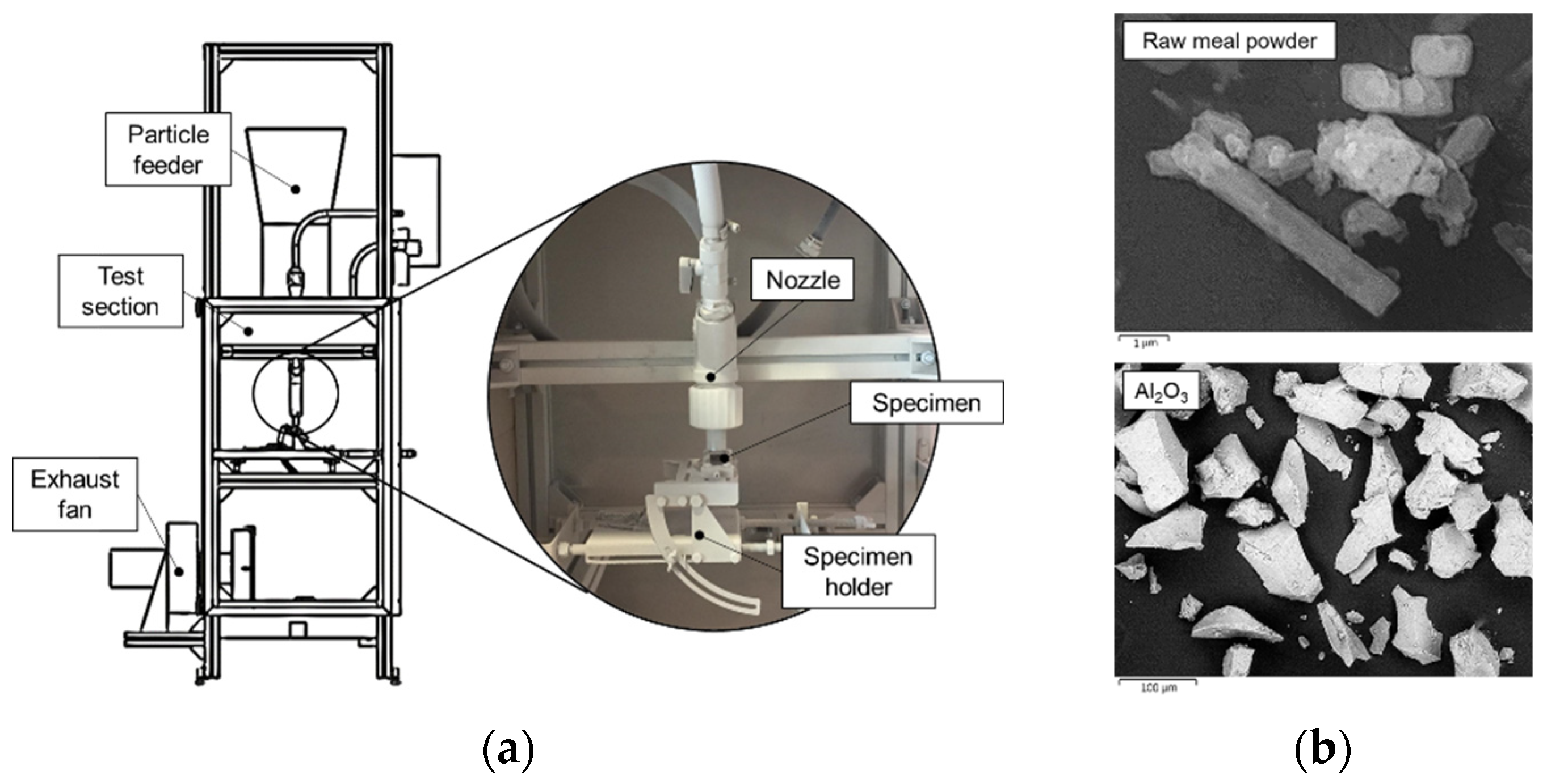
2. Materials and Methods

Two hyper-eutectic HCCIs, designated as Alloy 1 and Alloy 2, were considered in the present investigation. The samples were cut from commercially available wear plates made by the open-arc welding of a flux-cored wire. The HCCI hardfacing electrodes were deposited on low carbon steel plates whose nominal thickness, as well as of the hardfacing, was 5 mm. The chemical composition of the alloys was determined through the Glow Discharge Optical Emission Spectrometry (GD-OES, Spectruma Analitik GDS 650, Hof, Germany) technique, and it is reported in Table 1. Both the alloys have a chromium content of about 20 wt.% that improves the wear resistance, and about 4 wt.% of niobium that is a generator of hard carbides (up to 1900 HV) that promotes gains of wear resistance [23,43]. Alloy 1 also has molybdenum, tungsten, and vanadium, which are generators of hard carbides too [2,24].
The specimens, 20 mm × 20 mm × 10 mm, were cut by the abrasive water-jet process from the original wear plates. The top surface of the wear plates was characterized by the so-called bead pattern, i.e., juxtaposed passes with continuous overlap, that enables to counteract severe wear conditions. Moreover, stress relief cracks, resulting from the relaxation of heat stress in the deposit, developing at right angles to the weld beads and regularly spaced were observed. For more details the reader should refer to [22,44].
To study the combined effect of erodent powders and destabilization heat treatments on the erosive wear behavior of the HCCIs, the investigation comprised: (i) heat treatment of the specimens, (ii) microstructural characterization, hardness tests and X-ray diffraction (XRD) analyses, and (iii) erosive wear tests. Hence, for each of the hereafter heat treatment conditions, two specimens were prepared, one for the metallographic and hardness analyses and one for the erosive wear tests.
The influence of temperature, time and type of cooling media were evaluated by considering for both Alloy 1 and Alloy 2, three different heat treatment routes derived from the literature and detailed in the following Table 2.
The first one, named HT1, has been investigated by Gonzalez-Pociño et al. [41] to test the erosive wear resistance of a white cast iron measured by compressed air blasting with corundum particles and applying a pressure of 4 bar, a flow rate of 160 g/min and a 30° impact angle. The authors compared the cooling media (air or oil) and different dwell times for a fixed dwelling temperature of 1000 °C. The obtained results illustrated the efficacy of this treatment in destabilizing the austenite and promoting a great amount of precipitated secondary carbides. More specifically, for the oil quenched samples, a maximum in the erosive wear resistance was obtained after 8 h of austenite destabilization, which corresponds to the condition of highest percentages of secondary carbides (56.52 ± 1.80). The second one, named HT2, has been proved to be good for the higher overall hardness and wear resistance with respect to the as-cast high-chromium white irons examined by Bedolla-Jacuinde et al. according to the ASTM G65 standard [45]. For the heat-treated samples, the matrix strengthening by martensite and secondary carbides provides better support against carbide cracking than that offered by the austenitic matrix in the as-cast irons. At last, the third heat treatment, named HT3, has been recently proposed by Agustina Guitar et al. [46] for the increment of the bulk hardness, the secondary carbide average size and fraction of the considered high-chromium cast iron. All the above-described treatments were conducted by an LTF (Lenton Furnaces and Ovens, Hope, UK) tube furnace device.
Metallographic and hardness investigations were performed on both the as-received and heat-treated samples. Bulk hardness measurements were carried out on the ground surfaces (silicon carbide papers up to 1200-grit finish) by a VH Metkon (Metkon Instruments Inc., Bursa, Turkey) Vickers hardness tester under 30 kg test load and 15 s loading time (HV30). The mean Vickers hardness was calculated from five indentations to check the reproducibility of the data. The specimens for metallographic investigations were prepared according to the standard metallographic techniques and finally polished with a diamond suspension of 1 μm. Chemical etching was performed by Kalling’s No. 2 reagent (5 g CuCl2, 100 mL HCl, 100 mL C2H5OH) to reveal the microstructure: the samples were immersed in the reagent for 5 s, rinsed with ethanol, and air-dried. Metallographic investigations were conducted through a Leica DMi8A (Leica, Wetzlar, Germany) optical microscope (OM) and a Zeiss EVO MA 15 (Zeiss, Oberkochen, Germany) scanning electron microscope (SEM), equipped with an Oxford X-Max 50 (Oxford Instruments, Abingdon-on-Thames, UK) energy dispersive microprobe for semi-quantitative analyses (EDS). The SEM micrographs were recorded in secondary electron imaging (SEI-SEM) and back-scattered electron (BSE-SEM) modes. XRD powder patterns were collected on a Bruker D8 (Bruker, Billerica, MA, USA) Advance DaVinci diffractometer equipped with a Cu sealed tube and LYNXEYE XE Si strip detector whose energy resolution prevented any significant contribution of X-ray fluorescence from chromium to add to the background. The optimal counting statistics achievable with the strip detector also allowed recording very weak diffraction lines. Powder diffraction patterns were modeled for quantitative phase analysis by the Rietveld method using the Bruker TOPAS 5.0 program.
As for the erosive wear tests, the specimens were prepared according to the standard metallographic techniques, i.e., ground and polished (mirror-like finishing up to 1 µm diamond paste). Erosion tests were carried out through an on-purpose built test rig inspired by the ASTM G76 standard using two different erodent powders: (i) a raw meal powder commonly used in cement factories (particles’ mean diameter = 4.34 μm) and (ii) Al2O3 powder (particles’ mean diameter = 50.0 ± 5 μm). As for the raw meal powder, Table 3 shows the chemical composition and the hardness of the adopted erodent. The detailed characterization of the erodent particles, i.e., morphology and particle size distribution, can be found in [44].
A sketch of the erosion test rig is shown in Figure 1a. The SEI-SEM images of a powder sample in the as-received condition for both the raw meal powder and the Al2O3 powder are displayed in Figure 1b. The erosion tests were conducted at a constant powder-feeding rate of 10 g/min, at an impact angle of 90° and for 15 min of erosion time, whereas two different particle impact velocities were considered: 50 m/s and 100 m/s for the raw meal powder and 50 m/s and 70 m/s for the Al2O3 powder. The particle impact velocities for the two erodents were calculated by computational fluid dynamic simulations to account for the stagnation phenomenon in front of the target surface. This analysis, in line with that reported in [47], enables the estimation of the particle impact velocity as a mass-weighted average value (i.e., the powder samples are characterized by a diameter distribution [48]). After each erosion test, the samples were ultrasonically cleaned in acetone to remove any traces of the erodent powder. The erosion resistance was evaluated from the mass loss, computed by weighing each specimen before and after the erosion test. A Kern ABT 100-5NM (Kern, Balingen, Germany) analytical balance, with an accuracy resolution of 0.01 mg, was used. The erosion resistance was computed through the so-called erosion rate (ER) parameter expressed as
ER = mass   loss   from   the   specimen   [ μ g ] mass   of   impact   powder   [ g ]
Finally, the topographic observation of the worn surfaces was conducted by a Zeiss EVO MA 15 (Zeiss) scanning electron microscope.

3. Results

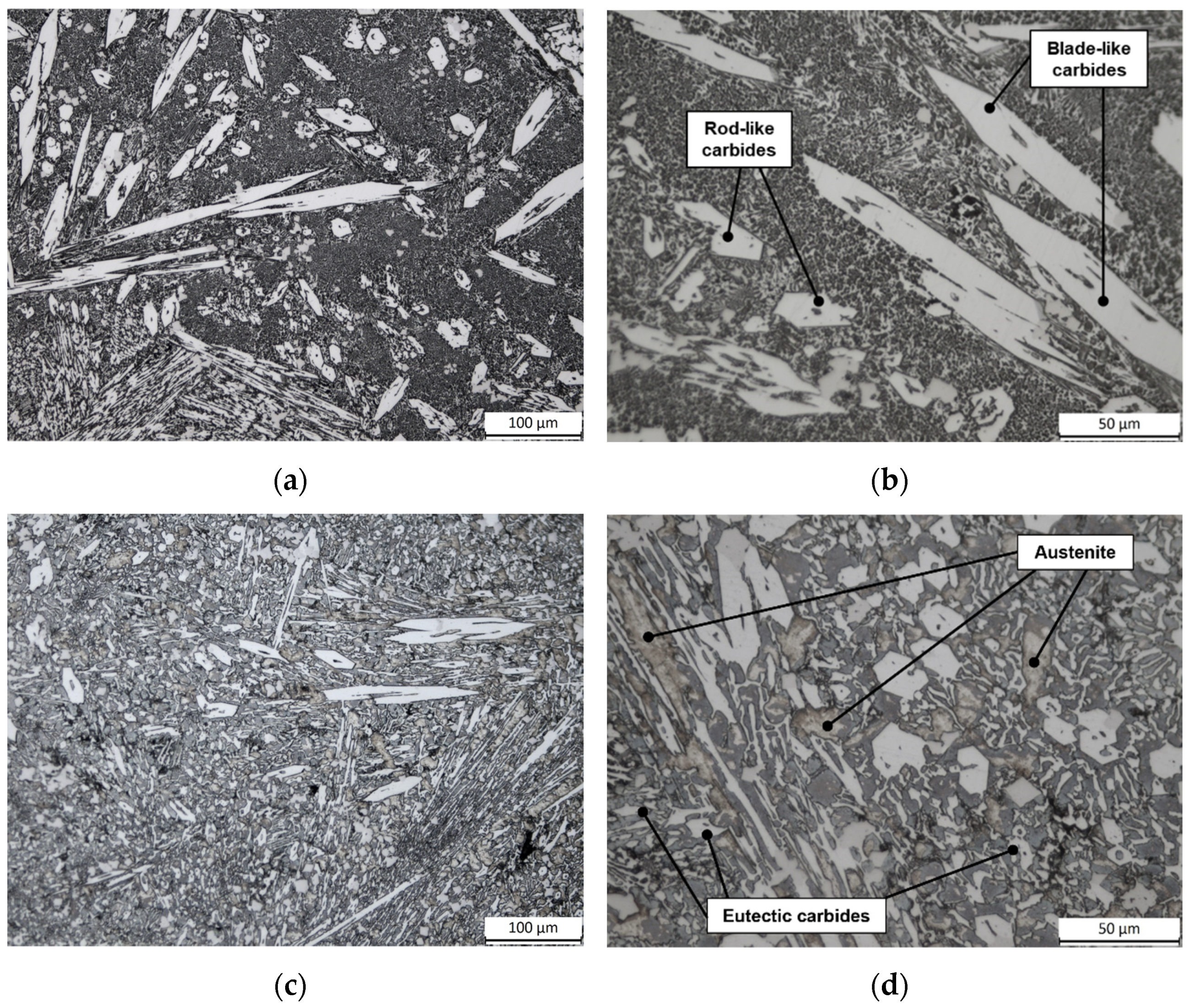
3.1. Microstructures of the HCCIs in the as-Received Condition

Figure 2 shows OM micrographs of the alloys in the as-received conditions. Alloy 1 (Figure 2a,b) is composed of pro-eutectic M7C3 carbides, including rod-like and blade-like shapes. The formation and growth of primary carbides during solidification occur, with their long axes parallel to the direction of the heat flow. Such primary carbides are embedded in a matrix of eutectic carbides and martensite. Alloy 2 (Figure 2c,d) shows a microstructure consisting of pro-eutectic carbides, both in the blade- and in rod-like forms as the ones observed for Alloy 1, surrounded by a matrix of eutectic carbides, austenite, and small amounts of martensite (the latter is not resolved by OM but in the following SEM micrographs).

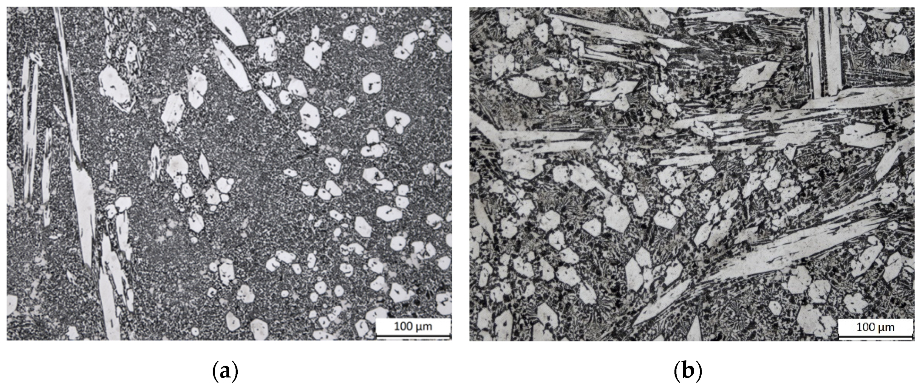
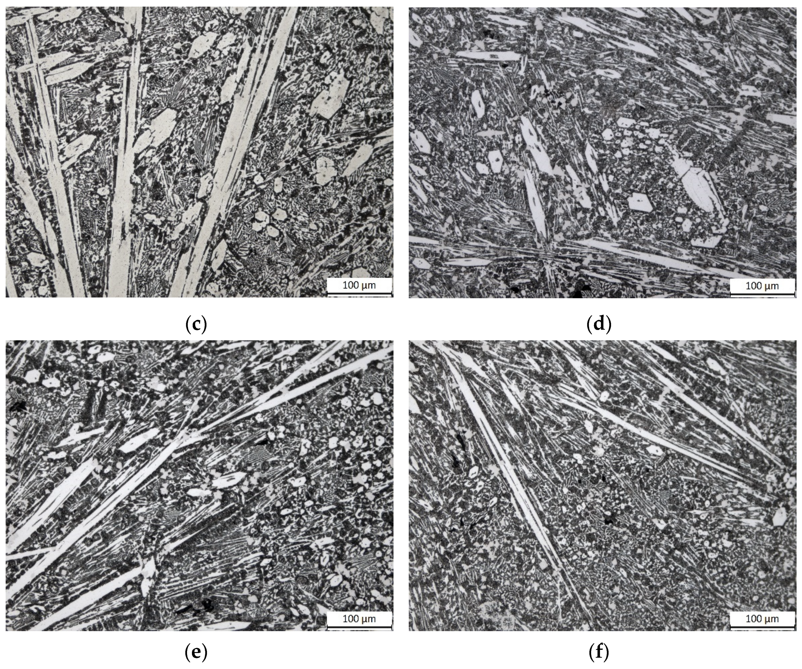
3.2. Microstructures of the HCCIs in the Heat-Treated Conditions
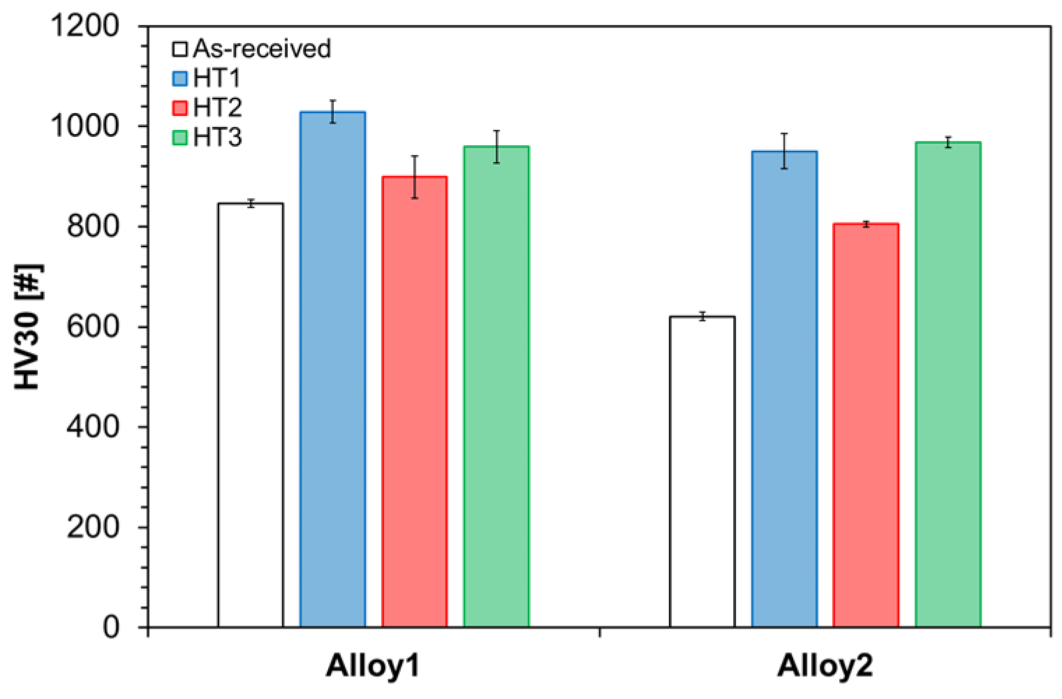
Low magnification OM micrographs of Alloy 1 and Alloy 2 in the heat-treated conditions are reported in Figure 3. Considering that primary carbides form directly from liquid, i.e., they are the result of the solidification path, they do not undergo significant changes during subsequent heat treatment processes: regardless of the alloys and the heat treatment route, OM micrographs of Figure 3 show blade- and rod-like M7C3 carbides in all cases, similarly to the as-received condition.
The precipitation of secondary carbides was detected by SEM investigations: Figure 4 shows BSE-SEM micrographs of Alloy 1 for the as-received condition (Figure 4a) and after heat treatments (Figure 4b–d), i.e., HT1, HT2 and HT3 condition, respectively. As seen, the as-received condition shows a network of eutectic M7C3 carbides within the surrounding martensitic matrix. Regardless of the considered heat treatments, the destabilized structures display the precipitation of secondary carbides in the martensitic matrix (Figure 4b–d). Different sizes and distribution of secondary carbides are detectable: after HT1 treatment, they appear as fine granular distributed particles (Figure 4b), whereas after HT2 and HT3 treatments, the amount of carbides decreases, their size becomes coarser, and they display a rounded shape (Figure 4c,d).
As observed for Alloy 1, also for Alloy 2 the changes involved the eutectic carbides and the matrix’s microstructure. In the as-received condition, Alloy 2 shows the presence of martensite formed close to the M7C3 carbides (see the BSE-SEM micrograph of Figure 5a). It is worth noting that after heat treatment, the overall transformation of austenite into martensite occurred, as well as the dissolution of eutectic carbides and the precipitation of secondary carbides (Figure 5b–d). As observed for Alloy 1, HT1 heat treatment promoted greater precipitation of secondary carbides as fine granular particles (Figure 5b). Conversely, coarsening of carbides is detectable after HT2 treatment: Figure 5c displays the extensive precipitation of large rod-like secondary carbides. Moreover, HT3 contributed to the agglomeration of secondary carbides (Figure 5d), although their number per unit area is significantly decreased compared to HT1 and HT2 treatments.

3.3. Bulk Hardness

The effect of the heat treatment routes was also investigated through hardness measurements, as reported in the graph in Figure 6. Considering the as-received condition, Alloy 1 shows a higher bulk hardness (846 ± 8 HV30) than Alloy 2 (621 ± 9 HV30) due to the martensitic microstructure of the matrix as observed in the above-reported microstructures (see Figure 4 and Figure 5). It can be noted that the heat treatments are effective in increasing the hardness with respect to the as-received condition both for Alloy 1 and Alloy 2. This is related to the martensitic transformation of the matrix (for Alloy 2) and the precipitation of secondary carbides. Concerning the hardness values of Alloy 1, it can be observed that HT1 treatment shows the highest values (1029 ± 23 HV30) in comparison to HT2 (899 ± 42 HV30) and HT3 (959 ± 32 HV30) routes. As for Alloy 2, it should be pointed out that the lowest value was observed with HT2 treatment (805 ± 6 HV30). For Alloy 2, HT1 and HT3 treatments show comparable hardness (950 ± 35 HV30 and 968 ± 11 HV30).

3.4. XRD

As stated above, the destabilization treatment promoted the precipitation of secondary carbides and, in turn, the reduction of C and Cr contents that raises the Ms temperature and thus the austenite to martensite transformation. Table 4 summarizes the weight percentages of the identified phases in the as-received and heat-treated samples for both Alloy 1 and Alloy 2 resulting from the Rietveld analyses. It is worth noting that, both for Alloy 1 and Alloy 2, the identified phases in the as-received condition are the same as the heat-treated condition: austenite γ, martensite α, M7C3 and NbC are the identified phases in Alloy 2, while Alloy 1 also has the M23C6 type carbides. As expected, Alloy 1 and Alloy 2 show a higher content of the martensite phase in the heat-treated samples in comparison with the as-received ones. As expected, all the investigated heat treatments promote an increase in the martensite content, which is related to the reduction of the retained austenite content with respect to the as-received condition. Indeed, secondary carbide precipitation depletes the austenitic matrix in Cr and C contents and, in turn, such depletion increases the Ms temperature promoting the formation of martensitic structures [49,50]. This affects the residual austenite content that decreases for Alloy 1 from 6.77% up to 0.35% for HT1 ad for Alloy 2 from 33.33% up to 1.10% for HT3. More specifically, for Alloy 2, the amount of austenite is comparable for HT1 and HT2 and in the order of 20–30 wt.%, while it is marginal for HT3 condition.

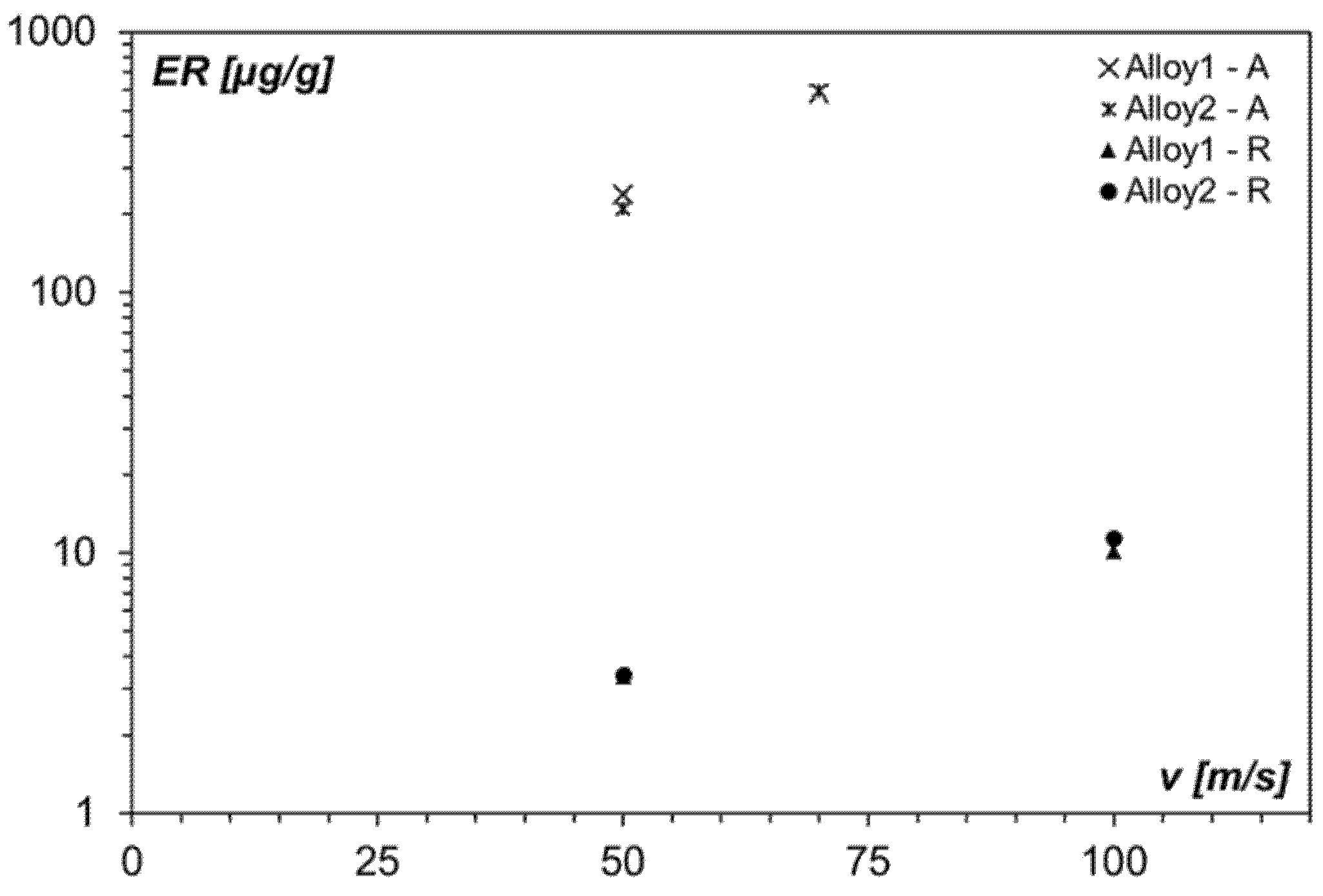
3.5. Erosion Behavior in the as-Received Condition

Figure 7 displays the erosion tests result for Alloy 1 and Alloy 2 in the as-received condition, considering the effects of the impact velocity v and the erodent, i.e., raw meal powder (labeled as R) and Al2O3 (labeled as A), on the ER values. With the same erodent powder, the erosive wear resistance of both the alloys is comparable and exhibits the same trend as a function of the impact velocity, that is the increment of ER with increasing the impact velocity. By contrast, the erodent particle’s type affects the magnitude of the damage since for raw meal powder the ER is less than 10 µg/g even for the highest impact velocity tested, whereas for Al2O3 powder is between one and two orders of magnitude higher. Hence, it can be stated that Alloy 1 and Alloy 2 offer good erosion resistance when the erodent particles are softer than the target material, i.e., raw meal powder. It should be pointed out that the raw meal powder and the Al2O3 have different particles’ mean diameters that, in turn, affect the kinetic energy, i.e., for Al2O3 it results one thousand times greater. Although the analysis of the erosive resistance of the alloys with equal kinetic energy was beyond the scope of the present study, the role of this parameter is briefly discussed below.

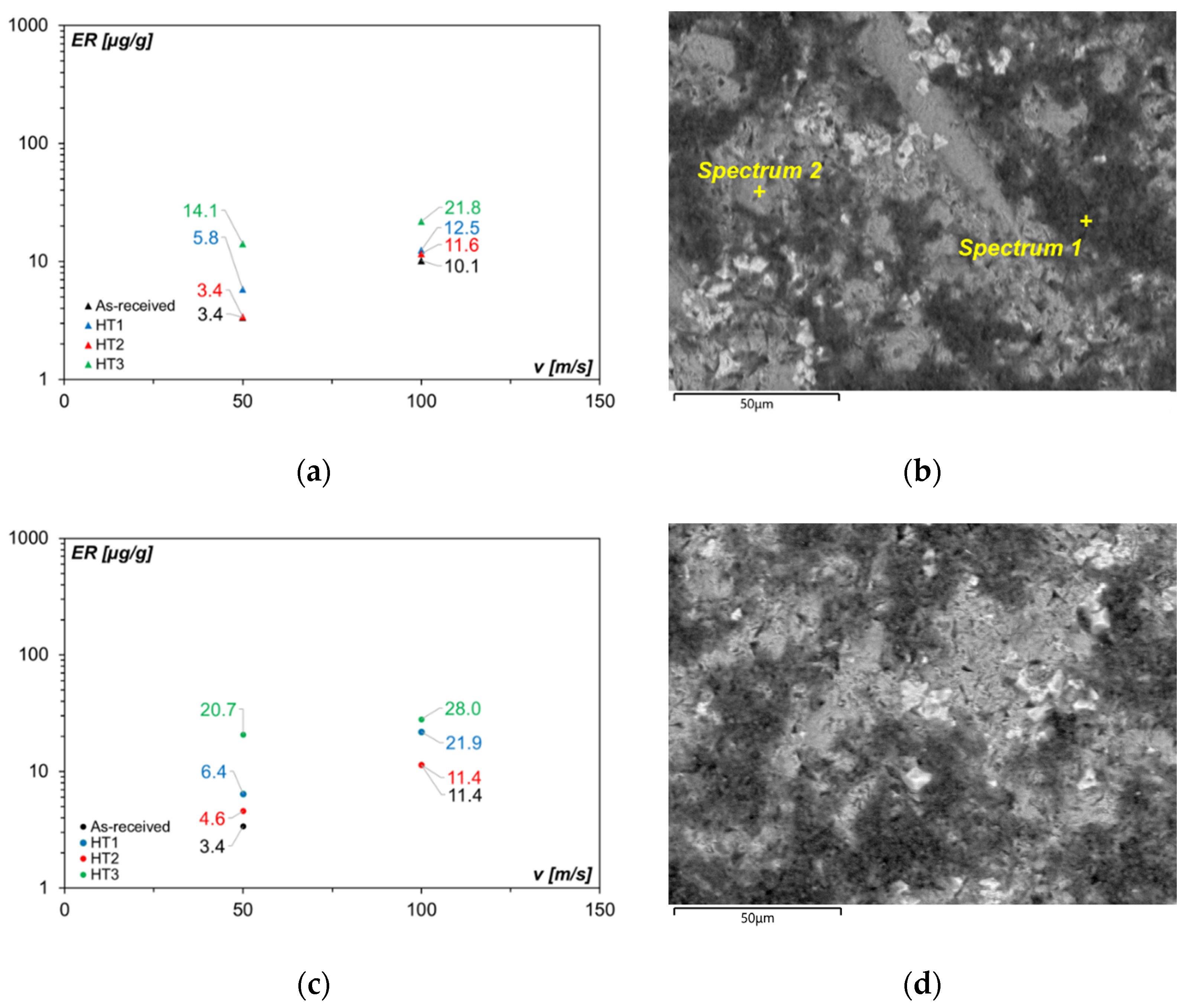
3.6. Erosion Behavior in the Heat-Treated Conditions

The effect of heat treatment on the erosion resistance was then evaluated for fixed alloy and erodent powder as a function of the impact velocity. Figure 8 shows the erosion behavior of Alloy 1 (Figure 8a) and Alloy 2 (Figure 8c) tested with Al2O3 powder. As can be seen, regardless of impact velocity and alloy composition, the lowest values of ER are always for the as-received condition. Besides, from the comparison between Alloy 1 and Alloy 2, it is observed that at the low impact velocity the ER of Alloy 1 (238.2 µg/g) is 13% greater than the one of Alloy 2 (210.3 µg/g), whereas at high impact velocity the ER are comparable. As for the heat-treated conditions, irrespective of impact velocity and alloy composition, the samples treated with HT3 route exhibit in all the tested conditions the lower erosion resistance, i.e., the highest values of ER. Hence, it can be inferred that the bulk hardness of the material is not an index of its erosion resistance, i.e., that only hardness affects the erosive wear behavior.
Images of the worn surfaces, taken with SEM, revealed the same erosion mechanism for all the investigated heat treatments. As an example, the worn surfaces of TT2 for Alloy 1 and the worn surfaces of TT3 for Alloy 2 are depicted. The images suggest extensive plastic deformation, deep craters, and big flakes.
With softer erodent particles, i.e., raw meal powder, again the highest ER values are displayed for the HT3 condition, both for Alloy 1 and Alloy 2 and irrespective of the impact velocity (Figure 9). As earlier mentioned for Al2O3 powder, from the comparison between Alloy 1 and Alloy 2 in the as-received condition, it comes out that irrespective of the impact velocity the ER are comparable and hence they are not dependent on alloy’s hardness. Once again, bulk hardness is not an exhaustive index of erosion resistance. However, it is worth noting that with softer erodent particles, the lowest values of ER are for the as-received condition, but the highest values of ER are about three times greater both for Alloy 1 (Figure 9a) and Alloy 2 (Figure 9c). These experimental findings suggested investigating the ER as a function of the relative hardness between erodents and alloy, as described later.
Representative images of the worn surfaces suggest extensive erosion of the matrix. Such evidence led us to believe that TT3 gave the hardest matrix with the lowest fracture toughness. The small raw meal powder hits this brittle matrix and promotes the highest erosion rate data.

3.7. Erosion Behavior vs. Hardness Ratio

As already mentioned, the effect of the heat treatments on the ER cannot be explained on the basis of the bulk hardness alone. As suggested in the literature [51], the relative hardness, i.e., the ratio of the hardness of the erodent He to that of the target material Ht, is one of the critical parameters that affect the ER. Figure 10 shows ER data versus the He/Ht ratio for all the tested conditions. The hardness of the erodents was taken from the literature [19] and assumed to be 412 HV0.1 and 1875 HV0.1 for raw meal powder and Al2O3 powder, respectively. The hardness of the target material was taken as a function of the considered condition, i.e., as-received or heat-treated, as reported in Figure 6. The proposed ER- He/Ht plot displays all the obtained values for Alloy 1 and Alloy 2 for both the tested impact velocities and for the erodents powders (in Figure 10 displayed as colored circle markers together with the associated impact velocity and erodent’s type, A is Al2O3 powder, R is raw meal powder). The dotted colored lines in Figure 10 are the powder trendline for each erodent-impact velocity set, together with the associated equation.
Considering the direct proportionality between the ER and the particle impact velocity [52], the kinetic energy of the impact particles was computed from the above-reported particle’s mean diameters and from the density values taken from the literature [19]. The kinetic energy values for the raw meal powder are 1.12 × 10⁻¹⁰ and 4.48 × 10⁻¹⁰, for the 50 m/s and 100 m/s impact velocities, respectively. The kinetic energy values for the Al2O3 powder are 3.19 × 10⁻⁷ and 6.25 × 10⁻⁷, for the 50 m/s and 70 m/s impact velocities, respectively. Figure 10 also displays the upward-pointing triangle and the diamond markers that refer to the ER- He/Ht data for Alloy 1 and Alloy 2 grouped for the same impact velocity. Since for the Al2O3 powder, the impact velocity is 70 m/s (rather than 100 m/s), the two grouped data could be assumed as “low impact velocities” and “medium impact velocities”. The dashed black lines in Figure 10 are the powder trendlines for the “low impact velocities” and for the “medium impact velocities”.
As a result, it can be concluded that the dashed black lines in Figure 10 are iso-kinetic energy curves, whereas the colored dotted lines are iso-velocity curves for each erodent-velocity set. Focusing on the latter curves, it can be observed that, regardless of the erodent, by increasing the hardness of the target material the ER increases. This result is consistent with a previous study of Sapate and Rama Rao [18]. As regards the Al2O3 powder, the powder trend lines of the considered impact velocities show comparable values of the exponent (−0.238 and −0.0552 for 70 m/s and 50 m/s, respectively), suggesting that the ER is independent on the He/Ht ratio. Conversely, for the raw meal powder, the exponent values are considerably different (−1.134 and −3.178 for 100 m/s and 50 m/s, respectively), indicating that He/Ht ratio affects the ER. It can be inferred that such behavior is related with the He/Ht ratio: if the He/Ht ratio is less than 1, the ER is dependent on the ratio of the hardness of the erodent to that of the target material, whereas if the He/Ht ratio is higher than 1, the ER is not affected by the He/Ht ratio.

4. Discussion

The microstructural and erosive wear resistance of two HCCIs both in the as-received condition and after three different destabilization heat treatments were investigated. The role of the type of erodent was also considered by comparing a raw meal powder commonly used in cement factories and Al2O3 powder, commonly taken as reference powder in erosive tests.
Optical microscopy and scanning electron microscopy analyses of the as-received samples revealed the typical microstructure of an hypereutectic alloy, which is responsible for the excellent combination of high hardness and superior wear resistance of such alloys [53]. The coupled microstructural observations and the XRD analysis confirmed the M7C3 type for the observed eutectic carbides, typical for the 15–30 wt.% Cr cast irons [4,54].
Eutectic carbides are almost unaffected by the solubilization heat treatment [2], which instead involves microstructural modifications of the matrix. SEM observations, XRD analysis and hardness values set out the role of the heat treatment route in the precipitation of secondary carbides. Consistent with previous studies [4,35,49,55], during soaking at temperatures within the 800–1000 °C, carbon and chromium from the matrix react to form small carbide particles. Besides, the precipitation of secondary carbides promotes the depletion of the austenite phase from alloying elements and, in turn, the increment of the martensite-start temperature (Ms). As a result, the transformation of austenite into martensite upon cooling takes place [30,31,38,56]. Concerning Alloy 1, whose microstructure in the as-received condition is characterized by a martensitic matrix and a small amount (around 7 wt.%) of austenite, all the considered heat treatment routes promoted the reduction of the austenite content up to less than 1 wt.% and the increment of the amount of martensite up to 40–45 wt.%. This microstructural modification was observed through SEM investigations and confirmed by XRD data. Conversely, Alloy 2 in the as-received condition is characterized by an austenitic microstructure and martensite at the matrix/carbide interface: the formation of martensite in close vicinity of carbides has been reported by Tabrett and Sare [31] as the result of the local depletion of the austenite from alloying addition. The same heat treatment routes applied to Alloy 2 led to different weight percentages of the austenite and martensite phases, depending on the temperature and soaking times. With respect to the as-received condition, HT1 led to a reduction of the austenite content (from about 30 wt.% to about 20 wt.%), and an increment of the martensite content (from about 20 wt.% to about 45 wt.%). As for HT2, it led to a negligible modification of the austenite content and an increment of the martensite content (from about 20 wt.% to about 40 wt.%). By contrast, HT3 promoted a remarkable reduction of the austenite content (from about 30 wt.% to about 1 wt.%), and an increment of the martensite content (from about 20 wt.% to about 55 wt.%).
These overall crystallographic findings could be put in relation to the bulk hardness values. For Alloy 1, despite the comparable crystallographic findings (see Table 2) for all the considered heat treatment routes in terms of martensite and retained austenite contents (about 40 wt.% of martensite and less than 1 wt.% of retained austenite), the bulk hardness results show some differences and HT1 has the highest hardness compared to HT2 and HT3. These experimental findings, in connection with the BSE-SEM observations (Figure 4), suggest that the fine and well-dispersed secondary carbides promoted by the highest temperature and soaking time, reflected in the highest bulk hardness. According to Bedolla-Jacuinde et al. [49], the hardness is dependent on the strengthening of the matrix, which, in turn, is affected by the soaking time and temperature of the heat treatment.
The authors compared three different destabilization temperatures, i.e., 900 °C, 1000 °C and 1150 °C, finding an increment of bulk hardness with increasing the soaking time up to a maximum value and then a decrement at higher soaking time. Nonetheless, they also found that at a given soaking time, the bulk hardness decrease as the temperature increases. Besides, the amount of retained austenite is not proportional to bulk hardness: within the 10 min–100 min range, the retained austenite content decreases both for the 900 °C and 1000 °C destabilization temperatures but, on the other hand, the bulk hardness increases for the 900 °C and decreases for the 1000 °C. In this regard, the authors suggest that the increase in microhardness of the matrix observed for 900 °C destabilization temperature is influenced by two factors as the soaking time increases: the precipitation of secondary carbides that strengthens the matrix by particle dispersion together with the increase in martensite volume fraction. In addition, diminishing microhardness after 3 h soaking time has been attributed to the secondary carbide coarsening. Hence, in accordance with [49], the hardness of the matrix is influenced by both the precipitation of secondary carbides and the martensite volume fraction but also the number of precipitated particles per unit area, which, in turn, depends on temperature and soaking time. Conversely, for Alloy 2 the considered heat treatment routes determined remarkable differences among the crystallographic data among the investigated heat treatment routes. The bulk hardness after HT1 and HT3 is comparable despite the XRD data show a remarkable difference in the content of retained austenite, i.e., around 20 wt.% for HT1 and around 1 wt.% for HT3. In addition, as for HT2 treatment, the increment with respect to the as-received condition is lower than the ones observed for HT1 and HT3. The content of retained austenite (around 30 wt.%) together with the SEM observations (see Figure 5c) suggest the role of secondary carbide coarsening. Regardless of the considered chemical composition of the HCCI, HT1 showed a considerably high number of precipitates per unit of area (see Figure 4b and Figure 5b) compared with the other heat treatments. This experimental finding is in keeping with the observations of Kishore et al. [57], which showed higher precipitation of secondary carbides as the temperature increases from 700 °C to 1000 °C. Such an increment has been associated with faster diffusion kinetics at a higher temperature compared to lower destabilizing temperatures.
Besides these findings, the obtained ER data, both for the raw meal powder and for Al2O3, were not directly related to the hardness results. Regardless of impact velocity and alloy composition, the lowest values of ER were always for the as-received condition and the highest hardness data were associated with the highest ER data, i.e., the lowest erosion resistance. It has been assessed that both carbides and matrix contribute to wear resistance: size, volume fraction and matrix characteristics affect the wear resistance and the fracture toughness of the alloy [2]. In addition, after heat treatment, the reduction of fracture toughness due to the martensite content and the associated crack propagation after abrasion wear tests was observed [42]. Although the wear resistance of HCCIs could be increased by destabilization of the austenitic matrix, promoting the precipitation of small secondary carbides in the transformed martensite matrix [37,40], the present study revealed that the proposed heat treatment routes were effective in increasing the bulk hardness, but the role of both fracture toughness resulting from heat treatment and the erodent powder features, in terms of size and hardness, should be taken into account to comprehensive describe the erosion resistance of such alloys.
Previous studies [19] have dealt with the erosive wear behavior of HCCIs by comparing several erodent particles describing the ER in relation to impact angle, impact velocity and relative hardness between erodent and target material. The present study, by considering the combined effect of different heat treatment routes and erodents, enabled to (i) confirm that for solid particle erosion, hardness is not a comprehensive index of erosion resistance [14,58], (ii) study the role of the relative hardness between erodent and target on the ER and (iii) highlight the need for a detailed investigation on the role of erodent’s size with respect to microstructural and mechanical features (i.e., hardness, carbide volume fraction, secondary carbides size and distribution, fracture toughness) of the alloy. Unlike [19], this study has considered the relative hardness by varying the state of the substrate, i.e., as-received and heat-treated, showing that hard carbides contribute to erosion resistance but also the hardness and the toughness of the matrix play a key role. In this respect, the obtained results could be directly compared to each other, and they are highly representative since they are entirely unaffected by the parameters related to the erodent’s characteristics and related uncertainty. With reference to the He/Ht ratio, the observed high (for He/Ht ratio higher than 1) and weak (for He/Ht ratio lower than 1) dependence enable engineers and designers to properly account for the almost opposite behavior: high sensitivity to impact velocity for the He/Ht ratio lower than 1–low impact velocity condition, low sensitivity to impact velocity for the He/Ht ratio higher than 1. It is assumed that the observed behavior is caused by the mechanical interaction between erodent and substrate, as suggested by [59,60], since that part of the energy of the erodent particle is dissipated on fragmentation. As a result, for a substrate with low hardness with respect to the erodent, the role of the substrate is negligible with respect to that of the erodent particle. Conversely, for a substrate with higher hardness than the erodent, the high sensitivity is related to the energy dissipated by the particles, as revealed by the different equations for 50 m/s and 100 m/s. Further investigations are needed to provide greater insight into the role of kinetic energy on erosive wear mechanisms.

5. Conclusions

In this work, the combined effect of heat treatment route and erodent type on the solid particle erosion behavior of two HCCIs was investigated. Based on the experimental observations, the concluding remarks can be summarized as follows.
  • For all the investigated heat treatments, the precipitation of secondary carbides and, for Alloy 2, the overall transformation of the austenite into martensite were detected. Size and distribution of secondary carbides were affected by the temperature and time parameters: after HT1 treatment (the highest temperature and soaking time), they always appear as fine granular distributed particles.
  • The obtained bulk hardness values were influenced not only by the retained austenite and martensite contents but also depended on soaking temperature and time that affects carbides’ dimension and distribution.
  • For the same erodent powder, the ER of both Alloy 1 and Alloy 2 is comparable, and it increased as the impact velocity increased. Alloy 1 and Alloy 2 offered good erosion resistance when the erodent particles were softer than the target material: the ER with Al2O3 powder is between one and two orders of magnitude higher with respect to raw meal powder.
  • The ER of Alloy 1 and Alloy 2 tested with both raw meal powder and Al2O3 powder worsened in the heat-treated conditions. Besides, irrespective of impact velocity and alloy composition, the samples treated with HT3 route, exhibit in all the tested conditions the highest ER. With raw meal powder, the lowest values of ER were for the as-received condition, but the highest values of ER were about three times greater. Hence, the overall hardness of the alloy is not a comprehensive index of erosive wear resistance.
  • The He/Ht ratio affects the ER: whether it is less than 1, the ER showed a stronger dependence on the ratio of the hardness of the erodent to that of the target material.
These results have important implications for the proper design of components where the sensitivity to impact velocity is a key parameter. Moreover, this study establishes a groundwork for future studies focused on the role of kinetic energy in erosive wear mechanisms.

Author Contributions

Conceptualization, A.F. and A.S.; methodology, A.S.; investigation, N.Z. and G.C.; data curation A.S. and G.C.; writing—original draft preparation, A.F.; writing—review and editing, A.S.; visualization, A.S.; supervision. All authors have read and agreed to the published version of the manuscript.

Funding

This research received no external funding.

Institutional Review Board Statement

Not applicable.

Informed Consent Statement

Not applicable.

Data Availability Statement

Not applicable.

Acknowledgments

The authors wish to gratefully acknowledge Eng. Paolo Saccenti of Boldrocchi S.r.l. (Biassono, Monza-Brianza, Italy) for the technical support in this activity. Thanks are also due to Gian Luca Garagnani, Mattia Merlin and Michele Pinelli for the coordination and support.

Conflicts of Interest

The authors declare no conflict of interest.

References

  1. Studnicki, A.; Kilarski, J.; Przybył, M.; Suchoń, J.; Bartocha, D. Wear resistance of chromium cast iron—research and application. Manuf. Eng. 2006, 16, 63–73. [Google Scholar]
  2. Tabrett, C.P.; Sare, I.R.; Ghomashchi, M.R. Microstructure-property relationships in high chromium white iron alloys. Int. Mater. Rev. 1996, 41, 59–82. [Google Scholar] [CrossRef]
  3. Liu, S.; Zhou, Y.; Xing, X.; Wang, J.; Ren, X.; Yang, Q. Growth characteristics of primary M7C3 carbide in hypereutectic Fe-Cr-C alloy. Sci. Rep. 2016, 6, 32941. [Google Scholar] [CrossRef] [PubMed] [Green Version]
  4. Wiengmoon, A. Carbides in high chromium cast irons. Naresuan Univ. Eng. J. 2011, 6. [Google Scholar]
  5. Ma, S.; Xing, J.; He, Y.; Li, Y.; Huang, Z.; Liu, G.; Geng, Q. Microstructure and crystallography of M7C3 carbide in chromium cast iron. Mater. Chem. Phys. 2015. [Google Scholar] [CrossRef]
  6. Chotěborský, R.; Hrabě, P.; Müller, M.; Válek, R.; Savková, J.; Jirka, M. Effect of carbide size in hardfacing on abrasive wear. Res. Agric. Eng. 2009, 55, 149–158. [Google Scholar] [CrossRef] [Green Version]
  7. Buchely, M.F.; Gutierrez, J.C.; León, L.M.; Toro, A. The effect of microstructure on abrasive wear of hardfacing alloys. Wear 2005, 259, 52–61. [Google Scholar] [CrossRef]
  8. Correa, E.O.; Alcântara, N.G.; Valeriano, L.C.; Barbedo, N.D.; Chaves, R.R. The effect of microstructure on abrasive wear of a Fe–Cr–C–Nb hardfacing alloy deposited by the open arc welding process. Surf. Coatings Technol. 2015, 276, 479–484. [Google Scholar] [CrossRef]
  9. Chotěborský, R.; Hrabě, P.; Müller, M.; Savková, J.; Jirka, M. Abrasive wear of high chromium Fe-Cr-C hardfacing alloys. Res. Agric. Eng. 2008, 54, 192–198. [Google Scholar] [CrossRef]
  10. Cruz-Crespo, A.; Fernández-Fuentes, R.; Ferraressi, A.V.; Gonçalves, R.A.; Scotti, A. Microstructure and Abrasion Resistance of Fe-Cr-C and Fe-Cr-C-Nb Hardfacing Alloys Deposited by S-FCAW and Cold Solid Wires. Soldag. Inspeção 2016, 21, 342–353. [Google Scholar] [CrossRef] [Green Version]
  11. Jilleh, A.; Kishore Babu, N.; Thota, V.; Anis, A.L.; Harun, M.K.; Talari, M.K. Microstructural and wear investigation of high chromium white cast iron hardfacing alloys deposited on carbon steel. J. Alloys Compd. 2021, 857, 157472. [Google Scholar] [CrossRef]
  12. Jindal, C.; Singh Sidhu, B.; Kumar, P.; Singh Sidhu, H. Performance of hardfaced/heat treated materials under solid particle erosion: A systematic literature review. Mater. Today Proc. 2022, 50, 629–639. [Google Scholar] [CrossRef]
  13. Tarodiya, R.; Levy, A. Surface erosion due to particle-surface interactions—A review. Powder Technol. 2021, 387, 527–559. [Google Scholar] [CrossRef]
  14. Chatterjee, S.; Pal, T.K. Solid particle erosion behaviour of hardfacing deposits on cast iron—Influence of deposit microstructure and erodent particles. Wear 2006, 261, 1069–1079. [Google Scholar] [CrossRef]
  15. Purba, R.H.; Shimizu, K.; Kusumoto, K.; Todaka, T.; Shirai, M.; Hara, H.; Ito, J. Erosive wear characteristics of high-chromium based multi-component white cast irons. Tribol. Int. 2021, 159, 106982. [Google Scholar] [CrossRef]
  16. Adler, T.A.; Doğan, Ö.N. Erosive wear and impact damage of high-chromium white cast irons. Wear 1999, 225–229, 174–180. [Google Scholar] [CrossRef]
  17. Sapate, S.G.; Rama Rao, A.V. Effect of material hardness on erosive wear behavior of some weld-deposited alloys. Mater. Manuf. Process. 2002, 17, 187–198. [Google Scholar] [CrossRef]
  18. Sapate, S.G.; Rama Rao, A.V. Effect of carbide volume fraction on erosive wear behaviour of hardfacing cast irons. Wear 2004, 256, 774–786. [Google Scholar] [CrossRef]
  19. Sapate, S.G.; RamaRao, A.V. Erosive wear behaviour of weld hardfacing high chromium cast irons: Effect of erodent particles. Tribol. Int. 2006, 39, 206–212. [Google Scholar] [CrossRef]
  20. Nguyen, V.B.; Nguyen, Q.B.; Zhang, Y.W.; Lim, C.Y.H.; Khoo, B.C. Effect of particle size on erosion characteristics. Wear 2016, 348–349, 126–137. [Google Scholar] [CrossRef]
  21. Stevenson, A.N.; Hutchings, I. Wear of hardfacing white cast irons by solid particle erosion. Wear 1995, 186–187, 150–158. [Google Scholar] [CrossRef]
  22. Fortini, A.; Suman, A.; Vulpio, A.; Merlin, M.; Pinelli, M. Microstructural and erosive wear characteristics of a high chromium cast iron. Coatings 2021, 11, 490. [Google Scholar] [CrossRef]
  23. Filipovic, M.; Kamberovic, Z.; Korac, M.; Gavrilovski, M. Microstructure and mechanical properties of Fe-Cr-C-Nb white cast irons. Mater. Des. 2013, 47, 41–48. [Google Scholar] [CrossRef]
  24. Lin, C.-M.; Chang, C.-M.; Chen, J.-H.; Wu, W. The effects of additive elements on the microstructure characteristics and mechanical properties of Cr–Fe–C hard-facing alloys. J. Alloys Compd. 2010, 498, 30–36. [Google Scholar] [CrossRef]
  25. Tang, X.H.; Chung, R.; Li, D.Y.; Hinckley, B.; Dolman, K. Variations in microstructure of high chromium cast irons and resultant changes in resistance to wear, corrosion and corrosive wear. Wear 2009, 267, 116–121. [Google Scholar] [CrossRef]
  26. Li, P.; Yang, Y.; Shen, D.; Gong, M.; Tian, C.; Tong, W. Mechanical behavior and microstructure of hypereutectic high chromium cast iron: The combined effects of tungsten, manganese and molybdenum additions. J. Mater. Res. Technol. 2020, 9, 5735–5748. [Google Scholar] [CrossRef]
  27. Zhi, X.; Xing, J.; Fu, H.; Xiao, B. Effect of niobium on the as-cast microstructure of hypereutectic high chromium cast iron. Mater. Lett. 2008, 62, 857–860. [Google Scholar] [CrossRef]
  28. Bedolla-Jacuinde, A.; Correa, R.; Quezada, J.G.; Maldonado, C. Effect of titanium on the as-cast microstructure of a 16%chromium white iron. Mater. Sci. Eng. A 2005, 398, 297–308. [Google Scholar] [CrossRef]
  29. Liu, S.; Shi, Z.; Xing, X.; Ren, X.; Zhou, Y.; Yang, Q. Effect of Nb additive on wear resistance and tensile properties of the hypereutectic Fe-Cr-C hardfacing alloy. Mater. Today Commun. 2020. [Google Scholar] [CrossRef]
  30. Karantzalis, A.E.; Lekatou, A.; Diavati, E. Effect of Destabilization Heat Treatments on the Microstructure of High-Chromium Cast Iron: A Microscopy Examination Approach. J. Mater. Eng. Perform. 2009, 18, 1078–1085. [Google Scholar] [CrossRef]
  31. Tabrett, C.P.; Sare, I.R. Effect of high temperature and sub-ambient treatments on the matrix structure and abrasion resistance of a high-chromium white iron. Scr. Mater. 1998. [Google Scholar] [CrossRef]
  32. Doğan, Ö.N.; Hawk, J.A.; Laird, G. Solidification structure and abrasion resistance of high chromium white irons. Metall. Mater. Trans. A 1997, 28, 1315–1328. [Google Scholar] [CrossRef]
  33. Doǧan, Ö.N.; Hawk, J.A. Effect of carbide orientation on abrasion of high Cr white cast iron. Wear 1995, 189, 136–142. [Google Scholar] [CrossRef] [Green Version]
  34. Maratray, F.; Poulalion, A. Austenite Retention in High-Chromium White Irons. Trans. Am. Foundrymen’s Soc. 1982, 90. [Google Scholar]
  35. Karantzalis, A.E.; Lekatou, A.; Kapoglou, A.; Mavros, H.; Dracopoulos, V. Phase Transformations and Microstructural Observations During Subcritical Heat Treatments of a High-Chromium Cast Iron. J. Mater. Eng. Perform. 2012, 21, 1030–1039. [Google Scholar] [CrossRef]
  36. Gasan, H.; Erturk, F. Effects of a destabilization heat treatment on the microstructure and abrasive wear behavior of high-chromium white cast iron investigated using different characterization techniques. Metall. Mater. Trans. A 2013, 44, 4993–5005. [Google Scholar] [CrossRef]
  37. Guitar, M.A.; Suárez, S.; Prat, O.; Duarte Guigou, M.; Gari, V.; Pereira, G.; Mücklich, F. High chromium cast irons: Destabilized-subcritical secondary carbide precipitation and its effect on hardness and wear properties. J. Mater. Eng. Perform. 2018, 27, 3877–3885. [Google Scholar] [CrossRef]
  38. Karantzalis, A.E.; Lekatou, A.; Mavros, H. Microstructural Modifications of As-Cast High-Chromium White Iron by Heat Treatment. J. Mater. Eng. Perform. 2009. [Google Scholar] [CrossRef]
  39. Gonzalez-Pociño, A.; Alvarez-Antolin, F.; Asensio-Lozano, J. Optimization of thermal processes applied to hypoeutectic white cast iron containing 25% Cr aimed at increasing erosive wear resistance. Metals 2020, 10, 359. [Google Scholar] [CrossRef] [Green Version]
  40. Gonzalez-Pociño, A.; Alvarez-Antolin, F.; Asensio-Lozano, J. Influence of thermal parameters related to destabilization treatments on erosive wear resistance and microstructural variation of white cast iron containing 18% Cr. application of design of experiments and rietveld structural analysis. Materials 2019, 12, 3252. [Google Scholar] [CrossRef] [Green Version]
  41. Gonzalez-Pociño, A.; Alvarez-Antolin, F.; Asensio-Lozano, J. Erosive wear resistance regarding different destabilization heat treatments of austenite in high chromium white cast iron, alloyed with Mo. Metals 2019, 9, 522. [Google Scholar] [CrossRef] [Green Version]
  42. Kim, C.K.; Lee, S.; Jung, J.-Y. Effects of heat treatment on wear resistance and fracture toughness of duo-cast materials composed of high-chromium white cast iron and low-chromium steel. Metall. Mater. Trans. A 2006, 37, 633–643. [Google Scholar] [CrossRef] [Green Version]
  43. He-Xing, C.; Zhe-Chuan, C.; Jin-Cai, L.; Huai-Tao, L. Effect of niobium on wear resistance of 15%Cr white cast iron. Wear 1993. [Google Scholar] [CrossRef]
  44. Aldi, N.; Casari, N.; Pinelli, M.; Suman, A.; Vulpio, A.; Saccenti, P.; Beretta, R.; Fortini, A.; Merlin, M. Erosion behavior on a large-sized centrifugal fan. In Proceedings of the 13th European Turbomachinery Conference on Turbomachinery Fluid Dynamics and Thermodynamics, Lausanne, Switzerland, 8–12 April 2019. [Google Scholar]
  45. Bedolla-Jacuinde, A.; Guerra, F.; Mejia, I.; Vera, U. Niobium Additions to a 15%Cr–3%C White Iron and Its Effects on the Microstructure and on Abrasive Wear Behavior. Metals 2019, 9, 1321. [Google Scholar] [CrossRef] [Green Version]
  46. Guitar, M.A.; Nayak, U.P.; Britz, D.; Mücklich, F. The Effect of Thermal Processing and Chemical Composition on Secondary Carbide Precipitation and Hardness in High-Chromium Cast Irons. Int. J. Met. 2020, 14, 755–765. [Google Scholar] [CrossRef] [Green Version]
  47. Suman, A.; Vulpio, A.; Fortini, A.; Fabbri, E.; Casari, N.; Merlin, M.; Pinelli, M. Experimental analysis of micro-sized particles time-wise adhesion: The influence of impact velocity and surface roughness. Int. J. Heat Mass Transf. 2021, 165, 120632. [Google Scholar] [CrossRef]
  48. Aldi, N.; Casari, N.; Pinelli, M.; Suman, A.; Vulpio, A.; Saccenti, P. Performance Modification of an Erosion-Damaged Large-Sized Centrifugal Fan. In Proceedings of the 13th ASME Turbo Expo 2021: Turbomachinery Technical Conference and Exposition, Virtual, 7–11 June 2021. [Google Scholar]
  49. Bedolla-Jacuide, A.; Arias, L.; Hernández, B. Kinetics of Secondary Carbides Precipitation in a High-Chromium White Iron. J. Mater. Eng. Perform. 2003, 12, 371–382. [Google Scholar] [CrossRef]
  50. Kim, C. X-ray method of measuring retained austenite in heat treated white cast irons. J. Heat Treat. 1979. [Google Scholar] [CrossRef]
  51. Sapate, S.G.; Haque, N. Effect of microstructure on slurry erosion behaviour of weld hardfacing alloys. Proc. Inst. Mech. Eng. Part L J. Mater. Des. Appl. 2011, 225, 49–59. [Google Scholar] [CrossRef]
  52. Finnie, I. Erosion of surfaces by solid particles. Wear 1960, 3, 87–103. [Google Scholar] [CrossRef]
  53. Lin, C.-M.; Chang, C.-M.; Chen, J.-H.; Hsieh, C.-C.; Wu, W. Microstructural evolution of hypoeutectic, near-eutectic, and hypereutectic high-carbon Cr-based hard-facing alloys. Metall. Mater. Trans. A 2009, 40, 1031–1038. [Google Scholar] [CrossRef]
  54. Pearce, J.T.H. Examination of M7C3 carbides in high chromium cast irons using thin foil transmission electron microscopy. J. Mater. Sci. Lett. 1983, 2, 428–432. [Google Scholar] [CrossRef]
  55. Wang, J.; Li, C.; Liu, H.; Yang, H.; Shen, B.; Gao, S.; Huang, S. The precipitation and transformation of secondary carbides in a high chromium cast iron. Mater. Charact. 2006, 56, 73–78. [Google Scholar] [CrossRef]
  56. Powell, G.L.F.; Laird, G. Structure, nucleation, growth and morphology of secondary carbides in high chromium and Cr-Ni white cast irons. J. Mater. Sci. 1992, 27, 29–35. [Google Scholar] [CrossRef]
  57. Kishore, K.; Kumar, U.; Dinesh, N.; Adhikary, M. Effect of Soaking Temperature on Carbide Precipitation, Hardness, and Wear Resistance of High-Chromium Cast Iron. J. Fail. Anal. Prev. 2020. [Google Scholar] [CrossRef]
  58. Gahr, K.-H.Z. Wear by hard particles. Tribol. Int. 1998, 31, 587–596. [Google Scholar] [CrossRef]
  59. Bitter, J.G.A. A study of erosion phenomena part I. Wear 1963, 6, 5–21. [Google Scholar] [CrossRef]
  60. Goodwin, J.E.; Sage, W.; Tilly, G.P. Study of Erosion by Solid Particles. Proc. Inst. Mech. Eng. 1969, 184, 279–292. [Google Scholar] [CrossRef]
Figure 1. (a) Sketch of the erosion test rig; (b) SEI-SEM images of the erodents used for erosive wear tests, raw meal powder and Al2O3 powder in the as-received condition.
Coatings 12 01218 g001
Figure 2. OM micrographs of the hardfacing alloys in the as-received condition: (a,b) Alloy 1, pro-eutectic M7C3 carbides (rod-like and blade-like shapes) in a matrix of eutectic carbides and martensite; (c,d) Alloy 2, pro-eutectic M7C3 carbides (rod-like and blade-like shapes) in a matrix of eutectic carbides, austenite, and traces of martensite.
Coatings 12 01218 g002
Figure 3. OM micrographs of the hardfacing alloys in the heat-treated conditions: (ac) Alloy 1 in HT1, HT2 and HT3 condition, respectively. Microstructure composed of pro-eutectic M7C3 carbides (rod-like and blade-like shapes) in a matrix of eutectic carbides and martensite; (df) Alloy 2 in HT1, HT2 and HT3 condition, respectively. Microstructure composed of pro-eutectic M7C3 carbides (rod-like and blade-like shapes) in a matrix of eutectic carbides, austenite, and traces of martensite.
Coatings 12 01218 g003aCoatings 12 01218 g003b
Figure 4. BSE-SEM analyses of Alloy 1: (a) as-received condition, (bd) after heat treatments: HT1, HT2 and HT3 condition, respectively. SEM/EDS chemical composition (wt.%) results for the selected regions labeled in the micrographs: Spectrum 1 C 7.93; Si 1.14; V 0.39; Cr 13.13; Mn 0.64; Fe 72.48; Cu 0.72; Nb 1.63; Mo 1.48; W 0.46. Spectrum 2 C 12.10; Si 0.36; Cr 30.22; Fe 52.22; Cu 0.48; Nb 1.64. Spectrum 3 C 16.55; Si 0.29; Ti 0.38; Cr 10.07; Fe 24.53; Cu 0.55; Nb 47.63.
Coatings 12 01218 g004
Figure 5. BSE-SEM micrographs of Alloy 2: (a) as-received condition, (bd) after heat treatments: HT1, HT2 and HT3 condition, respectively.
Coatings 12 01218 g005
Figure 6. Bulk hardness values for Alloy 1 and Alloy 2 in the as-received and heat-treated conditions.
Coatings 12 01218 g006
Figure 7. Erosion rate (ER) against impact velocity for the two investigated HCCIs, namely Alloy 1 and Alloy 2 in the as-received condition: comparison between erodent powders. A is Al2O3 powder, R is raw meal powder. For each point, the standard deviation of uncertainty associated with the ER value is the same dimension as the adopted indicator.
Coatings 12 01218 g007
Figure 8. Erosion behavior of Alloy 1 and Alloy 2 tested with Al2O3 powder. (a) Erosion rate (ER) against impact velocity for Alloy 1 in both as-received and heat-treated conditions. (b) BSE-SEM micrograph of the erosion crater, Alloy 1 in HT2 condition. (c) Erosion rate (ER) against impact velocity for Alloy 2 in both as-received and heat-treated conditions. (d) BSE-SEM micrograph of the erosion crater, Alloy 1 in HT3 condition. For each point of the plots, the standard deviation of uncertainty associated with the ER value is the same dimension as the adopted indicator. SEM/EDS chemical composition (wt.%) results for the selected regions labeled in the micro-graphs: Spectrum 1 C 3.73; O 35.12; Al 44.13; Si 0.34; P 1.51; Ca 0.24; Cr 5.51; Fe 9.41. Spectrum 2 C 12.83; O 12.23; Al 0.51; Ti 0.79; Cr 2.97; Fe 13.50; Nb 57.18. Spectrum 3 C 10.89; O 22.59; Al 8.83; Si 0.94; P 2.04; Ca 3.96; V 0.62; Cr 17.87; Fe 29.56; Mo 2.69.
Coatings 12 01218 g008
Figure 9. Erosion behavior of Alloy 1 and Alloy 2 tested with raw meal powder. (a) Erosion rate (ER) against impact velocity for Alloy 1 in both as-received and heat-treated conditions. (b) BSE-SEM micrograph of the erosion crater, Alloy 1 in HT2 condition. (c) Erosion rate (ER) against impact velocity for Alloy 2 in both as-received and heat-treated conditions. (d) BSE-SEM micrograph of the erosion crater, Alloy 1 in HT2 condition. For each point of the plots, the standard deviation of uncertainty associated with the ER value is the same dimension as the adopted indicator. SEM/EDS chemical composition (wt.%) results for the selected regions labeled in the micro-graphs: Spectrum 1 C 12.97; O 25.01; Mg 0.65; Al 1.82; Si 2.17; P 0.83; Ca 11.96; V 0.33; Cr 10.39; Mn 0.43; Fe 32.20; Mo 1.24. Spectrum 2 C 12.59; O 9.85; Al 0.55; Si 1.72; P 0.51; Ca 0.98; V 0.51; Cr 15.60; Mn 0.56; Fe 51.64; Nb 2.54; Mo 2.42; W 0.54.
Coatings 12 01218 g009
Figure 10. Erosion rate (ER) versus the ratio of erodent particle’s hardness and target material’s hardness (He/Ht). A is Al2O3 powder, R is raw meal powder for all the tested impact velocities for Alloy 1 and Alloy 2.
Coatings 12 01218 g010
Table 1. Chemical composition (wt.%) of the HCCIs.
AlloyComposition (wt.%)—Fe Balance
CMnSiCrMoNbWV
Alloy 13.83-0.8820.22-3.75--
Alloy 24.150.561.0821.042.784.090.860.69
Table 2. Characteristics of the adopted destabilization heat-treatment routes.
NameDwelling T [°C]Dwelling t [min]Cooling MediumMicrostructural EffectsReference
HT11000480OilBy using a long dwelling time at the destabilization temperature of austenite promote the increment of Ms temperature and, in turn, favors a decrease in retained austenite in the final microstructure.[41]
HT290030AirSecondary carbides precipitation occurred within the matrix, which was partially transformed into martensite. This increases the overall hardness and abrasive wear resistance.[45]
HT398090AirCarbide precipitation and austenite/martensite transformation caused the increment of the material hardness compared to the as-cast material.[46]
Table 3. Chemical composition (wt.%) and hardness of the raw meal powder.
AlCaSiCuNaHV0.1
69.09 ± 9.5624.52 ± 5.351.53 ± 0.782.98 ± 0.361.88 ± 0.52412 ± 95
Table 4. Weight percentages of the identified phases form the Rietveld analyses. The numbers in parentheses are the estimated standard deviations in the last significant digit.
AlloyConditionPhasesWt.%AlloyConditionPhasesWt.%
Alloy 1As-receivedα30.1 (4)Alloy 2As-receivedα22.3 (5)
γ6.8 (3)γ33.3 (5)
M7C347.9 (6)M7C338.4 (6)
NbC5.6 (1)NbC6.0 (1)
M23C69.7 (6)
HT1α39.4 (5) HT1α45 (2)
γ0.4 (1)γ20 (4)
M7C343.6 (5)M7C326 (2)
NbC9.1 (2)NbC9.5 (5)
M23C67.5 (6)
HT2A43.6 (6) HT2α39 (2)
Γ0.7 (1)γ30.9 (2)
M7C338.1 (6)M7C322 (4)
NbC6.4 (1)NbC8.6 (5)
M23C611.2 (7)
HT3α44.5 (6) HT3α56.9 (4)
γ0.7 (3)γ1.1 (2)
M7C342.8 (6)M7C335.5 (4)
NbC7.2 (2)NbC6.5 (2)
M23C64.8 (6)
Publisher’s Note: MDPI stays neutral with regard to jurisdictional claims in published maps and institutional affiliations.

