Abstract
Surface wear, as a major failure mode of gear systems, is an unavoidable phenomenon during the whole life of gears. It also induces other gear damages, such as fatigue cracks, surface pitting and spalling. Ultimately, those defects may result in the sudden failure of a gearbox transmission system, which can lead to a serious accident and unexpected economic loss. Therefore, it can provide huge cost and safety benefits to industries to monitor gear wear and predict its propagation. Gear wear raises the error rate of gear transmission systems, typically leading to improvements in dynamic loads, vibration, and noise. In return, the increased load conversely aggravates wear, creating a feedback cycle between dynamic responses and surface wear. For this purpose, a wear prediction model was incorporated into a tribo-dynamic model for quantitatively investigating how surface wear and gear vibration are mutually affected by each other. To obtain more precise dynamic responses, the tribo-dynamic model integrates the time-varying mesh stiffness, load-sharing ratio and friction parameters. To improve the computational efficiency and guarantee the calculation precision, an improved and updated wear depth methodology is constructed in the wear prediction model. This paper demonstrates the capability of the proposed dynamic wear prediction model in the investigation of the interaction effects between gear dynamics and surface wear, allowing for the development of improved gear wear prediction tools. The obtained results indicate that the surface wear impacts the dynamic characteristics, even with slight wear. In the initial stage of wear, the friction coefficient decreases slightly, largely due to the reduction in surface roughness; but the friction force increases because of the improved dynamic meshing force. Although the initial wear depth distributions of a pinion under dynamic and static conditions are similar, the wear depth distributions under dynamic conditions becomes significantly different compared to the those under static conditions with the wear process. The maximum wear depth of a pinion under dynamic conditions is about 1.6 times as the corresponding static conditions, when the wear cycle comes to 4 × 10⁴. Similarly, the maximum accumulative wear depth of a pinion under dynamic conditions reaches 1.2 times of that under static conditions. Therefore, the proposed dynamic wear prediction model is more appropriate to be applied to the surface wear of gears.
1. Introduction
Gear transmission is an important form of mechanical transmission, and the reliability and durability of gears are critical to the total life of mechanical equipment. Due to its special mechanical structure, a gear system is used in wide range of mechanical systems, including the mining industry, helicopters, and wind turbines. In practice, a gearbox often operates under harsh working conditions. Consequently, the inevitable gearbox failures frequently result in serious accidents and unforeseen financial losses. Gear wear is an unavoidable phenomenon in the service life of gear. It will cause the development of stress concentrations, and serve as initiation sites for other modes of gear failure, for example, scuffing, macro-pitting, and gear cracking [1], which could cause the vibration characteristics to change significantly. Thus, the monitoring and predicting of gear surface wear is vital for the health management of the gear system.
In theory, surface wear and dynamic characteristics of gear affect each other. The surface wear caused by relative sliding modifies the geometry of gear tooth profile. Therefore, the gear transmission error would vary dynamically [2], especially for spur gears, whose gear transmission error is susceptible to surface wear [3]. At the same time, the dynamic characteristics of the gearbox will be altered accordingly. Consequently, vibration responses are expected to rise in level. Surface wear is closely related to contact pressure which depend on dynamic meshing force [4]. Thus, the wear process also is promoted because of improved dynamic meshing force. This two-way relationship between them will yield more complex gear dynamic characteristics and makes monitoring the condition of gear wear more difficult than other failures.
However, existing researches mainly focus on investigating the impact of gear wear on dynamic responses [3,5,6,7,8]. In comparison, investigations on the effects of dynamic behaviors on gear wear are quite few [9,10,11]. Some studies which predict gear wear by a quasi-static wear model have been published [12,13,14]. Nevertheless, meshing force and sliding velocity under dynamic conditions are significantly different from the ones under quasi-static conditions. Therefore, a comprehensive dynamic wear prediction model for analyzing their coupling effects is vitally needed. In this paper, the contact pressure and sliding velocity from the dynamic model are fed into wear prediction model to determine the wear depth of each engagement point. Subsequently, the gear tooth profile is renewed in the dynamic model by feeding an updated geometric transmission error, which characterizes the deviation of the profile from the ideal involute curve. Then new vibration responses are acquired from the dynamic model again. This cycle repeats to produce estimated gear wear profiles, as well as corresponding simulated vibration responses, showing clearly how gear wear and dynamic responses affect each other.
Understanding the effort of gear wear on dynamic responses is essential to track gear wear evolution, and the dynamic vibration analysis is a widely used application and effective technique to monitor and predict gear surface wear [15,16]. The dynamic characteristics of a gear system are theoretically susceptible to deviations of the tooth surface from a perfect involute [17]. Surface deviation mainly includes wear-induced geometric deviation and elastic deviation caused by meshing stiffness and contact force. According to this theory, Ding and Kahraman [9] described the impact of dynamic response on surface wear in terms of an external displacement excitation and a periodically time-varying meshing stiffness (TVMS) function. They utilized a single degree of freedom (DOF) torsional model and incorporated it with a wear prediction model [13] to research the interactions between the wear process and dynamic characteristics of gear system. The simulation analysis demonstrated the interaction behaviors between gear wear and dynamic characteristics. The accurate prediction for dynamic behaviors of gear system requires a thorough dynamic model. However, the dynamic models employed in [9,10] solely contained the torsional degrees of freedom. As a result, the prediction accuracy of the dynamic analysis is reduced because of it ignoring the translational deflections of the shaft bending and bearing radial. In order to address this issue, ref. [11] applied a 3 DOFs model including both torsional and translational motions of gears to acquire dynamic responses of a gear system for further wear analysis. Nevertheless, empirical formulas were applied to calculate the meshing stiffness and transmission error, which also could degenerate the accuracy of obtained responses. In this paper, the potential energy method was adopted to estimate the meshing stiffness. This method has been widely implemented to analytically model the TVMS of gear pairs because of its precision. Moreover, it is convenient to consider the impact of surface wear on meshing stiffness by this method when severe wear occurs.
In addition, wear alters the gear surface quality, such as hardness and roughness, which can significantly impact the tribological behavior of the meshing gear pair. J. Jamari et al. [18] measured the surface roughness values Ra of gear before and after running-in tests. They found that the slight change in roughness magnitude would contribute much to gear wear during the running-in process. The friction behavior at the macroscopic length scale is highly correlated with the microscopic topography of the contacting surfaces. Thus, the wear-induced reduction in roughness should be considered, and friction, which is recognized as an essential source of gear vibrations, should be incorporated into the dynamic model to account for the effects of gear wear. Although much research [19,20,21,22,23] incorporated the effects of frictional force into gear dynamic model to investigate the impact of friction on gear vibration, the impact of surface wear on friction is disregarded. In this study, a friction model is incorporated in the dynamic model to investigate the impact of wear on friction and further on dynamic responses.
Our review of the aforementioned studies reveals that the existing dynamic models are insufficient for studying the interactions between gear tooth surface wear and gear dynamic characteristics due to the lack of a comprehensive dynamic wear prediction model. Therefore, this paper aims at establishing a thorough dynamic wear prediction model by incorporating a wear model into a tribo-dynamic model. To guarantee a reliable and accurate dynamic wear model, an 8 DOFs model, which integrates TVMS, dynamic friction parameters, and time-varying load-sharing ratio, is established. Then, it is combined with Archard wear model. An improved wear depth updated methodology is constructed in the wear prediction model. With the proposed dynamic wear prediction model, the interaction effects between gear tooth surface wear and gear dynamic characteristics can be studied.
In the following, Section 2 firstly introduces the proposed 8 DOFs translation-rotational-coupled nonlinear dynamic model. An improved dynamic wear prediction scheme is proposed in Section 3. In the Section 4, the simulations are executed and results are discussed. Conclusion and further study are made in Section 5.
2. Dynamic Model Development
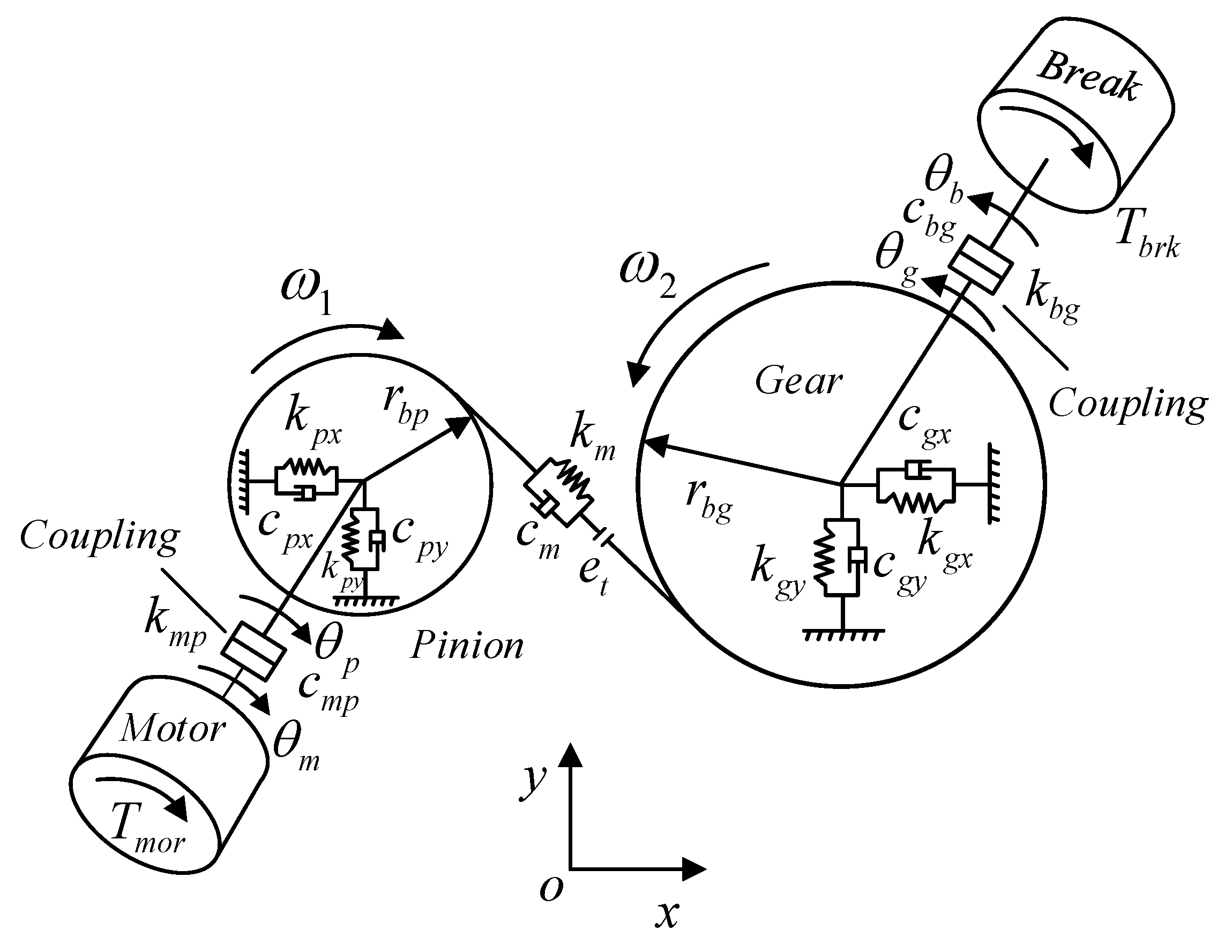
The dynamic model is to obtain the dynamic responses to be input to the wear model. In this section, an 8 DOFs tribo-dynamic model of spur gear system is developed by incorporating TVMS, time-varying load sharing, dynamic friction coefficient; see Figure 1.
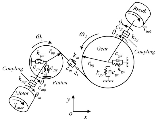
Figure 1.
Diagram of the gear dynamic model.
The equations of motion used to describe the coupled torsional and translational models can be formulated as:
Herein, , , , and refer to the rotational displacements of the pinion, gear, load, and motor, respectively; and , and , indicate the vibration displacements of the pinion and gear, respectively. and donate the masses of the pinion and gear correspondingly. Likewise, the inertias of the pinion and the gear are expressed as and , respectively.
The major parameters contained in the model are given in Table 1. The contact force is modelled by gear meshing stiffness , meshing damping and geometric transmission error (GTE), see Equation (2).
where and represents the base circle radius of the pinion and gear, indicates the pressure angle.

Table 1.
Parameters of the gear system.
The total frictional torques, namely and , can be given as
where , (i = 1, 2) denote the radii of curvature at the contact points, and can be expressed as
where i represents the ith gear tooth; L denotes the length of the line of action (LOA), computed as . Therefore, the instantaneous tooth surface velocities and can be expressed as
Herein, and represent the rotational speeds of the pinion and gear, respectively. The relative velocity = will be used to calculate the sliding distance for wear model and determine the direction of friction force. When , is negative; conversely, when , is positive with , . The friction force between the meshing teeth can be calculated by:
where and denote the load sharing ratio (LSR) and dynamic friction coefficient, respectively. To compute the load distribution between the meshing teeth pairs, we used a load distribution model proposed by Pedrero [24]. The detailed descriptions can be referred to reference [24].
where , , and denotes the contact ratio.
The friction model proposed by Xu et al. [25] is applied to obtain the dynamic friction coefficient. This model is on the basis of regression of experimental tests under a wide range of operating conditions and has been demonstrated by both simulated and experimental data. The dynamic friction coefficient is given as
where
and where is Hertzian contact pressure, and , , donates slide to roll ratio, entrainment velocity, and the inlet oil viscosity, respectively. is the RMS composite surface roughness, and to are regression coefficients, with .
In this study, the potential energy method, which includes the bending, shear, axial compressive, and Hertzian contact energies along with the fillet foundation deflection was adopted to estimate the meshing stiffness [26]. According to the potential energy method, the bending, shear, and axial compressive potential energies stored in the meshing teeth can be calculated by [27]:
where F denotes the gear contact force, and , , and are the bending, shear, and axial compressive stiffnesses, respectively. Based on the results derived by Yang and Sun [28], the Hertzian contact stiffness for gear pairs can be linearized to a constant and determined using the tooth width Wand material properties, namely the Poisson’s ratio (ν) and elastic modulus (E).
With Hertzian, bending, shear and axial compressive stiffness, the gear mesh stiffness for one tooth pair can be obtain by using [25]:
where donates the pinion and gear, respectively. For two pairs of meshing gears, the total effective mesh stiffness can be calculated as
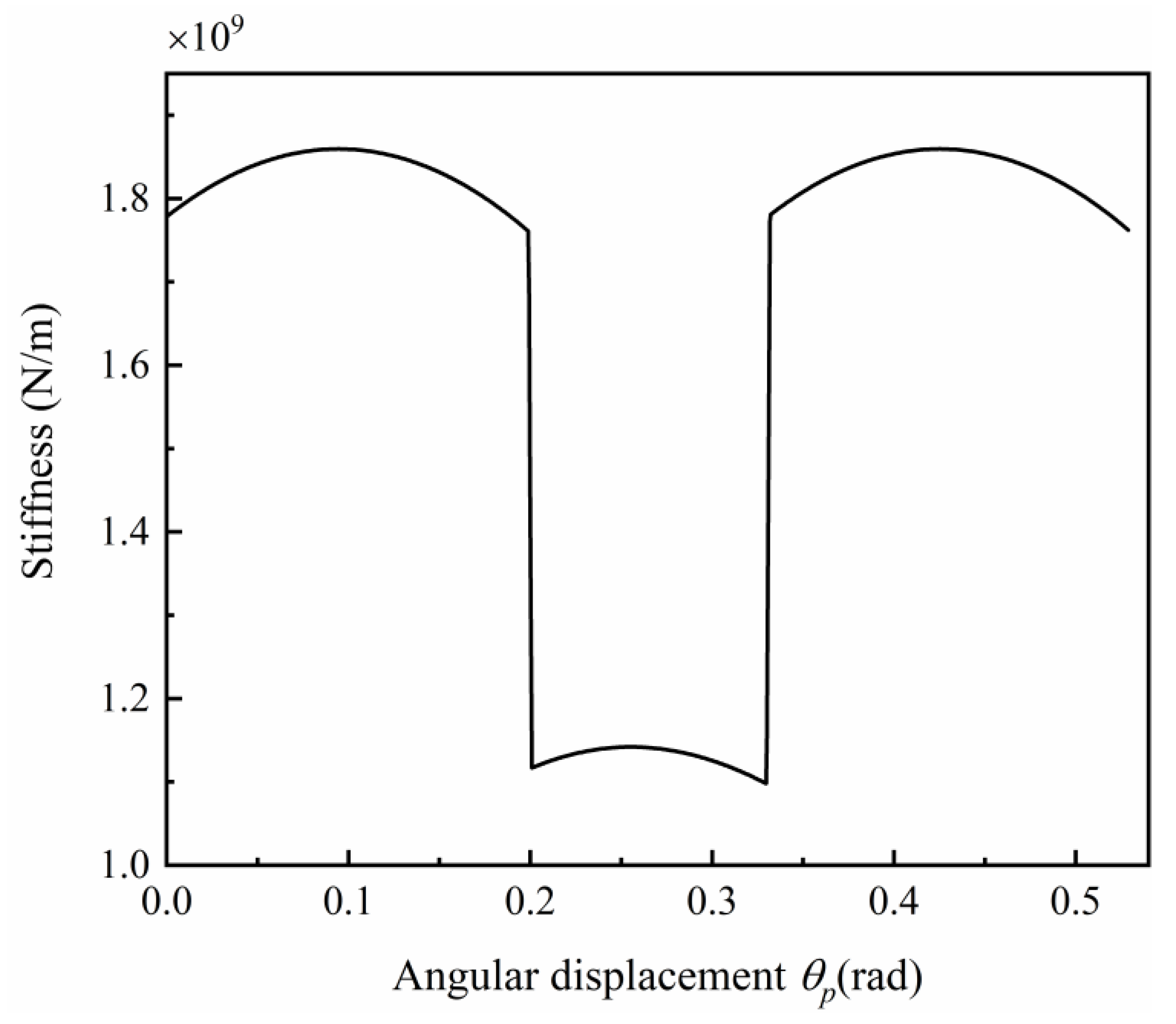
where denote the first and second meshing teeth pair, respectively. The mesh stiffness with angular displacement is demonstrated in Figure 2.
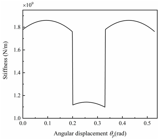
Figure 2.
Time-varying mesh stiffness (TVMS) with angular displacement.
On account of the gear wear induced tooth profile change h is in micron level, the wear induced meshing stiffness change is around in the level [29], while the meshing stiffness is around in the level correspondingly. Therefore, the stiffness change can be neglected compared with the value of meshing stiffness.
3. Dynamic Wear Prediction Model
In this section, an improved dynamic wear prediction model for spur gear system is proposed. The well-known Archard wear equation [30], which is one of the earliest wear laws, is used in this work. The Archard wear model is the most commonly applied in gear wear, because it takes into account the contact pressure, sliding condition and material properties of gear contact surface. The Archard’s wear equation is generally expressed as:
where stands for the wear depth, is a dimensionless wear coefficient, is the sliding distance, and is the hertzian contact pressure between the mating point on the mating gear. The contact pressure can be calculated as:
where denotes the gear width, denotes elastic modulus, and represents the equivalent radius of curvature. Consequently, the predicted wear depth accumulated on the pinion and gear can be expressed:
Herein, represent the accumulated wear depth after the certain cycle n of each meshing points on the pinion and gear. However, it is almost impossible that the values of wear depths are updated after each loading cycle with the evolution of gear surface conditions. Therefore, a modified method shown below is used to improve the computational efficiency and guarantee the calculation precision.
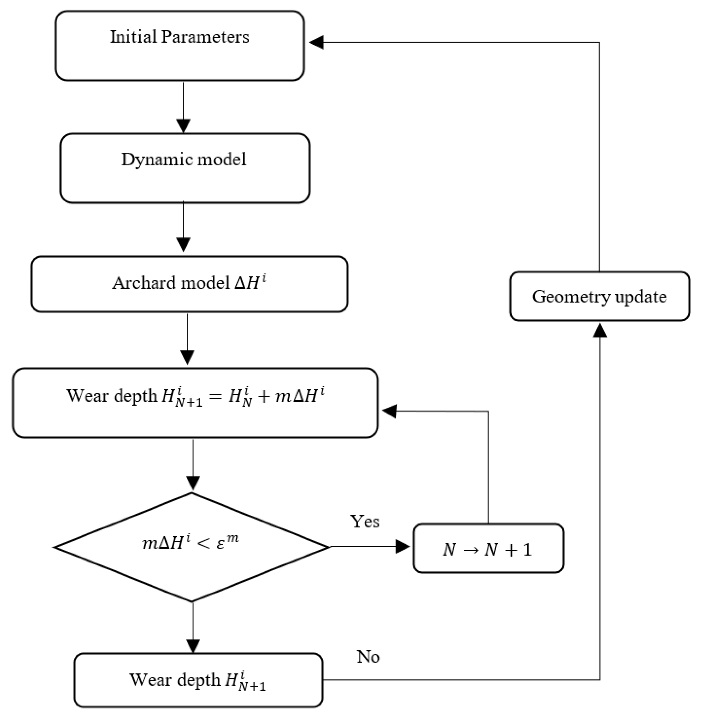
According to Equation (14), the wear depth after one wear cycle can be determined using sliding distance , dynamic contact pressure and wear coefficient [12,31]. The wear depth of each contact point are assumed to remind the same during experiencing a fixed wear cycle m. When the maximum accumulated wear depth of any point on the mating surface during the fixed wear cycle m meets a predetermined wear threshold , the gear surface needs to be renewed in order to update contact pressure by performing another dynamic analysis of gear system. The total cumulative wear depth of every point on the surface is obtained by summing up wear depths of every point for all processes with different pressure updates. Figure 3 demonstrates the flowchart of the dynamic wear prediction model.
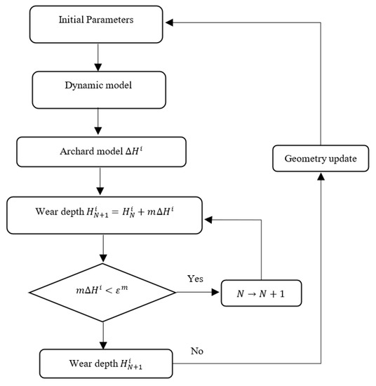
Figure 3.
Whole procedure of the dynamic wear prediction model.
4. Numerical Results and Discussion
In this section, with the dynamic gear model and wear prediction method introduced in Section 3, the coupling effects between the gear surface wear and the gear dynamic characteristics will be investigated. GTE is the geometric deviation from perfect gear, and it can be used to represent gear surface wear in subsequent analysis. With valid evaluated meshing stiffness and GTE, the gear mesh force can be calculated by Equation (2), then the wear induced gear dynamic responses and vibrations can be achieved through the proposed dynamic model. Table 2 lists the basic parameters of the spur gear pair and dynamic simulation.
Table 2.
Parameters of the spur gear transmission involved in the dynamic simulation.
4.1. Effects of Gear Surface Wear on the Dynamic Response
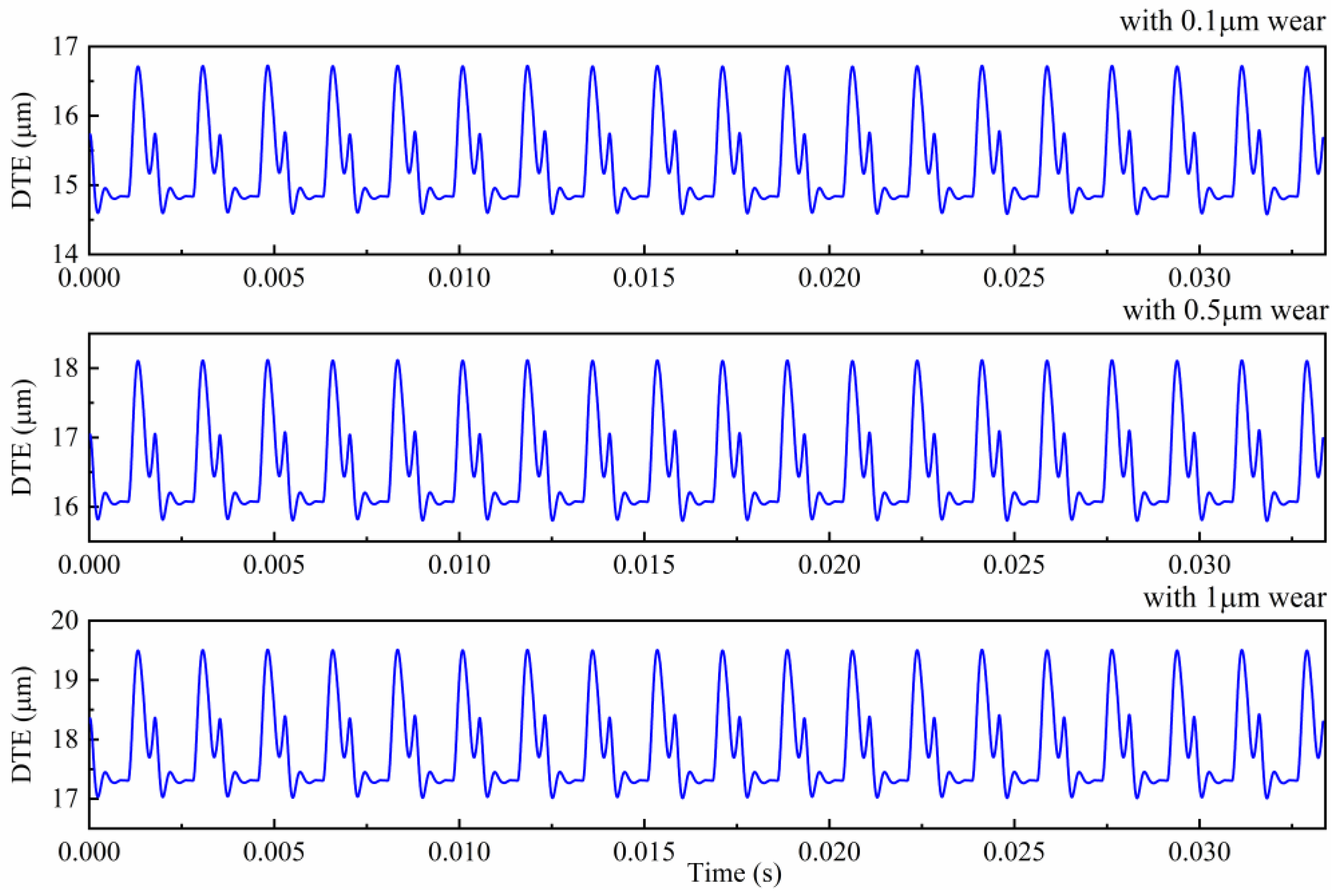
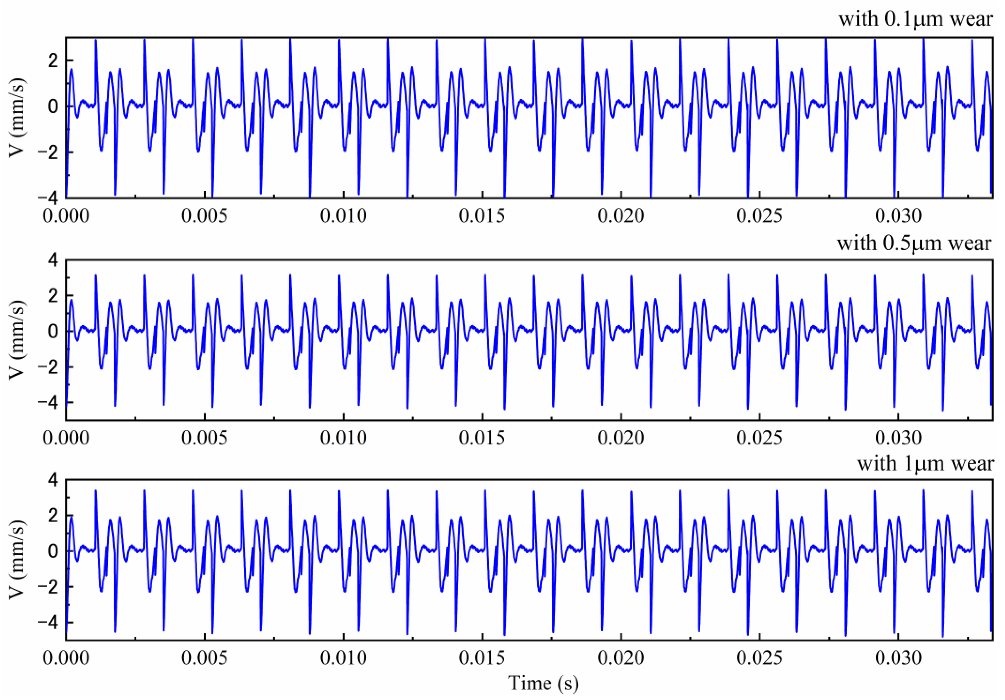
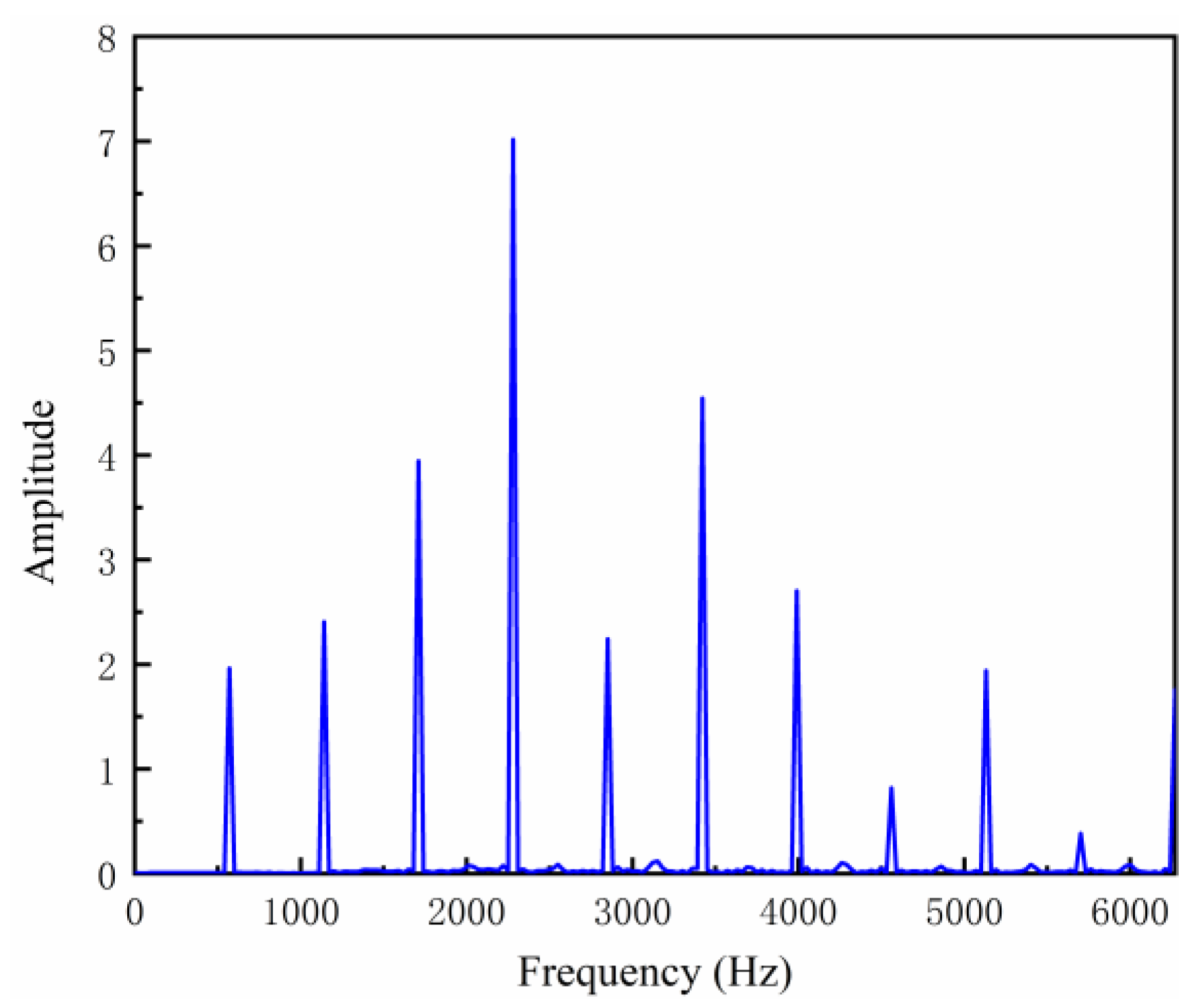
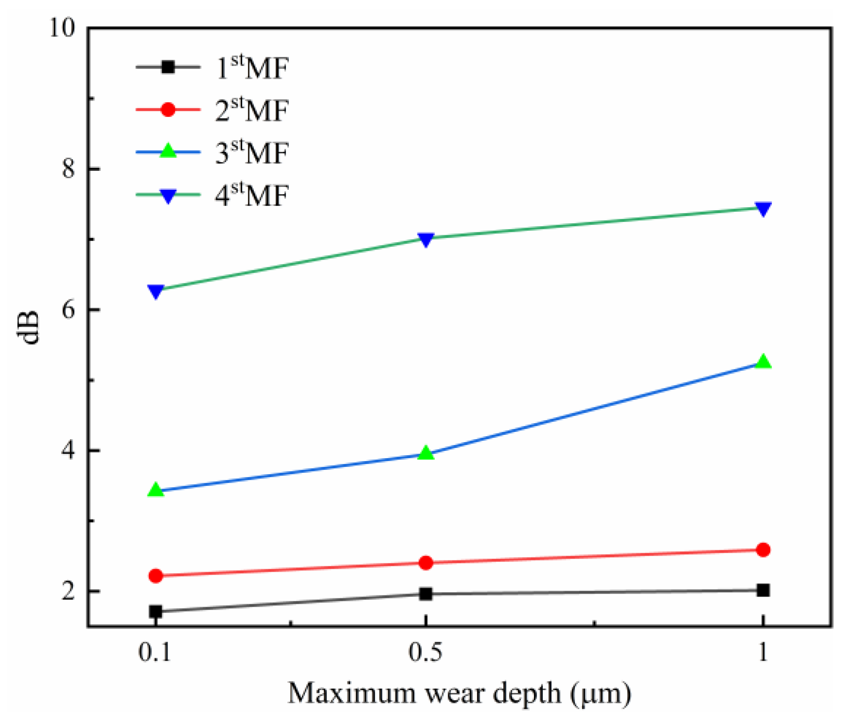
In this case, the rotational speed of input shaft is set as 30 Hz and the torque of brake is set as 60. For comparing convenience, gear maximum wear depth with 0.1 , 0.5 , and 1 are considered in this study. Gear surface wear was found to affect the dynamic signals of the gearbox, which resulting in higher transmission error and then higher vibration and noise, as shown in Figure 4. With respect to the dynamic transmission error, the maximum values are , and . Figure 5 depicts the vertical velocity of a pinion at difference wear levels. Correspondingly, the root-mean-square (RMS) value of is with wear, then increases to with wear and reaches to with wear. Therefore, gear surface wear serves as one kind of geometric deviation, which can increase transmission error of the gear system resulting in higher vibration. In addition, Figure 6 illustrates frequency spectrum of with 0.5 μm wear, and the change trends of first four meshing frequency (MF) amplitudes under different wear severities are plotted in Figure 7. It is observed that the amplitudes of MF will increase alone with gear wear process. Therefore, spectrum can be used for monitoring gear wear process.
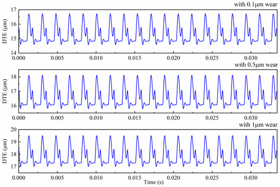
Figure 4.
Dynamic transmission error (DTE) with different wear severities.
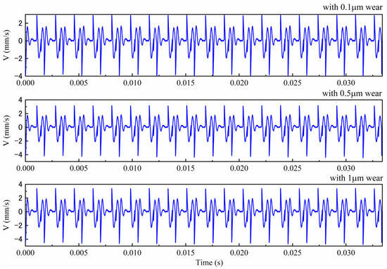
Figure 5.
Vibrations of casing under different wear severities.
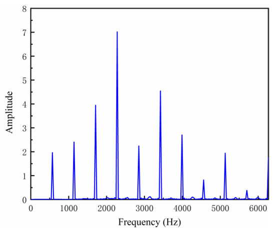
Figure 6.
Frequency spectrum of with 0.5 wear.
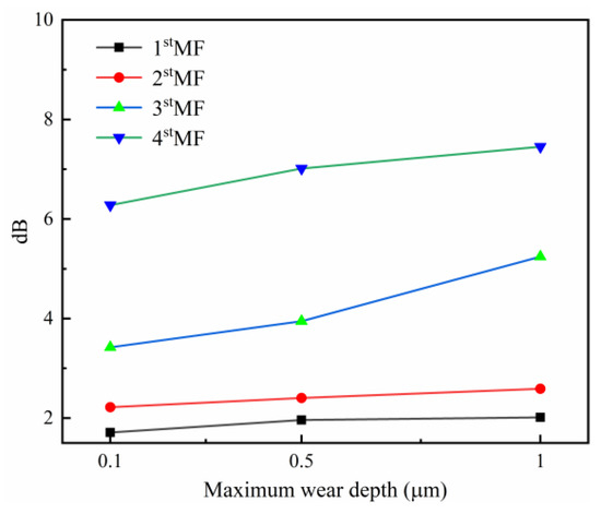
Figure 7.
Spectral amplitudes of the first four meshing frequencies (MFs) alone with wear process.
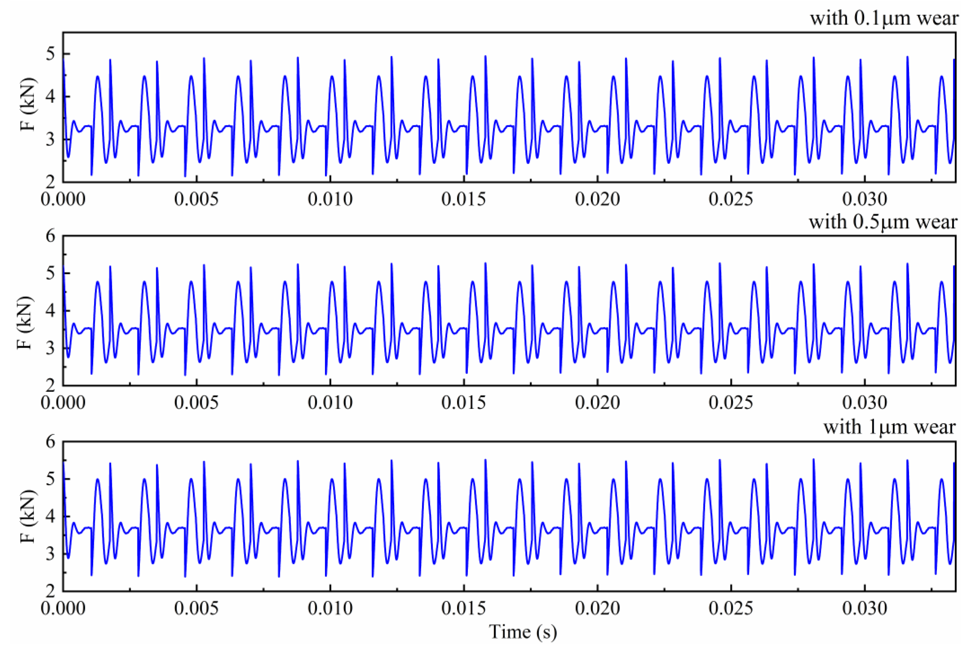
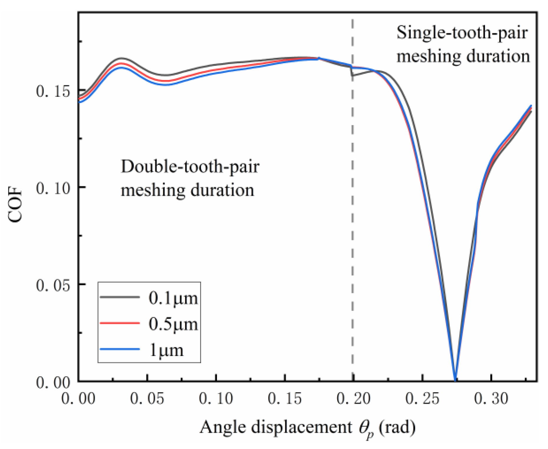
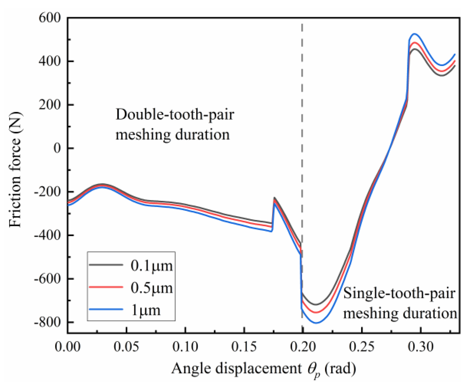
The predicted gear meshing force under different wear severities are displayed in Figure 8. As demonstrated in Figure 8, the meshing fore with wear has higher fluctuation than those with and wear. The mean values of mesh force are calculated, which are , and under different wear severities. Therefore, gear wear increases the magnitude of gear meshing force. According to Equation (2), the increase in GTE caused by tooth surface wear inevitably enhance the dynamic meshing force. Apart from that, friction is a crucial source of gear vibrations. The change in friction during the wear process also affects the meshing force. Figure 9 and Figure 10 demonstrate the evolution of coefficient of friction (COF) and friction force with wear process. It should be pointed out that, for clarity, Figure 9 and Figure 10 only tracked the COF and friction force between the first mating pair which initially mesh at gear tooth root. As shown in Figure 9, the COF decreases slightly with running-in wear, mainly because of the reduction in surface roughness value. J. Jamari et al. [18] found that this reduction in roughness still exist even after running-in wear, and becomes higher as running-in time. Therefore, in this simulation, the initial RMS composite surface roughness is set as , and it changes to with wear and with wear. The results depicted in Figure 9 reveal that the COF is sensitive to the change in roughness magnitude during the running-in wear process. However, the friction force increases as shown in Figure 10 because of the improved dynamic meshing force, especially during the single-tooth-pair meshing duration. Based on Equation (1), the increasing friction force leads to the increase in dynamic responses and meshing force, and it is believed that the effect of friction will become more and more significant as the wear depth increases.
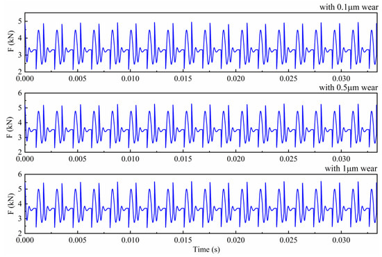
Figure 8.
Gear mesh force of gear system under different wear severities.

Figure 9.
Friction coefficient under different wear severities.
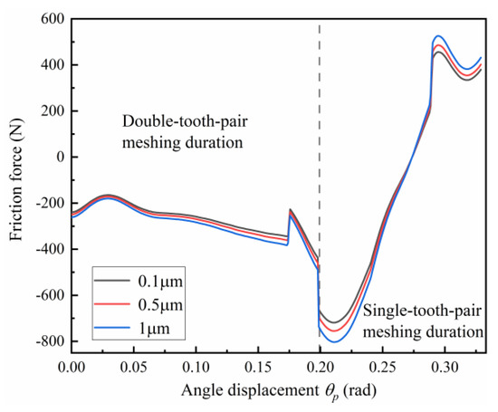
Figure 10.
Friction force under different wear severities.
4.2. Effects of the Dynamic Response on Gear Surface Wear
To better understand the impact of gear dynamics on gear surface wear, the wear behaviors under quasi-static conditions are taken as a baseline for comparisons. In this case, the gear system is operating at a rotational speed of 30 Hz, while the torque of the brake remains as 60 . In addition, the wear coefficient is set as , and the fixed wear cycle m is set as . During this period, the maximum accumulated wear depth at any point on the meshing surface reaches the predetermined wear threshold , the geometry of gear surface needs to be reconstituted. Then, the updated gear surfaces are fed into the dynamic model to renew the dynamic meshing force.
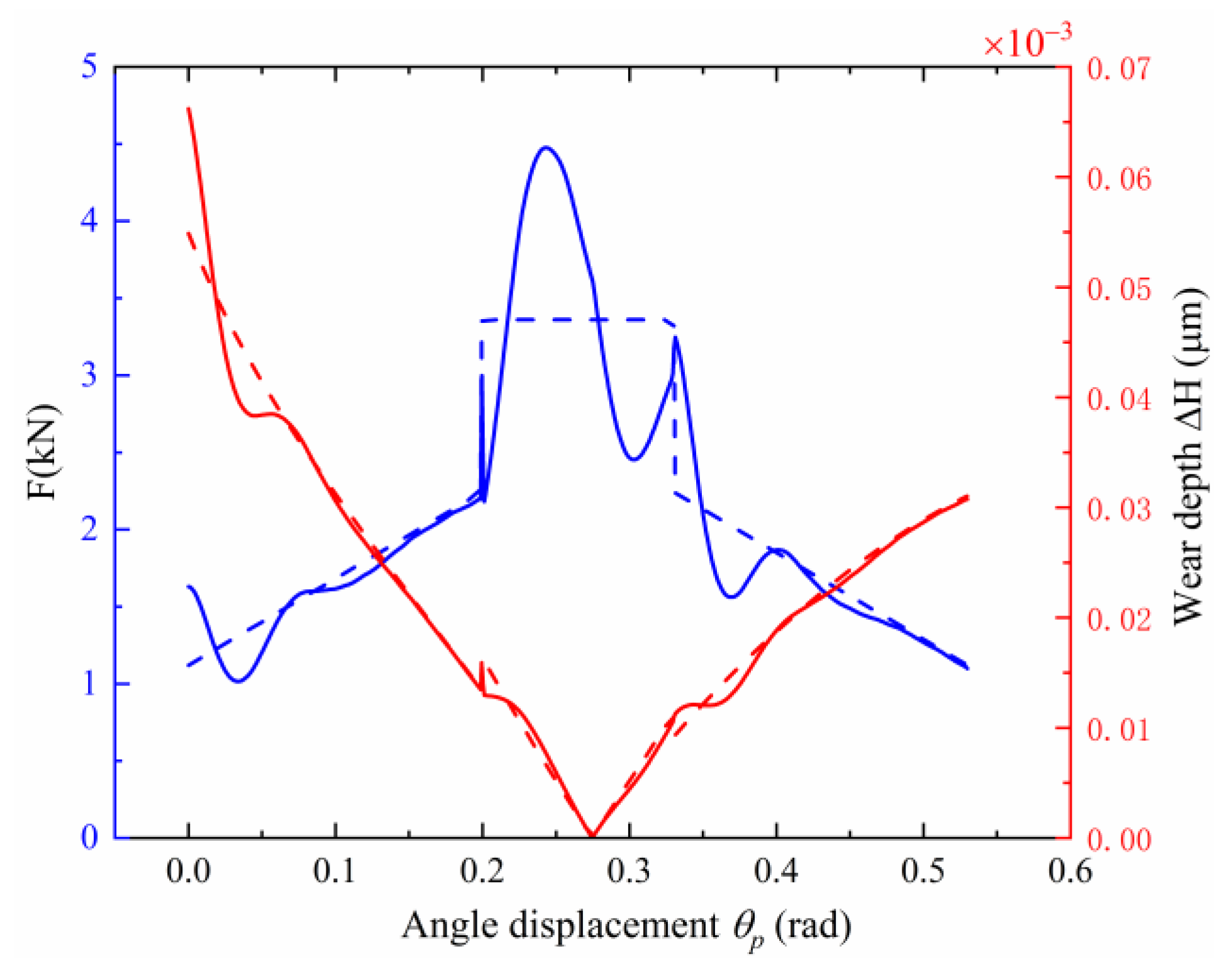
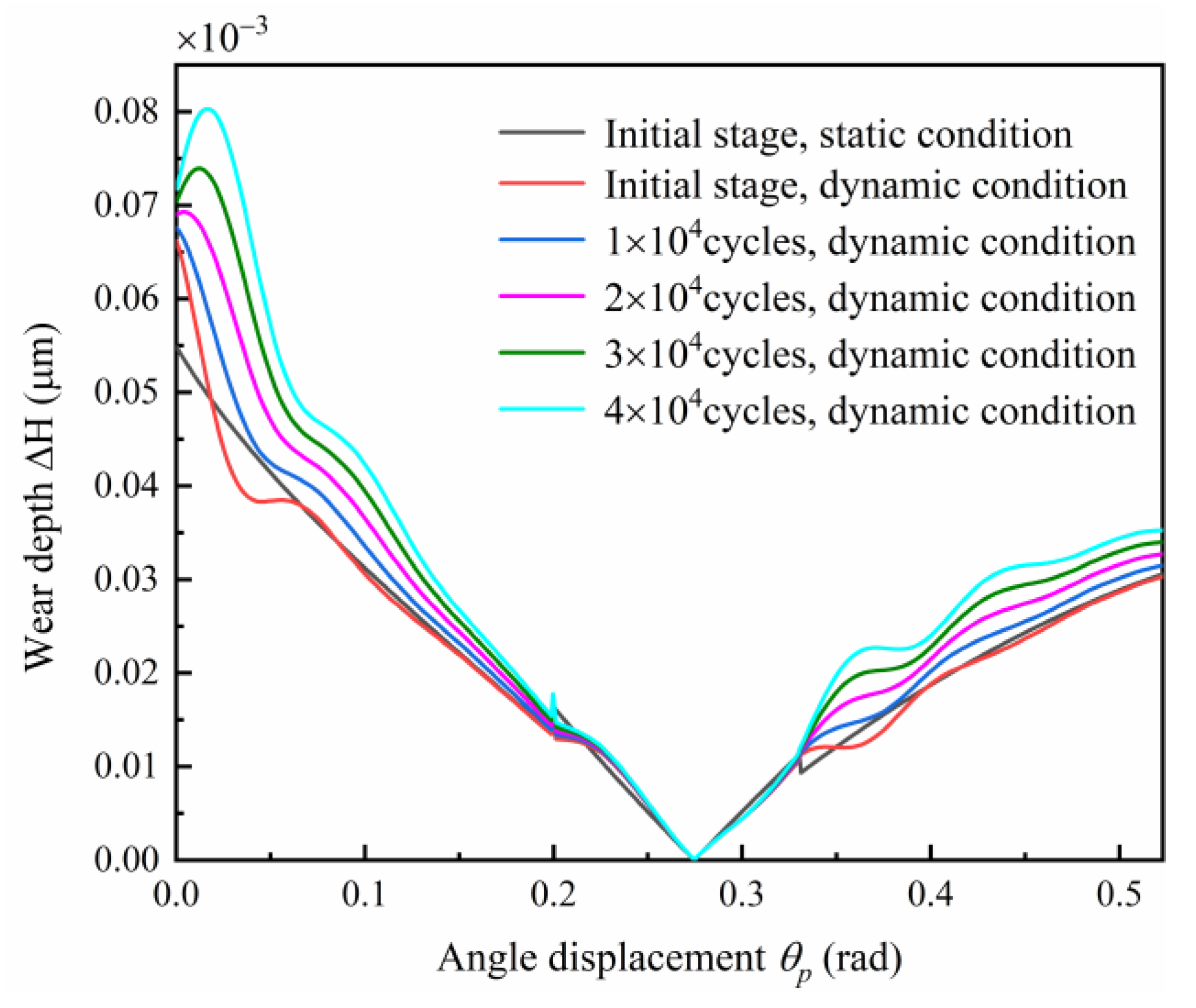
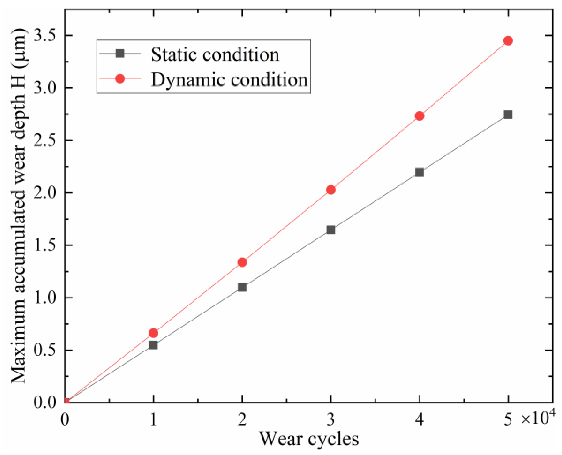
The comparisons of meshing force and wear depth distribution under static and dynamic conditions are illustrated in Figure 11. From Figure 11, it can be seen that the wear depth under dynamic conditions and static conditions are quite approximate in the initial stage. However, the wear depth under dynamic conditions become higher compared with static conditions with the wear process, as demonstrated in Figure 12. The reason is that dynamic contact force increases due to surface wear, as explained in Section 4.1, and the dynamic contact force is typically lager than the corresponding quasistatic force, ultimately, which results in a faster wear process. In consequence, the maximum accumulated wear depths under dynamic conditions exceed those under static conditions with the increase in wear cycle, as shown in Figure 13. Therefore, in order to guarantee accurate wear prediction results, the proposed dynamic wear prediction model is necessary.
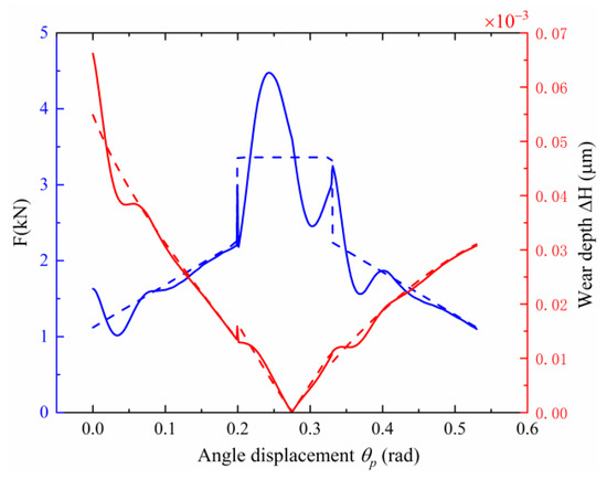
Figure 11.
The meshing force and wear depth distribution of a pinion under static and dynamic conditions in the initial stage. (Dotted lines donate the static condition, and solid lines donate the dynamic condition).
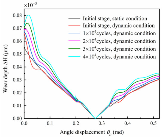
Figure 12.
Evolutions of wear depth distribution of a pinion with wear process.
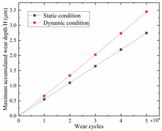
Figure 13.
Maximum accumulated wear depth of a pinion under different conditions.
The proposed model has exhibited its capability in wear prediction. However, it also has some drawbacks. For example, it cannot consider the change in micro hardness caused by wear. Additionally, the wear coefficient is assumed as a constant value. However, the wear coefficient is susceptible to surface conditions, such as micro hardness and roughness [8,32]. In the future, the gear-wear prediction methodology proposed by Ke Feng et al. [33] which updated Archard’s wear coefficient based on vibration responses will be applied to improve the present model. Moreover, though the proposed model has been verified through simulation analysis in this paper, experimental validations are lacking. In the future, the experiments under dry and lubricated conditions will be arranged to verify the proposed model.
5. Conclusions
In this paper, a dynamic model, which integrates TVMS, friction, and time-varying load-sharing ratio, is established, and then combine with the Archard wear model to establish a dynamic wear prediction model. An improved updated method of wear depth is proposed. With help of the proposed dynamic wear prediction model, the coupling effects between gear dynamic behaviors and gear surface wear process can be studied. Surface wear of a gear system results in the increase in dynamic responses, such as DTE, velocity, and meshing force. In turn, the increased meshing force results in faster wear process. Moreover, during the initial wear, the COF decrease slightly due to the reduction in surface roughness, but the friction force increases because of the improvement of dynamic meshing force. The ability of the proposed model in tracking and predicting wear process is superior to the classical static wear prediction model. Compared to the static prediction model, the proposed dynamic prediction model can update the wear depth distribution with wear process. Although the wear depth distributions under dynamic and static conditions are quite approximate in the initial stage, the maximum wear depth of a pinion under dynamic conditions already reaches 1.6 times that of the corresponding quasi-static condition. Therefore, the proposed dynamic wear prediction model is more reasonable for predicting the wear process.
Author Contributions
Conceptualization, J.R. and H.Y.; methodology, H.Y.; software, J.R.; validation, J.R. and H.Y.; formal analysis, J.R.; investigation, J.R.; resources, H.Y.; data curation, H.Y.; writing—original draft preparation, J.R.; writing—review and editing, J.R.; supervision, H.Y.; project administration, H.Y. All authors have read and agreed to the published version of the manuscript.
Funding
This research was funded by National Science and Technology Major Project of the Ministry of Science and Technology of China, grant number J2019-IV-0016-0084.
Institutional Review Board Statement
Not applicable.
Informed Consent Statement
Not applicable.
Data Availability Statement
Not applicable.
Conflicts of Interest
The authors declare no conflict of interest.
References
- Fernandes, P.; McDuling, C. Surface contact fatigue failures in gears. Eng. Fail. Anal. 1997, 4, 99–107. [Google Scholar] [CrossRef]
- Wojnarowski, J.; Onishchenko, V. Tooth wear effects on spur gear dynamics. Mech. Mach. Theory 2003, 38, 161–178. [Google Scholar] [CrossRef]
- Osman, T.; Velex, P. Static and dynamic simulations of mild abrasive wear in wide-Faced solid spur and helical gears. Mech. Mach. Theory 2010, 45, 911–924. [Google Scholar] [CrossRef]
- Jamari, J.; Ammarullah, M.I.; Santoso, G.; Sugiharto, S.; Supriyono, T.; van der Heide, E. In Silico Contact Pressure of Metal-On-Metal Total Hip Implant with Different Materials Subjected to Gait Loading. Metals 2022, 12, 1241. [Google Scholar] [CrossRef]
- Choy, F.; Polyshchuk, V.; Zakrajsek, J.; Handschuh, R.; Townsend, D. Analysis of the effects of surface pitting and wear on the vibration of a gear transmission system. Tribol. Int. 1996, 29, 77–83. [Google Scholar] [CrossRef]
- Kuang, J.H.; Lin, A.D. The effect of tooth wear on the vibration spectrum of a spur gear pair. J. Vib. Acoust. 2001, 123, 311–317. [Google Scholar] [CrossRef]
- Yesilyurt, I.; Gu, F.; Ball, A.D. Gear tooth stiffness reduction measurement using modal analysis and its use in wear fault severity assessment of spur gears. NDT E Int. 2003, 36, 357–372. [Google Scholar] [CrossRef]
- Yuksel, C.; Kahraman, A. Dynamic tooth loads of planetary gear sets having tooth profile wear. Mech. Mach. Theory 2004, 39, 695–715. [Google Scholar] [CrossRef]
- Ding, H.; Kahraman, A. Interactions between nonlinear spur gear dynamics and surface wear. J. Sound Vib. 2007, 307, 662–679. [Google Scholar] [CrossRef]
- Kahraman, A.; Ding, H. A Methodology to Predict Surface Wear of Planetary Gears Under Dynamic Conditions. Mech. Based Des. Struct. Mach. 2010, 38, 493–515. [Google Scholar] [CrossRef]
- Liu, X.; Yang, Y.; Zhang, J. Investigation on coupling effects between surface wear and dynamics in a spur gear system. Tribol. Int. 2016, 101, 383–394. [Google Scholar] [CrossRef]
- Flodin, A.; Andersson, S. Simulation of mild wear in spur gears. Wear 1997, 207, 16–23. [Google Scholar] [CrossRef]
- Bajpai, P.; Kahraman, A.; Anderson, N.E. A Surface Wear Prediction Methodology for Parallel-Axis Gear Pairs. J. Tribol. 2004, 126, 597–605. [Google Scholar] [CrossRef]
- Masjedi, M.; Khonsari, M. On the prediction of steady-State wear rate in spur gears. Wear 2015, 342, 234–243. [Google Scholar] [CrossRef]
- Feng, K.; Borghesani, P.; Smith, W.A.; Randall, R.B.; Chin, Z.Y.; Ren, J.; Peng, Z. Vibration-Based updating of wear prediction for spur gears. Wear 2019, 426, 1410–1415. [Google Scholar] [CrossRef]
- Feng, K.; Ji, J.; Ni, Q.; Beer, M. A review of vibration-Based gear wear monitoring and prediction techniques. Mech. Syst. Signal Process. 2023, 182, 109605. [Google Scholar] [CrossRef]
- Mark, W.D. Performance-Based Gear Metrology: Kinematic-Transmission-Error Computation and Diagnosis; John Wiley & Sons: Hoboken, NJ, USA, 2012. [Google Scholar]
- Jamari, J.; Ammarullah, M.; Afif, I.; Ismail, R.; Tauviqirrahman, M.; Bayuseno, A. Running-In Analysis of Transmission Gear. Tribol. Ind. 2021, 43, 434–441. [Google Scholar] [CrossRef]
- He, S.; Gunda, R.; Singh, R. Effect of sliding friction on the dynamics of spur gear pair with realistic time-Varying stiffness. J. Sound Vib. 2007, 301, 927–949. [Google Scholar] [CrossRef]
- Chen, S.; Tang, J.; Luo, C.; Wang, Q. Nonlinear dynamic characteristics of geared rotor bearing systems with dynamic backlash and friction. Mech. Mach. Theory 2011, 46, 466–478. [Google Scholar] [CrossRef]
- Jiang, H.; Shao, Y.; Mechefske, C.K. Dynamic characteristics of helical gears under sliding friction with spalling defect. Eng. Fail. Anal. 2014, 39, 92–107. [Google Scholar] [CrossRef]
- Luo, Y.; Baddour, N.; Liang, M. Dynamical modeling and experimental validation for tooth pitting and spalling in spur gears. Mech. Syst. Signal Process. 2018, 119, 155–181. [Google Scholar] [CrossRef]
- Liu, P.; Zhu, L.; Gou, X.; Shi, J.; Jin, G. Modeling and analyzing of nonlinear dynamics for spur gear pair with pitch deviation under multi-State meshing. Mech. Mach. Theory 2021, 163, 104378. [Google Scholar] [CrossRef]
- Pedrero, J.I.; Pleguezuelos, M.; Artés, M.; Antona, J.A. Load distribution model along the line of contact for involute external gears. Mech. Mach. Theory 2010, 45, 780–794. [Google Scholar] [CrossRef]
- Xu, H.; Kahraman, A.; Anderson, N.E.; Maddock, D.G. Prediction of Mechanical Efficiency of Parallel-Axis Gear Pairs. J. Mech. Des. 2006, 129, 58–68. [Google Scholar] [CrossRef]
- Liang, X.; Zuo, M.J.; Pandey, M. Analytically evaluating the influence of crack on the mesh stiffness of a planetary gear set. Mech. Mach. Theory 2014, 76, 20–38. [Google Scholar] [CrossRef]
- Yang, D.C.H.; Lin, J.Y. Hertzian Damping, Tooth Friction and Bending Elasticity in Gear Impact Dynamics. J. Mech. Transm. Autom. Des. 1987, 109, 189–196. [Google Scholar] [CrossRef]
- Yang, D.C.H.; Sun, Z.S. A Rotary Model for Spur Gear Dynamics. J. Mech. Transm. Autom. Des. 1985, 107, 529–535. [Google Scholar] [CrossRef]
- Yu, W. Dynamic Modelling of Gear Transmission Systems with and without Localized Tooth Defects. Ph.D. Thesis, Queen’s University, Kingston, ON, Canada, 2017. [Google Scholar]
- Archard, J.F. Contact and Rubbing of Flat Surfaces. J. Appl. Phys. 1953, 24, 981–988. [Google Scholar] [CrossRef]
- Brauer, J.; Andersson, S. Simulation of wear in gears with flank interference—A mixed FE and analytical approach. Wear 2003, 254, 1216–1232. [Google Scholar] [CrossRef]
- Jamari, J.; Ammarullah, M.; Saad, A.; Syahrom, A.; Uddin, M.; van der Heide, E.; Basri, H. The Effect of Bottom Profile Dimples on the Femoral Head on Wear in Metal-On-Metal Total Hip Arthroplasty. J. Funct. Biomater. 2021, 12, 38. [Google Scholar] [CrossRef]
- Feng, K.; Smith, W.A.; Peng, Z. Use of an improved vibration-Based updating methodology for gear wear prediction. Eng. Fail. Anal. 2020, 120, 105066. [Google Scholar] [CrossRef]
Publisher’s Note: MDPI stays neutral with regard to jurisdictional claims in published maps and institutional affiliations. |
© 2022 by the authors. Licensee MDPI, Basel, Switzerland. This article is an open access article distributed under the terms and conditions of the Creative Commons Attribution (CC BY) license (https://creativecommons.org/licenses/by/4.0/).