Article

Microstructure, Mechanical and Corrosion Properties of Column-Free CrNx Coatings Deposited by Closed Field Unbalanced Magnetron Sputtering

1
School of Materials Science and Engineering, Xi’an University of Technology, Xi’an 710048, China
2
Third Research Department, Shanghai Academy of Spaceflight Technology, Shanghai 201109, China
*
Author to whom correspondence should be addressed.
Coatings 2022, 12(9), 1327; https://doi.org/10.3390/coatings12091327
Submission received: 26 July 2022 / Revised: 3 September 2022 / Accepted: 7 September 2022 / Published: 12 September 2022

Abstract

:
CrNx coatings with a low nitrogen content below 31.7 at.% were deposited using closed field unbalanced magnetron sputtering by varying the N2:Ar flow ratio. A dense and column-free CrNx coating was obtained at a nitrogen content of 14.8 at.%, whereas the other CrNx coating were all columnar structured. The column-free CrNx coating was composed of two types of structures: an N-incorporated Cr(N) solid solution matrix with a high number of point defects and a Cr(N) matrix with dispersed Cr2N nanocrystallines. The pinning effect of Cr2N nanocrystallines and point defects in Cr(N) grains are responsible for the formation of a column-free CrNx coating. The columnar-free CrNx coating exhibits a high hardness of 33.7 GPa, which is comparable to the hardness of Cr2N coating but 2.6 times larger than that of the Cr coating. It also has significantly better corrosion resistance than both Cr and Cr2N coating, with a corrosion current density of 4.1 × 1.0−9 A/cm2 that was only 1/20 than that of Cr coating.

1. Introduction

Chromium nitride (CrN) coatings deposited by magnetron sputtering have been widely studied as a potential protective coating for cutting tools, dies, friction parts, etc. because of their high hardness, good wear properties and corrosion resistance [1,2,3,4,5,6,7,8,9,10,11]. The CrNx coatings deposited by conversational direct current magnetron sputtering (DCMS) generally exhibit a loose columnar structure with porosity between the columnar grains [6,7,8,9,10]. This kind of structure can not only reduce the mechanical properties due to it’s low density but also speed up the pitting corrosion of metal substrates since corrosive media can easily diffuse though the porosity between the columnar grains to the substrates [9,10,11]. Therefore, fabricating dense and column-free CrNx coatings is an essential research topic for improving the properties of CrNx coatings.
Since the loose columnar structure of MS-deposited coatings is mostly caused by the low ion density of DCMS [12], numerous efforts [13,14,15,16,17,18,19,20,21,22] have been made to densify CrNx coatings by increasing ion energy and ion flux during deposition. When compared to CrNx coating deposited using conversional (balanced) magnetron sputtering, those deposited using unbalanced magnetron sputtering (UBMS) exhibit a denser compact-columnar structure [13,14]. With the use of modulated pulsed direct current power, closed-field unbalanced magnetron sputtering (CFUBMS) can produce dense and equiaxially structured CrNx coatings [9]. In comparison, an CFUBMS using a modulated pulse power (MPP) can deposit denser columnar CrNx coating with finer grain size [15,16,17]. By using a high-power pulsed magnetron sputtering (HIPIMS) method, column-free CrNx coatings can be obtained [18,19,20,21,22]. The ion current density of Ar+ in CFUBMS was many times higher than that in UBMS and dozens of times higher than that in balanced magnetron sputtering when using direct current power [23]. Compared to DCMS, HIPIMS significantly increased the ion current density of Cr+ and Cr2+, with values dozens of times higher than those of Ar+ [19,21]. In general, the increased ion current density can enhance ion bombardment during coating growth, which in turn increases the mobility of adatoms, thereby sealing the porosity between the columnar grain boundaries and increasing the nucleation sites to form finer grain size. Additionally, these HIPIMS-deposited column-free CrNx coating was generally composed of a mixture of Cr + Cr2N or Cr2N + CrN phase. This indicates that the phase structure also has a significant impact on the formation of column-free structures, which is currently poorly understood and merits further research.
Therefore, a series of CrNx coating were fabricated at a low N2:Ar flow ratio in this work to create CrNx coatings with a mixture of Cr + Cr2N phase. Instead of HIPIMS, CFUBMS with direct current power were utilized to deposit the coatings to reduce the impact of energetic ions on the coating’s growth. The microstructure, mechanical and corrosion properties of these CrNx coatings were investigated, and the formation mechanism of column-free CrNx coatings was explained.

2. Experimental Details

CrNx coatings were deposited on silicon wafers and AISI 304 stainless steel substrates using an CFUBMS system. This CFUBMS system contains four rectangular unbalanced magnetrons evenly distributed around a cylinder chamber with a diameter of 450 mm. Two chromium targets (99.9% in purity, 330 mm × 133 mm in sizes) were placed in positions opposite each other. After the substrates were ultrasonically cleaned in acetone, they were laid on the sample holders. The distance of the target to the substrates was 120 mm. Prior to deposition, the chamber was first evacuated to a pressure of 3 × 10⁻³ Pa, and the substrates were then ion-cleaned for 15 min at a bias voltage of −400 V to remove the surface contaminates. Thereafter, the CrNx coatings were deposited using a direct current power supply in a N2/Ar mixed atmosphere. The N2:Ar flow ratios used to obtain CrNx coatings with different N contents are listed in Table 1. Considering that fewer adatoms are deposited on the coating surface, higher mobility of these adatoms will be obtained from ion bombardment in a CFUBMS under constant bias voltage during coating growth. A relatively low target current of 1.3 A, corresponding to a target power of 550 W, was applied to each Cr target. During depositions, a bias voltage of −65 V was applied on the substrates, which is the optimized bias voltage used for the deposition of metal nitride coatings with balanced hardness and adhesion strength according to our previous studies. The rotation speed of the sample holder was set at 5 rounds per minute.
The crystal structure of CrNx coatings was analyzed by X-ray diffractometer (Shimadzu/XRD-7000S, Kyoto, Japan) using the grazing incident X-ray diffraction (GIXRD) mode at a 1-degree incident angle. The surface and cross-sectional morphology of the coatings were observed using a scanning electron microscope (JEOL/JSM-6700F, Tokyo, Japan). The chemical composition of the coatings was analyzed by energy dispersive X-ray spectroscopy (EDS, Oxford/Energy 350, Oxford, UK) attached to the SEM and presented in Table 1. The chemical structure of the as-deposited coatings was investigated by X-ray photoelectron spectroscopy (Shimadzu/Kratos AXIS Ultra, Kyoto, Japan) using 150 W Al Kα radiation (1486.6 eV). The sample surface was etched with an argon ion gun for 1 min before the test. The peak fittings were performed using a Gaussian–Lorentzian peak shape and Shirley-type background subtraction. The microstructure was also investigated using a transmission electron microscope (JEOL/JEM-3010, Tokyo, Japan). The hardness (H) and elastic modulus (E) of the coatings were evaluated using a nano-indenter (Agilent/Nano Indenter G200, Santa Rosa, CA, USA) equipped with a Berkovich diamond tip. The indentation depth was set at 120 nm, less than 1/10 of the coating thickness, to eliminate the influence of the substrate on the coating characteristics. The potentiodynamic polarization experiments were performed on the coating deposited on AISI 304 stainless steel substrates using a solartron electrochemical testing system in a 3.5 wt.% NaCl aqueous solution at room temperature. The potential scan rate is 0.5 mV/s and the stabilization duration of open circuit potential measurement is 600 s.

3. Results and Discussion

The chemical compositions of the as-deposited CrNx coatings are listed in Table 1. It shows that as the N2:Ar flow ratio increased from 0:15 to 6:15, the nitrogen content gradually increased from 0 to 31.7 at.%. Figure 1a shows the XRD patterns of CrNx coatings deposited at various N2:Ar flow ratios. The diffraction peaks showed at 44.4°, 64.5°, and 81.6° can be correlated to the (110), (200) and (211) peaks of the bcc Cr phase (JCPDS 06-0694). The Cr coating displayed a (110) preferred orientation. The CrNx coatings deposited at N2:Ar flow ratio below 2:15 generally exhibit a phase structure resembling the bcc Cr phase, but with a shifting of diffraction peaks to lower angles as a result of incorporation of N to Cr lattices generated a bcc Cr(N) solid solution phase. It was found that the full width at half maximum (FWHM) of these coatings also decreased gradually with the increase of N2:Ar flow ratio, indicating the formation of finer grain size. The CN-3 coating deposited at N2:Ar flow ratio of 3:15 exhibits a broadening diffraction peak ranging from 41.5° to 46.2°, which can be attributed to either an overlap peak of the (110) peak of the bcc Cr(N) phase and (111) peak of the hcp Cr2N phase (JCPDS 06-350803) or the formation of an amorphous phase. With a further increase of N2:Ar flow ratio above 4:15, the coatings were dominated by the hcp Cr2N phase, and a single Cr2N coating was obtained at N2:Ar flow ratio of 6:15. The XRD results show that the phases of CrNx coatings changed from single Cr to Cr(N), and then Cr(N) + Cr2N to single Cr2N with the increase of N2:Ar flow ratio. The average grain size of the as-deposited CrNx coatings was calculated based on the FWHM and diffraction angles measured from XRD patterns, as shown in Figure 1b. The average grain sizes of the coatings decreased from 17.3 to 4.5 nm as the N2:Ar flow ratio increased from 0:15 to 2:15. The average grain size of CN-3 and CN-4 coatings was similar to that of CN-2 coatings. With the further increase of N2:Ar flow ratio to 6:15, the average grain size of the CN-6 coating increased to 10.4 nm.
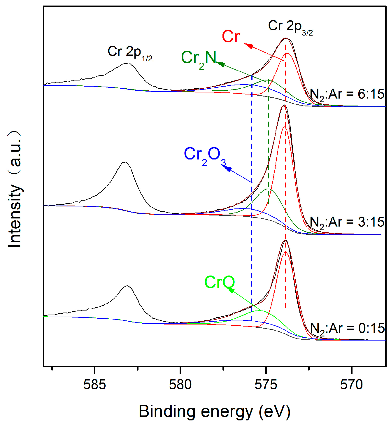
To further confirm the chemical states of the typical phase of as-deposited CrNx coatings, the Cr 2p XPS spectra of the CrNx coating deposited at N2:Ar flow ratios of 0:15, 3:15 and 6:15 were investigated and are shown in Figure 2. The CrNx coatings deposited at N2:Ar flow ratios of 0:15 and 6:15 corresponded to the Cr and Cr2N coating, respectively. The Cr 2p3/2 spectra of Cr coating were deconvoluted systematically to the chemical states corresponding to Cr (binding energy (BE) = 573.9 eV [24]), Cr2O3 (BE = 575.8 eV [25]) and CrO (BE = 575.3 eV [25]). In contrast, a peak associated with Cr2N (BE = 574.8 eV [24]), which was identical in Cr2N coating, was also discovered in the CN-3 coating in addition to the peaks of Cr and Cr2O3. In addition, the higher binding energy of Cr peaks in the CN-3 coating compared to Cr2N coating also suggests a difference in bonding structure between these two coatings.
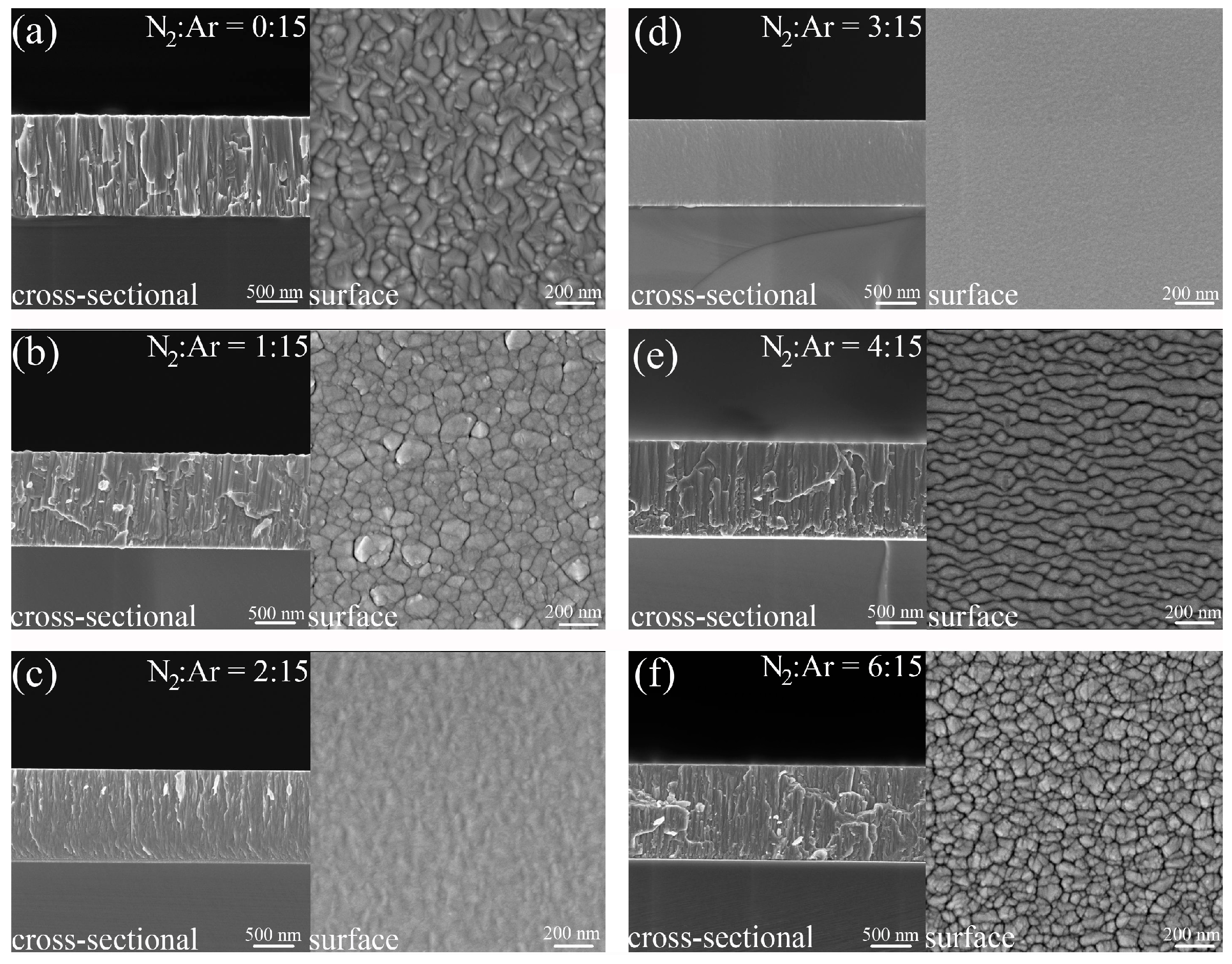
Figure 3 shows the surface and cross-sectional SEM micrographs of CrNx coating deposited at various N2:Ar flow ratios. It can be seen that except for the CN-3 coating, the other coatings all have dense columnar zone II structure according to the structure zone model for reactive sputtering deposited nitrides [26]. Since the dome-like structures in the surface micrographs are the tops of the columnar grains, the size of these domes corresponds to the diameter of the column grains obtained from the cross-sectional micrographs. The columnar grain size of both Cr and CN-1 coating was found to be similar and ranged from 80~200 nm. As the N2:Ar flow ratio increased to 2:15, the diameter of the columnar grains decreased dramatically. With the N2:Ar flow ratio further increased to 3:15, the CN-3 coating (Figure 3d) exhibited a super dense column-free cross-sectional and featureless surface structure. This type of structure can also be found in Greczynski’s research [21], in which the coating was deposited by HIPIMS at a bias voltage of −150 V. In comparison, the CN-4 coating has banding-like columnar grains, whereas the CN-6 coating has cylindrical columnar grains with a smaller diameter ranging from 30~80 nm.
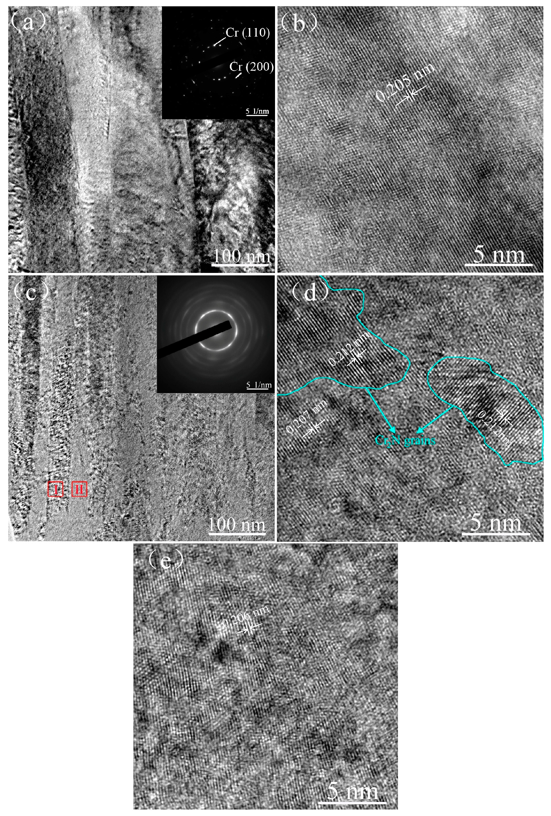
The microstructure of the column-free CrNx coating was further investigated using TEM. The TEM cross-sectional micrographs of the Cr and column-free CN-3 coatings are shown in Figure 4. Figure 4a shows that voids can be clearly observed between the boundaries of columnar grains in the Cr coating. The selected area electron diffraction (SAED) pattern of Cr coating was dotted-like rings, which is consistent with the relatively large grain size of the bcc Cr reflections. The HRTEM micrograph (Figure 4b) demonstrates that almost no dislocation or point defect can be identified in the Cr grains. In contrast, the column-free CN-3 coating exhibits a non-uniform structure with two distinct structures denoted as Structure I and Structure II in Figure 4c. The short rod-liked Structure I has a width of around 30~40 nm and a length of several hundred nanometers. The continuous SAED rings of the CN-3 coating indicated that the column-free coating was composed of finer grains. In the HRTEM micrograph of Structure I (Figure 4d), Cr2N nanocrystallines with a grain size of about 4~5 nm can be identified and dispersed in the Cr(N) matrix. Between the Cr2N nanocrystallines and the Cr(N) matrix, there were amorphous regions. Structure II (Figure 4e) mainly consisted of Cr(N) grains with numerous point defects. These results confirmed that the CN-3 coating was composed of a Cr(N) phase and Cr2N phase.
To explain the formation of a column-free structure, two factors must be considered: the pinning effect of Cr2N nanocrystallines and Cr(N) grains with numerous point defects. There were many Cr2N nanocrystallites were dispersed between the Cr(N) grains in the as-deposited column-free CrNx coatings. The Cr2N nanocrystallites have Cr-N covalent bonds with high bond strength and a different crystal structure compared to the Cr(N) matrix. This makes the Cr2N nanocrystallites act as second phase particles to inhibit the growth of Cr(N) grains. Furthermore, it was commonly found that when some of the normal grain growth is inhibited by second-phase particles, other grains with low surface energy can grow abnormally and form large columnar grains [27]. However, in this study, no abnormal growth can be observed in regions without Cr2N phase, which can be related to the fact that the point defects in Cr(N) grains hindered grain growth. The Cr2N phase began to be formed when the nitrogen concentration of the Cr-N system exceeded 16.1 at.% according to the phase diagram of Cr-N [28]. In this case, the Cr2N phase was formed at a lower nitrogen concentration of 14.8 at.%, which can be attributed to the relatively high ion current density of CFUBMS. The high density N+ can accelerate the N incorporation into Cr grains, forming the Cr(N) phase or Cr2N phase because of the smaller size and higher energy of N+ compared to N2. The Cr2N nanocrystallites can be formed at a much lower nitrogen content of just 5 at.% when HIPIMS with a high ion current of N+ and Cr+ were employed to deposit CrNx coating [21].
Figure 5 shows the hardness and elastic modulus of CrNx coatings deposited at various N2:Ar flow ratios. The Cr coating had a hardness of about 12.8 GPa. The hardness of CrNx coating deposited at N2:Ar flow ratio of 1:15 increased to 19.2 GPa. This hardness enhancement can be related to the solid solution hardening of N incorporating into the Cr grains and the fine grain size effect, where the average grain size decreased from 17.3 nm to 9.3 nm, as listed in Table 1. When the N2:Ar flow ratio increased to 2:15, more N was incorporated into the Cr grains and the grain size was further decreased to 4.5 nm, resulting in a further increase of hardness to 25.7 GPa. The column-free CN-3 coating exhibited the highest hardness of 33.7 GPa, while the hardness of Cr2N (CN-6) coating was 30.8 GPa. According to TEM analysis, the CN-3 coating was composed of two different types of structures: one consisting of Cr(N) grains with numerous point defects and the other of a Cr(N) matrix with dispersed Cr2N nanocrystallites. The formation of Cr2N phase means the solid solubility of N in CN-3 coating has reached the upper limit. On the one hand, it means that more N was incorporated into the Cr grains, increasing the hardness. On the other hand, these Cr2N nanocrystallites have a precipitation strengthening effect because of their higher hardness compared to the Cr(N) matrix. The high density of the column-free CN-3 coating would also contribute to hardness enhancement.
Furthermore, based on the hardness and elastic modulus, the resistance against elastic strain failure (H/E) ratio and resistance against plastic deformation (H3/E*2, where E* = E/(1 − ν), ν is the Poisson’s ratio) ratio of the CrNx coatings were also calculated, and the results are shown in Table 1. Increased H/E and H3/E*2 ratios are associated with higher fracture toughness in ceramic coatings [29,30]. According to Table 1, it can also be seen that the column-free CN-3 coating exhibits substantially higher H/E and H3/E*2 ratios than the other CrNx coatings. Therefore, improved fracture toughness and tribological performance could be expected when compared to both the Cr and Cr2N coating.
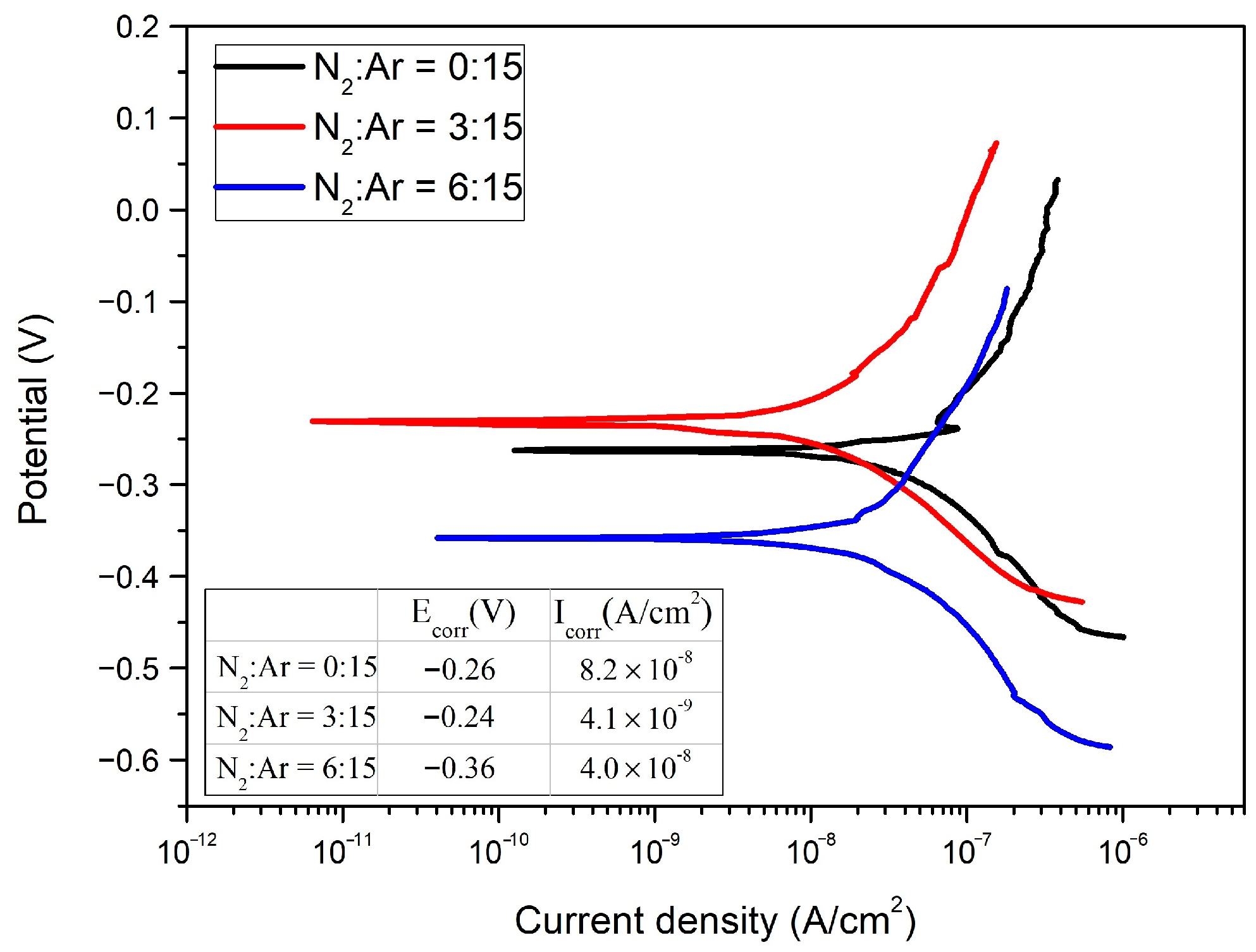
Figure 6 shows the potentiodynamic polarization curves of the CrNx coatings deposited at N2:Ar flow ratios of 0:15, 3:15 and 6:15 in a 3.5 wt.% NaCl aqueous solution. The anodic curves of the Cr coating show a passive region, which can be attributed to the non-conductive oxide thin film formed on the coating surface [31]. In contrast, no clearly passive region was observed in both CN-3 and Cr2N coating, indicating that the 304 stainless steel substrate was actively dissolving. The cathodic curves of these three coatings can presumably be associated with the oxygen reduction reaction. In magnetron sputtering deposited coatings, the voids or continuous columnar grain boundaries growing through the coatings are the solution path to the substrate. Since there were fewer voids or continuous columnar grain boundaries in the column-free CN-3 coating, less oxygen could be diffused to the substrate, resulting in an acceleration of cathodic polarization and, thereby, a lower corrosion current density. The corrosion potentials (Ecorr) and corrosion current densities (Icorr) of these coated samples were calculated and are listed in the table presented in Figure 6. The Icorr value of the column-free CN-3 coating was 4.1 × 10⁻⁹ A/cm2, which was just 1/20 and 1/10 that of Cr and Cr2N coating, respectively. The column-free CN-3 coating also exhibited a less negative corrosion potential than both the Cr and Cr2N coatings. In addition, the Icorr values of column-free CN-3 coating were also significantly lower than those of CrN coating deposited by arc ion plating (2.9 × 10⁻⁷ A/cm2) [32] and Cr coating fabricated by electrodeposition (0.4~3.6 × 10⁻⁶ A/cm2) [33], indicating that CN-3 coating has better anti-corrosion capabilities.

4. Conclusions

CrNx coatings with nitrogen content less than 31.7 at.% were deposited using a CFUBMS by varying N2:Ar flow ratio. The phase structure of the CrNx coating evolved from the bcc Cr phase to the N interstited bcc Cr(N) phase as N2:Ar flow ratio increased from 0:15 to 2:15, and then to a mixture of bcc Cr(N) and hcp Cr2N phase at N2:Ar flow ratio of 3:15. A single Cr2N phase was formed as the N2:Ar flow ratio increased to 6:15. The CrNx coating deposited at N2:Ar flow ratio of 3:15 exhibited a dense column-free structure, while the other CrNx coatings were all columnar structured. This demonstrates that the column-free CrNx coating was composed of an N-incorporated Cr(N) solid solution matrix with a high number of point defects and a Cr(N) matrix with dispersed Cr2N nanocrystallines. The formation of a dense column-free structure can be attributed to the formation of a high number of point defects in the Cr(N) grains, as well as the pinning effect of the Cr2N nanocrystallines dispersed in the Cr(N) matrix, which is achieved by adequate ion bombardment on the substrate during coating growth. The column-free CrNx coating exhibits a hardness of 33.7 GPa, which is 2.6 times that of the Cr coating. The hardness enhancement was related to the solid solution hardening of N incorporating into the Cr grains and the precipitation strengthening effect of the Cr2N nanocrystllines dispersed in the Cr(N) matrix. The column-free CrNx coating also exhibited a lower negative corrosion potential and corrosion current density than the other CrNx coating. Its corrosion current density value was just 1/20 of that of Cr coating.

Author Contributions

Conceptualization, T.W.; Investigation, T.W., Y.W. and Q.C.; Resources, Y.W. and S.Y.; Supervision, G.Z.; Writing – original draft, T.W.; Writing – review & editing, S.Y and G.Z. All authors have read and agreed to the published version of the manuscript.

Funding

This research was funded by the National Natural Science Foundation of China (Grant Nos. 51601144, 52074219 and 52005403).

Institutional Review Board Statement

Not applicable.

Informed Consent Statement

Not applicable.

Data Availability Statement

Not applicable.

Conflicts of Interest

The authors declare no conflict of interest.

References

  1. Tabrizi, A.T.; Aghajani, H. Study through Diverse Synthesis Methods of Chromium Nitride Thin Layers: A Review. J. Surf. Investig. X-ray 2021, 15, 1217–1224. [Google Scholar] [CrossRef]
  2. Fenker, M.; Balzer, M.; Kappl, H. Corrosion protection with hard coatings on steel: Past approaches and current research efforts. Surf. Coat. Technol. 2014, 257, 182–205. [Google Scholar] [CrossRef]
  3. Kashkarov, E.B.; Obrosov, A.; Sutygina, A.N.; Uludintceva, E.; Mitrofanov, A.; Weiß, S. Hydrogen Permeation, and Mechanical and Tribological Behavior, of CrNx Coatings Deposited at Various Bias Voltages on IN718 by Direct Current Reactive Sputtering. Coatings 2018, 8, 66. [Google Scholar] [CrossRef]
  4. Shan, L.; Wang, Y.; Li, J.; Chen, J. Effect of N2 flow rate on microstructure and mechanical properties of PVD CrNx coatings for tribological application in seawater. Surf. Coat. Technol. 2014, 242, 74–82. [Google Scholar] [CrossRef]
  5. Tabrizi, A.T.; Aghajan, H.; Laleh, F.F. Tribological characterization of hybrid chromium nitride thin layer synthesized on titanium. Surf. Coat. Technol. 2021, 419, 127317. [Google Scholar] [CrossRef]
  6. Forniés, E.; Galindo, R.E.; Sánchez, O.; Albella, J.M. Growth of CrNx films by DC reactive magnetron sputtering at constant N2/Ar gas flow. Surf. Coat. Technol. 2006, 200, 6047–6053. [Google Scholar] [CrossRef]
  7. Zhang, G.A.; Yan, P.X.; Wang, P.; Chen, Y.M.; Zhang, J.Y. Influence of nitrogen content on the structural, electrical and mechanical properties of CrNx thin films. Mat. Sci. Eng. A 2007, 460, 301–305. [Google Scholar] [CrossRef]
  8. Qi, A.; Wu, Z.; Zhang, D.; Wang, J.; Wang, Z. Effect of sputtering power on the chemical composition, microstructure and mechanical properties of CrNx hard coatings deposited by reactive magnetron sputtering. Vacuum 2017, 145, 136–143. [Google Scholar] [CrossRef]
  9. Lin, J.; Wu, Z.L.; Zhang, X.H.; Mishra, B.; Moore, J.J.; Sproul, W.D. A comparative study of CrNx coatings synthesized by dc and pulsed dc magnetron sputtering. Thin Solid Film. 2009, 517, 1887–1894. [Google Scholar] [CrossRef]
  10. Zhang, D.; Zuo, X.; Wang, Z.; Li, H.; Chen, R.; Wang, A.; Ke, P. Comparative study on protective properties of CrN coatings on the ABS substrate by DCMS and HiPIMS techniques. Surf. Coat. Technol. 2020, 394, 125890. [Google Scholar] [CrossRef]
  11. Ruden, A.; Restrepo-Parra, E.; Paladines, A.U.; Sequeda, F. Corrosion resistance of CrN thin films produced by dc magnetron sputtering. Appl. Surf. Sci. 2013, 270, 150–156. [Google Scholar] [CrossRef]
  12. Petrov, I.; Barna, P.B.; Hultman, L.; Greene, J.E. Microstructural evolution during film growth. J. Vac. Sci. Technol. A 2003, 21, S117–S128. [Google Scholar] [CrossRef]
  13. Hurkmans, T.; Lewis, D.B.; Paritong, H.; Brooks, J.S.; Münz, W.D. Influence of ion bombardment on structure and properties of unbalanced magnetron grown CrNx coatings. Surf. Coat. Technol. 1999, 114, 52–59. [Google Scholar] [CrossRef]
  14. Olay, J.J.; Rodil, S.E.; Muhl, S.; Sánchez, E. Comparative study of chromium nitride coatings deposited by unbalanced and balanced magnetron sputtering. Thin Solid Film. 2005, 474, 119–126. [Google Scholar] [CrossRef]
  15. Lin, J.; Sproul, W.D.; Moore, J.J.; Wu, Z.L.; Lee, S.L. Effect of negative substrate bias voltage on the structure and properties of CrN films deposited by modulated pulsed power (MPP) magnetron sputtering. J. Phys. D Appl. Phys. 2011, 44, 425305. [Google Scholar] [CrossRef]
  16. Lin, J.; Moore, J.J.; Sproul, W.D.; Mishra, B.; Wu, Z.L.; Wang, J. The structure and properties of chromium nitride coatings deposited using dc, pulsed dc and modulated pulse power magnetron sputtering. Surf. Coat. Technol. 2010, 204, 2230–2239. [Google Scholar] [CrossRef]
  17. Gui, B.; Zhou, H.; Liu, X.; Zhang, K.; Hu, H.; Yang, L.; Zhang, Y. Influence of N2 flow rate on microstructure and properties of CrNx ceramic films prepared by MPP technique at low temperature. Ceram. Int. 2021, 47, 20875–20884. [Google Scholar] [CrossRef]
  18. Greczynski, G.; Jensen, J.; Böhlmark, J.; Hultman, L. Microstructure control of CrNx films during high power impulse magnetron sputtering. Surf. Coat. Technol. 2010, 205, 118–130. [Google Scholar] [CrossRef]
  19. Greczynski, G.; Jensen, J.; Hultman, L. CrNx Films Prepared by DC Magnetron Sputtering and High-Power Pulsed Magnetron Sputtering: A Comparative Study. IEEE Trans. Plasma Sci. 2010, 38, 3046–3056. [Google Scholar] [CrossRef]
  20. Fu, L.S.; Dai, W.; Wang, Q.M.; Zeng, K. Microstructures and mechanical properties of CrN coatings deposited by HIPIMS. Mater. Sci. Forum 2016, 836, 234–241. [Google Scholar] [CrossRef]
  21. Greczynski, G.; Lu, J.; Tengstrand, O.; Petrov, I.; Greene, J.E.; Hultman, L. Nitrogen-doped bcc-Cr films: Combining ceramic hardness with metallic toughness and conductivity. Scripta Mater. 2016, 122, 40–44. [Google Scholar] [CrossRef]
  22. Ferreira, F.; Oliveira, J.C.; Cavaleiro, A. CrN thin films deposited by HiPIMS in DOMS mode. Surf. Coat. Technol. 2016, 291, 365–375. [Google Scholar] [CrossRef]
  23. Arnell, R.D.; Kelly, P.J. Recent advances in magnetron sputtering. Surf. Coat. Technol. 1999, 112, 170–176. [Google Scholar] [CrossRef]
  24. NIST Data Base. Available online: https://srdata.nist.gov/xps/ (accessed on 26 August 2022).
  25. Eriksson, M.; Sainio, J.; Lahtinen, J. Chromium deposition on ordered alumina films: An x-ray photoelectron spectroscopy study of the interaction with oxygen. J. Chem. Phys. 2002, 116, 3870–3874. [Google Scholar] [CrossRef]
  26. Kajikawa, Y.; Noda, S.; Komiyama, H. Comprehensive perspective on the mechanism of preferred orientation in reactive-sputter-deposited nitrides. J. Vac. Sci. Technol. A 2003, 21, 1943–1954. [Google Scholar] [CrossRef]
  27. Moelans, N.; Blanpain, B.; Wollants, P. Pinning effect of second-phase particles on grain growth in polycrystalline films studied by 3-D phase field simulations. Acta Mater. 2007, 55, 2173–2182. [Google Scholar] [CrossRef]
  28. McHale, A.E. Phase Equilibrium Diagrams-Borides, Carbides and Nitrides; The American Ceramic Society: Westerville, OH, USA, 1994; Volume X, p. 451. [Google Scholar]
  29. Matthews, A.; Franklin, S.; Holmberg, K. Tribological coatings: Contact mechanisms and selection. J. Phy. D Appl. Phy. 2007, 40, 5463. [Google Scholar] [CrossRef]
  30. Chen, X.; Du, Y.; Chung, Y.W. Commentary on using H/E and H3/E2 as proxies for fracture toughness of hard coatings. Thin Solid Film. 2019, 688, 137265. [Google Scholar] [CrossRef]
  31. Lansdell, P.A.W.; Farr, J.P.G. A comparison of the surface chemistries of chromium electroplated finishes. Trans. IMF 2004, 82, 105–113. [Google Scholar] [CrossRef]
  32. Wang, L.; Wang, M.; Chen, H. Corrosion mechanism investigation of TiAlN/CrN superlattice coating by multi-arc ion plating in 3.5 wt% NaCl solution. Surf. Coat. Technol. 2020, 391, 125660. [Google Scholar] [CrossRef]
  33. Imaz, N.; Ostra, M.; Vidal, M.; Díez, J.A.; Sarret, M.; García-Lecina, E. Corrosion behaviour of chromium coatings obtained by direct and reverse pulse plating electrodeposition in NaCl aqueous solution. Corros. Sci. 2014, 78, 251–259. [Google Scholar] [CrossRef]
Figure 1. XRD patterns (a) and average grain sizes (b) of the CrNx coating deposited at various N2:Ar flow ratios (▪).
Coatings 12 01327 g001
Figure 2. Cr 2p XPS spectra of CrNx coating deposited at N2:Ar flow ratios of 0:15, 3:15 and 6:15.
Coatings 12 01327 g002
Figure 3. Cross-sectional and surface SEM micrographs of the CrNx coating deposited at various N2:Ar flow ratios: (a) N2:Ar = 0:15, (b) N2:Ar = 1:15, (c) N2:Ar = 2:15, (d) N2:Ar = 3:15, (e) N2:Ar = 4:15 and (f) N2:Ar = 6:15.
Coatings 12 01327 g003
Figure 4. Cross-sectional TEM and HRTEM micrographs of Cr and column-free CN-3 coating, (a,b) Cr coating, (ce) CN-3 coating, (d,e) corresponding to zone I and zone II in (c), respectively.
Coatings 12 01327 g004
Figure 5. Hardness and elastic modulus of the CrNx coatings deposited at various N2:Ar flow ratios.
Coatings 12 01327 g005
Figure 6. Potentiodynamic polarization curves of CrNx coatings deposited at N2:Ar flow ratios of 0:15, 3:15 and 6:15.
Coatings 12 01327 g006
Table 1. Summary of deposition parameters, coating structure and mechanical properties of the CrNx coating deposited at various N2:Ar flow ratios.
Sample
ID
N2:Ar
Flow Ratio
Chemical Composition (at.%)Coating
Thickness
(μm)
H/EH3/E*2
CrN
Cr0:15100-1.320.0420.019
CN-11:1595.94.11.220.0530.039
CN-22:1591.48.61.250.0760.122
CN-33:1585.214.81.130.0950.254
CN-44:1578.821.21.260.0810.141
CN-66:1562.331.71.240.0880.197
Publisher’s Note: MDPI stays neutral with regard to jurisdictional claims in published maps and institutional affiliations.