Abstract
The paper presents the results of theoretical and experimental research on tribotechnical characteristics: tool wear on the back surface, tool durability period, critical length of the cutting path before blunting, adhesion component of the friction coefficient, contact processes, temperature, and force dependences for the application of innovative nanostructured multilayer composite coatings on a tool for milling of titanium alloys. The proposed thermodynamic model of cutting tool wear allows us to determine the ways by which cutting tool wear intensity decreases and the conditions of increase in cutting tool wear resistance with wear-resistant coatings. A substantial increase in wear resistance of end mills when processing titanium alloys with the use of innovative multilayer nanostructured coatings is established, in particular an improvement of an average of 1.5–2 times. These positive results are related to a significant decrease in temperature–force loading in the cutting zone, a decrease in the friction coefficient (adhesion component), and the phenomenon of adaptation (self-organization) of friction surfaces during cutting by tools with wear-resistant coatings, contributing to the formation of films of various compounds with shielding, protective, and lubricating properties.
1. Introduction
The rapid growth of modern machine-building production places increased demands on machining. High-productivity mechatronic systems require increasing the reliability and serviceability of cutting tools by, first, using various methods to improve the cutting properties of tools (hardening technologies and the use of coolant and wear-resistant coatings and their combinations); second, developing modern methods to evaluate the tribotechnical properties of cutting tools; and, third, making scientifically justified choices of cutting modes, taking into account the characteristics of contact processes (temperature and force of cutting).
Regarding the problem of improving the serviceability of cutting tools and technological reliability of multitool and multitransition machining on machine tools with control systems, the issues of wear, fracture, strength, and stress–strain state of cutting tools and the study of thermal and contact phenomena are topics of the fundamental research of many scientists [1,2,3,4,5]. The results of these works allowed the study of the physical mechanisms of cutting tool wear in a wide range of changing elements of the cutting regime and solutions for optimization and control problems of the cutting process and played a major role in the formation of modern concepts in the theory of material cutting.
At the same time, the use of mechatronic systems equipped with high-speed numerical control (NC) and adaptive control (AdC) [6,7,8] machines solves extremely important problems of increasing machining productivity and automation of individual and small-scale production widespread in modern mechanical engineering, but metal-cutting equipment of turning and milling groups has a considerable cost, which has led to high requirements for the scientific validity of cutting modes.
In the manufacture of parts of heavily loaded high-temperature tribocouplings, more and more are made of innovative materials: with unique physical and mechanical properties and, therefore, with low machinability by cutting; in terms of their geometric shape, they mainly represent large-sized complex shaped bodies: bodies, disks, shafts, rotors, flanges, etc. Their work takes place in harsh conditions of simultaneous and long exposure to high temperatures and specific force loads, with high requirements in terms of both accuracy and quality of surface processing. The small dimensional tolerances are due not only to the requirements of interchangeability of the mating surfaces but also to the specific conditions of “high accuracy”, due to which even free dimensions must have small tolerances. The machining of the parts listed above constitutes a significant share of milling operations. The technological problems encountered in the production of each of the above varieties of parts are somewhat different. For example, end milling of a long-sized workpiece with a relatively small thickness is characterized by the large suppleness of the part, so special devices must be developed to create constant stiffness across the entire blade. When machining hollow shafts and rotors made of titanium alloys, it can be difficult to mill slotted and toothed parts due to their long length. However, there is also a general problem of machining such parts associated with the low wear resistance of metal-cutting tools [7,8,9,10,11,12,13].
Nanostructured coatings are one of the typical small-sized objects, which are intensively studied due to the interest in identifying the features of the nanocrystalline state, characterized usually by sizes less than 100 nm [14,15,16]. As was already noted, metal-cutting tools, in most cases and for a few reasons, work in conditions of intermittent cutting and are exposed to alternating thermomechanical influence, leading to their rather intensive destruction in the form of chipping and active cracking. Changes in thermal–physical, physical–mechanical, and crystallochemical characteristics influence tool serviceability. It is known [17,18] that the modification of cutting tool properties by applying multifunctional nanostructured coatings on its working surfaces is one of the most effective ways to improve its reliability. The currently available equipment and technological processes allow the synthesis of multilayer coatings with multicomponent composite architecture, with a nanoscale thickness of nanolayers on modern and highly efficient facilities by various methods, including PVD with magnetic arc filtration, magnetron, and multifunctional high-energy, to modify the surfaces of metal-cutting tools. At the same time, many studies [18,19,20] have established unique properties that are unique only to modern multifunctional nanostructured coatings. Nano-objects are interesting, on the one hand, as metal-like compounds and, on the other hand, as typical brittle phases, not to mention the numerous applications of materials based on embedding phases. In this regard, data on the structure and properties of these compounds in the nanocrystalline state appear to be important for both theoretical materials science and applications. The specific properties of nanostructured coatings are largely due to the peculiarities of their structure: the high-volume fraction of interfaces, the strong binding energy of adjacent phases, the absence of dislocations within nanocrystallites, the implementation of deformation by grain boundary slip, the presence of intergranular amorphous interlayers, and the change in the mutual solubility of components in the embedding phases. All these features allow the achievement of record values of physical, chemical, mechanical, and tribological properties of the material during the transition to the nanostructured state [17,18].
According to research [21,22], control of the technological process of the formation of nanostructured coatings allows the reception of compositions with variable properties depending on the percentage ratio of components. The hardness, friction coefficient, surface roughness, and coating color change. All this makes it possible to optimize the coating properties for a specific task. Applications include cutting, shaping, stamping, and other tools. For example, for TiZrN, high hardness, thermodynamic stability, and the strength of connection are caused by the high similarity of structures and the close sizes of atoms providing the presence of significant areas of mutual solubility of atoms Ti and alloying component Zr in corresponding nitrides. The maximum microhardness of coating TiZrN of 32.2 GPa is observed at the content of 6%–10% Zr, which exceeds the value of Hµ for coating TiN of 22%. The covering (Ti-Zr)CN on the basis of carbonitrides Ti and Zr, the microhardness of which corresponds to 64 GPa, is relative. In research [13,14,15], the extreme character of change in the intensity of wear of the cutting tool depending on the structure of the nanostructured coating is established. During the processing of workpieces from steels 12 × 18H10T, the minimum intensity of wear was observed at plates from alloy BK6 with TiZrN coating at a content of 8%–16% Zr. It is established that the minimum wear rate of the plates with carbonitride coating (Ti-Zr)CN corresponds to the same content of the alloying component as that of the plates with nitride-based coating. The minimum wear is observed at the content of acetylene of 25%–35% and 20%–25% when processing workpieces made of 12X18H10T steel. Studies of the machining process and the thermal and stress state of the cutting tool wedge have established that the coatings TiZrN and (Ti-Zr)CN increase the number of cycles before all longitudinal cracks escape to the back surface compared to the cutting tool with conventional coating by five times, and for nanostructured coatings TiZrN and (Ti-Zr)CN, by 8 and 6.25 times, respectively [13]. Thus, it can be concluded that nanostructured coatings allow an increase in the serviceability of cutting tools due to management of the parameters of coating structure, directionally controlled, which can significantly change coating properties; provide high crack resistance, strength properties, and a high level of compressive residual stresses restraining processes of the formation and development of cracks; and provide a low level of contact and thermal loads, minimizing processes of coating destruction.
Proceeding from the above statements, the purpose of this work is to increase the efficiency of milling of titanium alloys by investigating tribotechnical properties and developing modern innovative wear-resistant coatings based on thermodynamic analysis of contact processes.
The set goal of the work is achieved by describing the thermodynamic model of cutting tool wear, considering the influence of temperature, force parameters, and contact processes during blade cutting by cutting tools with nanostructured multilayer wear-resistant coatings; developing experimental research methods (wear resistance, temperature and force, adhesion, metal science, and others) and conducting them; and analyzing the obtained results.
2. Theoretical and Experimental Background
Metal cutting, by its physical nature, is a complex process [12,13,14,15]; high pressures (up to 2000 MPa and more), high strain rates (up to 106 s−1), increased temperature (up to 1200–1500 K), etc., occur on the contact surfaces of the cutting tool with the machined material. This creates favorable conditions for the development of adhesion, mutual diffusion, oxidation, and hydrogen saturation of surfaces, changes in their structural and phase composition, and generation of electromotive force (EMF). These phenomena have a significant impact on the state and properties of the contact surfaces of the tool and the machined material.
One of the main sources of heat and factors of the formation of near-surface layers during cutting is friction. Since it occurs at high temperatures under conditions of contact juvenility and with the presence of plastic deformations, the adhesion (molecular) component dominates in the adhesion processes [16,17,18]. The relative sliding of the contact surfaces of the tool and the workpiece is accompanied by a continuous process of adhesion spot formation and shearing. The tool surface is under the action of shear stresses, causing the material particles to shear away from the surface in places. Usually, such shearing is much greater on the softer material’s side, but studies using [19,20,21,22] electron microscopy show that there is always some transfer of particles from the harder material (tooling) to the softer material (machinable) at the same time.
At the present time, when describing contact processes and the wear of a cutting tool, a complex power representation proposed in the works of Professors Y.G. Kabaldin, A.D. Makarov, V.N. Poduraev, S.S. Silin, N.V. Talantov, and other scientists is used [1,2,3,4,5,6,7].
To describe the contact processes, friction, and wear of cutting tools with wear-resistant coatings, a dynamic process such as cutting is considered from the position of nonequilibrium thermodynamics, taking into account and specifying the components of energy balance of the process of interaction of the machining material and surfaces of the cutting tool.
It is known [10,20] that the first law of thermodynamics for friction and wear processes can be written down by the equation:
where Wf is the work of friction forces; Q is the amount of heat released under friction; and ΔU is the change in the internal energy of the friction contact zone.
Wf = Q + ΔU
The change in internal energy can be represented as
where ΔWmν is energy spent on the separation of the wear particle, ΔWph is energy spent on structural phase transformations, ΔWΔd is energy spent on plastic deformation, ΔWΔf is energy spent on the formation of rubbing surfaces, etc.
ΔU = ΔWmν + ΔWph + ΔWΔd + ΔWΔf
Since, at present, there are no analytical dependences by which all components of expression (2) can be estimated, let us assume, at first approximation, that during friction, there will be dissipation of a part of internal energy at the expense of
- -
- Plastic deformation of a single microuneven (microcutting) as a result of shear by the average diameter of the contact spot;
- -
- The form modification of the surface layer of the wear material as a result of the formation of a wear fragment.
Using the principles of nonequilibrium thermodynamics, an irreversible dynamic process such as wear can be most effectively described by means of dissipative functions (DF), which are the rate of change ΔWi/dτ of energy spent on a process (for example, plastic deformation of the machined material), related to a unit of actual contact area Ar.
According to the laws of nonequilibrium thermodynamics, to ensure the irreversibility of a process, it is necessary to have a generalized thermodynamic flux and force, i.e., supported by gradients of the state values of the thermodynamic system, preventing the inverse process and taken with the opposite sign. The DF of such a process is equal to the product of the generalized flux and force
where is generalized flux and is generalized force.
In the first approximation, the change in internal energy of the frictional thermodynamic system ΔU can be represented as the sum of energy spent on dispersion (wear) of the tool and energy of elastoplastic deformation of the processed material. Unfortunately, it is currently impossible to make a more precise quantitative assessment of the energies expended on structural phase transformations, etc., but an analysis of literature data allows us to qualitatively combine these moments and simplify and account for the other components. In this case, the DF balance equation can be represented as
where is the DF of the friction process, ψd is the DF of the shear plastic deformation process of the machined material by the mean diameter of the contact spot, and ψs is the DF of dispersion and shape change of the surface layer of the wearable tool material.
Using the methods of the theory of adaptation (self-organization) of nonequilibrium systems, physical kinetics, and force laws of the theory of strength and plasticity, the mechanochemistry of metals, thermal physics and cutting mechanics, and the components of the balance equation for the working conditions of tools with wear-resistant coatings are considered and specified.
Based on the analysis of contact processes, the friction process DF is presented as a change in the specific work of external forces, referred to as the unit of contact area of the tool with chips and workpieces, considering the influence of the shape and radius of the cutting edge and the current value of cutting force:
where is the current value of cutting force; is the current value of cutting speed; and c are the contact lengths of the cutter with the chip and with the workpiece, respectively, on the front and back surfaces; b is the width of the cut layer; and is the friction factor.
The plastic deformation of the processed material is determined by the current θ(τ) and initial θ0 values of the cutting temperature, the degree of plastic deformation ∆γ, the short-term yield strength and the shear modulus of the processed material, and the resonant frequency of self-oscillations in the contact zone fr:
The DF of the form change of the tool material is determined based on the analysis of the form stability of the cutting edge, the model of damage accumulation in the contact layers of the tool, and the probabilistic nature of the wear particle separation set out in the works of Professor T.N. Loladze, as well as the specification of the wear scheme:
where is wear intensity, V is cutting speed, HVt/HVm is the ratio of microhardness of the tool and machined materials in the conditional plane of shear [4], α is the index, taking into account the influence of cutting temperature on microhardness, erf (P (τ)) is the probability of wear particle separation, is normal specific load in the contact zone, E is the modulus of elasticity of the machined material, σT is the short-term yield strength of the tool material, and is Poisson’s coefficient.
From the solution of the system of Equations (6)–(8) concerning the cutting tool wear rate, the expression is obtained:
where are dimensionless criteria, respectively, considering physical and mechanical properties of the machined material and the character of cutting temperature change.
From Equation (9), it follows that the main ways of reducing the intensity of blade cutting tool wear are
- -
- Reducing the temperature and cutting force.
- -
- Reducing the friction coefficient f (adhesive component) of the frictional contact with the machined material (due to the formation of secondary structures and phases on the working surfaces as products of adaptation (self-organization) of the tribosystem).
- -
- Increasing the hardness ratio of the tool’s contact surfaces and the workpiece (by reducing the dependence of the physical and mechanical properties of the contact surfaces on the temperature in the working zone, considering the phenomena of adaptation (self-organization) during friction) [12,13,23,24,25].
At the present time, the above can be achieved by developing, implementing, and researching innovative multilayer composite coatings on the cutting tool for blade cutting processing, which have not only unique strength properties but also the ability to adapt to external influences with subsequent improvement of operational properties.
It is known that the temperature and cutting forces can have a two-fold influence on the intensity of cutting tool wear: on the one hand, increasing temperature reduces the direct effect of the force factor, and on the other hand, increasing temperature leads to the formation of secondary structures and phases on frictional contact with a corresponding change in physical and mechanical properties. Consequently, when creating tool materials and wear-resistant coatings with a friction adaptation effect, it is necessary to consider the specified region of cutting modes and the cutting temperature interval corresponding to this region [26,27,28,29,30,31].
3. Materials and Methods
Experimental research during milling was carried out on certified equipment to ensure the reliability of the obtained test results, specifically on vertical milling machines of normal accuracy and rigidity “VM 127M” (Votkinskiy Machine Building Plant, Votkinsk, Russia) and “Knuth WF 4.1” (KNUTH, Wasbek, Germany) (Figure 1). Figure 1 of vertical milling machine “VM 127M” shows the complexity of the equipment for measuring and recording the components of forces and cutting temperature, from left to right: dynamometer amplifier; PC with software “KISTLER” (version 2825A-03-2); PC for recording cutting temperature with TEMS converter for the temperature; millivoltmeter on the machine table; and three-component dynamometer “KISTLER” with a workpiece mounted on it.
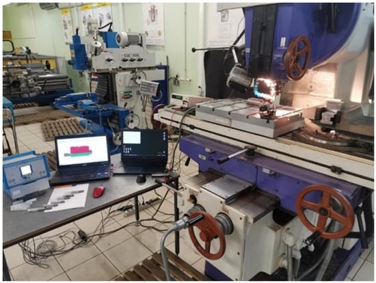
Figure 1.
Vertical milling machine VM 127M.
To investigate wear laws of cutting tools at face milling with carbide end mills (diameter d = 12 mm; number of teeth z = 4; with geometry of cutting part of helix angle ω = 30°; forward angle γ = 10°; and back angle α = 4°) of H10F grade with various coatings, titanium alloys—Ti64 and Ti811—were used as a machined material. Chemical composition, physical and mechanical properties, and heat treatment of the alloys under study are presented in Table 1 and Table 2.

Table 1.
Chemical composition of the materials to be machined.
Table 2.
Physical and mechanical properties of machined materials.
The study of the machinability of titanium alloys in full-scale tests was carried out as applied to the conditions of semifinishing and finishing machining: at n = 2000 rpm; S = 200 mm/min; ae = 5 mm; and ap = 1.5 mm. In this case, as shown by preliminary experiments and analysis of literature data [32,33,34,35,36], in the conditions of finishing and semifinishing cutting, the determining element of tool wear is the wear chamfer on the rear surface of the cutting wedge. Analysis of the rear surface wear profile showed that the average wear of the rear surface along the main cutting edge is characterized by the smallest variability of the wear measurement results. This parameter at constant values of the front and rear angles of the cutting wedge reflects the dimensional wear resistance of the whole tool. Based on the above, the average width of the rear surface wear chamfer (excluding notches) was used as the investigated tool wear parameter. In the process of milling to ensure the identity of the results and to exclude errors of measurement, the width hr of tool wear chamfer on the back surface was measured using the reading microscope MIR-2M with nozzle MOB-I5 accurate to 0.002 mm at the workplace, and when it reached hr = 0.3–0.4 mm, for additional control and photofixation of the wear pattern, a universal motorized stereo microscope with the possibility of telecommunication “Carl Zeiss Stereo Discovery V12” (ZEISS Microscopy, Oberkochen, Germany) with a visualization system based on the video camera “Zeiss Axiocam 503 Color” (ZEISS Microscopy, Oberkochen, Germany) was used (Figure 2). In this case, the wear of the cutter was measured at certain number of passes, and the cutting path length was set to obtain a picture of all stages of the wear curve (section of the running-in, normal, and catastrophic wear).
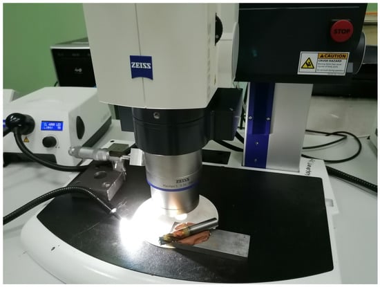
Figure 2.
Working area with motorized stereo microscope “Carl Zeiss Stereo Discovery V12”.
The wear resistance of a cutting tool is characterized by the period of its durability T and is defined as [3,4]:
where T is the durability period (min), l is the cutting path length (m), Sm is the minute feed rate (m/min), hrl is the relative linear, and hsw is the surface wear:
The criterion for the blunting of cutting tools was taken to be = 0.3 mm.
The schematic diagram of temperature and force studies during milling is shown in Figure 3.
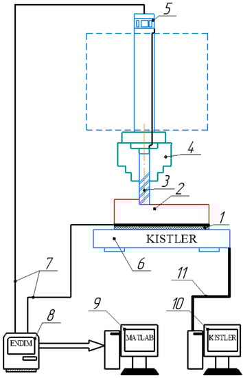
Figure 3.
Schematic diagram of measuring temperature and cutting force components by natural thermocouple method. 1—insulation; 2—workpiece; 3—insulated cutter; 4—chuck; 5—mercury current collector; 6—dynamometer “Kistler”; 7—connecting wire; 8—amplifier–converter; 9—computer for registration of thermal emfs; 10—computer for registration of cutting force components; and 11—connecting bus.
To obtain information about the average contact temperature during cutting with sufficiently high accuracy, we used the simple and reliable natural thermocouple method. The part (2) and cutter (3) were isolated from each other by an insulator (1) to exclude errors from the so-called “parasitic” thermo-EMF. Measurement of thermo-EMF was carried out in intervals of 10–15 s after the beginning of cutting. The mercury current collector (5), digital voltmeter “Endim” (8), and PC (9) were used for registration and recording of the thermo-EMF value [10].
Currently, for research purposes, a set of equipment “Kistler” (Figure 3) is used to measure the components of the cutting force, which provides a high degree of accuracy. The main element of the measuring system is a three-component dynamometer by “Kistler” in the form of a bed for fixing the workpiece from the machined material, model 9253B23 (Kistler Group, Winterthur, Switzerland), the appearance of which is shown in Figure 4.
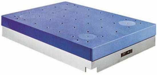
Figure 4.
External view of the 9253B23 dynamometer.
The connection diagram of the main elements of the dynamometer is shown in Figure 5.
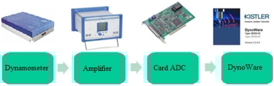
Figure 5.
Wiring diagram.
The resulting force acting on the dynamometer is proportional to the algebraic sum of the corresponding components of the individual forces, which are formed because of the parallel arrangement, as shown in Figure 6. Thus, the dynamometer is a multicomponent force sensor, independent of the point of its application.
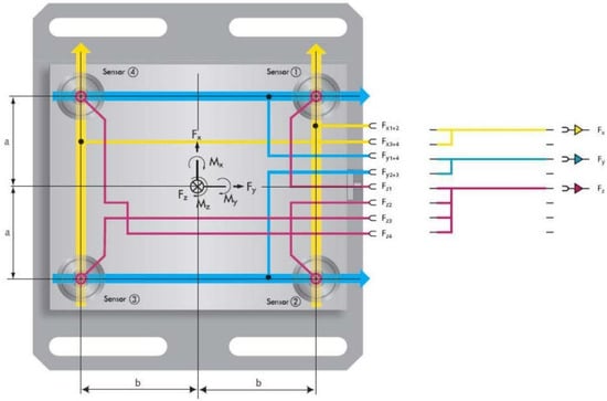
Figure 6.
Structure of a three-component dynamometer. (a, b is the distance from the machining point to the center of the sensor; 1–4 is force sensors; M is moment of force).
To amplify and convert the signal, we used an 8-channel amplifier and converter type 5070A01110 from “Kistler” (Kistler group, Schweiz), the appearance of which is shown in Figure 7.
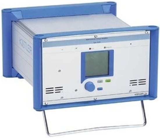
Figure 7.
Exterior view of the amplifier and converter type 5070A01110.
Kistler “DynoWare” software (version 2825A-03-2) is used for data collection and analysis. The “DynoWare” software is versatile, easy to use, and compatible with dynamometers or single- and multicomponent force transducers. “DynoWare” provides continuous visualization of the measured curves during signal analysis and has all necessary mathematical and graphical functions. In addition to the simple configuration of the most important measurement tools, “DynoWare” supports the documentation of measurement processes and the storage of configuration and measurement data.
Easy operation, setup, and monitoring of “Kistler” measuring instruments via RS-232C or IEEE 488 interfaces; powerful graphic capabilities; useful functions for evaluation and calculations; simultaneous data logging from up to eight measuring channels; and recording and evaluation of any physical quantities are possible.
It is known that adhesion wear is most prevalent in machining, and at the same time, to reduce the time to determine the effective coating composition and application modes, as well as reduce the cost of both the tool and cathode material, several adhesion tests were carried out. To estimate the tribotechnical parameters (τnn, prn, and τnn/prn), an experimental method [25] was used. This method is based on the physical model (Figure 8) and the developed setup (Figure 9) [12,26], which in the first approximation reflects real friction and wear conditions at local contact. According to this model, a spherical indentor (1) made of tool material H10F with different coatings (simulating a single rough spot of rubbing solids), squeezed by two plane-parallel samples (2) made of titanium alloys Ti64 and Ti811 (with high accuracy and cleanness of contact surfaces), rotates under the load N around its own axis. The force Fex expended on the indentor rotation and applied to the tether (3) placed in the disk slot (4) is mainly related to the shear strength τnn of the adhesion bonds. The other end of the cable is connected to the elastic elements (9, 10) and the recording device by means of the wire (11) on which the drive forces for the rotation of the indentor (1) are recorded. Ensuring the temperature regime in the contact zone of the indentor with the samples of the processed material in a wide range of variation (0–1300 °C) uses the electrical contact method, and a high voltage is supplied from the power-controlled transformer to the terminals (5) isolated from the housing.
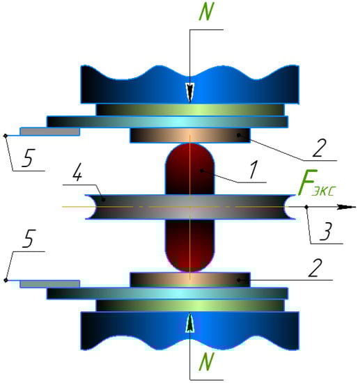
Figure 8.
Model of frictional contact. 1—Spherocylindrical indenters of the tool material, 2—cylindrical samples of the same machined material, 3—traction cable, 4—disk with a slot for cable 3 and for mounting 1, and 5—electrical wiring.
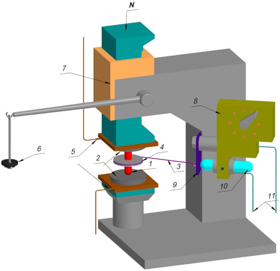
Figure 9.
Installation for adhesion testing. 1—Spherocylindrical indenters of the tool material, 2—cylindrical samples of the same machined material, 3—traction cable, 4—disk with a slot for cable 3 and for mounting 1, 5—electrical wiring, 6—the device for loading, 7—rack-and-gear mechanism, 8—bracket for mounting the elastic element 9 and strain gauge movement 10, and 11—wiring to register movement, N—applied force.
At the same time, tribotechnical characteristics such as adhesive bond shear strength (τnn), normal contact stresses (prn), and adhesion component of the friction coefficient (fa) were determined. Examples of samples for adhesion studies are shown in Figure 10.
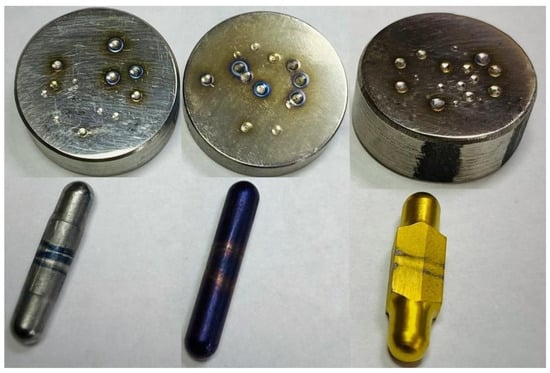
Figure 10.
Samples of machined (flat cylindrical heels) and tool materials (finger cylinders with spherical tips on both sides) with different wear-resistant coatings applied.
The surface morphology and microstructure of the coatings were studied by transmission electron microscopy on JEOL JEM-201 OE (Akishima, Japan) with an accelerating voltage of 200 kV. At the same time, the coatings were deposited on the cemented carbide bottom layer with a thickness of 2.5 to 3 μm for observations. Samples were prepared using the FIB ion beam focusing method on the JEOL-JFIM-2100 system and were thinned to 0.1 μm using Ga ions with an accelerating voltage from a Ga ion source of 30 kV and a current of 2.0 mA. The chemical composition of the secondary structures appearing on the cutter surface during cutting was investigated by the SIMS method. The ion etching rate was on the order of 0.2 monolayers per minute, and the analysis was performed in static mode. The atomic structure of the films formed on the tool surface during cutting was investigated using EELFS and an ESCALAB MK 2 (VG) electron spectrometer. The friction surface was investigated in areas free from adhesion of the workpiece material. A high magnification ratio (2000×) was used. The primary electron energy was Ep = 1000 eV. A fine spectral energy loss pattern was recorded close to the elastically scattering electron line in the 250 eV range. The analysis conditions were chosen to provide the best energy resolution with a good signal intensity ratio [37,38,39,40,41].
Nanostructured composite multilayer coatings for adhesion tests on the tool material indentor and wear-resistant coatings for end mills were applied on three different units: “Platit π311” in the laboratory “Coating Technology and Heat Treatment” with (CrAlSi)N, (CrAlSi)N + DLC (diamond-like carbon), (TiAlSi)N, (CrAlSi)N + epilama, (CrAlSi)N + DLC + epilama, and (TiAlSi)N + epilama; modernized NNV-6 6-I1 at the laboratory “Innovative Materials and Coatings” with IDTI RAS-(TiCrAl)N, (ZrCrAl)N, (ZrMoAl)N, and (ZrMoHfCrAl)N; and “Platit π411” at Technopark “Vityaz” with TiB2, nACo3, nACRo, nACRo+TiB2, nACo3+TiB2, TiB2+epilama, nACo3+epilama, nACRo + epilama, nACo3 + TiB2+epilama, and nACRo+TiB2+epilama, with a coating thickness no more than 10 microns. The grain size of these coatings was in the range of 3 to 5 nanometers. The microhardness for the nACo3 coating was 45 GPa and for the nACRo coating was 42 GPa, with room temperature friction coefficients of 0.35 and 0.45, respectively. At the same time, nACo3–(TiAlSi)N + TiN or AlSiTiN(up) + TiAlSiN + TiN and nACRo–TiAlN or AlCrN is embedded in the amorphous matrix SiN.
4. Experimental Results and Discussion
The analysis of the works of researchers allows us to conclude that the solution to the problem of increasing the wear resistance of cutting tools with different coatings is developing in different directions. At the same time, there is practically no data on the results of experimental research with the indication of cutting modes and specific relationships between “tool-machined material”, application modes, and percentage content of wear-resistant coating elements, as well as their operational characteristics (adhesion coefficient, service life, critical cutting path length, and wear on the rear surface of the cutting tool); this does not allow a comparative analysis of the results obtained in this case. In the works [36,37,38,39,40,41], in search of solutions to the problem, we followed a way of modeling the alloying components (Ti, Cr, Al, and Si) in the composition of nanocomposite coatings (nc-TiAlN/a-SiN, nc-AlCrN/a-SiN, and nc-AlTiCrN/a-SiN), and the increase in the tool service life by 10%–15% on average does not allow substantiation of the improvement of tribotechnical characteristics of wear-resistant coatings, with regard for possible measurement errors.
At the same time, it is known [36,42,43,44,45,46,47,48] that most modern nanostructured multilayer composite coatings used on the cutting tool for blade cutting, under certain contact processes and temperature and force conditions, can improve their tribotechnical characteristics. In particular,
- -
- The nanocomposite coating based on aluminum nitride and titanium nACo3 is a high-tech solid coating applied by physical vacuum deposition and consisting of nanoparticles in a binding amorphous matrix. The uniqueness of the coating lies in the successful combination of physically mutually exclusive parameters: while increasing the hardness, its elasticity increases at the same time;
- -
- The nanocomposite coating based on chrome and aluminum carbonitrides nACRo has very high hardness at elevated cutting temperatures;
- -
- Titanium diboride TiB2 nanocomposite coating is a synthetic, particularly hard, heat-resistant, refractory, and wear-resistant material. These coatings are advantageous due to their high hardness and resilience as well as good abrasion resistance.
- -
- Diamond-like coating (DLC) is a diamond-like carbon material with a tough and friction-reducing coating on top of other conventional wear-resistant coatings in most cases.
The results of experimental studies of the wear resistance of cutting tools with different coatings during milling (Figure 11, Figure 12, Figure 13, Figure 14, Figure 15 and Figure 16) of titanium alloys are presented in the form of graphs of the dependence of tool wear on the rear surface (hr, mm) (Figure 11 and Figure 14) on the critical length of cutting path (l, m) (Figure 13 and Figure 16) and also graphs of the dependence of the durability period on the coating applied to the cutting tool (Figure 12 and Figure 15). The best indices of cutting tool wear resistance (wear on the back surface, critical cutting path length, and tool durability period) were measured as follows:
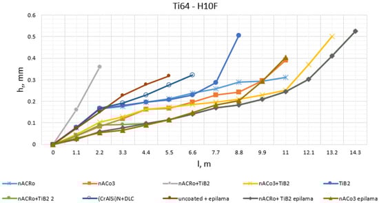
Figure 11.
Effect of the cutting path length (l, m) on the value of wear on the rear surface (hr, mm) during milling of titanium alloy Ti64 by carbide cutters of grade H10F with different coatings (n = 2000 rpm, Smin = 200 mm/min, ae = 5 mm, ap = 1.5 mm).
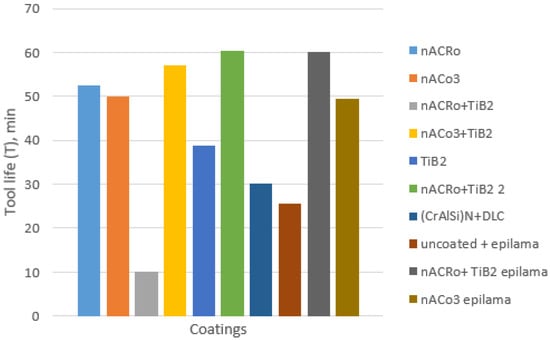
Figure 12.
Durability period when milling titanium alloy Ti64 with tungsten carbide cutters of grade H10F with different coatings.
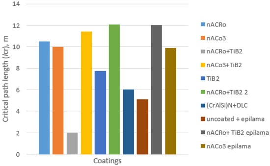
Figure 13.
Critical path length when milling titanium alloy Ti64 with H10F carbide cutters with different coatings.
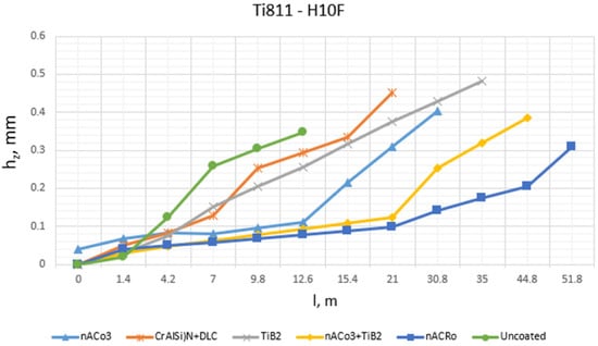
Figure 14.
Effect of the cutting path length (l, m) on the value of wear on the rear surface (hz, mm) during milling of titanium alloy Ti 811 by carbide cutters of grade H10F with different coatings (n = 2000 rpm, Smin = 200 mm/min, ae = 5 mm, ap = 1.5 mm).
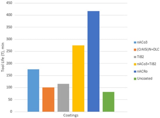
Figure 15.
Durability period when milling titanium alloy Ti811 with tungsten carbide cutters of grade H10F with different coatings.
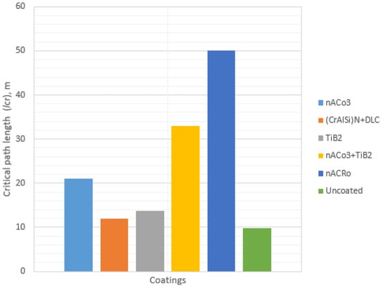
Figure 16.
Critical path length when milling titanium alloy Ti811 with H10F carbide cutters with different coatings.
- -
- Milling of titanium alloy Ti64 was ensured when using wear-resistant coatings: improvement by 2.4 times with “nACRo+TiB2” coating, by 2.2 times with “nACo3+TiB2”, and by 2 times with “nACRo” coating compared to milling without coating;
- -
- Milling of titanium alloy Ti811 was provided with wear-resistant coating: improvement by 4 times with “nACRo” coating and improvement by 2 times with “nACRo+TiB2” coating in comparison with milling without coating.
According to the results of experimental studies, the best indicators of cutting tool wear resistance with different coatings were found as follows:
- -
- Milling of titanium alloy Ti64 was provided when using wear-resistant coatings: improvement by 18% with “nACRo + TiB2” coating and by 17% with “nACRo + TiB2 + epilama” coating in comparison with “nACo3” coating;
- -
- Milling of titanium alloy Ti811 was ensured when using wear-resistant coatings: improvement by 1.8 times with “nACRo” coating and by 1.5 times with “nACo3 + TiB2 + epilama” coating in comparison with “nACo3” coating.
According to the results of field experiments during milling of titanium Ti64 by milling cutters with different durations of titanium diboride application, it was found that
- -
- For milling of Ti64 titanium alloy, an increase in TiB2 coating time of more than 30 min does not contribute to the increase in wear resistance of the milling cutter.
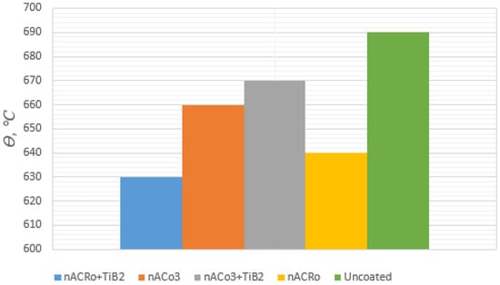
Figure 17.
Cutting temperature (thermal emf) when milling titanium alloy Ti64 at different spindle speeds (n = 2000 rpm; Smin = 200 mm/min, ae = 5 mm, ap = 1.5 mm).
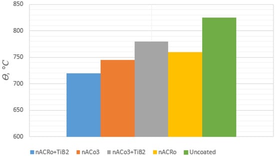
Figure 18.
Cutting temperature when milling titanium alloy Ti811 at different spindle speeds (n = 2000 rpm; Smin = 200 mm/min, ae = 5 mm, ap = 1.5 mm).
According to the results of temperature studies, it was found that
- -
- The lowest cutting temperature value is provided when using “nACRo + TiB2” coating when milling Ti64 and Ti811 titanium alloys, and they are lower by 9% and 12%, respectively, relative to uncoated machining;
- -
- Milling of Ti64 titanium alloy is less heat-intensive compared to Ti811.
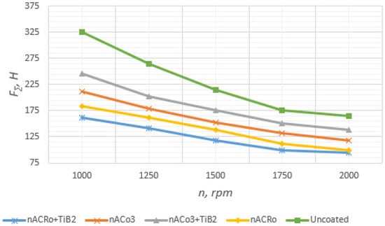
Figure 19.
Total component of cutting force when milling titanium alloy Ti64 at different spindle speeds (Smin = 200 mm/min, ae = 5 mm, ap = 1.5 mm).
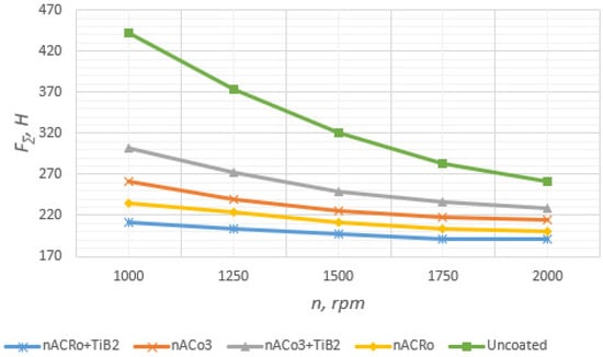
Figure 20.
Total component of cutting force when milling titanium alloy Ti811 at different spindle speeds (Smin = 200 mm/min, ae = 5 mm, ap = 1.5 mm).
According to the results of the conducted force tests, it was found that
- -
- The lowest value of cutting force is provided when using “nACRo3 + TiB2” coating for both titanium alloy Ti64 and alloy Ti811 with 1.5–2 times less force in comparison with milling without coating;
- -
- Milling of titanium alloy Ti64 has less force loading in comparison with Ti811 by 1.5–2 times.
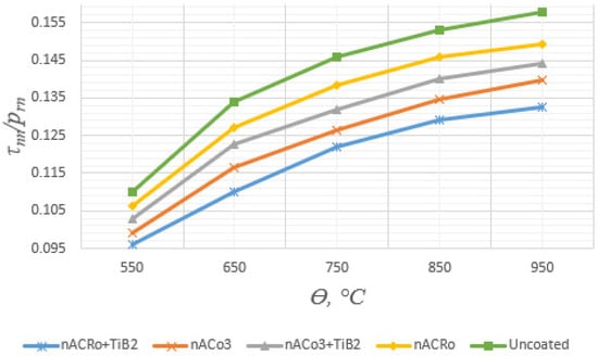
Figure 21.
Temperature dependence of frictional characteristics of plastic contact “Ti64-H10F with coatings”.
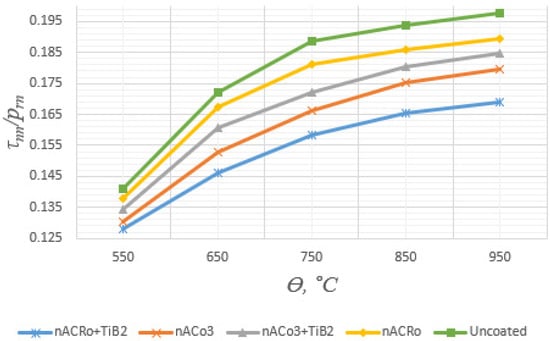
Figure 22.
Temperature dependence of frictional characteristics of plastic contact “Ti811-H10F with coatings”.
Analysis of experimental data has shown that, with increasing contact temperature, the adhesion component of the friction coefficient increases monotonically for all the coatings under study at temperatures corresponding to optimal cutting speeds (according to wear intensity), and the smallest value corresponds to the most favorable composition and technology of their applications. It was found that
- -
- The most effective coatings in terms of contact processes on a single contact spot and adhesion coefficient are the coatings applied on “Platit π411”: nACo3, nACRo, and nACRo + TiB2;
- -
- The lowest coefficient of adhesion interaction between the tool material and the machined material in the whole investigated temperature range is provided by coating nACRo + TiB2 on titanium alloys Ti64 and Ti811, which confirms the best coating adhesion with the substrate and allows using them for high-speed milling.
To explain the mechanism of increasing tribotechnical characteristics of multilayer nanostructured coatings, a series of material science studies of the wells of samples of machined and spherical surfaces of tool materials was carried out (Figure 23, Figure 24 and Figure 25).
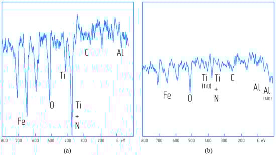
Figure 23.
Auger electron spectra of surfaces of worn nACRo-coated inserts: (a)—at the running-in stage after 3 min from the beginning of cutting; (b)—at the steady-state stage after 20 min from the beginning of cutting.
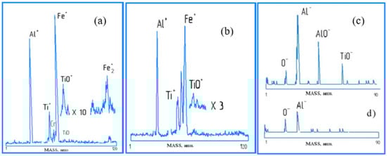
Figure 24.
Spectra of positive (a,b) and negative (c,d) secondary ions of the surface of worn nACRo-coated plates: (a,d)—after 3 min of cutting; (b,c)—after 20 min of cutting.
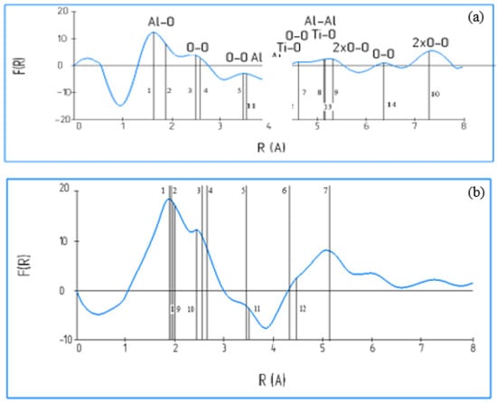
Figure 25.
Fourier transforms on the EELFS close to the elastic scattering electrons for films formed on the surface: (a)—nACRo-coated cutting tool; (b)—binary TiAl alloy after isothermal oxidation in air.
The surface morphology and microstructure of the coatings were investigated by transmission electron microscopy on a JEOL JEM-201 OE unit with an accelerating voltage of 200 kV. At the same time, the coatings were deposited on the cemented carbide bottom layer with a thickness of 2.5 to 3 μm for observations. Samples were prepared using the FIB ion beam focusing method on the JEOL-JFIM-2100 system and were thinned to 0.1 μm using Ga ions with an accelerating voltage of 30 kV and a current of 2.0 mA from a Ga ion source. The chemical composition of the secondary structures appearing on the cutter surface during cutting was investigated by the SIMS method. The ion etching rate was on the order of 0.2 monolayers per minute, and the analysis was performed in static mode. The atomic structure of the films formed on the tool surface during cutting was investigated using EELFS and an ESCALAB MK 2 (VG) electron spectrometer. The friction surface was investigated in areas free from adhesion of the workpiece material. A high magnification ratio (2000×) was used. The primary electron energy was Ep = 1000 eV. A fine spectral energy loss pattern was recorded close to the elastically scattering electron line in the 250 eV range. The conditions for the analysis were chosen to provide the best energy resolution with a good signal intensity ratio [18,48,49,50,51].
Intensive tribo-oxidation of the cutting tool surface occurs during high-speed machining. Figure 24 shows Auger electron spectra for tools with nACRo wear-resistant coating. The oxidation of the contact surfaces is obvious, as evidenced by the presence of large amounts of oxygen in both spectra. The intense ionic peaks correspond to the adhesion zones of the part material. The Ti line is significantly stretched (Figure 24b) in this zone; this is the result of the oxidation process. An increased amount of aluminum oxide is observed in the spectrum of the filtered coatings, which is shown as a shift in the aluminum line to a lower energy zone (60 eV). At the same time, the intensity of the metallic Al LMM line level around 68 eV decreases.
Figure 24a,b show a series of spectra of positive secondary ions for both 3 min of cutting and after 20 min of coating cutting, and Figure 24c,d show spectra of negative secondary ions for both coatings. In both positive secondary spectra, the TiO line intensity is high, and this is due to intense tribo-oxidation, which forms rutile-like films. However, some aluminum oxide is formed only on the surface of the coatings after 20 min, and this effect can be observed on the spectrum of negative secondary ions (Figure 24c). The formation of aluminum oxide films on the cutter surface significantly changes the heat fluxes and heat dissipation into the chip. This is confirmed by images of chip cross-sections after scanning on an electron microscope, and three different zones can be seen in the chip cross-sections.
The atomic structure of the films appearing on the wear zone surface during tribo-oxidation of the nACRo coating was compared with the oxide layer obtained during oxidation of the binary TiAl alloy under equilibrium conditions. Figure 26 shows the Fourier transforms because of mathematical consideration of the fine structure of electron spectra close to the line of elastically scattering electrons. The positions of the peaks on the Fourier transforms correspond to the interatomic distances for the closest coordination spheres. The decoding of the data was based on the analysis of known crystal characteristics of oxides formed on the surface. The positions of the main peaks of the Fourier transforms correspond to the interatomic distances associated with the Al2O3 and TiO2 lattices (Figure 25) [51,52,53,54].
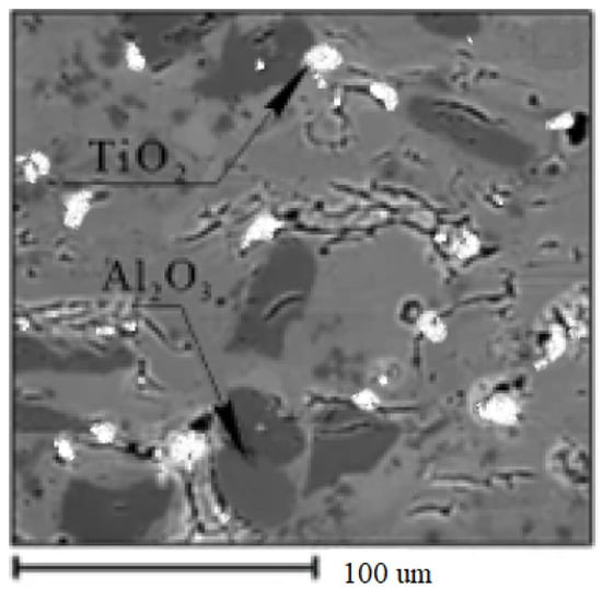
Figure 26.
Results of the micro-X-ray spectral analysis.
In general, the results of metallurgical studies state that the use of such coatings contributes to the reduction in friction forces and cutting tool wear due to the formation of titanium and aluminum oxides. Studies of protective film formation at low and moderate cutting speeds show that there is only one type of protective film formed on the surface because of self-organization phenomena [17,28,29,30]. These films have an amorphous-like structure with high ductility and improved lubricity. More complex phenomena occur during high-speed processing. These are, first, the low-intensity peaks that are found at far atomic distances in the Fourier transforms shown in Figure 25. From this figure, it can be assumed that the films that form during tribo-oxidation under high-speed processing conditions are amorphous-like. These films of aluminum oxide contribute to the reduction in wear because, due to the low thermal conductivity, they prevent the intensive removal of heat generated during cutting into the body of the cutting tool [55,56,57,58,59].
Figure 26 shows the results of the micro-X-ray spectral analysis of the worn surfaces of the cutting tools with nanostructured coatings. Worn and oxidized areas of the cutter surface revealed aluminum and titanium oxides formed during milling with nACRo nanostructured coatings.
5. Conclusions
- The thermodynamic model of cutting tool wear is proposed, allowing us to determine ways to reduce the intensity of cutting tool wear and the dissipative function of the tool material shape change during tool wear, and the conditions for improving the wear resistance of the cutting tool using the phenomenon of adaptation (self-organization) under friction are formulated.
- Experimental studies on the wear resistance of cutting tools with different coatings have shown that, during milling of titanium alloys, a significant increase in wear resistance is provided when using innovative multilayer nanostructured coatings, with an improvement on average of 1.5–2 times.
These positive results are associated with a complex set of phenomena occurring in the contact processes:
Firstly, there is a significant decrease in temperature–force loading in the cutting zone by an average of 15%–25% both in terms of cutting temperature and cutting force components, and this phenomenon, according to numerous studies, can be explained by the formation of secondary structures on the friction surfaces in the form of aluminum and titanium oxides, which have heat-reflecting (shielding) and lubricating properties;
Secondly, it is because of the above reduction in the friction coefficient (adhesive component) in a wide range of temperature changes from 5500 C to 9500 C by 13%–17%.
- 3.
- Important in the analysis are the results of metallurgical research, as the obtained data allow one to assert that, in contact processes, there is a phenomenon of adaptation (self-organization) of friction surfaces at cutting by a tool with wear-resistant coatings, promoting the formation of films of various compounds with shielding, protective, and lubricating properties, in particular Al2O3, TiO2, etc. These films have an amorphous-like structure with high plasticity and improved lubricity. This is confirmed by spectroscopic studies and above all by the low-intensity peaks found at long atomic distances on Fourier transforms.
Author Contributions
Conceptualization, M.S.M.; Methodology, S.R.S. and A.M.M.; Software, A.S.G.; Formal analysis, N.A.S.; Writing—review & editing, A.P.M.; Visualization, D.S.R. All authors have read and agreed to the published version of the manuscript.
Funding
The research was funded by Grant No. 22-19-00670 of the Russian Science Foundation, https://rscf.ru/project/22-19-00670/ (accessed on 27 December 2022).
Institutional Review Board Statement
Not applicable.
Informed Consent Statement
Not applicable.
Data Availability Statement
Not applicable.
Conflicts of Interest
The authors declare no conflict of interest.
References
- Vereshchaka, A.S.; Kushner, V.S. Cutting Materials; Higher School: Moscow, Russia, 2009; 336p. [Google Scholar]
- Kabaldin, Y.G.; Semibratova, M.V.; Kirichenko, V.V. Self-organization in friction processes during cutting. In Proceedings of the Tomsk Polytechnic University Proceedings of TPU, Tomsk, Russia, 25–26 April 2002; Volume 305, pp. 95–100. [Google Scholar]
- Makarov, A.D. Optimization of Cutting Processes; Mechanical Engineering: Moscow, Russia, 1976; 150p. [Google Scholar]
- Loladze, T.N. Durability and Wear Resistance of Cutting Tools; Mechanical Engineering: Moscow, Russia, 1982; 320p. [Google Scholar]
- Matalin, A.A. Engineering Technology: University Textbook; Mechanical Engineering: Moscow, Russia, 1985; 512p. [Google Scholar]
- Zoritkuev, V.C. Identification and Automatic Control of Technological Processes in Machine-Tool Systems: A Training Manual; USATU: Ufa, Russia, 1993; 118p. [Google Scholar]
- Andrievsky, R.A.; Ragulia, A.V. Nanostructured Materials; Academia Publishing Center: Moscow, Russia, 2005; 192p. [Google Scholar]
- Gusev, A.I.; Rempel, A.A. Nanocrystalline Materials; Fizmatlit: Moscow, Russia, 2004; 327p. [Google Scholar]
- Panov, D.O.; Simonov, Y.N.; Leont’ev, P.A.; Smirnov, A.I.; Zayats, L.T. A study of phase and structural transformations of hardened low-carbon steel under conditionsof multiple intense heat effect. Met. Sci. Heat Treat. 2013, 54, 582–586. [Google Scholar] [CrossRef]
- Beresnev, V.M.; Pogrebniak, A.D.; Azarenkov, N.A.; Farenik, V.I.; Kirik, G.V. Nanocrystalline and nanocomposite coatings, structure, properties. FIP 2007, 5, 4–27. [Google Scholar]
- Levashov, E.A.; Shtanskii, D.V. Multifunctional nanostructured films. Uspekhi Chem. 2007, 76, 501–509. [Google Scholar] [CrossRef]
- Shuster, L.S. Adhesion Interaction of Solid Metal Bodies; Publishing House GILEM: Ufa, Russia, 1999; 199p, Available online: http://www.prometeus.nsc.ru/exhibit/28-11-00/index2.ssi (accessed on 27 December 2022).
- Tabakov, V.P.; Smirnov, M.Y.; Tsirkin, A.V. Serviceability of End Mills with Multilayer Wear-Resistant Coatings; Ulyanovsk State Technical University: Ulyanovsk, Russia, 2005; 151p. [Google Scholar]
- Cantero, J.L.; Diaz-Alvarez, J.; Migueles, M.J.; Marin, N.K. Analysis of tool wear patterns in Inconel 718 turning. Wear 2013, 297, 885–894. [Google Scholar] [CrossRef]
- Migranov, M.S. Enhancement of Tool Wear Resistance Based on the Prediction of Processes of Adaptation of Friction Surfaces When Cutting Metal. Ufimsky iz-"Gilem". Ph.D. Thesis, 2011; p. 229. Available online: https://www.dissercat.com/content/povyshenie-iznosostoikosti-instrumentov-na-osnove-prognozirovaniya-protsessov-adaptatsii-pov (accessed on 27 December 2022).
- Vereshchaka, A.; Aleksandrov, I.; Muranov, A.; Mikhailov, M.; Tatarkanov, A.; Milovich, F.; Andreev, N.; Migranov, M. Study of tribological and performance properties of (mex, moy, al1-(x+y))n (me -ti, zr or cr) coatings. Tribol. Int. 2022, 165, 107305. [Google Scholar] [CrossRef]
- Fox-Rabinovich, G.S.; Weatherly, G.C.; Dodonov, A.I.; Kovalev, A.I.; Shuster, L.S.; Veldhuis, S.C.; Dosbaeva, G.K.; Wainstein, D.L.; Migranov, M.S. Nanocrystalline filtered arc TiAlN PVD coatings for high-speed machining. Surf. Coat. Technol. 2004, 177, 800–811. [Google Scholar] [CrossRef]
- Fox-Rabinovich, G.S.; Kovalev, A.I.; Shuster, L.S.; Bokiy, Y.F.; Dosbaeva, G.K.; Vainshtein, D.L.; Mishina, V.P. Characteristics of VSS alloying—Based on deformed composite powder materials taking into account the self-organization of the tool during cutting. Wear 2006, 1997, 214. [Google Scholar] [CrossRef]
- Prengel, H.G.; Jindal, P.C.; Wendt, K.H.; Santhanam, A.T.; Hegde, P.L.; Penich, R.M. A new class of high-performance PVD coatings for carbide cutting tools. Surf. Coat. Technol. 2001, 139, 25–34. [Google Scholar] [CrossRef]
- Haubner, R.; Lessiak, M.; Pitonak, R.; Köpf, A.; Weissenbacher, R. Evolution of traditional hard coatings for use on cutting tools. Int. J. Refract. Met. Hard. Mater. 2017, 62, 210–218. [Google Scholar] [CrossRef]
- Zhao, D.X.; Bui, C.T.; Zeng, X.T. Abrasion wear resistance of Ti1—XAlXN hard coatings deposited by vacuum arc system with side rotating cathodes. Surf. Coat. Technol. 2008, 203, 680–684. [Google Scholar] [CrossRef]
- LaGrange, D.D.; LaGrange, T.; Santana, A.; Jähnig., R. Macroparticle formation during cathodic-arc deposition of nitride coatings from alloy cathodes TiNb. J. Vac. Sci. Technol. A Vac. Surf. Film. 2017, 35, 021309. [Google Scholar] [CrossRef]
- Alami, J.; Eklund, P.; Emmerlich, J.; Wilhelmsson, O.; Jansson, U. Powerful pulsed magnetron sputtering of Ti-Si-C thin films from a composite Ti3 SiC2 target. Thin Solid Film. 2006, 515, 1731–1736. [Google Scholar] [CrossRef]
- Zhou, H.; Zheng, J.; Gui, B.; Geng, D.; Wang, Q. AlTiCrN deposited by HIPIMS/DC hybrid magnetron sputtering. Vacuum 2017, 136, 129–136. [Google Scholar] [CrossRef]
- Shuster, L.S. Adhesive Interaction of Solid Metal Bodies; Gilem Publishing House: Ufa, Russia, 1999; 198p, Available online: https://search.rsl.ru/ru/record/01000652403 (accessed on 27 December 2022).
- Shuster, L.S.; Migranov, M.S. Device for the Study of Adhesive Interaction. Useful Model Patent No. 34249, 24 June 2003. [Google Scholar]
- Haršáni, M.; Ghafoor, N.; Calamba, K.; Zacková, P.; Sahul, M.; Vopát, T.; Satrapinskyy, L.; Čaplovičová, M.; Čaplovič, Ľ. Adhesion-strain relationships and mechanical properties of nc-AlCrN/a-SiNXhard coatings deposited at different displacement stresses. Thin Solid Film. 2018, 650, 11–19. [Google Scholar] [CrossRef]
- Migranov, M.S. Study of wear of tool materials and coatings from the position of thermodynamics and self-organization. Izvestiya vysshee uchebnykh obucheniya Proceedings of higher educational institutions. Mech. Eng. 2006, 11, 65–70. [Google Scholar]
- Migranov, M.S.; Mukhamadeev, V.R.; Migranov, A.M.; Mukhamadeev, I.R.; Khazgalieva, A.A. Structure and phase changes in nanostructured combined coatings in the collection. IOP Conf. Ser. Mater. Sci. Eng. 2018, 447, 012082. [Google Scholar] [CrossRef]
- Migranov, M.S.; Shuster, L.S. Wear resistance of cutting tools with multilayer coatings. Frict. Wear 2005, 26, 304–307. [Google Scholar]
- Cselle, T.; Coddet, O.; Galamand, C.; Holubar, P.; Jilek, M.; Jilek, J.; Luemkemann, A.; Morstein, M. TripleCoatings3®-New Generation of PVD-Coatings for Cutting Tools. J. Mach. Manuf. 2009, 49, 19–25. [Google Scholar]
- Veprek, S.; Jilek, M. Superhard and functional nanocomposites formed by self-organization versus hardening of coatings by energy ion bombardment during their deposition. Rev. Adv. Mater. Sci. 2003, 5, 6–16. [Google Scholar]
- Sobol, O.V.; Andreev, A.A.; Grigoriev, S.N.; Volosova, M.A.; Gorban, V.F. Vacuum arc multi-layer nanostructured TiN/Ti coatings: Structure, stress state, properties. Met. Sci. Heat Treat. 2012, 54, 28–33. [Google Scholar] [CrossRef]
- Grigoryev, S.N.; Vereshchaka, A.A.; Fedorov, S.V.; Sitnikov, N.N.; Batako, A.D. Comparative analysis of cutting properties and wear character of carbide cutting tools with multilayer nanostructure and gradient coatings obtained using different spraying methods. Int. J. Adv. Manuf. Technol. 2017, 90, 3421–3435. [Google Scholar] [CrossRef]
- Vereschaka, A.; Tabakov, V.; Grigoriev, S.; Sitnikov, N.; Milovich, F.; Andreev, N.; Bublikov, J. Investigation of wear mechanisms of a cutting tool surface with multilayer composite nanostructured Cr-CrN-(Ti,Cr,Al,Si)N coating during high-speed steel turning. Wear 2019, 438–439, 203069. [Google Scholar] [CrossRef]
- Vereshchaka, A.; Tabakov, V.; Grigoryev, S.; Sitnikov, N.; Milovich, F.; Andreev, N.; Sotova, K.; Kutina, N. Study of the in-fluence of nanolayer thickness in Ti-TiN-(Ti,Cr,Al)N coating wear layers on cutting failure and wear of carbide cutting tools. Surf. Coat. Technol. 2020, 385, 125402. [Google Scholar] [CrossRef]
- Grigoriev, S.N.; Volosova, M.A.; Vereschaka, A.A.; Sitnikov, N.N.; Milovich, F.; Bublikov, J.I.; Fyodorov, S.V.; Seleznev, A.E. Properties of composite coatings (Cr,Al,Si)N-(DLC-Si) deposited on a cutting ceramic substrate. Ceram. Int. 2020, 46, 18241–18255. [Google Scholar] [CrossRef]
- Grigoryev, S.N.; Vereshchaka, A.A.; Milovich, F.; Bublikov, Y. Investigation of multicomponent nanolayer coatings based on Cr, Mo, Zr, Nb and Al nitrides. Surf. Coat. Technol. 2020, 401, 126258. [Google Scholar] [CrossRef]
- Grigoryev, S.N.; Vereshchaka, A.A.; Milovich, F.; Sitnikov, N.; Ohanyan, G.V. Study of tribological properties of Ti-TiN-(Ti,Al,Nb,Zr)N composite coating and its effectiveness in increasing the wear resistance of metal cutting tools. Tribol. Int. 2021, 164, 107236. [Google Scholar] [CrossRef]
- Migranov, M.; Migranova, R. Tool coatings with the effect of adaptation to cutting conditions. Key Eng. Mater. 2012, 496, 75–79. [Google Scholar] [CrossRef]
- Grigoriev, S.; Vereschaka, A.; Zelenkov, V.; Sitnikov, N.; Bublikov, J.; Milovich, F.; Andreev, N.; Mustafaev, E. Specific features of the structure and properties of arc-PVD coatings depending on the spatial arrangement of the sample in the chamber. Vacuum 2022, 200, 111047. [Google Scholar] [CrossRef]
- Grigoriev, S.; Vereschaka, A.; Zelenkov, V.; Sitnikov, N.; Bublikov, J.; Milovich, F.; Andreev, N.; Sotova, C. Investigation of the influence of the features of the deposition process on the structural features of microparticles in PVD coatings. Vacuum 2022, 202, 111144. [Google Scholar] [CrossRef]
- Fox-Rabinovich, G.S.; Yamamoto, K.; Veldhuis, S.K.; Kovalev, A.I.; Dosbaeva, G.K. Tribological adaptability of TiAlCrN PVD coatings under high-performance dry processing. Surf. Coating. Technol. 2005, 200, 1804–1813. [Google Scholar] [CrossRef]
- Vereshchaka, A.; Grigoriev, S.; Milovich, F.; Sitnikov, N.; Migranov, M.; Andreev, N.; Bublikov, Y.; Sotova, K. Study of tribological and functional properties of Cr, Mo-(Cr,Mo)N-(Cr,Mo,Al)N multilayer composite coating. Tribol. Int. 2021, 155, 106804. [Google Scholar] [CrossRef]
- Yamamoto, K.; Kujime, S.; Takahara, K. Structural and mechanical properties of Si (Ti, Cr, Al)N inclusion coatings deposited by arc ion plating. Surf. Coating. Technol. 2005, 200, 1383–1390. [Google Scholar] [CrossRef]
- Zhang, J.; Lv, H.; Cui, G.; Jing, Z.; Wang, C. Effect of displacement stress on microstructure and mechanical properties of (Ti;Al,Cr)N solid films with Ngrandent distribution. Thin Solid Films 2011, 519, 4818–4823. [Google Scholar] [CrossRef]
- Forsén, R.; Johansson, M.P.; Odén, M.; Ghafoor, N. Effect of Ti doping of AlCrN coatings on thermal stability and oxidation resistance. Thin Solid Films 2013, 534, 394–402. [Google Scholar] [CrossRef]
- Grigoryev, S.N.; Abadias, G.; Saladukhin, I.A.; Uglov, V.V.; Zlotski, S.V.; Eyidi, D. Thermal stability and oxidation behavior of quaternary TiZrAlN magnetron sputtered thin films: Influence of the pristine microstructure. Surf. Coat. Technol. 2013, 237, 187–195. [Google Scholar]
- Nguyen, T.D.; Kim, Y.J.; Han, J.G.; Lee, D.B. Oxidation of TiZrAlN nanocomposite thin films in air at temperatures between 500 and 700 °C. Thin Solid Films 2009, 517, 5216–5218. [Google Scholar] [CrossRef]
- Sergeyevnin, V.S.; Blinkov, I.V.; Volkhonskii, A.O.; Belov, D.S.; Kuznetsov, D.V.; Gorshenkov, M.V.; Skryleva, E.A. Wear-resistant adaptive nanomultilayer Ti-Al-Mo-N coatings. Appl. Surf. Sci. 2016, 388, 13–23. [Google Scholar] [CrossRef]
- Bobzin, K.; Brogelmann, T.; Kalscheuer, K.; Stah, L.K.; Lochner, T.; Yilmaz, M. Effect of (Cr,Al)N and (Cr,Al,Mo)N coatings on friction under minimum lubrication. Surf. Coating. Technol. 2020, 402, 126154. [Google Scholar] [CrossRef]
- Ju, H.; Yu, D.; Xu, J.; Yu, L.; Bin, Z.; Geng, Y.; Huang, T.; Shao, L.; Ren, L.; Du, C.; et al. Crystal structure and tribological properties of ZrAlMoN composite films deposited by magnetron sputtering. Mater. Chem. Phys. 2019, 230, 347–354. [Google Scholar] [CrossRef]
- Ilo, S.; Tomala, A.; Badish, E. Oxidative wear kinetics in sliding contact of unlubricated steel. Tribol. Int. 2011, 44, 1208–1215. [Google Scholar] [CrossRef]
- Chen, Z.; Lou, M.; Geng, D.; Xu, Y.X.; Wang, Q.; Zheng, J.; Zhu, R.; Chen, Y.; Kim, K.H. Effect of the modulation geometry on mechanical and tribological properties of TiSiN/TiAlN nano-multilayer coatings. Surf. Coating. Technol. 2021, 423, 127586. [Google Scholar] [CrossRef]
- Povstugar, I.; Choi, P.-P.; Tytko, D.; Ahn, J.-P.; Raabe, D. Interface-directed spinodal decomposition in TiAlN/CrN multilayer hard coatings studied by atom probe tomography. Acta Mater. 2013, 61, 7534–7542. [Google Scholar] [CrossRef]
- Han, J.; Cao, K.; Xiao, L.; Tan, X.; Li, T.; Xu, L.; Tang, Z.; Liao, G.; Shi, T. In situ measurement of cutting-edge temperature during turning using near infrared fiber optic two-color pyrometer. Meas. J. Int. Confed. Meas-Urem. 2020, 156, 107595. [Google Scholar]
- Baltatu, M.S.; Vizureanu, P.; Sandu, A.V.; Munteanu, C.; Istrate, B. Microstructural Analysis and Tribological Behavior of Ti-Based Alloys with a Ceramic Layer Using the Thermal Spray Method. Coatings 2020, 10, 1216. [Google Scholar] [CrossRef]
- Baltatu, M.S.; Sandu, A.V.; Nabialek, M.; Vizureanu, P.; Ciobanu, G. Biomimetic Deposition of Hydroxyapatite Layer on Titanium Alloys. Micromachines 2021, 12, 1447. [Google Scholar] [CrossRef] [PubMed]
- Baltatu, I.; Sandu, A.V.; Vlad, M.D.; Spataru, M.C.; Vizureanu, P.; Baltatu, M.S. Mechanical Characterization and In Vitro Assay of Biocompatible Titanium Alloys. Micromachines 2022, 13, 430. [Google Scholar] [CrossRef]


Disclaimer/Publisher’s Note: The statements, opinions and data contained in all publications are solely those of the individual author(s) and contributor(s) and not of MDPI and/or the editor(s). MDPI and/or the editor(s) disclaim responsibility for any injury to people or property resulting from any ideas, methods, instructions or products referred to in the content. |
© 2023 by the authors. Licensee MDPI, Basel, Switzerland. This article is an open access article distributed under the terms and conditions of the Creative Commons Attribution (CC BY) license (https://creativecommons.org/licenses/by/4.0/).