Abstract
The long-term stability of n-type single-walled carbon nanotubes (SWCNTs) in air makes all-carbon thermoelectric generators (TEGs) viable. To increase the performance of TEGs, we developed a dual-type flexible-film thermoelectric generator (DFTEG). The vacuum filtering was used to form p- and n-type SWCNT films from ethanol-based dispersion and water-based solutions with cationic surfactant, respectively. DFTEGs were fabricated as follows: strip-shaped p- and n-type SWCNT films were attached on the top and back sides of a polyimide substrate, respectively, and were connected alternately in series by bending copper tapes on the edge of the polyimide substrate. The thermoelectric performance was measured after attaching the DFTEG outside a beaker full of water, where the water surface reached the center of the DFTEG. For a 10 mm long film and 15 p-n pairs, the DFTEG had an output voltage of 40 mV and a maximum power of 891 nW at a temperature difference of 25 K. The measured thermoelectric performance was significantly higher than that of the single-type TEG for almost the same SWCNT films. This result demonstrates that thermoelectric performance can be improved by using DFTEGs that are fabricated with optimum structural designs.
1. Introduction
The growing demand for wireless sensors suitable for Internet of Things (IoT) applications has increased interest in flexible-film thermoelectric generators (TEGs) [1,2,3]. The power supplies of wireless sensors should be small, flexible, and inexpensive to manufacture but need not to produce high electric power. These requirements for the power supplies perfectly match the characteristics of flexible-film TEGs. TEGs can convert thermal energy to electricity via the Seebeck effect, and they are reliable and have long lifetimes. Their flexibility allows devices to be used on curved surfaces, and thinner films allow for better device integration. The performance of flexible-film TEGs mainly depends on material properties and device designs.
The primary material properties are the dimensionless figure of merit ZT = σS2T/κ and power factor P.F. = σS2, where σ is the electrical conductivity, S is the Seebeck coefficient, κ is the thermal conductivity, and T is the absolute temperature. The most used thermoelectric materials for the flexible-film TEGs are bismuth-telluride base alloys, including Bi2Te3 and Sb2Te3 [4,5,6,7,8]. They are used because they have excellent thermoelectric properties near 300 K where most IoT sensors operate, and p- and n-type thermoelectric properties can be easily controlled by element substitution; for instance, p-type Sb2Te3 is obtained by substituting Sb for Bi in Bi2Te3 (n-type). In addition, these films are formed using various deposition methods with relatively low manufacturing costs, such as electrodeposition, sputtering, and evaporation methods [9,10,11,12,13]. However, bismuth–telluride base alloys are not environmentally friendly because of the toxicity and scarcity of tellurium and the uneven distribution of bismuth.
Hitherto, many designs of flexible-film TEGs have been investigated to improve their performance [14,15,16,17,18]. Trung et al. fabricated self-supported π-type flexible TEGs with bismuth–telluride base alloys using electrochemical deposition and obtained output power densities of 1–4 µW/cm2 from temperature differences of approximately 2–4 K on human bodies [19]. Kuang et al. fabricated annular thin-film TEGs with bismuth–telluride base alloys by radio frequency magnetron sputtering and found a power density of 127.4 nW/cm2 at a temperature difference of 23 K [20]. Chang fabricated flexible planar TEGs with bismuth–telluride base alloys by screen-printing and pressured sintering techniques and observed a maximum output power density of 58.3 μW/cm2 at a temperature difference of 5.7 K [21]. These pioneering investigations demonstrate of increasing flexibility and performance of TEGs using environmentally friendly materials.
Single-walled carbon nanotubes (SWCNTs) are some of the best candidate materials for next-generation flexible-film TEGs [22,23,24,25]. SWCNTs are environmentally friendly and flexible, lightweight, and a good thermoelectric material near 300 K [26,27,28]. Pristine SWCNTs exhibit a p-type Seebeck coefficient due to the adsorption of oxygen molecules on the SWCNT surface [29,30]. However, recent research has used several doping techniques to achieve the long-term stability of n-type SWCNTs [31,32,33,34,35]. Therefore, the device design must be investigated to improve the performance of TEGs that employ SWCNTs.
In this study, we prepared dual-type flexible-film TEGs (DFTEGs) using p- and n-type SWCNT films on a polyimide sheet. In many cases, the TEGs are formed on one side of the substrate; that is, the other side is not used effectively [36]. When the TEGs are formed on both sides of the substrate, and each is connected in series, namely dual-type TEGs, the electric power is doubled [37]. We first investigate the relationship between the length of SWCNT films and the performance of the DFTEGs. Next, the number of p-n pairs is increased with the optimized film length to further improve the performance of the DFTEGs.
2. Experimental Setup
To fabricate the DFTEGs, we first prepared p- and n-type SWCNT films and measured their thermoelectric properties. SWCNTs synthesized by the super-growth method (SG-CNTs) (ZEONANO SG101, ZEON Co., Kawasaki, Japan) were used as the starting material [38]. For p-type SWCNT films, an SWCNT dispersion solution was prepared by adding 80 mg of SG-CNT powders in 40 mL of ethanol, resulting in a concentration of 0.2 wt.%. To completely disperse the solution, an ultrasonic homogenizer (Branson Sonifier SFX 250, Emerson Electric Co., St. Louis, MO, USA) was operated for 30 min at a maximum power of 200 W and amplitude of 30%. The p-type SWCNT films were formed using a vacuum filtering. A membrane filter (PTFE, 90 mm in diameter: ADVANTEC) was placed in a filter holder in a suction bottle, and the dispersion solution was filtered by reducing the pressure in the suction bottle using a rotary pump to extract the material in the solution. SWCNT-dispersed solution (40 mL) was released drop-by-drop onto the filter and aspirated for 1 h to produce p-type SWCNT films with a diameter of approximately 80 mm. After drying for 24 h in air, the p-type SWCNT films were removed from the membrane filter. For n-type SWCNT films, an SWCNT dispersion solution was prepared by adding 80 mg of SG-CNT powders and 400 mg of dimethyldioctadecylammonium chloride (DODMAC) as a cationic surfactant in 40 mL of deionized water, resulting in a concentration of 0.2 wt.% of SWCNT and 1.0 wt.% of DODMAC. Film formation was the same for p-type SWCNT films. To develop the n-type characteristics of the SWCNT films, heat treatment was performed using an electric furnace (Takao Co., Hiratsuka, Japan) with a mixture of argon (95%) and hydrogen (5%) gases at atmospheric pressure. The heat treatment temperature was set at 423 K, and the treatment duration was 1 h. After the heat treatment, the samples were cooled naturally in a furnace until their temperature was less than 343 K. The film thickness was measured using a micrometer gauge and determined to be approximately 100 μm in p- and n-type SWCNT films. The density of p- and n-type SWCNT films were 0.16 and 0.33 g/cm3, respectively.
The in-plane Seebeck coefficient S of the films was measured at approximately 300 K using homemade equipment with an accuracy of ±5% [39]. One end of the film was connected to a heat sink (Nilaco Co., Tokyo, Japan), and the other end was connected to a heater (KELK Co., Hiratsuka, Japan). The temperature difference between the thermocouples was varied from 1 to 4 K, while the thermoelectric voltage was recorded at intervals of 1 K (temperature reader: GR-3500, KEYENCE Co., Osaka, Japan and digital multimeter: R6561, ADVANTEST Co., Tokyo, Japan). The Seebeck coefficient was estimated according to the V-K slope using linear approximation. The in-plane electrical conductivity σ of the films was measured near 300 K using a four-point probe method (RT-70V, Napson Co., Tokyo, Japan) with an accuracy of ±3%. The in-plane power factor σS2 was calculated using the experimentally measured Seebeck coefficient and electrical conductivity.
3. Results and Discussion
3.1. Thermoelectric Properties of SWCNT Films
Table 1 shows the in-plane thermoelectric properties of the SWCNT films using DFTEGs. The p- and n-type SWCNT films had Seebeck coefficients of 53 and −51 μV/K, respectively. As the air stability sustaining the n-type Seebeck coefficient in SWCNT films is critical, we confirmed that the n-type SWCNT films fabricated under conditions that are the same as those of this study exhibited an ultra-long air stability for more than two years [40]. Therefore, DFTEGs may have excellent durability. The electrical conductivity of the n-type SWCNT films was 18 S/cm, which was 56% lower than that of the p-type SWCNT films. This is because the electrical conductivity of the cationic surfactant in the SWCNT films is lower than that of the pristine SWCNTs. Consequently, the power factors of the p- and n-type SWCNT films were 12 and 5 μW/(m·K2), respectively.

Table 1.
In-plane thermoelectric properties of p- and n-type SWCNT films.
3.2. Fabrication of DFTEGs
A schematic illustration of manufacturing DFTEGs is shown in Figure 1. A polyimide sheet (Kapton, DuPont Co., Wilmington, NC, USA) with a thickness of 125 μm was used as a substrate because of its excellent flexibility and low thermal conductivity (0.16 W/(m·K)). The size of the polyimide substrate was varied according to the size and number of SWCNT films. Polyimide double-sided tapes were attached to the polyimide substrate to attach the SWCNT films. The p- and n-type SWCNT films fabricated by the above processes were cut into strips; their widths were maintained at 5 mm, while their lengths were varied from 10 to 30 mm because the performance of film-type TEGs strongly depends on the film length [41]. The density of p- and n-type SWCNT films were 0.16 and 0.33 g/cm3, respectively, while the thickness of both types of films was approximately 100 μm. Two pieces of strip p- and n-type films were attached on the top and back sides of a polyimide substrate, respectively. The p- and n-type films on the top and bottom sides, respectively, were connected alternately in series by bending the copper tapes at the edge of the polyimide substrate. Finally, silver pastes were applied on the connections between the films and copper tapes to reduce the contact resistance. The detailed dimensions of the DFTEGs and a photograph of the completed DFTEGs are shown in Figure 2.
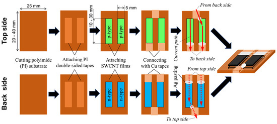
Figure 1.
Schematic diagram of the manufacturing process of DFTEGs.
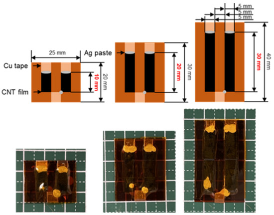
Figure 2.
Detailed dimensions of the DFTEGs and photographs of the completed DFTEGs.
3.3. Performance of DFTEGs with Different SWCNT Film Lengths
A system for measuring the performance of DFTEGs is shown in Figure 3. A DFTEG was attached to the outside of a 300 mL beaker. Two copper wires for voltage measurements and two thermocouples for temperature measurements at high and low temperatures on the sides were attached to the DFTEG, where the opposite sides of the copper wires and thermocouples were connected to a data logger (GL240, GRAPHTEC Co., Yokohama, Japan). Here, we assumed that the water temperature corresponded to that measured using the thermocouple attached to a DFTEG on the hot temperature side. Water at a temperature of 353 K was poured into the 300 mL beaker until the water level was at the center of the DFTEG, and the voltage and temperatures were measured sequentially while naturally cooling the water.
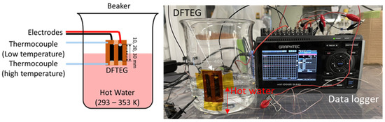
Figure 3.
Measurement system for the thermoelectric performance of DFTEG.
Figure 4 shows the performance of DFTEGs with different SWCNT film lengths. The relationship between the water temperature and temperature difference in DFTEGs is shown in Figure 4a. The temperature difference of DFTEGs for all film lengths increased with the increase in the water temperature. DFTEGs with longer film lengths exhibited a larger temperature difference than DFTEGs with shorter film lengths for the same water temperature owing to the low thermal conductivity of the polyimide substrate. When the water temperature was 348 K, the temperature differences at DFTEGs with film lengths of 10, 20, and 30 mm were 25, 31, and 39 K, respectively. In Figure 4b, the output voltage of DFTEGs increased linearly with the water temperature for all film lengths. The DFTEGs exhibited almost the same trend for all film lengths because all the DFTEGs were composed of p- and n-type SWCNT films fabricated with the same method and the same conditions. However, the maximum temperature difference was unique for each DFTEG; the DFTEG with a film length of 10 mm demonstrated a maximum temperature difference of 25 K, while that with a film length of 30 mm had a maximum temperature difference of 45 K. The DFTEGs with a length of 10 and 30 mm exhibited output voltages of 4.9 and 9.4, respectively, at their maximum temperature differences. Figure 4c shows the maximum power of DFTEGs as a function of the temperature difference. The maximum power Pmax is expressed as Pmax = Voc2/4Rtotal, where Voc and Rtotal represent the output voltage and measured total resistance of the DFTEGs, where the total resistance is the sum of the SWCNT film, electrode, and contact resistances. The total resistance of DFTEGs with film lengths of 10, 20, and 30 mm were 35, 46, and 65 Ω, respectively. The calculated contact resistance was 6.1 Ω/cm2 in all DFTEGs. The maximum power of DFTEGs increased quadratically for all film lengths when the temperature difference was increased. The maximum power of DFTEGs with film lengths of 10, 20, and 30 mm at a temperature difference of 25 K was 158, 137, and 66 nW, respectively. The maximum power of DFTEGs increased with a decreasing film length because of the decrease in the total resistance. Meanwhile, as the DFTEG with a 10 mm film length was less prone to temperature differences, the highest maximum power in the range of the water temperatures tested in this study was 324 nW, which was exhibited in DFTEGs with film lengths of 20 mm at a temperature difference of 35 K. To investigate the performance of DFTEGs in detail, the maximum power density, which was calculated by dividing the maximum power by the area of the SWCNT films, was estimated as shown in Figure 4d. The maximum power density exhibited a clearer difference in the film length compared to the maximum power. At a temperature difference of 25 K, the DFTEGs with film lengths of 10, 20, and 30 mm exhibited maximum power densities of 158, 69, and 22 nW/cm2, respectively; the highest power densities of the DFTEGs were 158 nW/cm2 at a temperature difference of 25 K, 162 nW/cm2 at a temperature difference of 35 K, and 82 nW/cm2 at a temperature difference of 45 K, respectively. When comparing the highest power densities of the DFTEGs with film lengths of 10 and 20 mm, the latter was approximately 3% higher than the former. However, considering that DFTEGs are often used in applications that are near 300 K, we concluded that the DFTEG with a 10 mm film length was the most suitable structural design.
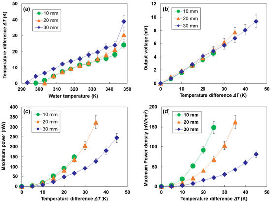
Figure 4.
Performance of DFTEGs with different SWCNT film lengths. (a) Relationship between the water temperature and temperature difference of DFTEGs. Relationship between the temperature difference and (b) output voltage, (c) maximum power, and (d) maximum power density.
3.4. Performance of DFTEGs Increased with p-n Pairs of SWCNT Films
To further increase the performance of DFTEGs, the number of p- and n-type SWCNT films was increased. The fabrication process was as described in Section 3.2. An image of the completed DFTEG is shown in Figure 5a. The DFTEG consisted of 15 p-n pairs of SWCNT films with 10 mm film lengths, and the polyimide substrate was 145 mm wide and 20 mm long. In Figure 5b, the output voltage of the DFTEG reached 40 mV at a temperature difference of 25 K, which was 8.2 times higher than that of the corresponding DFTEG with two p-n pairs, as shown in Figure 4b. Generally, the lowest voltage at which booster circuits can be used is 20 mV [42], which can be achieved by the DFTEG with an increased number of p-n pairs at a temperature difference of 15 K (water temperature = 333 K). Figure 5c shows the dependence of the maximum power on the temperature difference, where the total resistance of the DFTEG was 445 Ω. At a temperature difference of 25 K, the maximum power reached was 891 nW, which was 5.6 times higher than that of the corresponding DFTEG with two p-n pairs, as shown in Figure 4c. The factor by which the maximum power increased after the number of p-n pairs was increased (5.6 times) was less than that of the output voltage (8.2 times). This difference can be explained by the increase in contact resistance from 6.1 to 10.7 Ω/cm2. This issue should be solved to improve the manufacturing process in the next step.
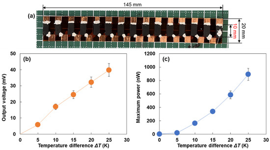
Figure 5.
Performance of DFTEGs with an optimized film length and increased number of p-n pairs. (a) Photograph of completed DFTEG. Relationship between the temperature difference and (b) output voltage and (c) maximum power.
We compared the maximum power of the DFTEGs with that of single-type flexible-film TEGs (p-n pair: four pairs, size: 20 mm wide and 25 mm length), which were fabricated using almost the same SWCNT films, as described in our previous report [40]. As single-type TEGs have four p-n pairs, we calculated the maximum power corresponding to the four p-n pairs in the DFTEGs. At a temperature difference of 25 K, the calculated maximum power of the DFTEGs was 238 nW, while that of the single-type flexible-film TEGs was 56 nW. Therefore, the performance of the flexible-film TEGs can be greatly enhanced using the dual-type design and optimized film length. The electric power produced by the optimized DFTEGs can operate IoT sensors with low power consumption, such as complementary metal–oxide semiconductor image [43] and ammonia vapor sensors [44]. To further improve the thermoelectric performance of DFTEGs for extending their applications, the total resistance should be reduced by increasing the electrical conductivity and thickness of SWCNT films [45,46], and the thermal conductivity must be reduced by enhancing phonon scattering in the SWCNT films [47,48].
4. Conclusions
We prepared DFTEGs using all-carbon nanotube films with different structural designs. A DFTEG was attached to the outside of a 300 mL beaker, and hot water was poured into the beaker until the water level was at the center of the DFTEG. The output voltage and temperatures were measured while the water cooled naturally. The highest output voltage was observed for DFTEGs with longer film lengths because temperature differences can be easily created within them. In contrast, the DFTEGs with shorter film lengths exhibited a higher maximum power due to their lower circuit resistance. To further increase the output voltage and maximum power, we prepared DFTEGs with a greater number of p-n pairs and short film lengths. The prepared DFTEG exhibited an output voltage of 40 mV and a maximum power of 891 nW at a temperature difference of 25 K. This maximum power of the DFTEG was 4.3 times higher than that of the single-type flexible-film TEGs. The obtained values of the DFTEG were sufficient to operate the IoT sensor with low power consumption. Therefore, we demonstrated an increase in the performance of TEGs owing to fabrication with the dual-type design and optimizing the structural designs; however, the performance of DFTEGs must be improved further to extend their applications. In the next step, the performance of DFTEGs should be improved. Feasible approaches are to decrease the electrical resistance of DFTEGs by increasing the film thickness and reduce the thermal conductivity of SWCNT films with controlling the film density.
Author Contributions
R.K. and M.T. conceptualized the idea and designed the experiments; R.K. fabricated the samples and characterized their thermoelectric properties and microstructures; R.K. analyzed the structural properties of the samples; R.K. and M.T. wrote the manuscript. All authors have read and agreed to the published version of the manuscript.
Funding
This study was supported by the business development of joint research in industry and academia at Hiratsuka city and Kanto Yakin Kogyo Corporation and Research Organization at Tokai University.
Institutional Review Board Statement
Not applicable.
Informed Consent Statement
Not applicable.
Data Availability Statement
The authors confirm that the data supporting the findings of this study are available within the article.
Acknowledgments
The authors would like to thank Zeon Corporation for providing SG-CNT powders.
Conflicts of Interest
The authors declare no conflict of interest.
References
- Chen, X.; Dai, W.; Wu, T.; Luo, W.; Yang, J.; Jiang, W.; Wang, L. Thin film thermoelectric materials: Classification, characterization, and potential for wearable applications. Coatings 2018, 8, 244. [Google Scholar] [CrossRef]
- Chen, Y.-S.; Lwo, B.-J. Large-area laying of soft textile power generators for the realization of body heat harvesting clothing. Coatings 2019, 9, 831. [Google Scholar] [CrossRef]
- Zaia, E.W.; Gordon, M.P.; Yuan, P.; Urban, J.J. Progress and perspective: Soft thermoelectric materials for wearable and internet-of-things applications. Adv. Electron. Mater. 2019, 5, 1800823. [Google Scholar] [CrossRef]
- Chen, B.; Kruse, M.; Xu, B.; Tutika, R.; Zheng, W.; Batlett, M.D.; Wu, Y.; Claussen, J.C. Flexible thermoelectric generators with inkjet-printed bismuth telluride nanowires and liquid metal contacts. Nanoscale 2019, 11, 5222–5230. [Google Scholar] [CrossRef]
- Inamoto, T.; Takashiri, M. Experimental and first-principles study of the electronic transport properties of strained Bi2Te3 thin films on a flexible substrate. J. Appl. Phys. 2016, 120, 125105. [Google Scholar] [CrossRef]
- Vieria, E.M.F.; Pires, A.L.; Silva, J.P.B.; Magalhães, V.H.; Grilo, J.; Brito, F.P.; Silva, M.F.; Pereira, A.M.; Goncalves, L.M. High-performance μ-thermoelectric device based on Bi2Te3/Sb2Te3 p–n junctions. ACS Appl. Mater. Interfaces 2019, 11, 38946–38954. [Google Scholar] [CrossRef]
- Sasaki, Y.; Takashiri, M. Effects of Cr interlayer thickness on adhesive, structural, and thermoelectric properties of antimony telluride thin films deposited by radio-frequency magnetron sputtering. Thin Solid Films 2016, 619, 195–201. [Google Scholar] [CrossRef]
- Morikawa, S.; Inamoto, T.; Takashiri, M. Thermoelectric properties of nanocrystalline Sb2Te3 thin films: Experimental evaluation and first-principles calculation, addressing effect of crystal grain size. Nanotechnology 2018, 29, 075701. [Google Scholar] [CrossRef]
- Matsuoka, K.; Okuhata, M.; Takashiri, M. Dual-bath electrodeposition of n-type Bi-Te/Bi-Se multilayer thin films. J. Alloys Compd. 2015, 649, 721–725. [Google Scholar] [CrossRef]
- Kudo, S.; Tanaka, S.; Miyazaki, K.; Nishi, Y.; Takashiri, M. Anisotropic analysis of nanocrystalline bismuth telluride thin films treated by homogeneous electron beam irradiation. Mater. Trans. 2017, 58, 513–519. [Google Scholar] [CrossRef]
- Takashiri, M.; Tanaka, S.; Hagino, H.; Miyazaki, K. Strain and grain size effects on thermal transport in highly-oriented nanocrystalline bismuth antimony telluride thin films. Int. J. Heat Mass Transfer. 2014, 76, 376–384. [Google Scholar] [CrossRef]
- Morgan, K.-A.; Tang, T.; Zeimpekis, I.; Ravagli, A.; Craig, C.; Yao, J.; Feng, Z.; Yarmolich, D.; Barker, C.; Assender, H.; et al. High-throughput physical vapour deposition flexible thermoelectric generators. Sci. Rep. 2019, 9, 4393. [Google Scholar] [CrossRef] [PubMed]
- Khumtong, T.; Sakulkalavek, A.; Sakdanuphab, R. Empirical modelling and optimization of pre-heat temperature and Ar flow rate using response surface methodology for stoichiometric Sb2Te3 thin films prepared by RF magnetron sputtering. J. Alloys Compd. 2017, 751, 65–72. [Google Scholar] [CrossRef]
- Kim, M.; Park, D.; Kim, J. A thermoelectric generator comprising selenium-doped bismuth telluride on flexible carbon cloth with n-type thermoelectric properties. Ceram. Int. 2022, 48, 10852–10861. [Google Scholar] [CrossRef]
- Yamamuro, H.; Hatsuta, N.; Wachi, M.; Takei, Y.; Takashiri, M. Combination of electrodeposition and transfer processes for flexible thin-film thermoelectric generators. Coatings 2018, 8, 22. [Google Scholar] [CrossRef]
- Jin, Q.; Shi, W.; Zhao, Y.; Qiao, J.; Qiu, J.; Sun, C.; Lei, H.; Tai, K.; Jiang, X. Cellulose fiber-based hierarchical porous bismuth telluride for high-performance flexible and tailorable thermoelectrics. ACS Appl. Mater. Interfaces 2018, 10, 1743–1751. [Google Scholar] [CrossRef]
- Yamamuro, H.; Takashiri, M. Power generation in slope-type thin-film thermoelectric generators by the simple contact of a heat source. Coating 2019, 9, 63. [Google Scholar] [CrossRef]
- Trung, N.H.; Toan, N.V.; Ono, T. Flexible thermoelectric power generator with Y-type structure using electrochemical deposition process. Appl. Energy 2018, 210, 467–476. [Google Scholar]
- Trung, N.H.; Toan, N.V.; Ono, T. Fabrication of π-type flexible thermoelectric generators using an electrochemical deposition method for thermal energy harvesting applications at room temperature. J. Micromech. Microeng. 2017, 27, 120006. [Google Scholar] [CrossRef]
- Kuang, N.; Zuo, Z.; Wang, W.; Liu, R.; Zhao, Z. Optimized thermoelectric properties and geometry parameters of annular thin-film thermoelectric generators using n-type Bi2Te2.7Se0.3 and p-type Bi0.5Sb1.5Te3 thin films for energy harvesting. Sens. Actuators A 2021, 332, 113030. [Google Scholar] [CrossRef]
- Chang, P.-S.; Liao, C.-N. Screen-printed flexible thermoelectric generator with directional heat collection design. J. Alloys Compd. 2020, 836, 155471. [Google Scholar] [CrossRef]
- Iijima, S.; Ichihashi, T. Single-shell carbon nanotubes of 1-nm diameter. Nature 1993, 363, 603–605. [Google Scholar] [CrossRef]
- Chiba, T.; Amma, Y.; Takashiri, M. Heat source free water floating carbon nanotube thermoelectric generators. Sci. Rep. 2021, 11, 14707. [Google Scholar] [CrossRef] [PubMed]
- Song, H.; Qiu, Y.; Wang, Y.; Cai, K.; Li, D.; Deng, Y.; He, J. Polymer/carbon nanotube composite materials for flexible thermoelectric power generator. Compos. Sci. Technol. 2017, 153, 71–83. [Google Scholar] [CrossRef]
- Ito, M.; Koizumi, T.; Kojima, H.; Saito, T.; Nakamura, M. From materials to device design of a thermoelectric fabric for wearable energy harvesters. J. Mater. Chem. A 2017, 5, 12068–12072. [Google Scholar] [CrossRef]
- MacLeod, B.A.; Stanton, N.J.; Gould, I.E.; Wesenberg, D.; Ihly, R.; Owczarczyk, Z.R.; Hurst, K.E.; Fewox, C.S.; Folmar, C.N.; Hughes, K.H.; et al. Large n- and p-type thermoelectric power factors from doped semiconducting single-walled carbon nanotube thin films. Energy Environ. Sci. 2017, 10, 2168–2179. [Google Scholar] [CrossRef]
- Komatsu, N.; Ichinose, Y.; Dewey, O.S.; Taylor, L.W.; Trafford, M.A.; Yomogida, Y.; Wehmeyer, G.; Pasquali, M.; Yanagi, K.; Kono, J. Macroscopic weavable fibers of carbon nanotubes with giant thermoelectric power factor. Nat. Commun. 2021, 12, 4931. [Google Scholar] [CrossRef] [PubMed]
- Nakai, Y.; Honda, K.; Yanagi, K.; Kataura, H.; Kato, T.; Yamamoto, T.; Maniwa, Y. Giant Seebeck coefficient in semiconducting single-wall carbon nanotube film. Appl. Phys. Express 2014, 7, 025103. [Google Scholar] [CrossRef]
- Piao, M.; Alam, M.-R.; Kim, G.; Dettlaff-Weglikowska, U.; Roth, S. Effect of chemical treatment on the thermoelectric properties of single walled carbon nanotube networks. Phys. Status Solidi B 2012, 249, 2353–2356. [Google Scholar] [CrossRef]
- Yonezawa, S.; Chiba, T.; Seki, Y.; Takashiri, M. Origin of n type properties in single wall carbon nanotube films with anionic surfactants investigated by experimental and theoretical analyses. Sci. Rep. 2021, 11, 5758. [Google Scholar] [CrossRef]
- Nonoguchi, Y.; Nakano, M.; Murayama, T.; Hagino, H.; Hama, S.; Miyazaki, K.; Matsubara, R.; Nakamura, M.; Kawai, T. Simple salt-coordinated n-type nanocarbon materials stable in air. Adv. Funct. Mater. 2016, 26, 3021–3028. [Google Scholar] [CrossRef]
- Nakashima, Y.; Yamaguchi, R.; Toshimitsu, F.; Matsumoto, M.; Borah, A.; Staykov, A.; Islam, M.-S.; Hayami, S.; Fujigaya, T. Air-stable n-type single-walled carbon nanotubes doped with benzimidazole derivatives for thermoelectric conversion and their air-stable mechanism. ACS Appl. Nano Mater. 2019, 2, 4703–4710. [Google Scholar] [CrossRef]
- Horike, S.; Wei, Q.; Akaike, K.; Kirihara, K.; Mukaida, M.; Koshiba, Y.; Ishida, K. Bicyclic-ring base doping induces n-type conduction in carbon nanotubes with outstanding thermal stability in air. Nat. Commun. 2022, 13, 3517. [Google Scholar] [CrossRef]
- Seki, Y.; Nagata, K.; Takashiri, M. Facile preparation of air-stable n-type thermoelectric single-wall carbon nanotube films with anionic surfactants. Sci. Rep. 2020, 10, 8104. [Google Scholar] [CrossRef]
- Yonezawa, S.; Amma, Y.; Miura, K.; Chiba, T.; Takashiri, M. Air stability of n-type single-walled carbon nanotube films with anionic surfactants investigated using molecular dynamics. Colloids Surf. A 2021, 625, 126925. [Google Scholar] [CrossRef]
- Takashiri, M.; Shirakawa, T.; Miyazaki, K.; Tukamoto, H. Fabrication and characterization of bismuth–telluride-based alloy thin film thermoelectric generators by flash evaporation method. Sens. Actuators A 2007, 138, 329–334. [Google Scholar] [CrossRef]
- Takayama, K.; Takashiri, M. Multi-layered-stack thermoelectric generators using p-type Sb2Te3 and n-type Bi2Te3 thin films by radio-frequency magnetron sputtering. Vacuum 2017, 114, 164–171. [Google Scholar] [CrossRef]
- Hata, K.; Futaba, D.N.; Mizuno, K.; Namai, T.; Yumura, M.; Iijima, S. Water-assisted highly efficient synthesis of impurity-free single-walled carbon nanotubes. Science 2004, 306, 1362–1364. [Google Scholar] [CrossRef]
- Kurokawa, T.; Mori, R.; Norimasa, O.; Chiba, T.; Eguchi, R.; Takashiri, M. Influences of substrate types and heat treatment conditions on structural and thermoelectric properties of nanocrystalline Bi2Te3 thin films formed by DC magnetron sputtering. Vacuum 2020, 179, 109535. [Google Scholar] [CrossRef]
- Amma, Y.; Miura, K.; Nagata, S.; Nishi, T.; Miyake, S.; Miyazaki, K.; Takashiri, M. Ultra-long air-stability of n-type carbon nanotube films with low thermal conductivity and all-carbon thermoelectric generators. Sci. Rep. 2022, 12, 21603. [Google Scholar] [CrossRef]
- Kobayashi, A.; Konagaya, R.; Tanaka, S.; Takashiri, M. Optimized structure of tubular thermoelectric generators using n-type Bi2Te3 and p-type Sb2Te3 thin films on flexible substrate for energy harvesting. Sens. Actuators A 2020, 313, 112199. [Google Scholar] [CrossRef]
- Carison, E.J.; Strunz, K.; Otis, B.P. A 20 mV input boost converter with efficient digital control for thermoelectric energy harvesting. IEEE J. Solid-State Circuits 2010, 45, 741–750. [Google Scholar] [CrossRef]
- Hanson, S.; Seok, M.; Lin, Y.-S.; Foo, Z.; Kim, D.; Lee, Y.; Liu, N.; Sylvester, D.; Blaauw, D. A low-voltage processor for sensing applications with picowatt standby mode. IEEE J. Solid-State Circuits 2009, 44, 1145–1155. [Google Scholar] [CrossRef]
- Feng, L.; Tang, W.; Zhao, J.; Yang, R.; Hu, W.; Li, Q.; Wang, R.; Guo, X. Unencapsulated air-stable organic field effect transistor by all solution processes for low power vapor sensing. Sci. Rep. 2016, 6, 20671. [Google Scholar] [CrossRef]
- Seki, Y.; Takashiri, M. Freestanding bilayers of drop-cast single-walled carbon nanotubes and electropolymerized poly(3,4-ethylenedioxythiophene) for thermoelectric energy harvesting. Org. Electron. 2020, 76, 105478. [Google Scholar] [CrossRef]
- Yabuki, H.; Yonezawa, S.; Eguchi, R.; Takashiri, M. Flexible thermoelectric films formed using integrated nanocomposites with single-wall carbon nanotubes and Bi2Te3 nanoplates via solvothermal synthesis. Sci. Rep. 2020, 10, 17031. [Google Scholar] [CrossRef]
- Hida, S.; Hori, T.; Shiga, T.; Elliott, J.; Shiomi, J. Thermal resistance and phonon scattering at the interface between carbon nanotube and amorphous polyethylene. Int. J. Heat Mass Transfer. 2013, 67, 1024–1029. [Google Scholar] [CrossRef]
- Sun, K.; Stroscio, M.A.; Dutta, M. Thermal conductivity of carbon nanotubes. J. Appl. Phys. 2009, 105, 074316. [Google Scholar] [CrossRef]


Disclaimer/Publisher’s Note: The statements, opinions and data contained in all publications are solely those of the individual author(s) and contributor(s) and not of MDPI and/or the editor(s). MDPI and/or the editor(s) disclaim responsibility for any injury to people or property resulting from any ideas, methods, instructions or products referred to in the content. |
© 2023 by the authors. Licensee MDPI, Basel, Switzerland. This article is an open access article distributed under the terms and conditions of the Creative Commons Attribution (CC BY) license (https://creativecommons.org/licenses/by/4.0/).