Article

Tailoring the Structural, Optical and Electrical Properties of Zinc Oxide Nanostructures by Zirconium Doping

1
Institute of Physics, Baghdad ul Jadeed Campus, The Islamia University of Bahawalpur, Bahawalpur 63100, Pakistan
2
Department of Chemistry, Baghdad ul Jadeed Campus, The Islamia University of Bahawalpur, Bahawalpur 63100, Pakistan
3
Institute of Energy and Climate Research, Materials Synthesis and Processing (IEK-1), Forschungszentrum Jülich GmbH, 52425 Jülich, Germany
4
Department of Business Administration, College of Business Administration, Princess Nourah bint Abdulrahman University, P.O. Box 84428, Riyadh 11671, Saudi Arabia
5
Medical Physics Department, Al-Mustaqbal University College, Babylon 51001, Iraq
6
Department of Mechanical Engineering, CEMMPRE, Centre for Mechanical Engineering Materials and Processes, University of Coimbra, Rua Luís Reis Santos, 3030-788 Coimbra, Portugal
7
Department of Physics, Riphah International University Faisalabad, Faisalabad 38000, Pakistan
*
Authors to whom correspondence should be addressed.
Coatings 2023, 13(1), 34; https://doi.org/10.3390/coatings13010034
Submission received: 30 November 2022 / Revised: 19 December 2022 / Accepted: 21 December 2022 / Published: 25 December 2022
(This article belongs to the Special Issue Trends in Coatings and Surface Technology)

Abstract

:
Owing to its low resistivity, high transmittance, and tunable optical band gap, ZnO is of great interest for optoelectronic applications. Herein, the sol–gel technique was used to synthesize un-doped and zirconium-doped zinc oxide (ZZO) nanostructures with different concentrations of Zirconium (Zr). X-ray diffraction (XRD), scanning electron microscope (SEM), Raman spectroscopy, Fourier transform infrared spectroscopy (FTIR), UV-Vis spectroscopy, and photoluminescence (PL) measurements were used to investigate the influence of Zr doping on the structural, optical, and electrical properties of developed nanostructures. XRD and SEM confirmed the increase in crystallite size with increasing concentrations of Zr. Raman analysis indicated the presence of oxygen vacancies in synthesized nanostructures. UV-Vis spectroscopy illustrated the blue shift of band gap and red shift of the absorption edge for ZZO nanostructures with increasing concentrations of Zr. For the measurement of electrical properties, the spin-coating technique was used to deposit un-doped and Zr-doped ZnO layers of ~165 nm thickness. The four-probe-point (4PP) method illustrated that the doping of Zr caused a reduction in electrical resistance. Hall Effect measurements showed a high value, 3.78 × 1020 cm−3, of the carrier concentration and a low value, 10.2 cm2/Vs, of the carrier mobility for the Zr-doped layer. The high optical transmittance of ~80%, wide band gap of 3.51 eV, low electrical resistivity of 1.35 × 10⁻³ Ω·cm, and maximum carrier concentration of 3.78 × 1020 cm−3 make ZZO nanostructures one of the most promising candidates for the application of transparent conductive oxide (TCO) in optoelectronic devices.

1. Introduction

Tin-doped indium oxide (ITO) has high optical transmittance, high work function, and electrical conductivity [1]. These superior properties make the ITO nanostructures the most widely used transparent conductive oxide (TCO) in photovoltaic cells [2,3], light-emitting diodes (LEDs) [4], thin film transistors (TFTs) [5,6], and liquid crystal displays [7,8], etc. Recently, the demand of TCOs materials for optoelectronic applications has been increasing and a stable supply of ITO is insufficient to fulfil the need of this age because indium (In) is a very expensive and rare element; this deposition of ITO nanostructures is therefore very expensive and takes place at high temperatures [9]. It opens the way for researchers to find cost-effective and abundant materials for the applications of TCOs. The n-type semiconductor zinc oxide (ZnO) was actively investigated and it has pivotal technological and fundamental importance due to high optical transmittance, low electrical resistance, abundance in the earth, high radiation resistance, and low toxicity [5]. Its optoelectronic properties can be tuned by doping of various metals. It is used as TCO in a variety of technological domains such as laser diodes [10,11], thin film transistors (TFT) [12], dye-sensitized solar cells (DSSC) [13], light-emitting diodes (LEDs) [14,15] and transparent conductive oxides (TCOs) [16]. Solar cells [17,18], organic light-emitting diodes (OLED) [19] and flat-panel displays [20]. The doping of suitable metallic elements can enhance the optical transmittance and electrical conductivity of ZnO, making it a more favorable material for TCO applications. To compete with ITO, metal-doped ZnO must have electrical resistivity ≤ 10−3, optical transmittance > 80% and, >3.37 eV wide energy for TCO application [21]. To achieve these properties, dopants should provide extra ionized electrons. A variety of dopants such as Sn [22], B [23,24], In [25,26], Co [27], Ge [28], Hf [29], Zr [30], Al [31,32], Ga [33,34], Fe [35], and Fe+Al [36] have been reported to improve the properties of ZnO as a TCO material. Especially, Zr doping in ZnO has a greater impact on its crystallite size, size shape, bandgap, and sensing. Zr is an n-type impurity, while Zr+4 an Zn+2 have an approximately different ionic radius of 0.84 and 0.74 Å respectively, the ionic radius of Zr+4 is larger than that of Zn+2 [30,37]. Therefore, Zr-doped ZnO is anticipated to have improved properties, though the function of Zr dopant in the optoelectronic industry is not well-established. Semiconductor Zr-doped ZnO (ZZO) nanostructures have a high optical transmittance, low electrical resistance, and wide bandgap, and all these properties make ZZO nanostructures potential candidates as a TCO for photovoltaic devices and organic light-emitting devices [30]. In this research, we synthesized highly optical transparent and electrically conductive Zr-doped ZnO nanostructures by sol–gel and spin-coating techniques, and studied the effect of Zr doping on the structural, optical, and electrical properties of ZZO nanostructures. This study highlighted promising conductive and transparent properties of the deposited nanostructures for optoelectronic applications.
A ZnO semiconductor with different dimensions (1D, 2D, and 3D) and morphologies can be synthesized by vapor liquid–solid process [38], the precipitation method [39], RF magnetron sputtering [40,41,42], low-temperature coprecipitation method [43], atomic layer deposition [32,34], pulsed laser deposition [44], sol–gel method [45], and water oxidation [46], etc. ZnO-based thin films are well reputed, having the ability to improve cell vitality; such coatings are fabricated using solution-based techniques such as the hydrothermal method and chemical bath deposition (CBD) [47,48]. Among all these methods, the sol–gel method is highly preferred because of easy processing, high homogeneity, controlled porosity, and cost effectiveness. In the sol–gel method, it is highly possible to control the microstructure of deposited nanostructures [49]. Paul et al. synthesized zirconium-doped ZnO films with different Zr concentrations and studied the post annealing effect. They reported the electrical resistivity as being as low as ~7.2 × 10⁻³ Ω cm for 1.5 at.% ZrO2 and the maximum optical band gap as 3.287 eV for 3 at.% ZrO2 [50].

2. Materials and Methods

2.1. Synthesis of Un-Doped and Zr-Doped ZnO (ZZO) Nanopartciles

All the chemical reagents were purchased from Sigma Aldrich (St. Louis, Missouri, WI, USA) without further purification. ZrxZn1−xO (ZZO-A for x = 0.00, ZZO-B for x = 0.015, ZZO-C for x = 0.03 and ZZO-D for x = 0.045) nanophase compounds were successfully fabricated by cost-effective nitrate precursor-based sol–gel technique. High purity zinc nitrate hexahydrate (Zn(NO3)3·6H2O, 99%) and zirconyl nitrate monohydrate (ZrO(NO3)2·H2O, 99%) were used as initial ingredients. The precursor solution was prepared by dissolving stoichiometric amounts of Zn(NO3)3·6H2O and ZrO(NO3)2·H2O in double-distilled water. When both precursors fully dissolved in solvent, regulated quantities of urea (NH2CONH2, 98%) were added, but we made sure that the molar ratio was 1:1 for precursors and urea. Sodium hydroxide (NAOH, 97%) was added to the solution in small amount to adjust the pH around 7. On the hot plate with continuous stirring solution was heated to 140 °C. Stirring and heating processes continued at 140 °C until a gel was formed. The formed gel was dried at 200 °C in an open environment. The resulted dried powder was grinded for 20 min and annealed at 400 °C for 4 h to improve the phase ordering.

2.2. Deposition of Un-Doped and Zr-Doped ZnO (ZZO) Films

For the measurement of electrical properties, the spin-coating technique was used to deposit ~165 nm ZZO layers on commercial glass substrates. Commercial glass substrates were washed with ethylene glycol (C2H6O2, 99.8%). Substrates were placed on the spin-coater and the formed gel added drop-by-drop on the surface of substrates in such a way that the gel entirely covered the surface; the speed of the coater was maintained at 3000 rpm throughout the coating process. Coated samples (ZZO-A for x = 0.00, ZZO-B for x = 0.015, ZZO-C for x = 0.03 and ZZO-D for x = 0.045) were placed in a muffle furnace at 150 °C for 20 min to obtain the homogenous layers; at the end, deposited layers were cooled down at room temperature and prepared for the characterizations.

2.3. Characterization Tools

Structural properties of the synthesized nanostructures were carried out by using Bruker d8, Cu-Kα (1.54 Å) X-ray diffraction (XRD) (Bruker, Billerica, MA, USA). The morphology of the nanostructures was collected by Hitachi SU-70 scanning electron microscope (SEM) (Hitachi, Tokyo, Japan). Raman analysis was detected by using Horiba RAM-HR800 microscope (Horiba, Kyoto, Japan). Photoluminescence (PL) measurements were performed by using Horiba RAM-HR800 microscope fitted with HE-Cd UV laser (20 mW power, 325 nm) (Horiba, Kyoto, Japan). Optical properties were studied by using SHIMADZU Solidspec-3700DUV dual beam spectrophotometer (Shimadzu, Kyoto, Japan). FTIR analysis carried out by using spectrum 2, Perkin Elmer (Waltham, MA, USA). The electrical resistance of the deposited nano layers measured by locally built four-probe point (4PP) system. NANO-CHIP Reliability Grade Hall Effect system was used to measure the carrier concentration and carrier mobility of deposited nano layers.
Structural, morphological and FTIR analysis were experimentally performed in Central Hi-Tech Lab (CHL), Government College University Faisalabad (GCUF), Pakistan. The Raman analysis, Photoluminescence (PL) measurements, optical and electrical properties of the nanostructures were experimentally performed in Centre for Advanced Electronics and Photovoltaic Engineering (CAEPE), International Islamic University Islamabad (IIUI), Pakistan.

3. Results and Discussion

3.1. XRD Analysis

The crystal structures of ZZO films were examined by using XRD patterns. Figure 1 shows the XRD patterns of un-doped (ZZO-A) and Zr-doped ZnO (ZZO-B, ZZO-C and ZZO-D) samples. The identification of all diffraction peaks (100), (002), (101), (102), (110), (103), (112) and (202) confirmed that the deposited nanostructures ZZO films had hexagonal wurtzite structures compared with JCPDS card No. 01-1136. No extra peaks related to Zr and its oxides were observed, indicating that Zr did not alter the wurtzite structure of ZnO. However, doping of Zr in ZnO caused the expansion in lattice parameters and also caused the increment in crystallite size [39]. Crystallite size “D” lattice parameters “a”, “c”, micro strain “ε”, volume of unit cell “V” and bond length (Zn-O) “L” were calculated by using the following equations [30,51,52].
D = k λ β cos θ
1 d 2 = 4 3 [ h 2 + h k + k 2 a 2 ] + [ l 2 c 2 ]
ε = β cos θ 4
V = 3 a 2 c 2
L = a 2 3 + ( 0.5 u ) 2 c 2
u = a 2 3 c 2 + 0.25
where K is a dimensionless constant with value 0.9 to 1.0, λ represents the wavelength (Cu-Kα radiation, 1.5406 Å), β symbolizes full width half maximum (FWHM) in radians, θ signifies the angle of diffraction, and u is the internal relaxation parameter.
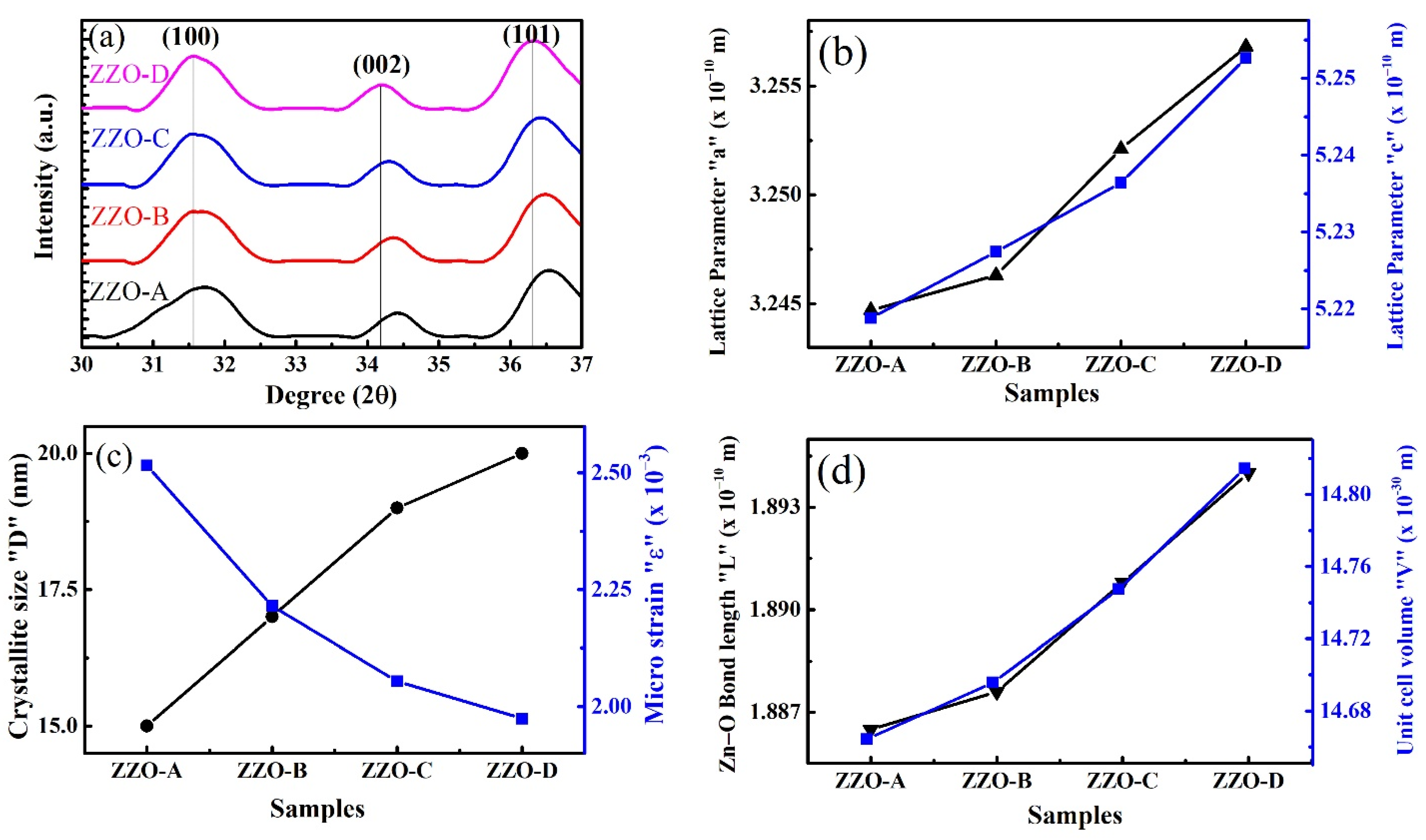
The values of structural parameters as a function of Zr concentration are given in Table 1. Figure 2a shows the shift of (100), (002), and (101) peaks towards the smaller values of 2θ with increasing concentration of Zr. Figure 2b shows the relationship of the lattice constants “a” and “c” with the increasing Zr concentration. Both “a” and “c” increased linearly with increasing Zr concentration, due to incorporation of Zr ions into ZnO lattice and lattice defects. Moreover, the increase in crystallite size and increased in lattice constants may be due to the difference of ionic radii of Zn2+ (0.074 nm) and Zr4+ (0.084 nm) [40,51]. The defects such as free charges, oxygen vacancies, and Zn interstitials are responsible for the increase in lattice parameters [40]. Micro strain “ε” was decreased. Consequently, the crystallite size “D” increases from ~15.1 to 20.3 nm as shown in Figure 2c. Zr+ ions trapped in non-equilibrium sites. When these ions shifted towards equilibrium sites caused the decrease in micro strain “ε” [39]. As the doping concentration of Zr increased, the number of trapped Zr+ ions also increased in non-equilibrium sites. Subsequently, the “ε” decreased from 2.52 × 10⁻³ to 1.97 × 10⁻³. Unit cell volume “V” of ZZO nanostructures increases with increasing concentration of Zr from 14.66 to 14.81 Å3. The measured bond length between oxygen and zirconium atom (Zn-O) are in range of 1.88 to 1.89 Å, which are in the good agreement with the reported values by C. Supatutkul, et al. [53].
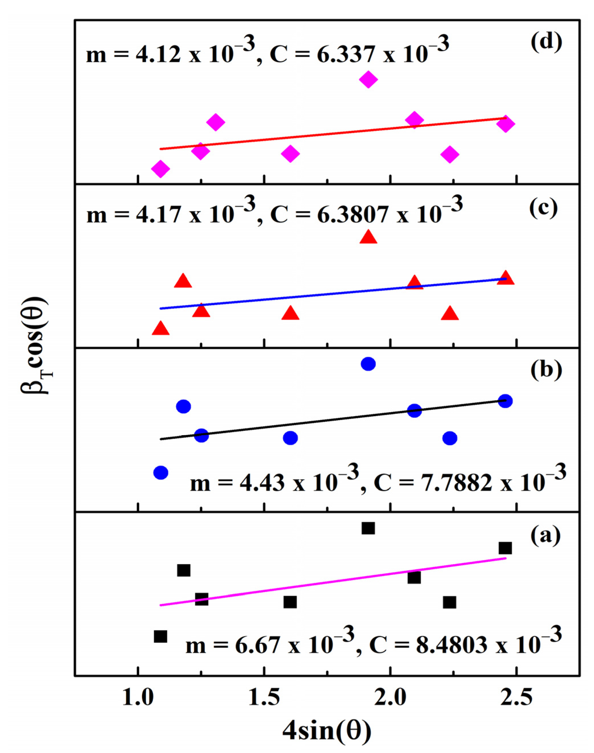
The micro strain (ε) and crystallite size (D) for all synthesized nanoparticles were further calculated by the W-H method, using, β T cos ( θ ) as a function of 4 sin ( θ ) as shown in Figure 3. The β T cos ( θ ) axis intercept “C” was used to calculate the crystallite size by using equation C = K λ D and the straight-line slope “m” provides the micro strain [52]; the calculated values of the crystallite size and micro strain by the W-H plot are shown in Table 1.

3.2. Raman Analysis

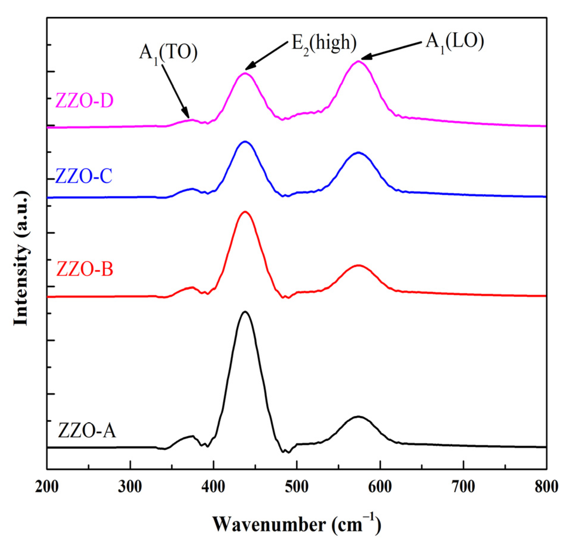
Raman spectroscopy is a most promising nondestructive technique which gives detailed information about crystallinity, phase, polymorph, molecular interactions, and chemical structure. Its basic phenomenon is the interaction of light with existing chemical bonds within materials [54]. To investigate the presence of defects and vibrational properties of ZZO nanostructures, a room-temperature Raman scattering experiment was carried out with a 325 nm excitation laser line. The room temperature Raman spectra of deposited nanostructures were comparably plotted in the range of 200 to 800 cm−1, as shown in Figure 4. A single longitudinal optical (LO) phonon with A1 symmetry was well resolved at 574 cm−1 in all samples. This LO phonon mode originated at 574 cm−1 and is due to defects such as Zn interstitials, oxygen vacancies, and their complexes [55]. In the Raman spectra at 438 cm−1, the strong occurrence of E2(high) modes was also observed and this can be the Raman shift for ZnO [56,57] specifically due to the vibrations of its oxygen atoms [58]. The transverse optical mode A1(TO) was also observed at 378 cm−1 in the developed nanostructures, but the intensity of A1(TO) and E2(high) modes reduced with increasing concentrations of Zr, while the intensity of the optical phonon mode A1(LO) increased with increasing concentrations of Zr.

3.3. FTIR Analysis

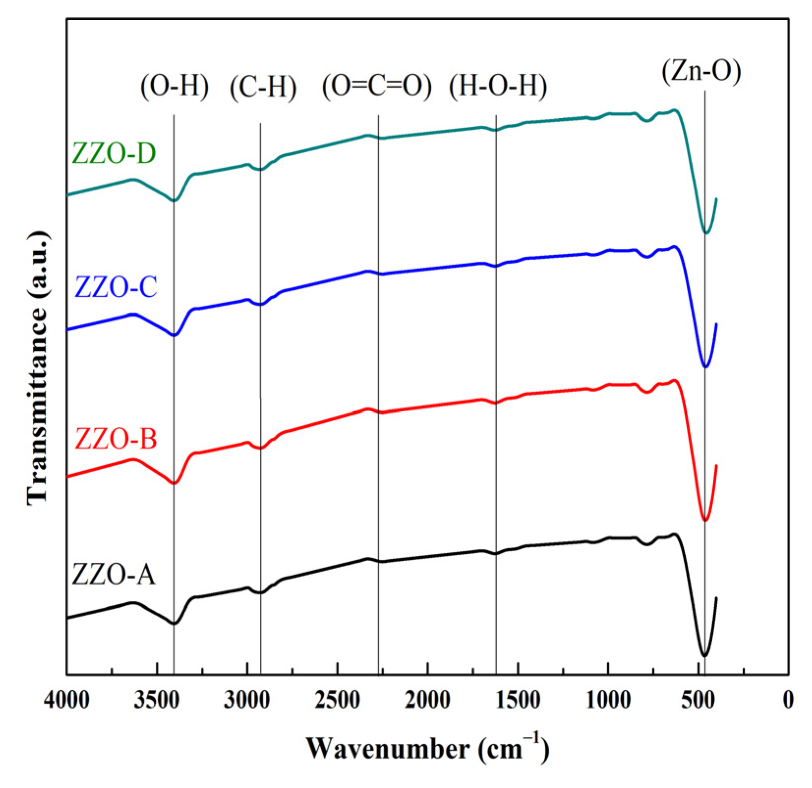
The chemical structure of the deposited nanostructures was investigated by FTIR spectroscopy; Figure 5 shows the FTIR spectra of ZZO-A, ZZO-B, ZZO-C, and ZZO-D samples. O-H stretching vibration of H2O was observed at the 3421–3440 cm−1 absorption band [59]. At 2832–2842, 2920–2922, and 2340–2342 cm−1 the absorption bands correspond to the C-H stretching mode [60,61] and the existence of CO2 molecules, respectively [52]. A bending vibration of H-O-H was observed at 1623–1632 cm−1 by a sharp absorption band [62]. The band observed at 465 cm−1 is due to Zn-O bonding [53]. The bands observed at 759–764 and 1032–1044 cm−1 are due to precursors [63]. For sample ZZO-A, the Zn-O bond at 465 cm−1 is associated with stretching frequency, which is observed to 460, 458, and 453 cm−1 for ZZO-B, ZZO-C and ZZO-D, respectively. However, the Zn-O absorption band showed a minor shift with increasing concentrations of Zr, which may be due to the change in bond length after replacement of Zn with Zr, which is correlated with the bond length Zn-O shown in Table 1, which increases from 1.88 to 1.89 Å with increasing Zr content. As Zn is slightly lighter than Zr, the substitution causes a downward shift due to the basic optical transverse phonon mode associated with theories of vibrations of mixed crystals [64].

3.4. SEM and EDX Analysis

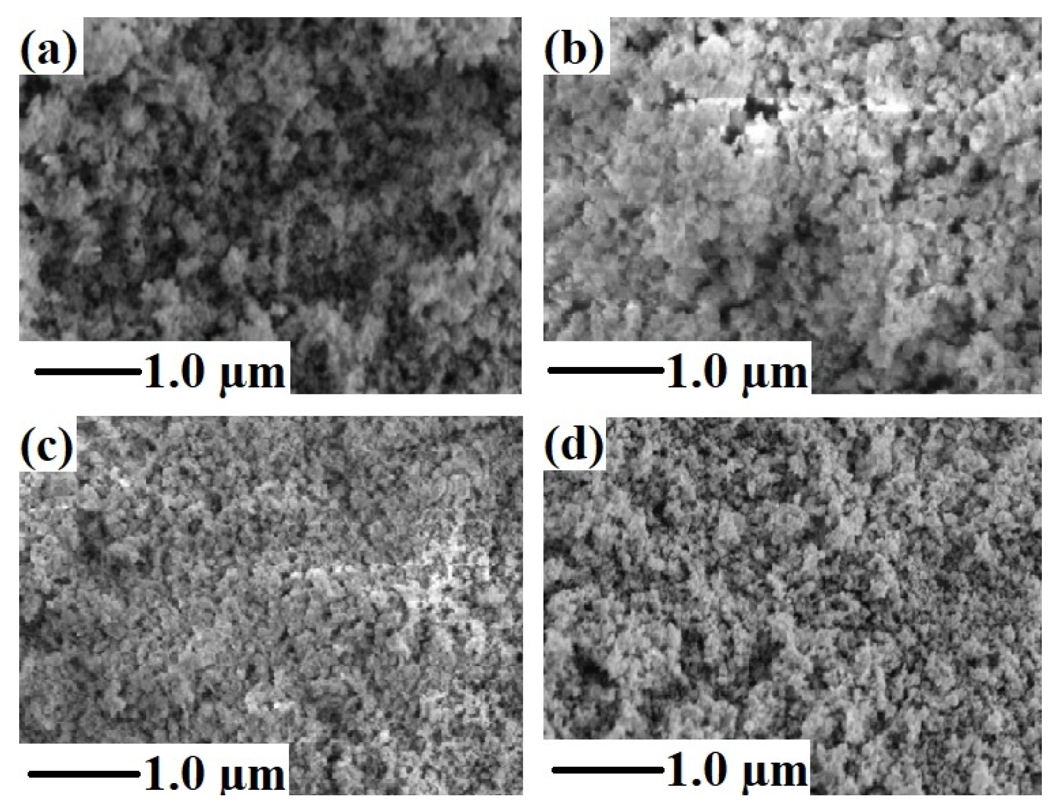
The SEM micrographs of ZZO-A, ZZO-B, ZZO-C, and ZZO-D are shown in Figure 6. All the nanostructures showed a uniform surface morphology with irregular shapes of evenly distributed grains. All four samples exhibited agglomeration because the force of attraction between nanostructures increases with increasing the surface area to volume ratio. The addition of Zr in ZnO lattice may be the cause of agglomeration of nanostructures. SEM micrographs revealed that the particles distributed homogenously throughout the samples.
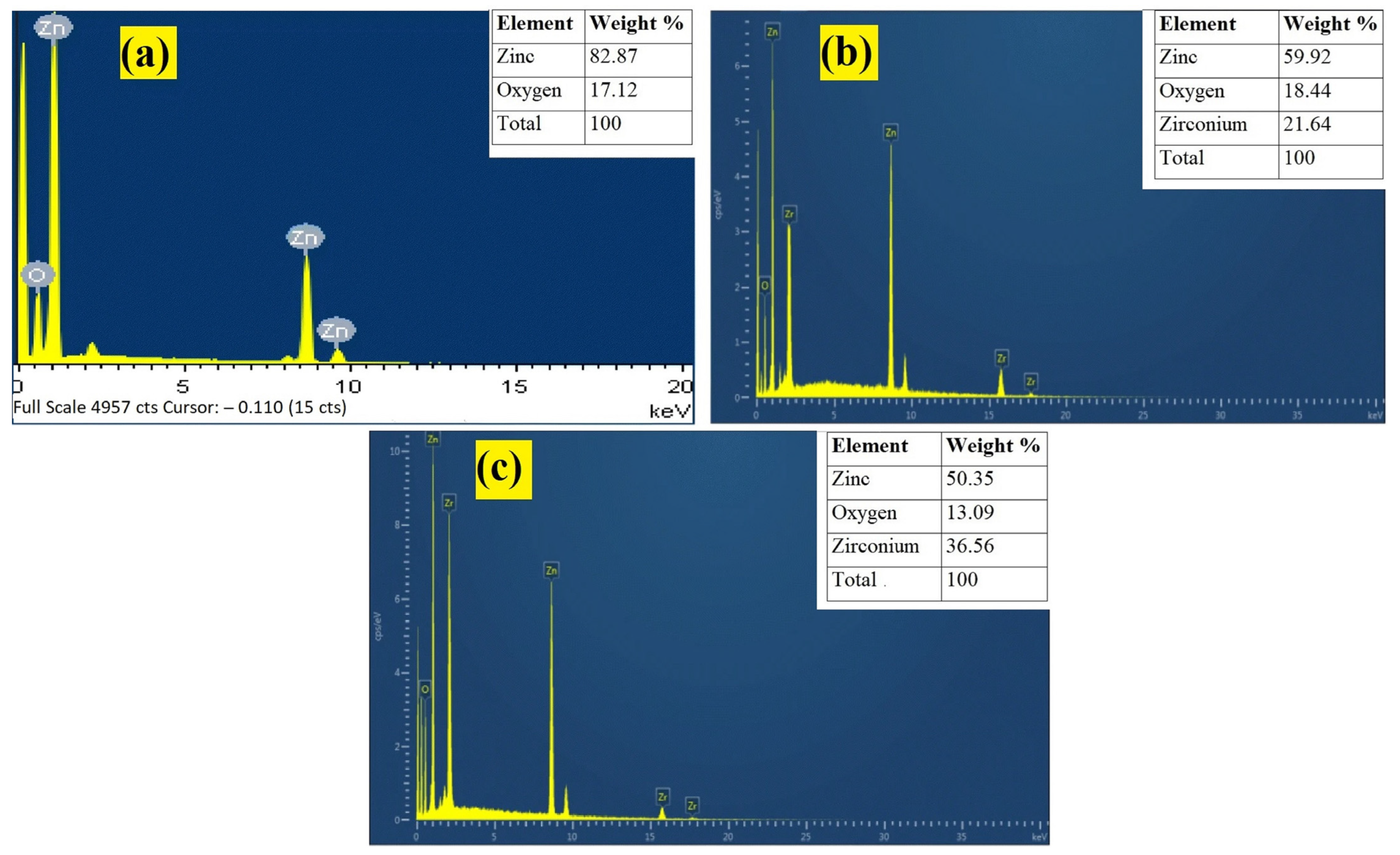
The EDX analysis of undoped ZnO (ZZO-A) and Zr-doped ZnO (ZZO-C, ZZO-D) nanostructures are shown in Figure 7. The EDX analysis of ZnO exhibited the elemental peaks of O and Zn [65]. The ZZO-C and ZZO-D nanostructures exhibited the same elemental peaks in addition to Zr peaks. The results exhibited that the nanostructures are composed only of the respective atoms without any impurity. Thus, the EDX analysis revealed the elemental composition of the synthesized nanostructures.

3.5. Optical Analysis

3.5.1. UV-Vis Spectroscopy

The optical transmittance of ZZO-A, ZZO-B, ZZO-C, and ZZO-D nanostructures in the wavelength range of 300 to 2500 nm is shown in Figure 8. All the samples showed high (>81%) optical transmittance at 380–2000 nm. Optical transmittance of deposited ZZO nanostructures decreases after wavelength ~1600 nm due to the variations in plasma frequency. There is a direct relationship between plasma frequency and carrier density. If the plasma frequency increases, the electrical conductivity of nanostructures increases. The samples ZZO-C and ZZO-D showed average optical transmittances ~80%, which is greater than the transmittance of sample ZZO-A ~75%. The average optical transmittance is related to the optical band gap. The optical band gap increases, according to the Burstein–Moss effect in which band filling effects cause a higher carrier density as the optical absorption reduces.
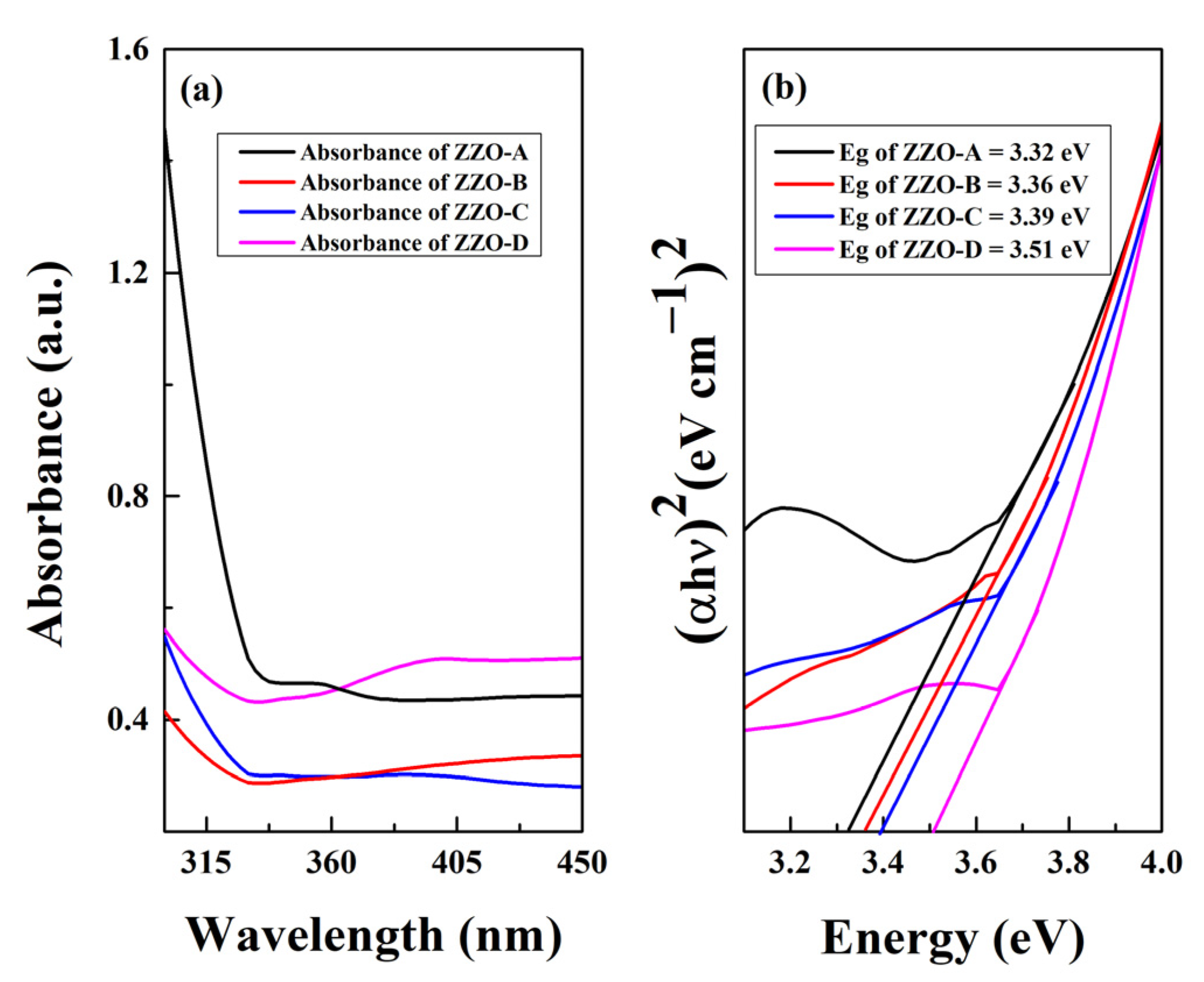
The optical band gap of all the samples was estimated by Tauc’s relationship. The extrapolating of the linear portion of hʋ versus (αhʋ)2 curve provides the optical band gap of samples [66].
α h ʋ = A ( h ʋ E g ) n
where A is a band-tailing parameter, slope of the Tauc line, n values depending on the transition probability, 2 for the direct allowed band gap, (eV) is the photon energy, α is the absorption coefficient, and Eg is the optical band gap of the material. The optical band gap of the developed nanostructures increased from 3.32 for ZZO-A to 3.51 eV for ZZO-D, shown in Figure 9b. The increment in the optical bad gap explained by the change in lattice parameters was caused by the doping. It was illustrated that the increase in lattice parameters caused an improvement in optical band gap [67]. The doping of Zr increases the band gap of ZnO, which is related to the reported study that doping of Zr causes the increase in grain size [43] that is correlated from XRD, SEM analysis. The improvement in optical band gap is associated with the Burstein–Moss effect because this shift is confirmed by PL measurements (mentioned in the next section).

3.5.2. PL Analysis

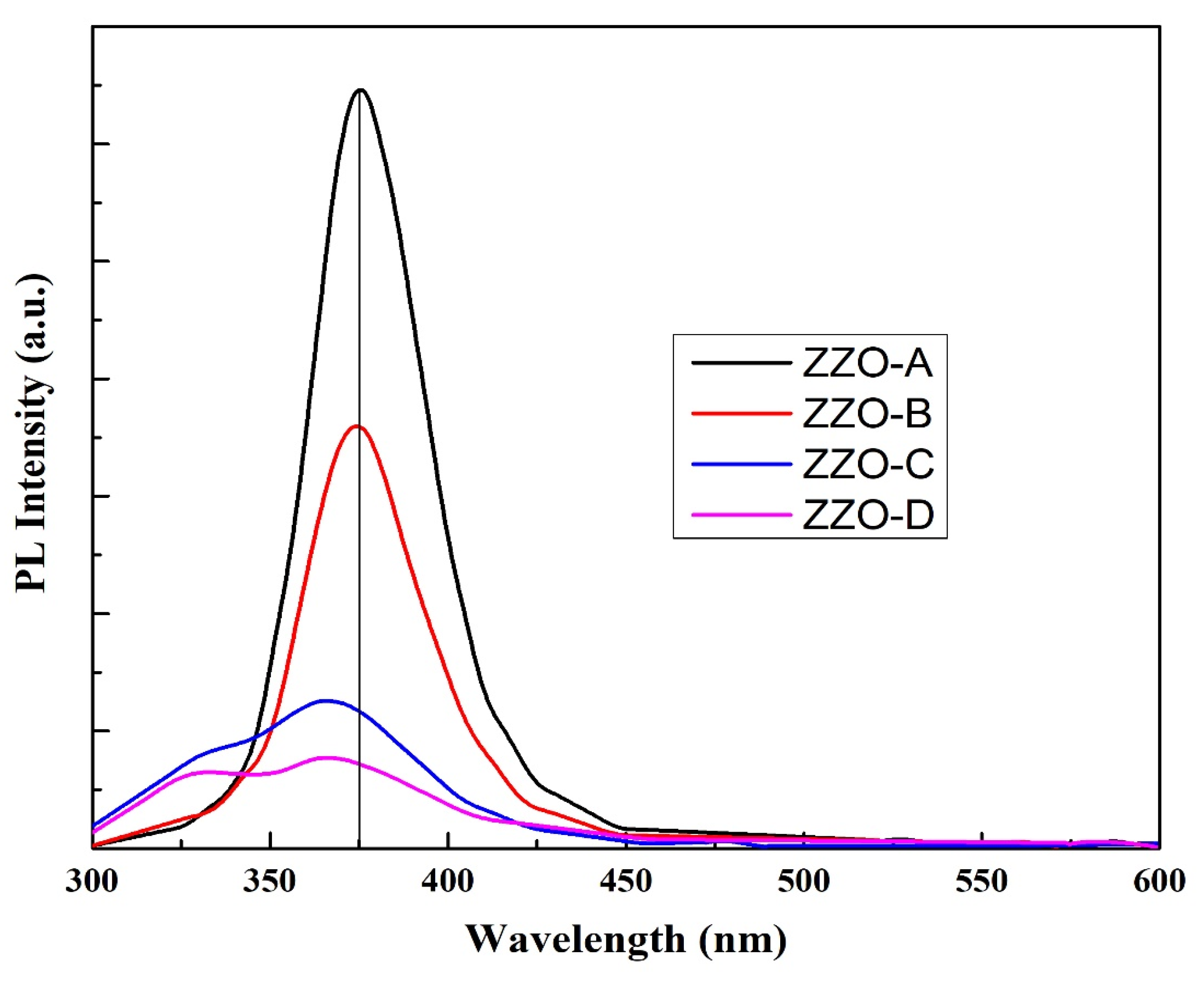
Photoluminescence (PL) spectroscopy is a nondestructive and non-contact method of probing materials. PL is photon or white light energy which stimulates the emission of photon from any matter [68]. The PL spectra of Zr-doped ZnO nanostructures at room temperature with different concentrations of Zr are plotted in Figure 10. As the doping of Zr concentration increased, the near band edge (NBE) emission decreased from 376 to 365 nm. The carrier charge mobility decreased with increasing concentrations of Zr. The increase in carrier mobility caused the scattering of electrons which changed the emission shift from longer to shorter wavelengths.
The samples ZZO-C and ZZO-D exhibited two low energy emission peaks at ~367 and 365 nm and high energy emission peaks at ~330 and 327 nm, respectively. The pair of such a low energy emission peak and high energy emission peak may be due to the recombination of different two states. The phenomenon of peak separation due to these two peaks was observed. Magnetic fields caused Zeeman effects, which produced peak separation [69] various exciton recombinations were also observed when measurements were carried out at low temperatures [21]. However, in our work there was no one magnetic or electric field and the measurements were carried out at room temperature, so the first dominant peaks (330 nm, 327 nm) corresponded to electron hole plasma (EHP) emission states [21,70] and the band-to-band recombination of energy increased up to 367 nm for ZZO-C and 365 nm for ZZO-D due to the Burstein–Moss effect.

3.6. Electrical Analysis

The four-point probe (4PP) method was used to measure the electrical resistance of deposited ~165 nm-thick nano layers by using the following equations [60].
R = ρ T
ρ = π ln ( 2 ) V I
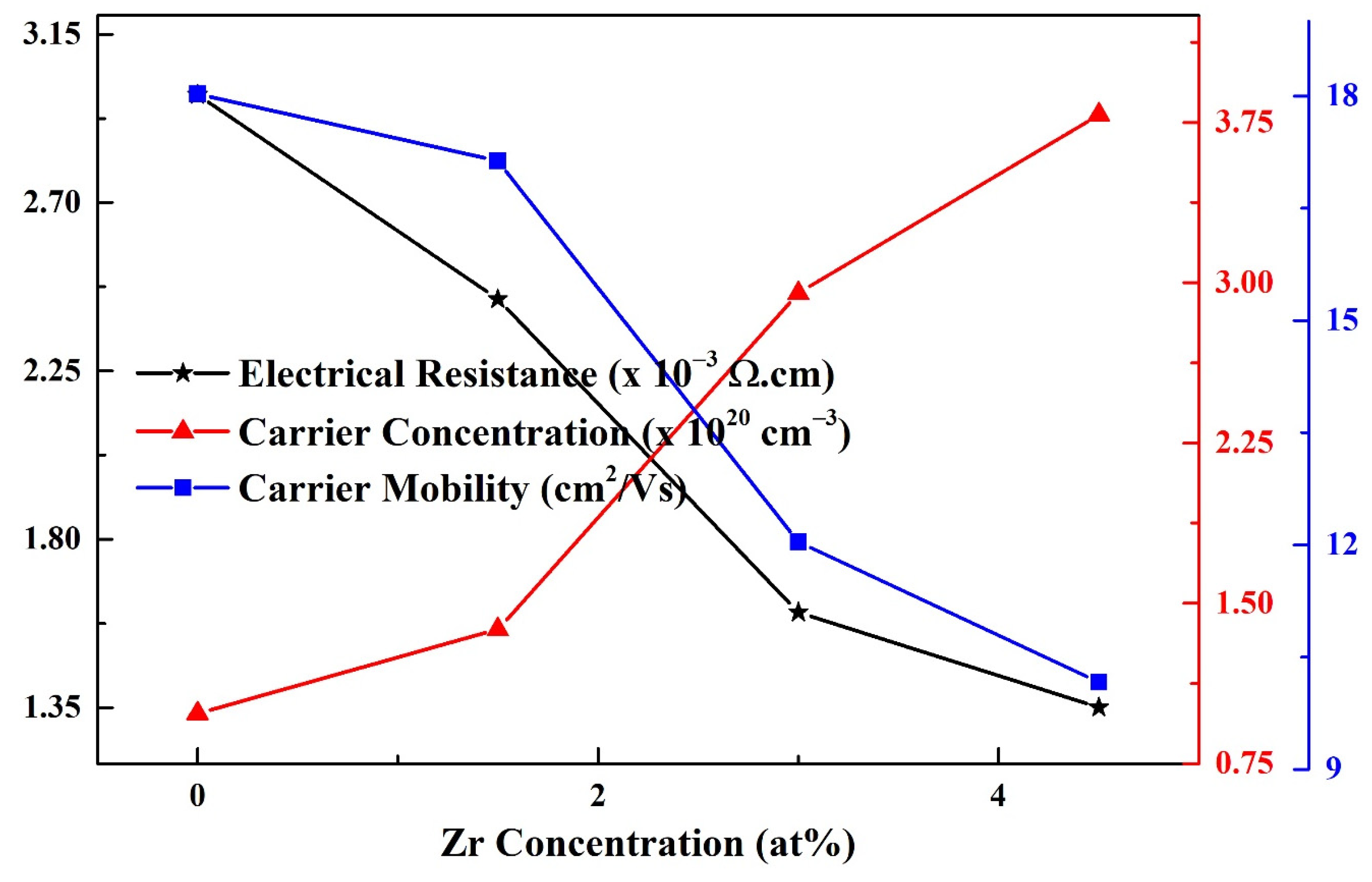
T” is the thickness of deposited nano layers, “ρ” is the sheet resistance in Ω/Sq. “I” is the applied current between the outer probes and “V” is the voltage difference between inner probes. The resistivity (Ω·cm) of the deposited thin films was obtained by multiplying the sheet resistance with thickness of thin layers. The resistivity of the deposited nanostructures was affected by doping of Zr. As the Zr concentration increased, the resistivity decreased, as shown in Figure 11.
The ZZO-D sample exhibited the minimum value of resistivity, 1.35 × 10⁻³ Ω·cm, which needed further reduction to match the resistance of the ITO. Available literature reported that doping causes a reduction in the resistivity of ZnO systems [28,68,71]. The reduction in electrical resistance with increasing concentration of Zr may be due to the increase in free electron density [47].
The carrier mobility “µh” (cm2/Vs) and carrier concentration “µe” (cm−3) can be measured by using the following equations with Hall Effect measurements, and the results are depicted in Figure 9 and Table 2 [72].
µ h = V h T I B R
µ e = 1 n e R
where “T” is the thickness of ZZO thin films, “Vh” is Hall voltage, “I” is electric current, “B” is a magnetic field, “R” is the resistivity, and “ne” is electron carrier concentration. The carrier concentration for 4.5% zirconium-doped ZZO-D thin films had a maximum carrier concentration value of 3.78 × 1020 cm−3 compared with other thin films with 10.2 cm2V−1s−1 carrier mobility. Carrier density in the order of 1020 cm−3 or higher is the requirement for transparent conductor oxides [20]. Electrical resistivity is consistent with the carrier concentration; for this reason, the increase in carrier concentration for ZZO-D is the same, and causes a reduction in electrical resistivity.

4. Conclusions

Zr-doped ZnO nanostructures were fabricated by sol–gel and spin-coating techniques to achieve better properties for optoelectronic applications. The XRD analysis confirmed the hexagonal wurtzite structure of synthesized single-phase nanostructures. The average crystallite size increased from 15 to 20 nm with increasing concentrations of doping element (Zr). FTIR analysis showed the stretching mode of ZnO from 465 to 453 cm−1. SEM images showed the agglomerated surface morphology of deposited nanostructures. Raman spectroscopy revealed the presence of oxygen vacancies in the deposited nanostructures. The electrical resistance of the deposited nanostructures reduced with increasing concentrations of Zr and ZZO-D; the nanostructures exhibited the minimum value of resistivity of ~1.35 × 10⁻³ Ω·cm. PL emission analysis showed a blue shift in EHP emission with increasing concentrations of Zr in ZnO. A low value of resistivity 1.35 × 10⁻³ Ω·cm, high carrier concentration 3.81 × 1020 cm−3, tuned optical band gap, and widening of transmittance of the deposited nanostructures are advantages for optoelectronic devices and could make them a better candidate in the future for replacing the ITO for TCO applications.

Author Contributions

Conceptualization, A.u.R.K.; data curation, M.I., M.Z., S.S., S.J.A., F.F. and M.F.I.; formal analysis, A.u.R.K., M.R., S.S. and M.F.I.; funding acquisition, S.S. and F.F.; investigation, A.u.R.K., M.R., M.I., M.Z., S.S., S.J.A., F.F. and M.F.I.; methodology, A.u.R.K., M.R., F.F. and M.F.I.; project administration, M.R.; resources, M.R., S.S., F.F. and M.F.I.; software, M.R., M.I. and S.S.; supervision, M.R.; validation, A.u.R.K., S.J.A. and F.F.; visualization, A.u.R.K., M.Z., S.S. and F.F.; writing—original draft, A.u.R.K.; writing—review and editing, M.R., M.I. and M.F.I. All authors have read and agreed to the published version of the manuscript.

Funding

This research received no external funding.

Institutional Review Board Statement

Not applicable.

Informed Consent Statement

Not applicable.

Data Availability Statement

The data related to this manuscript can be available on reasonable request from corresponding authors.

Acknowledgments

This research was supported by the Princess Nourah bint Abdulrahman University Researchers Supporting Project number (PNURSP2022R259), Princess Nourah bint Abdulrahman University, Riyadh, Saudi Arabia and authors are very thankful for their support. The authors are also thankful to the Al-Mustaqbal University College (Grant number: MUC-G-0322) for their support.

Conflicts of Interest

The authors have no conflict of interest regarding this manuscript.

References

  1. Zhong, Z.; Jiang, Y. Surface modification and characterization of indium–tin oxide for organic light-emitting devices. J. Colloid Interface Sci. 2006, 302, 613–619. [Google Scholar] [CrossRef] [PubMed]
  2. Bellingham, J.; Mackenzie, A.; Phillips, W. Precise measurements of oxygen content: Oxygen vacancies in transparent conducting indium oxide films. Appl. Phys. Lett. 1991, 58, 2506–2508. [Google Scholar] [CrossRef]
  3. Valentini, A.; Quaranta, F.; Penza, M.; Rizzi, F.R. The stability of zinc oxide electrodes fabricated by dual ion beam sputtering. J. Appl. Phys. 1993, 73, 1143–1145. [Google Scholar] [CrossRef]
  4. Park, C.Y.; Lee, J.H.; Choi, B.H. Effects of surface treatment of ITO anode layer patterned with shadow mask technology on characteristics of organic light-emitting diodes. Org. Electron. 2013, 14, 3172–3179. [Google Scholar] [CrossRef]
  5. Kang, H.; Lu, Z.; Zhong, Z.; Gu, J. Structural, optical and electrical characterization of Ga-Mg co-doped ZnO transparent conductive films. Mater. Lett. 2018, 215, 102–105. [Google Scholar] [CrossRef]
  6. Wu, J.-L.; Lin, H.-Y.; Su, B.-Y.; Chen, Y.-C.; Chu, S.-Y.; Liu, S.-Y.; Chang, C.-C.; Wu, C.-J. Comparison of physical and electrical properties of GZO/ZnO buffer layer and GZO as source and drain electrodes of α-IGZO thin-film transistors. J. Alloys Compd. 2014, 592, 35–41. [Google Scholar] [CrossRef]
  7. Ozasa, K.; Ye, T.; Aoyagi, Y. Deposition of thin indium oxide film and its application to selective epitaxy for in situ processing. Thin Solid Films 1994, 246, 58–64. [Google Scholar] [CrossRef]
  8. Sawada, M.; Higuchi, M.; Kondo, S.; Saka, H. Characteristics of indium-tin-oxide/silver/indium-tin-oxide sandwich films and their application to simple-matrix liquid-crystal displays. Jpn. J. Appl. Phys. 2001, 40, 3332–3336. [Google Scholar] [CrossRef]
  9. Marikkannu, S.; Kashif, M.; Sethupathy, N.; Vidhya, V.; Piraman, S.; Ayeshamariam, A.; Bououdina, M.; Ahmed, N.M.; Jayachandran, M. Effect of substrate temperature on indium tin oxide (ITO) thin films deposited by jet nebulizer spray pyrolysis and solar cell application. Mater. Sci. Semicond. Process. 2014, 27, 562–568. [Google Scholar] [CrossRef]
  10. Huang, J.; Chu, S.; Kong, J.; Liu, J. ZnO pn homojunction random laser based on nitrogen doped p-type nanowires. In Proceedings of the 2013 IEEE Photonics Conference, Bellevue, WA, USA, 8–12 September 2013. [Google Scholar]
  11. Lu, Y.-J.; Shi, Z.-F.; Shan, C.-X.; Shen, D.-Z. ZnO-based deep-ultraviolet light-emitting devices. Chin. Phys. B 2017, 26, 047703. [Google Scholar] [CrossRef]
  12. Kim, W.-S.; Moon, Y.-K.; Kim, K.-T.; Shin, S.-Y.; Du Ahn, B.; Lee, J.-H.; Park, J.-W. The influence of hafnium doping on bias stability in zinc oxide thin film transistors. Thin Solid Films 2011, 519, 5161–5164. [Google Scholar] [CrossRef]
  13. Martinson, A.B.; Elam, J.W.; Hupp, J.T.; Pellin, M.J. ZnO Nanotube Based Dye-Sensitized Solar Cells. Nano Lett. 2007, 7, 2183–2187. [Google Scholar] [CrossRef] [PubMed]
  14. Lupan, O.; Pauporté, T.; Le Bahers, T.; Viana, B.; Ciofini, I. Wavelength-Emission Tuning of ZnO Nanowire-Based Light-Emitting Diodes by Cu Doping: Experimental and Computational Insights. Adv. Funct. Mater. 2011, 21, 3564–3572. [Google Scholar] [CrossRef]
  15. Iwan, S.; Bambang, S.; Zhao, J.; Tan, S.; Fan, H.; Sun, L.; Zhang, S.; Ryu, H.; Sun, X. Green electroluminescence from an n-ZnO: Er/p-Si heterostructured light-emitting diode. Phys. B Condens. Matter 2012, 407, 2721–2724. [Google Scholar] [CrossRef]
  16. Jang, J.S.; Kim, J.; Ghorpade, U.; Shin, H.H.; Gang, M.G.; Park, S.D.; Kim, H.-J.; Lee, D.S.; Kim, J.H. Comparison study of ZnO-based quaternary TCO materials for photovoltaic application. J. Alloys Compd. 2019, 793, 499–504. [Google Scholar] [CrossRef]
  17. Ansari, M.Z.; Seo, K.-M.; Kim, S.-H.; Ansari, S.A. Critical Aspects of Various Techniques for Synthesizing Metal Oxides and Fabricating Their Composite-Based Supercapacitor Electrodes: A Review. Nanomaterials 2022, 12, 1873. [Google Scholar] [CrossRef]
  18. Mwankemwa, B.S.; Malevu, T.D.; Sahini, M.G.; Vuai, S.A. Effects of vertically aligned ZnO nanorods surface morphology on the ambient-atmosphere fabricated organic solar cells. Results Mater. 2022, 14, 100271. [Google Scholar] [CrossRef]
  19. Rezaie, M.N.; Mohammadnejad, S.; Ahadzadeh, S. The impact of ZnO nanotube on the performance of hybrid inorganic/organic light-emitting diode as a single-mode ring-core UV waveguide. Surf. Interfaces 2022, 28, 101666. [Google Scholar] [CrossRef]
  20. Minami, T. Transparent conducting oxide semiconductors for transparent electrodes. Semicond. Sci. Technol. 2005, 20, S35–S44. [Google Scholar] [CrossRef]
  21. Klingshirn, C. ZnO: From basics towards applications. Phys. Status Solidi (b) 2007, 244, 3027–3073. [Google Scholar] [CrossRef]
  22. Tsay, C.-Y.; Lee, W.-C. Effect of dopants on the structural, optical and electrical properties of sol–gel derived ZnO semiconductor thin films. Curr. Appl. Phys. 2013, 13, 60–65. [Google Scholar] [CrossRef]
  23. Fay, S.; Steinhauser, J.; Oliveira, N.; Vallat-Sauvain, E.; Ballif, C. Opto-electronic properties of rough LP-CVD ZnO: B for use as TCO in thin-film silicon solar cells. Thin Solid Films 2007, 515, 8558–8561. [Google Scholar] [CrossRef]
  24. Faÿ, S.; Steinhauser, J.; Nicolay, S.; Ballif, C. Polycrystalline ZnO: B grown by LPCVD as TCO for thin film silicon solar cells. Thin Solid Films 2010, 518, 2961–2966. [Google Scholar] [CrossRef]
  25. Huang, C.; Wang, M.; Deng, Z.; Cao, Y.; Liu, Q.; Huang, Z.; Liu, Y.; Guo, W.; Huang, Q. Low content indium-doped zinc oxide films with tunable work function fabricated through magnetron sputtering. Semicond. Sci. Technol. 2010, 25, 045008. [Google Scholar] [CrossRef]
  26. Hafdallah, A.; Ynineb, F.; Aida, M.; Attaf, N. In doped ZnO thin films. J. Alloys Compd. 2011, 509, 7267–7270. [Google Scholar] [CrossRef]
  27. Wang, C.; Man, B.; Liu, M.; Chen, C.; Jiang, S.; Yang, S.; Xu, S.; Gao, X.; Hu, B. The intrinsic room-temperature ferromagnetism in ZnO: Co thin films deposited by PLD. Adv. Condens. Matter Phys. 2012, 2012, 363981. [Google Scholar] [CrossRef] [Green Version]
  28. Chalker, P.R.; Marshall, P.A.; King, P.J.; Dawson, K.; Romani, S.; Williams, P.A.; Ridealgh, J.; Rosseinsky, M.J. Atomic layer deposition of germanium-doped zinc oxide films with tuneable ultraviolet emission. J. Mater. Chem. 2012, 22, 12824–12829. [Google Scholar] [CrossRef]
  29. Ahn, C.H.; Kim, J.H.; Cho, H.K. Tunable electrical and optical properties in composition controlled Hf: ZnO thin films grown by atomic layer deposition. J. Electrochem. Soc. 2012, 159, H384. [Google Scholar] [CrossRef]
  30. Gokulakrishnan, V.; Parthiban, S.; Jeganathan, K.; Ramamurthi, K. Investigation on the effect of Zr doping in ZnO thin films by spray pyrolysis. Appl. Surf. Sci. 2011, 257, 9068–9072. [Google Scholar] [CrossRef]
  31. Alam, M.W.; Ansari, M.Z.; Aamir, M.; Waheed-Ur-Rehman, M.; Parveen, N.; Ansari, S.A. Preparation and Characterization of Cu and Al Doped ZnO Thin Films for Solar Cell Applications. Crystals 2022, 12, 128. [Google Scholar] [CrossRef]
  32. Dhakal, T.; Vanhart, D.; Christian, R.; Nandur, A.; Sharma, A.; Westgate, C.R. Growth morphology and electrical/optical properties of Al-doped ZnO thin films grown by atomic layer deposition. J. Vac. Sci. Technol. A Vac. Surf. Films 2012, 30, 021202. [Google Scholar] [CrossRef]
  33. Chalker, P.R.; Marshall, P.; Romani, S.; Roberts, J.; Irvine, S.; Lamb, D.; Clayton, A.; Williams, P. Atomic layer deposition of Ga-doped ZnO transparent conducting oxide substrates for CdTe-based photovoltaics. J. Vac. Sci. Technol. A Vac. Surf. Films 2013, 31, 01A120. [Google Scholar] [CrossRef]
  34. Saito, K.; Hiratsuka, Y.; Omata, A.; Makino, H.; Kishimoto, S.; Yamamoto, T.; Horiuchi, N.; Hirayama, H. Atomic layer deposition and characterization of Ga-doped ZnO thin films. Superlattices Microstruct. 2007, 42, 172–175. [Google Scholar] [CrossRef]
  35. Saadi, H.; Benzarti, Z.; Rhouma, F.I.H.; Sanguino, P.; Guermazi, S.; Khirouni, K.; Vieira, M.T. Enhancing the electrical and dielectric properties of ZnO nanoparticles through Fe doping for electric storage applications. J. Mater. Sci. Mater. Electron. 2021, 32, 1536–1556. [Google Scholar] [CrossRef]
  36. Saadi, H.; Benzarti, Z.; Sanguino, P.; Hadouch, Y.; Mezzane, D.; Khirouni, K.; Abdelmoula, N.; Khemakhem, H. Improving the optical, electrical and dielectric characteristics of ZnO nanoparticles through (Fe+ Al) addition for optoelectronic applications. Appl. Phys. A 2022, 128, 1–15. [Google Scholar] [CrossRef]
  37. Demirkol, U.; Pat, S.; Mohammadigharehbagh, R.; Musaoğlu, C.; Özgür, M.; Elmas, S.; Özen, S.; Korkmaz, Ş. Investigation of the substrate effect for Zr doped ZnO thin film deposition by thermionic vacuum arc technique. J. Mater. Sci. Mater. Electron. 2018, 29, 18098–18104. [Google Scholar] [CrossRef]
  38. Yang, L.-L.; Yang, J.-H.; Wang, D.-D.; Zhang, Y.-J.; Wang, Y.-X.; Liu, H.-L.; Fan, H.-G.; Lang, J.-H. Photoluminescence and Raman analysis of ZnO nanowires deposited on Si (1 0 0) via vapor–liquid–solid process. Phys. E Low-Dimens. Syst. Nanostruct. 2008, 40, 920–923. [Google Scholar] [CrossRef]
  39. Sathya, M.; Pushpanathan, K. Synthesis and Optical Properties of Pb Doped ZnO Nanoparticles. Appl. Surf. Sci. 2018, 449, 346–357. [Google Scholar] [CrossRef]
  40. Bian, H.; Ma, S.; Yang, G.; Zhu, H.; Xu, X.; Yan, S.; Gao, J.; Zhang, Z. The optical and electrical properties of ZnO: Zr films. J. Alloys Compd. 2016, 672, 20–26. [Google Scholar] [CrossRef]
  41. Machda, F.; Ogawa, T.; Okumura, H.; Ishihara, K.N. Damp-heat durability comparison of Al-doped ZnO transparent electrodes deposited at low temperatures on glass and PI-tape/PC substrates. Ceram. Int. 2020, 46, 16178–16184. [Google Scholar] [CrossRef]
  42. Liu, Y.-Y.; Yuan, Y.-Z.; Li, C.-F.; Gao, X.-T.; Cao, X.-Z.; Li, J.-B. The structure and photoluminescence properties of RF-sputtered films of ZnO on Teflon substrate. Mater. Lett. 2008, 62, 2907–2909. [Google Scholar] [CrossRef]
  43. Selvam, N.C.S.; Vijaya, J.J.; Kennedy, L.J. Effects of Morphology and Zr Doping on Structural, Optical, and Photocatalytic Properties of ZnO Nanostructures. Ind. Eng. Chem. Res. 2012, 51, 16333–16345. [Google Scholar] [CrossRef]
  44. Smaali, A.; Abdelli-Messaci, S.; Lafane, S.; Mavlonov, A.; Lenzner, J.; Richter, S.; Kechouane, M.; Nemraoui, O.; Ellmer, K. Pulsed laser deposited transparent and conductive V-doped ZnO thin films. Thin Solid Films 2020, 700, 137892. [Google Scholar] [CrossRef]
  45. Tsay, C.-Y.; Fan, K.-S. Optimization of Zr-doped ZnO thin films prepared by sol-gel method. Mater. Trans. 2008, 49, 1900–1904. [Google Scholar] [CrossRef] [Green Version]
  46. Pelicano, C.M.; Raifuku, I.; Ishikawa, Y.; Uraoka, Y.; Yanagi, H. Hierarchical core–shell heterostructure of H2O-oxidized ZnO nanorod@ Mg-doped ZnO nanoparticle for solar cell applications. Mater. Adv. 2020, 1, 1253–1261. [Google Scholar] [CrossRef]
  47. Hussain, S.; Jacob, J.; Usman, Z.; Mahmood, K.; Ali, A.; Arshad, M.; Khan, W.S.; Farooq, Z.; Farooq, M.; Ashfaaq, A.; et al. Length dependent performance of Cu2O/ZnO nanorods solar cells. Superlattices Microstruct. 2019, 126, 181–185. [Google Scholar] [CrossRef]
  48. Özgür, Ü.; Hofstetter, D.; Morkoç, H. ZnO devices and applications: A review of current status and future prospects. Proc. IEEE 2010, 98, 1255–1268. [Google Scholar] [CrossRef]
  49. Nithin, K.K.; Krishnappa, M.R. Synthesis and characterization of cobalt-doped cadmium oxide thin films prepared by sol–gel spin coating method. J. Physics: Conf. Ser. 2019, 1362, 012118. [Google Scholar]
  50. Paul, G.; Bandyopadhyay, S.; Sen, S.; Sen, S. Structural, optical and electrical studies on sol–gel deposited Zr doped ZnO films. Mater. Chem. Phys. 2003, 79, 71–75. [Google Scholar] [CrossRef]
  51. Naik, E.I.; Naik, H.B.; Viswanath, R.; Kirthan, B.; Prabhakara, M. Effect of zirconium doping on the structural, optical, electrochemical and antibacterial properties of ZnO nanoparticles prepared by sol-gel method. Chem. Data Collect. 2020, 29, 100505. [Google Scholar] [CrossRef]
  52. Naik, E.I.; Naik, H.; Viswanath, R.; Gowda, I.; Prabhakara, M. Bright red luminescence emission of macroporous honeycomb-like Eu3+ ion-doped ZnO nanoparticles developed by gel-combustion technique. SN Appl. Sci. 2020, 2, 1–13. [Google Scholar] [CrossRef]
  53. Supatutkul, C.; Pramchu, S.; Jaroenjittichai, A.; Laosiritaworn, Y. Electronic properties of two-dimensional zinc oxide in hexagonal, (4,4)-tetragonal, and (4,8)-tetragonal structures by using Hybrid Functional calculation. J. Physics: Conf. Ser. 2017, 901, 012172. [Google Scholar] [CrossRef]
  54. Iqbal, M.F.; Saeed, S.; Wu, L.; Zhu, P.; Wang, D. Enhanced anharmonic phonon coupling and decay dominated by low-energy phonons in CdS nanowires. J. Raman Spectrosc. 2019, 50, 1492–1501. [Google Scholar] [CrossRef]
  55. Pradhan, A.; Zhang, K.; Loutts, G.; Roy, U.; Cui, Y.; Burger, A. Structural and spectroscopic characteristics of ZnO and ZnO: Er3+nanostructures. J. Physics: Condens. Matter 2004, 16, 7123–7129. [Google Scholar] [CrossRef]
  56. Khan, I.; Khan, S.; Nongjai, R.; Ahmed, H.; Khan, W. Structural and optical properties of gel-combustion synthesized Zr doped ZnO nanoparticles. Opt. Mater. 2013, 35, 1189–1193. [Google Scholar] [CrossRef]
  57. Artus, L.; Cusco, R.; Alarcon-Llado, E.; Gonzalez-Diaz, G.; Martil, I.; Jimenez, J.; Wang, B.; Callahan, M. Isotopic study of the nitrogen-related modes in N+- implanted ZnO. Appl. Phys. Lett. 2007, 90, 181911. [Google Scholar] [CrossRef] [Green Version]
  58. Pelicano, C.M.; Yanagi, H. pH-controlled surface engineering of nanostructured ZnO films generated via a sustainable low-temperature H2O oxidation process. Appl. Surf. Sci. 2019, 467, 932–939. [Google Scholar] [CrossRef]
  59. Urbach, F. The Long-Wavelength Edge of Photographic Sensitivity and of the Electronic Absorption of Solids. Phys. Rev. 1953, 92, 1324. [Google Scholar] [CrossRef]
  60. Rao, J.; Yu, A.; Shao, C.; Zhou, X. Construction of Hollow and Mesoporous ZnO Microsphere: A Facile Synthesis and Sensing Property. ACS Appl. Mater. Interfaces 2012, 4, 5346–5352. [Google Scholar] [CrossRef]
  61. Murtaza, G.; Ahmad, R.; Rashid, M.; Hassan, M.; Hussnain, A.; Khan, M.A.; ul Haq, M.E.; Shafique, M.; Riaz, S. Structural and magnetic studies on Zr doped ZnO diluted magnetic semiconductor. Curr. Appl. Phys. 2014, 14, 176–181. [Google Scholar] [CrossRef]
  62. Norouzzadeh, P.; Mabhouti, K.; Golzan, M.; Naderali, R. Comparative study on dielectric and structural properties of undoped, Mn-doped, and Ni-doped ZnO nanoparticles by impedance spectroscopy analysis. J. Mater. Sci. Mater. Electron. 2019, 31, 7335–7347. [Google Scholar] [CrossRef]
  63. Sohail, A.; Faraz, M.; Arif, H.; Bhat, S.A.; Siddiqui, A.A.; Bano, B. Deciphering the interaction of bovine heart cystatin with ZnO nanoparticles: Spectroscopic and thermodynamic approach. Int. J. Biol. Macromol. 2017, 95, 1056–1063. [Google Scholar] [CrossRef]
  64. Bindemann, R.; Kluge, G.; Elliott, R.J.; Ipatova, I.P. (Eds.) Optical Properties of Mixed Crystals; Modern Problems in Condensed Matter Sciences; North-Holland Publ. Co.: Amsterdam, The Netherlands, 1988; Volume 23, ISBN 044870695. [Google Scholar]
  65. Devi, P.G.; Velu, A.S. Synthesis, structural and optical properties of pure ZnO and Co doped ZnO nanoparticles prepared by the co-precipitation method. J. Theor. Appl. Phys. 2016, 10, 233–240. [Google Scholar] [CrossRef] [Green Version]
  66. Philips’Gloeilampenfabrieken, O. A method of measuring specific resistivity and Hall effect of discs of arbitrary shape. Philips Res. Rep. 1958, 13, 1–9. [Google Scholar]
  67. Kumrueng, W.; Sawanthai, K.; Tubtimtae, A.; Ponhan, W. Effect of pH treatment on the structural and optical properties of Sn6Sb10S21 thin films facilely synthesized using a spin coating method. Opt. Mater. 2020, 105, 109917. [Google Scholar] [CrossRef]
  68. Joshi, G.; Saxena, N.; Mangal, R.; Mishra, A.; Sharma, T. Band gap determination of Ni-Zn ferrites. Bull. Mater. Sci. 2003, 26, 387–389. [Google Scholar] [CrossRef]
  69. Ramzan, M.; Imran, M.; Ullah, S.; Khan, M.A.; Naz, G.; Ghouri, M.; Iqbal, H.M. Fabrication and characterization of multifunctional thin multi-layer films for transparent conducting oxides. Prog. Org. Coat. 2020, 149, 105976. [Google Scholar] [CrossRef]
  70. Lee, D.J.; Kim, H.M.; Kwon, J.Y.; Choi, H.; Kim, S.H.; Kim, K.B. Structural and electrical properties of atomic layer deposited Al-doped ZnO films. Adv. Funct. Mater. 2011, 21, 448–455. [Google Scholar] [CrossRef]
  71. Kim, K.-T.; Kim, G.-H.; Woo, J.-C.; Kim, C.-I. Characteristics of Nickel-doped Zinc Oxide thin films prepared by sol–gel method. Surf. Coat. Technol. 2008, 202, 5650–5653. [Google Scholar] [CrossRef]
  72. Iqbal, M.F.; Ain, Q.U.; Yaqoob, M.M.; Zhu, P.; Wang, D. Temperature dependence of exciton–phonon coupling and phonon anharmonicity in ZnTe thin films. J. Raman Spectrosc. 2022, 53, 1265–1274. [Google Scholar] [CrossRef]
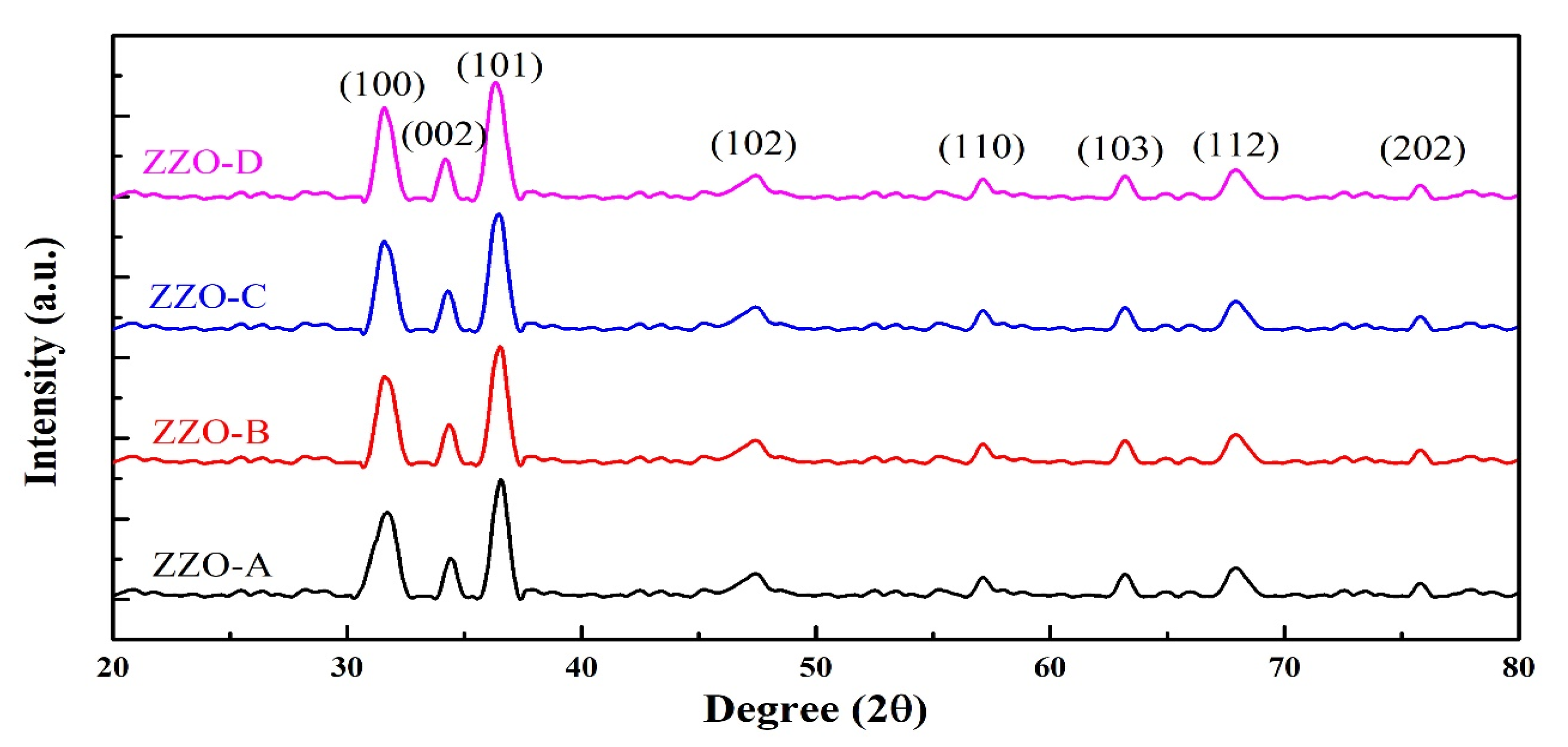
Figure 1. XRD patterns of ZrxZn1−xO, ZZO-(A-D) nanostructures.
Coatings 13 00034 g001
Figure 2. (a) Shifting of (100), (002), and (101) peaks, (b) lattice parameters “a” and “b”, (c) crystallite size “D” and micro strain “ε”, (d) Zn-O bond length and unit cell volume of deposited nanostructures with increasing content of Zr.
Coatings 13 00034 g002
Figure 3. W-H analysis of (a) ZZO-A, (b) ZZO-B, (c) ZZO-C, and (d) ZZO-D nanostructures.
Coatings 13 00034 g003
Figure 4. Raman spectra of ZrxZn1−xO, ZZO-(A-D) nanostructures.
Coatings 13 00034 g004
Figure 5. FTIR spectra of ZrxZn1−xO, ZZO-(A-D) nanostructures.
Coatings 13 00034 g005
Figure 6. SEM micrographs of (a) ZZO-A, (b), ZZO-B, (c), ZZO-C, and (d) ZZO-D nanostructures.
Coatings 13 00034 g006
Figure 7. EDX analysis of (a) ZZO-A, (b), ZZO-C, and (c) ZZO-D nanostructures.
Coatings 13 00034 g007
Figure 8. Optical transmittance of ZrxZn1−xO, ZZO-(A-D) nanostructures against wavelength range 300 to 2500 nm.
Coatings 13 00034 g008
Figure 9. (a) Optical absorbance and (b) optical band gap of ZZO-A, ZZO-B, ZZO-C and ZZO-D nanostructures.
Coatings 13 00034 g009
Figure 10. PL emission spectra of ZrxZn1-xO, ZZO-(A-D) nanostructures.
Coatings 13 00034 g010
Figure 11. Electrical resistance, carrier mobility, and carrier concentration of ZZO-(A–D) deposited nanostructures.
Coatings 13 00034 g011
Table 1. Structural parameters and optical bandgaps of ZZO-(A-D) nanostructures.
Samples IDZZO-AZZO-BZZO-CZZO-D
Crystallite size (nm) (Scherrer formula)15.1 ± 0.117.2 ± 0.118.8 ± 0.120.3 ± 0.1
Lattice constant a (Å)3.24473.24633.25213.2568
Lattice constant c (Å)5.21885.22745.23645.2526
c/a ratio1.60841.61021.61021.6128
Micro strain ε (×10−3) (Scherrer formula)2.522.222.051.97
Volume of unit cell V (Å3)14.664314.695714.747414.8144
Bond Length L (Å)1.88651.88761.89081.894
Crystallite size (nm) (W-H Plot)16.4 ± 0.117.6 ± 0.121.7 ± 0.121.9 ± 0.1
Micro strain ε (×10−3) (W-H Plot)6.674.434.174.12
Band gap (eV) 3.323.363.393.51
Table 2. Electrical measurements of ZZO-(A-D) nanostructures.
Samples IDZZO-AZZO-BZZO-CZZO-D
Resistivity (×10−3 Ω·cm)2.982.441.601.35
Carrier concentration (×1020 cm−3)0.981.372.953.78
Carrier mobility (cm2/Vs)18.017.112.010.2
Disclaimer/Publisher’s Note: The statements, opinions and data contained in all publications are solely those of the individual author(s) and contributor(s) and not of MDPI and/or the editor(s). MDPI and/or the editor(s) disclaim responsibility for any injury to people or property resulting from any ideas, methods, instructions or products referred to in the content.