Abstract
The oxidation behavior of two ternary Mo-Si-Ti alloys (eutectic Mo-20.0Si-52.8Ti and eutectoid Mo-21.0Si-34.0Ti) was investigated using thermogravimetric analysis at 700 °C, 900 °C, and 1300 °C for 100 h. The eutectic alloy formed a protective SiO2/TiO2 oxide scale, whereas the eutectoid alloy showed catastrophic oxidation. To improve the oxidation behavior of these alloys, chromium diffusion coatings deposited via pack cementation on the surface were investigated. Cr coatings were found to be suitable for improving oxidation resistance at 700 °C and 900 °C but failed at 1300 °C due to the evaporation of thin scales. At 700 °C and 900 °C, the formation of a Cr2O3 scale was proven on the Ti-rich/Mo-lean eutectic composition. After exposure, the Ti-lean/Mo-rich eutectoid composition, which is intrinsically more prone to oxidation, was found to form a continuous Cr2O3 scale only at 700 °C.
1. Introduction
The efficiency of high-temperature combustion processes in gas or aircraft turbines depends on the temperature [1]. In ongoing efforts to improve efficiency, refractory metal-silicide alloys have been investigated for several decades as potential substitutes for currently used Ni-based superalloys, allowing for higher operating temperatures. Due to their promising creep performance, three-phase Mo-Si-B alloys (mainly in the phase triangle of a Mo-rich bcc solid solution, tetragonal Mo5SiB2, and A15-type Mo3Si) have been intensively researched [2,3]. It has been shown that these alloys are highly susceptible to pesting, which is a catastrophic oxidation attack at temperatures below 1000 °C [4] resulting in the total breakdown of the material into powder as a consequence of MoO3 evaporation and grain boundary decay. The cause of this rapid disintegration is not fully understood, but it is clear that it is related to oxygen transport along the grain boundaries and resulting stresses within the material [5]. The intermediate temperature range holds significant importance, as it is passed through in every cycle of a high-temperature process and because of the substantial temperature variations within individual components. For example, the roots of turbine blades are approximately 500 °C cooler than their leading edge [6,7]. Other drawbacks of Mo-Si-B alloys are their brittleness at room temperature and higher density (9.5 g cm−3) [8] compared to Ni-based superalloys, ranging from 8.2 g cm−3 to 9 g cm−3 [9].
Alloying Ti to the Mo-Si-B alloys stabilizes MoSi instead of MoSi and favorably decreases the density to a range of 6.5 g cm−3 to 7.6 g cm−3 [10,11], paving the way for the next generation of Mo-based silicide alloys. However, Mo-Si-B-Ti alloys exhibit decreased oxidation resistance within a temperature range of 820–1200 °C. This has been linked to the formation of a porous SiO/TiO oxide scale and the coarsening of the microstructure resulting from heat treatment [11]. Aiming for an eutectic reaction or eutectoid decomposition to achieve a fine microstructure is a promising approach [12]. Studies have shown that the coarsening of the microstructure usually leads to a decrease in oxidation resistance [13]. This strategy is well-established in the ternary eutectic Mo-Si-B system [14,15] and has been combined with the approach of alloying with Ti, leading to the development of B-free two-phased eutectic and eutectoid Mo-Si-Ti alloys with a relatively low density of 6–7 g cm−3 [16]. The cyclic oxidation behavior of these alloys has been studied at 800 °C, 1100 °C, and 1200 °C, revealing a pesting resistance of the eutectic alloy (Mo-20.0Si-52.8Ti) at 800 °C, while the eutectoid alloy (Mo-21.0Si-34.0Ti) underwent catastrophic oxidation due to the higher Mo content [16]. Therefore, there is an interest in further improving the oxidation behavior and mitigating pesting.
The oxidation behavior of Mo-Si-Ti alloys is strongly dependent on the ratio between the Si and Ti contents [17]. Since TiO2 is generally considered non-protective in the temperature range of interest [18,19], the oxidation behavior could be further improved. This is possible through the application of Cr diffusion coatings via the industrially well-established method of pack cementation [20]. For Mo silicides, the majority of previous investigations focused on Si [21,22], Si-B [23,24,25,26], and Al coatings [27,28,29]. Nonetheless, Cr coatings offer a promising alternative, as Cr is miscible with Mo at high temperatures [30] and a Cr2O3 layer offers advantages in the intermediate temperature range, where hot corrosion is also an issue [31,32]. Until now, Cr coatings have been applied mainly on steel [33,34,35,36,37,38,39] and Ni-based alloys [40,41,42] using chlorine activators. In this work, they are applied on eutectic and eutectoid Mo-Si-Ti alloys to investigate the isothermal oxidation behavior in a wide temperature range of 700 °C to 1300 °C. The oxidation tests at 700 °C and 900 °C cover the critical pesting regime, and the isothermal exposure tests at 1300 °C extend the existing cyclic oxidation results by 200 °C.
2. Materials and Methods
2.1. Alloy Manufacturing
Two ternary alloys within the Mo-Si-Ti system (eutectic Mo-20.0Si-52.8Ti (at%) and eutectoid Mo-21.0Si-34.0Ti (at%)) were chosen as substrate materials. Alloys were melted from the elemental materials Mo (99.95%, EVOCHEM, Offenbach am Main, Germany), Si (99.99%, ChemPUR, Karlsruhe, Germany), and Ti (≥99.8%, ChemPUR) using an arc melter (AM/0.5, Edmund Bühler GmbH, Bodelshausen, Germany).
The arc melting process was carried out in a water-cooled Cu crucible, with an Ar (>99.998%) base pressure of 600 mbar, after the vacuum chamber had been evacuated to 10−4 mbar. To achieve a homogeneous alloy composition, each ingot was remelted five times and flipped after each cycle. Before each melting step, a Zr getter was remelted to minimize the residual oxygen within the vacuum chamber. In a final arc melting step, the ingots of the two Mo-Si-Ti alloys were drop-casted into a mold, forming rods with a diameter of 12–14 mm and a length of 150 mm. Subsequently, the Mo-21.0Si-34.0Ti alloy was heat-treated at 1300 °C in a resistance tube furnace (HTRH 70-600/18, Carbolite Gero GmbH & Co. KG, Neuhausen, Germany) under an Ar (>99.998%) atmosphere for a duration of 200 h. All alloys were cut to the required geometries (height 3, diameter 12–14 mm) using arc wire cutting and ground with P 500 silicon carbide paper to remove any Cu contamination that could have been introduced by wire erosion. Finally, the surface was cleaned in acetone in an ultrasonic bath to remove any remaining organic impurities.
2.2. Coating Manufacturing
The pack cementation (in-pack) powder was composed of Cr (≥99%, Alfa Aesar, Haverhill, MA, USA) as the diffusant, either CrCl (97%, Alfa Aesar) or NH4Br (≥99.0%, Alfa Aesar) as the halide activator, and an inert filler (Al2O3, ≥98%, Honeywell, Charlotte, NC, USA). Different powder compositions, ranging from 15 to 50 Cr and from to activator, were assessed. Table 1 displays the powder compositions and temperatures that yielded homogeneous and dense layers on the two Mo-Si-Ti alloys. To avoid chlorine corrosion, NHBr was used as the activator during Cr pack cementation of the eutectic Mo-20.0Si-52.8Ti alloy. Analogous to their electronegativity, the reactivity of halogens decreases with increasing periods [43]. Furthermore, due to the greater atomic radius of Br, diffusion occurs at a slower rate compared to Cl. Nevertheless, the decomposition temperature of NHBr at about 400 is low enough to provide a sufficient amount of bromide species during pack cementation.

Table 1.
Pack cementation conditions for the different substrate materials.
During each pack cementation cycle, four samples were coated simultaneously in a covered alumina crucible, with an average ratio of powder to surface area of 6–8 g cm−2. The pack cementation process was conducted in a (100 mm diameter) quartz tube furnace (HZS 12/600, Carbolite Gero GmbH & Co. KG) at 1100 °C, following a 6 h drying step under an Ar (99.999%, Air Liquide, Paris, France) atmosphere at 150 °C. Once the coating temperature was reached at a rate of 7 °C min−1, it was held under an Ar atmosphere (flow rate of 102 cm h−1) for 8 h. To investigate the influence of H, 5 H was added to the Ar atmosphere during selected pre-experiments. Any remaining pack cementation powder on the specimens was removed in acetone within an ultrasonic bath for 10 . Finally, the samples were weighed to check the mass increase due to the pack cementation, with a standard deviation in mass change of 2 .
2.3. Thermogravimetric Oxidation
The oxidation behavior and kinetics of the uncoated and coated alloys were recorded continuously (1 data point min−1) in situ up to 100 h using thermogravimetric analysis (TGA). The samples were subjected to oxidation tests at 700 (M25D-V (Sartorius, Göttingen, Germany), RAS 50/250/12 (Thermconcept, Bremen, Germany)), 900 (TGA 92 (Setaram, Caluire-et-Cuire, Frankreich), TZF 12/65/550 (Carbolite Gero GmbH & Co. KG)), and 1300 (M25D-V (Sartorius), HT 04/17 (Nabertherm GmbH, Lilienthal, Germany)) in dry synthetic air (80% N and 20% O), with a flow velocity of 205 cm h−1. A small holder, crafted from quartz glass (for 700 and 900 ) or alumina tubes connected with Pt wire (for 1300 ), was used to attach the samples to the precision balance. During measurements at 700 or 900 , the furnace was heated at a rate of 10 /. To avoid temperature overshooting, the temperature was gradually increased during the measurements at 1300 : to 1200 at a rate of 15 /, then to 1290 at a rate of 10 /, and finally to 1300 at a rate of 5 /. After completion of the oxidation experiment, the furnace was switched off, and the sample was left inside until it had cooled down. To ensure data reproducibility, some experiments were repeated.
2.4. Microstructural Analysis
Macroscopic images of the samples before and after pack cementation, as well as after the oxidation experiments, were taken using a Leica MZ16 A stereomicroscope. A D8 Advance A25 (Bruker, Billerica, MA, USA) equipped with a Cu-K tube was utilized to conduct X-ray diffraction (XRD) measurements on the surfaces. A step size of 0.015° with a dwell time of 0.5 s per step in the measurement range from 20° to 110° and Bragg–Brentano configuration was used. Afterward, samples were cut in half and coated with gold via plasma sputtering, electroplated with nickel, and mounted in an epoxy resin. The cross-sections were ground with a series of silicon carbide papers to P 2400 and then polished using 3 μm and 1 μm diamond suspensions, as well as a colloidal silicon oxide suspension. Light microscopy and scanning electron microscopy (SEM, FlexSEM 1000II (Hitachi, Tokyo, Japan) with an energy dispersive X-ray spectrometer (EDX)) were utilized to examine the cross-sections and determine the average and standard deviation of the layer thicknesses based on at least four separate measurements. The JEOL JXA-8100 electron probe microanalyzer (EPMA) was used to record quantitative concentration profile measurements and semiquantitative element maps.
3. Results and Discussion
3.1. Chromium Diffusion Coating Investigations
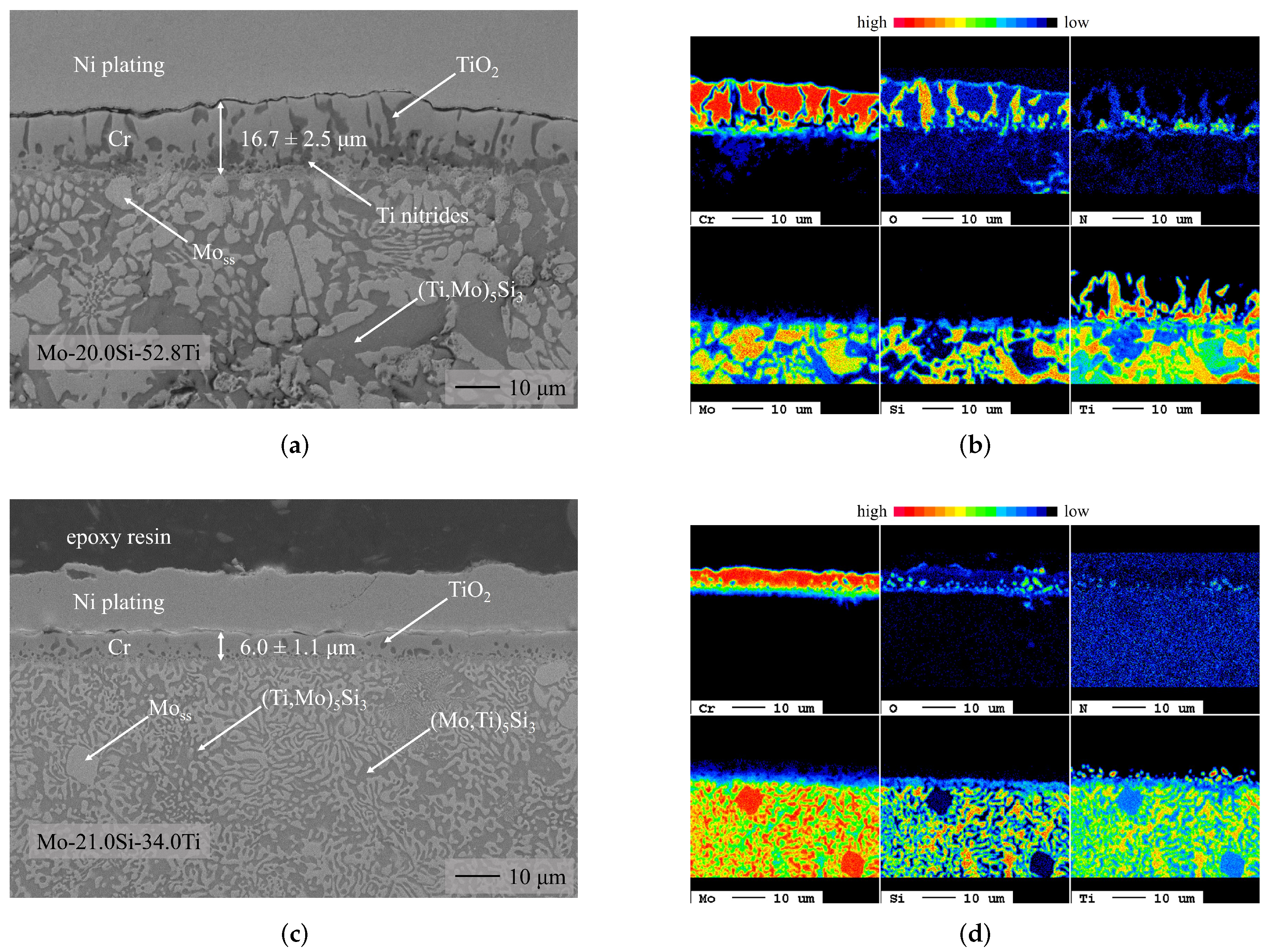
Figure 1 shows the backscattered electron (BSE) images of the coatings on the Mo-Si-Ti substrates after pack cementation, along with the corresponding semiquantitative EPMA element maps.

Figure 1.
BSE images (left) and EPMA maps (right) of the different phases formed on the ternary Mo-Si-Ti alloys after Cr pack cementation under a pure Ar atmosphere. The BSE images and the corresponding EPMA maps vary in magnification. (a) Cr-coated eutectic Mo-20.0Si-52.8Ti. (b) Cr-coated eutectic Mo-20.0Si-52.8Ti. (c) Cr-coated eutectoid Mo-21.0Si-34.0Ti. (d) Cr-coated eutectoid Mo-21.0Si-34.0Ti.
The EPMA data combined with the EDX and XRD measurements (see Appendix A) were used to identify an outer body-centered cubic (bcc, Imm, 229) Cr layer with larger TiO and nitride inclusions on the Ti-rich eutectic alloy compared to the eutectoid alloy. According to the Cr-Ti phase diagram, Cr exhibits a moderate solubility for Ti [44,45]; therefore, it is likely that Ti is dissolved from the substrate into the diffusion layer during the pack cementation process. The residual oxygen in the pack cementation atmosphere (1 × 10⁻²⁴ atm to 1 × 10⁻²⁰ atm) is sufficient to oxidize Ti due to the high affinity of Ti to oxygen [46,47]. This oxidation is more pronounced for the Ti-rich eutectic alloy (see Figure 1a), on which the coating is also substantially thicker than on the eutectoid alloy (see Figure 1c). The increased layer thickness is a result of the higher Cr content in the pack cementation powder and the accelerated diffusion into the substrate material compared to the Mo-rich eutectoid alloy [48,49]. According to Le Chatelier’s principle [50], a change in concentration by adding more reactants to the reaction (in the form of Cr powder) causes the equilibrium of the deposition reaction to shift to the product side, leading to the deposition of thicker bcc Cr layers.
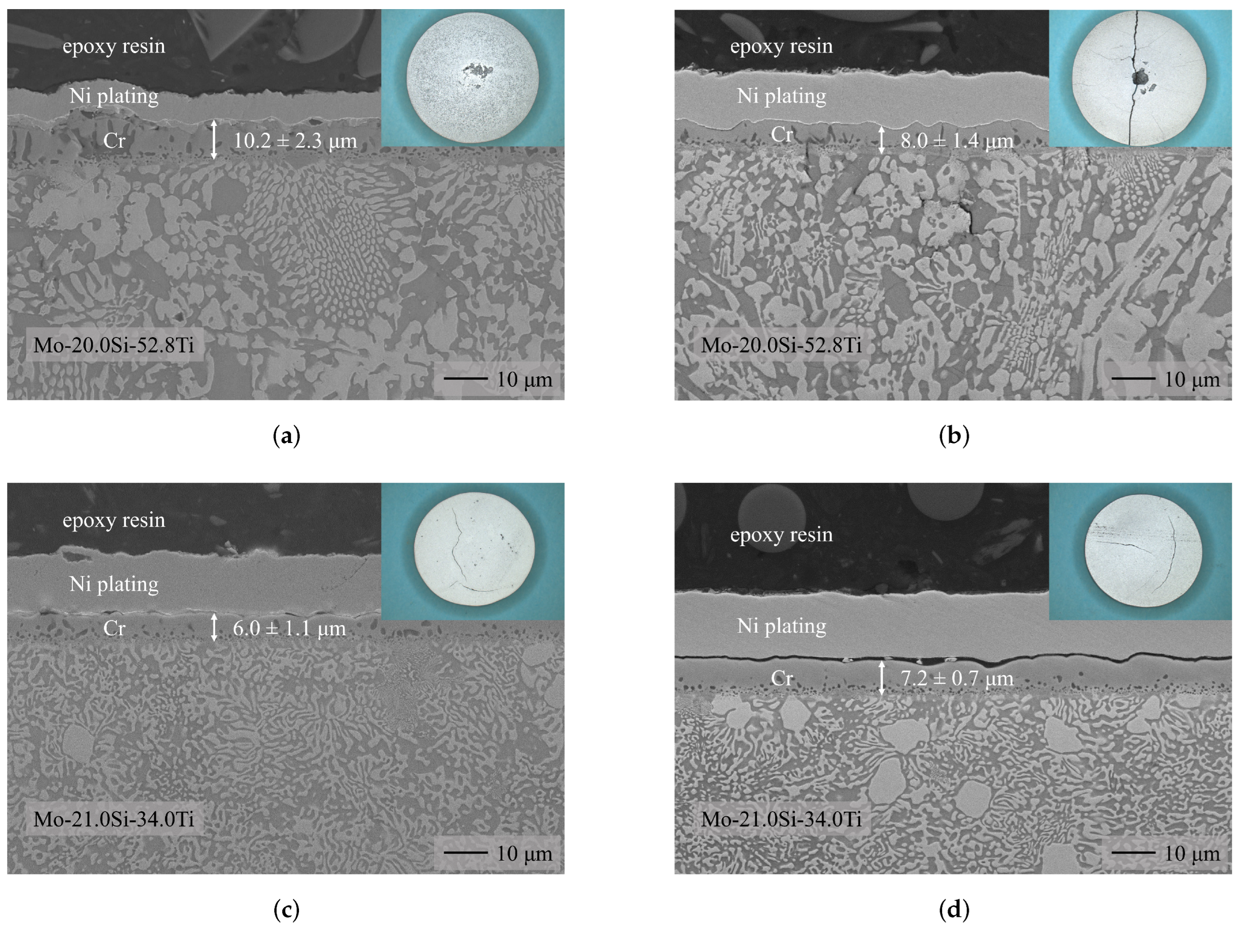
The oxidation of the substrate material by residual oxygen is usually counteracted by adding 5% H to the pack cementation atmosphere [51]. Indeed, fewer and smaller TiO inclusions were found after the pack cementation process in an H-containing atmosphere during pre-experiments (see Figure 2). The layer structures obtained are similar to the coatings under a pure Ar atmosphere; bcc Cr layers with comparable thicknesses were formed. However, when H was present in the pack cementation atmosphere, notable cracking was observed in the underlying Ti-rich eutectic alloy of the Mo-Si-Ti substrate, but not in the Ti-lean eutectoid alloy. This can be attributed to the higher Ti content, along with the susceptibility of Ti to hydrogen embrittlement, as reported in several studies [52,53,54]. Therefore the addition of H to the pack cementation atmosphere was avoided when coating Mo-Si-Ti substrates.
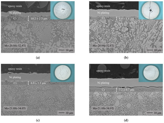
Figure 2.
BSE images of the result of the Cr pack cementation (15 wt% Cr, 2.5 wt% CrCl2, 82.5 wt% Al2O3, 1100 °C, 8 h) of the Mo-Si-Ti alloys in different atmospheres. In the H2-containing atmosphere cracking of the substrate occurs. (a) Cr-coated Mo-20.0Si-52.8Ti (Ar). (b) Cr-coated Mo-20.0Si-52.8Ti (Ar/H2). (c) Cr-coated Mo-21.0Si-34.0Ti (Ar). (d) Cr-coated Mo-21.0Si-34.0Ti (Ar/H2).
3.2. Oxidation Behavior Investigations
3.2.1. Uncoated Mo-Si-Ti Alloys
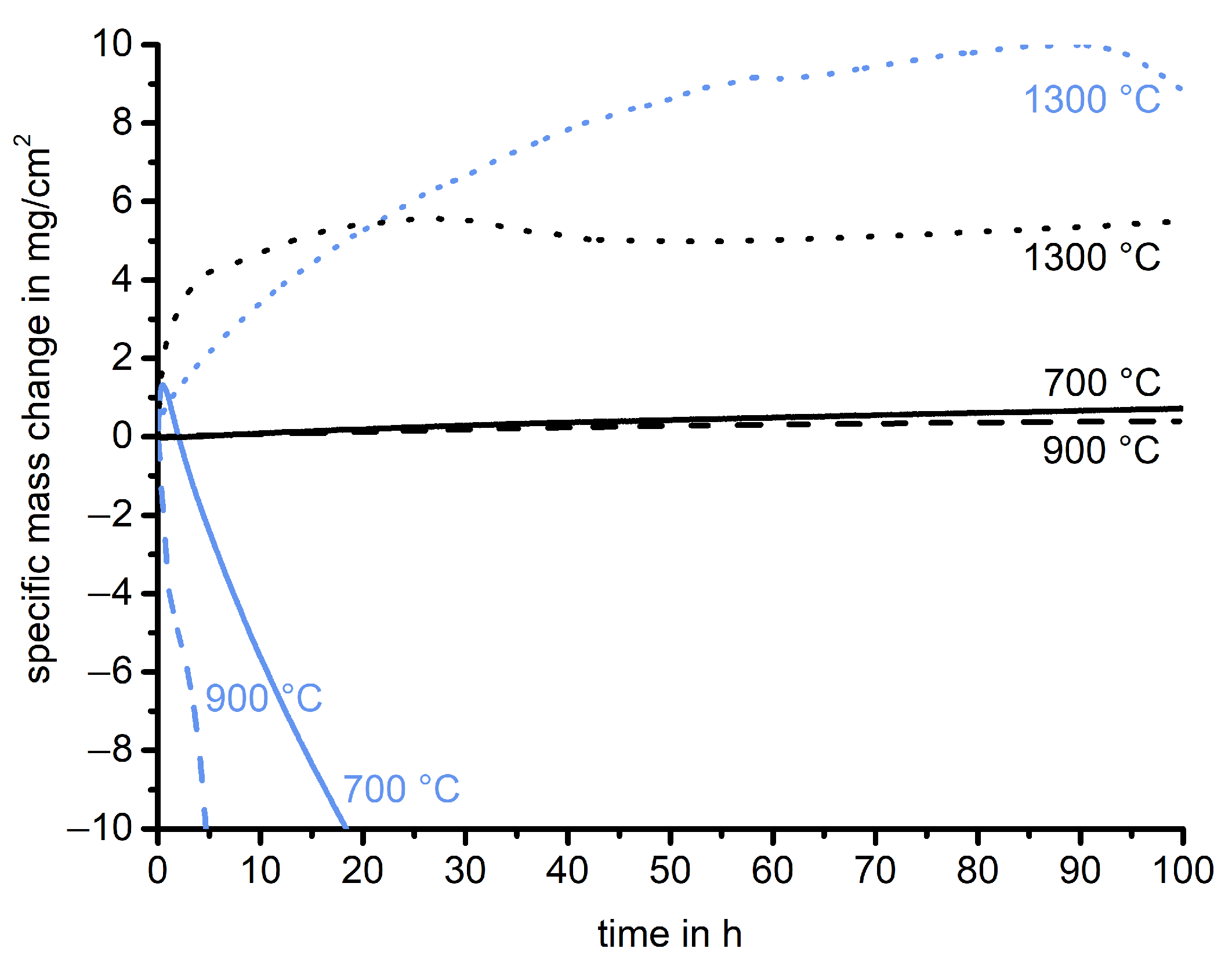
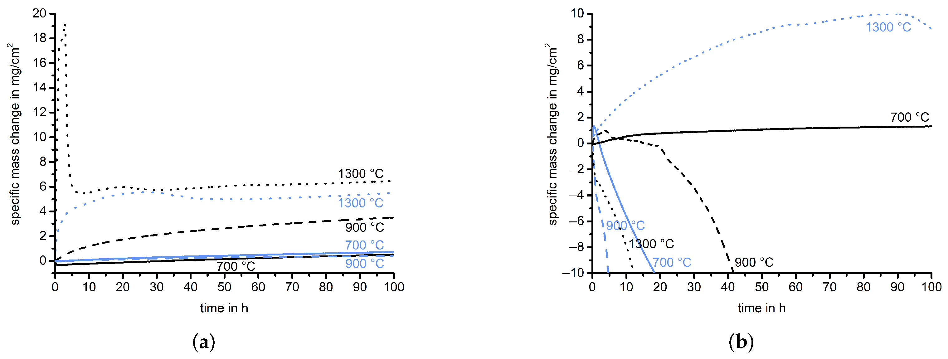
The mass change of the uncoated eutectic Mo-20.0Si-52.8Ti at 700 , 900 , and 1300 is shown in Figure 3. All measurements were carried out for 100 . At 700 and 900 , a minimal mass gain (less than 1 mg cm−2) is observed, which is comparable to the mass increase after cyclic oxidation at 800 [16]. At 1300 , a higher mass gain of about 5 mg cm−2 is observed, the major part of which takes place in the first 10 . After 30 a mass loss is observed, which can be attributed to either the evaporation of volatile species or the spallation of oxides. Since Mo is completely missing from the oxide scale but also not enriched underneath, the observed mass loss is assigned to the evaporation of MoO. This finding is further supported by the microstructure of the substrate, reflected in the Ti and Si distribution in the inner part of the 120 μm thick oxide scale after oxidation at 1300 . This layer also includes an outer TiO2 (tetragonal, P42/mnm, 136) layer about 40 μm thick. Below the oxide scale, the nitridation of the substrate material can be seen in the EPMA maps (see Figure 4).
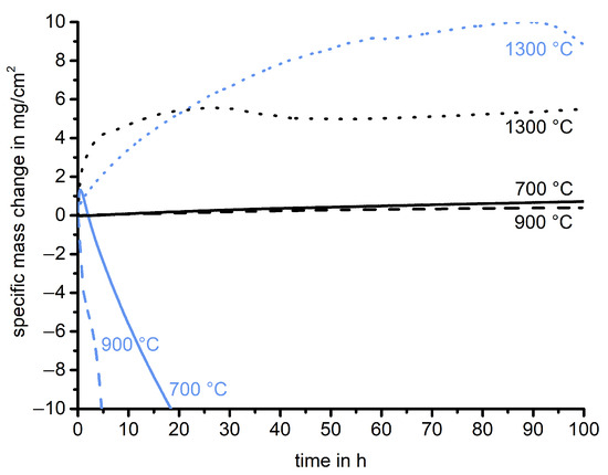
Figure 3.
Overview of the thermogravimetric analysis of the uncoated Mo-Si-Ti alloys at 700 °C (continuous line), 900 °C (dashed line), and 1300 °C (dotted line) in synthetic air for 100 h. The mass change of the eutectic Mo-20.0Si-52.8Ti is shown in black and that of the eutectoid Mo-21.0Si-34.0Ti is shown in light blue.

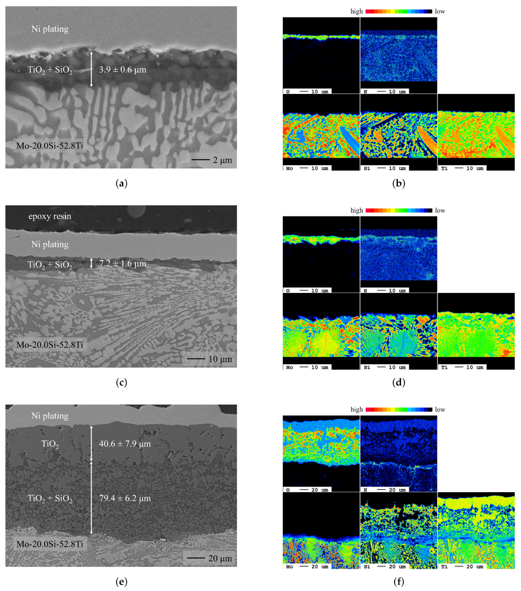
Figure 4.
BSE images (left) and EPMA maps (right) of the oxides formed on the eutectic alloy after oxidation at 700 °C, 900 °C, and 1300 °C in synthetic air for 100 h. The BSE images and the corresponding EPMA maps vary in magnification. (a) Oxidized Mo-20.0Si-52.8Ti (700 °C). (b) Oxidized Mo-20.0Si-52.8Ti (700 °C). (c) Oxidized Mo-20.0Si-52.8Ti (900 °C). (d) Oxidized Mo-20.0Si-52.8Ti (900 °C). (e) Oxidized Mo-20.0Si-52.8Ti (1300 °C). (f) Oxidized Mo-20.0Si-52.8Ti (1300 °C).
At intermediate temperatures (700 and 900 ), the fine microstructure of the eutectic alloy results in short diffusion paths for Si and Ti. This leads to the formation of a mixed TiO and SiO (trigonal, P321, 152) layer, which is about twice as thick on the sample oxidized at 900 (about 10 μm) compared to the one grown at 700 (cf. Figure 4). Nevertheless, the specific mass increase of the sample oxidized at 900 is lower than that of the sample oxidized at 700 (see Figure 3). This shows that at 900 , the evaporation of MoO already plays a major role and the changing weight gain cannot be described by simple kinetics. The EPMA maps show that SiO tends to be present at the oxide/substrate interface, whereas TiO is found in the outer part of the oxide scale. Under the oxide scale, Ti nitrides are present. Nitridation occurs during oxidation at 700 and 900 but is more pronounced at 900 (see Figure 4).
After oxidation at each of the three temperatures, the oxide layers consist of a mixture of TiO and SiO. This specific mixture is crucial for oxidation protection, as pure TiO is unable to form a protective oxide layer due to its high diffusion coefficient for oxygen [18] and its susceptibility to cracking [55]. The slow growth due to the presence of SiO even allows outward diffusion of TiO at 1300 , an oxide that usually grows inwards due to its high oxygen diffusivity [56].
The mass change curves of the uncoated Ti-lean eutectoid Mo-21.0Si-34.0Ti at 700 , 900 , and 1300 are shown in Figure 3 in light blue. The pesting resistance previously observed in the Ti-rich eutectic Mo-20.0Si-52.8Ti alloy is not evident in the eutectoid composition. A catastrophic weight loss is observed at 700 and 900 , which is in accordance with the oxidation behavior observed during cyclic oxidation at 800 [16]. As Mo can form two different oxides, there is an onset of mass loss during oxidation at 700 . The preliminary formation of TiO, SiO, and MoO leads to an initial increase in mass, followed by catastrophic weight loss due to the formation of MoO. At 1300 , the final mass gain of around 9 mg cm−2 is about twice as high as for the eutectic alloy.
The oxide layers found in the cross-sections of the eutectoid Mo-21.0Si-34.0Ti oxidized at 700 (see Figure 5a) and 900 (see Figure 5c) reflect the substantial weight loss, as both oxide layers consist of a porous mixture of TiO and SiO. This mixture is non-protective and cannot suppress the pesting of Mo. In addition, lateral cracks and other defects are visible within the oxide layer, leading to delamination and spallation. Compared to the eutectic alloy, the eutectoid alloy contains about 20 more Mo. Thus, when the volatile MoO evaporates, it creates porosity within the oxide layer, which allows the continuous transport of oxygen to the metal interface, leading to further oxidation (see Figure 6).
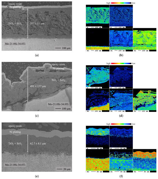
Figure 5.
BSE images (left) and EPMA maps (right) of the oxides formed on the eutectoid alloy after oxidation at 700 °C, 900 °C, and 1300 °C in synthetic air for 100 h. The BSE images and the corresponding EPMA maps vary in magnification. (a) Oxidized Mo-21.0Si-34.0Ti (700 ). (b) Oxidized Mo-21.0Si-34.0Ti (700 ). (c) Oxidized Mo-21.0Si-34.0Ti (900 ). (d) Oxidized Mo-21.0Si-34.0Ti (900 ). (e) Oxidized Mo-21.0Si-34.0Ti (1300 ). (f) Oxidized Mo-21.0Si-34.0Ti (1300 ).
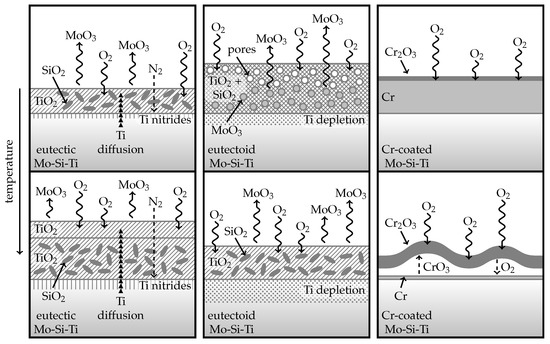
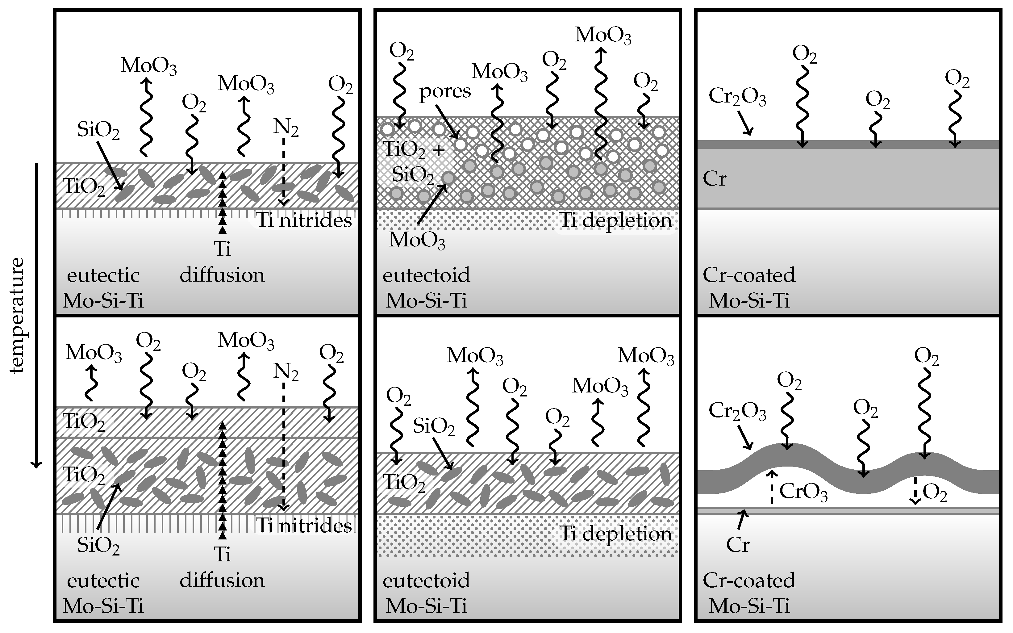
Figure 6.
Thermal progression of the oxidation mechanisms of the uncoated and Cr-coated Mo-Si-Ti alloys.
At 1300 , the oxidation behavior of the eutectoid alloy changes, and despite a higher mass gain, the formed oxide scale is thinner (see Figure 5e) than on the eutectic alloy (cf. Figure 4e). The accelerated formation of MoO no longer hinders the development of dense oxide layers, consisting mainly of TiO with small inclusions of SiO (see Figure 5f), which subsequently decelerate the evaporation of MoO in the further course of the oxidation. When MoO evaporates, titanium potentially diffuses into the pores, creating a large Ti-depletion zone underneath the oxide (see Figure 5f). In this Ti-depletion zone, Si is strongly enriched, and grain coarsening occurs, which has been shown not to affect the oxidation behavior of the eutectic alloy [17]. A dense, continuous SiO layer potentially forms at the metal interface, which lowers the oxygen partial pressure and suppresses the detrimental MoO formation. In many publications, the effect of these silica layers is described, along with the fact that they are difficult to identify [51,57,58]. These findings confirm that the ratio of different elements plays a crucial role in providing adequate oxidation resistance.
3.2.2. Cr-Coated Mo-Si-Ti Alloys
Figure 7 shows the mass change curves of the Cr-coated eutectic Mo-20.0Si-52.8Ti and eutectoid Mo-21.0Si-34.0Ti at 700 , 900 , and 1300 , along with the curves of the uncoated substrates for comparison. In the case of the eutectic alloy, which already showed slow kinetics at intermediate temperatures, the coated sample shows kinetics comparable to the uncoated sample at 700 . However, at 900 , the mass increase of the chromized sample is even notably higher than that of the uncoated eutectic alloy. After increasing the temperature even higher to 1300 , the mass change of the eutectic alloy undergoes a significant transformation, with an initial rapid mass gain followed by a rapid decrease, eventually converging to a weight gain similar to that of the uncoated sample. At 700 , a slow mass gain can be observed for both coated alloys, signifying a substantial improvement for the intrinsically inferior eutectoid alloy, which experiences catastrophic mass loss when uncoated. The onset of the strong mass loss at 900 is delayed by 20 for the Cr-coated eutectoid alloy compared to the uncoated substrate. In contrast, the oxidation behavior at 1300 is not improved by the coating and the sample undergoes a drastic mass loss.
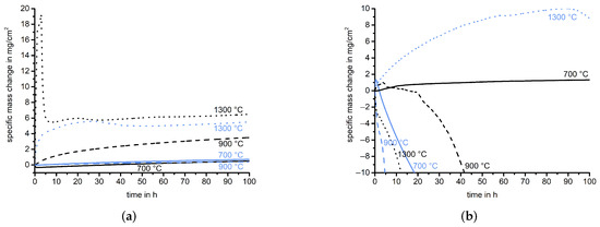
Figure 7.
Overview of the thermogravimetric analysis of the Cr-coated Mo-Si-Ti alloys at 700 (continuous line), 900 (dashed line), and 1300 (dotted line) in synthetic air for 100 . The mass change of the Cr-coated samples is shown in black and for comparison, the curves of the uncoated samples are shown in light blue. (a) Cr-coated Mo-20.0Si-58.2Ti. (b) Cr-coated Mo-21.0Si-34.0Ti.
A protective CrO (trigonal, Rc, 167) layer is formed on the Cr-coated eutectic samples during oxidation at 700 and 900 . Despite a comparable increase in mass, the oxide layer on the Cr-coated sample (see Figure 8a) is significantly thinner compared to the oxide layer formed on the uncoated sample after oxidation at 700 (see Figure 4a). This is due to the applied Cr coating, which inhibits the formation of volatile oxides such as MoO (cf. Figure 6). The mass gain of the Cr-coated eutectic alloy at 900 is higher than that of the uncoated sample because the formed CrO layer, about 30 μm (see Figure 8c), is more than three times thicker than that on the uncoated eutectic Mo-20.0Si-52.8Ti and delaminates from the substrate [59,60,61,62]. This is caused by compressive growth stresses within the scale owing to the volume change during oxidation, with a Pilling–Bedworth (P-B) ratio of 2, along with cation and anion transport. These factors lead to the formation of gaps in which the countertransport of oxygen and chromium occurs [63]. As for the uncoated alloys, at both temperatures, Ti nitrides are visible in the EPMA maps. However, the location of these nitrides indicates that they had already formed during pack cementation.
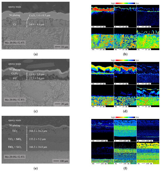
Figure 8.
BSE images (left) and EPMA maps (right) of the oxides formed on the Cr-coated eutectic alloy after oxidation at 700 , 900 , and 1300 in synthetic air for 100 . The BSE images and the corresponding EPMA maps vary in magnification. (a) Oxidized Cr-coated Mo-20.0Si-52.8Ti (700 ). (b) Oxidized Cr-coated Mo-20.0Si-52.8Ti (700 ). (c) Oxidized Cr-coated Mo-20.0Si-52.8Ti (900 ). (d) Oxidized Cr-coated Mo-20.0Si-52.8Ti (900 ). (e) Oxidized Cr-coated Mo-20.0Si-52.8Ti (1300 ). (f) Oxidized Cr-coated Mo-20.0Si-52.8Ti (1300 ).
The remaining Cr reservoir observed on the Cr-coated eutectic alloy oxidized at 700 is not evident on the sample oxidized at 900 . The depletion of Cr can be attributed to the formation of a significantly thicker oxide layer and the volatilization of CrO [60,64]. However, since the vapor pressure of CrO is not sufficient to account for the mass losses observed in dry air [65] and since CrO is the primary gaseous species that exists over solid CrO [65], the mass loss occurs via the following mechanism [66]:
Additional mechanisms contribute to the depletion of Cr reservoirs. At high temperatures, Cr metal can evaporate from the oxide scale through lattice and grain boundary diffusion within the chromium oxide. Furthermore, depending on the microstructure of the oxide, gaseous transport through porosities and microcracks within the oxide scale is also possible [67,68].
The oxide layer formed on the Cr-coated eutectic alloy during oxidation at 1300 (see Figure 8e) is considerably thicker than the layer formed on the uncoated sample (see Figure 4e) and has a different morphology. Small, discontinuous CrO particles that no longer provide oxidation resistance suggest the formation and subsequent delamination and spallation of CrO. This finding is further supported by the steep mass gain followed by a rapid mass loss in the first 5 of oxidation. Subsequently, the Si depletion zone below the bcc Cr layer, visible in the EPMA map of the as-coated sample (cf. Figure 1b), leads to the formation of a non-protective outwards-growing TiO layer, whereas the internal oxidation leads to inward-growing oxide scales consisting of mixed TiO and SiO.
During oxidation of the Cr-coated eutectoid sample at 700 (see Figure 9a), a protective CrO layer forms on top of a remaining Cr reservoir, as observed on the Cr-coated eutectic sample (see Figure 6). The deformation and delamination of the oxide layer on the Cr-coated eutectic alloy at 900 (see Figure 8c) already occurs in the eutectoid alloy at 700 . As for the Cr-coated eutectic sample, below the CrO layer, a nitridation zone is detected via EPMA mapping.
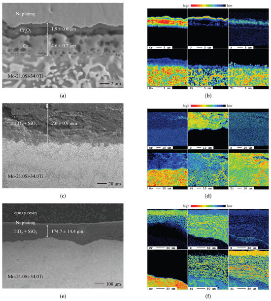
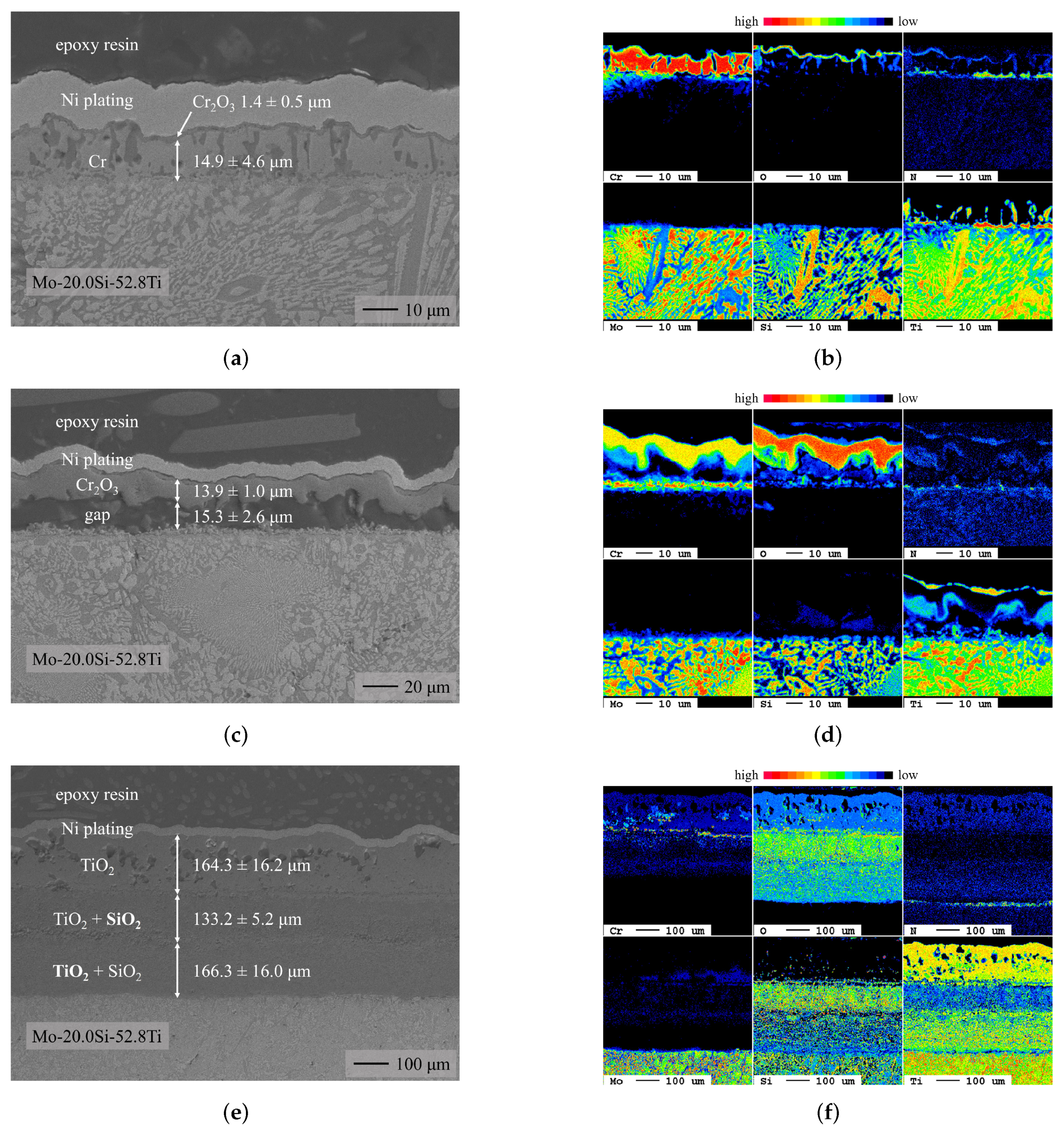
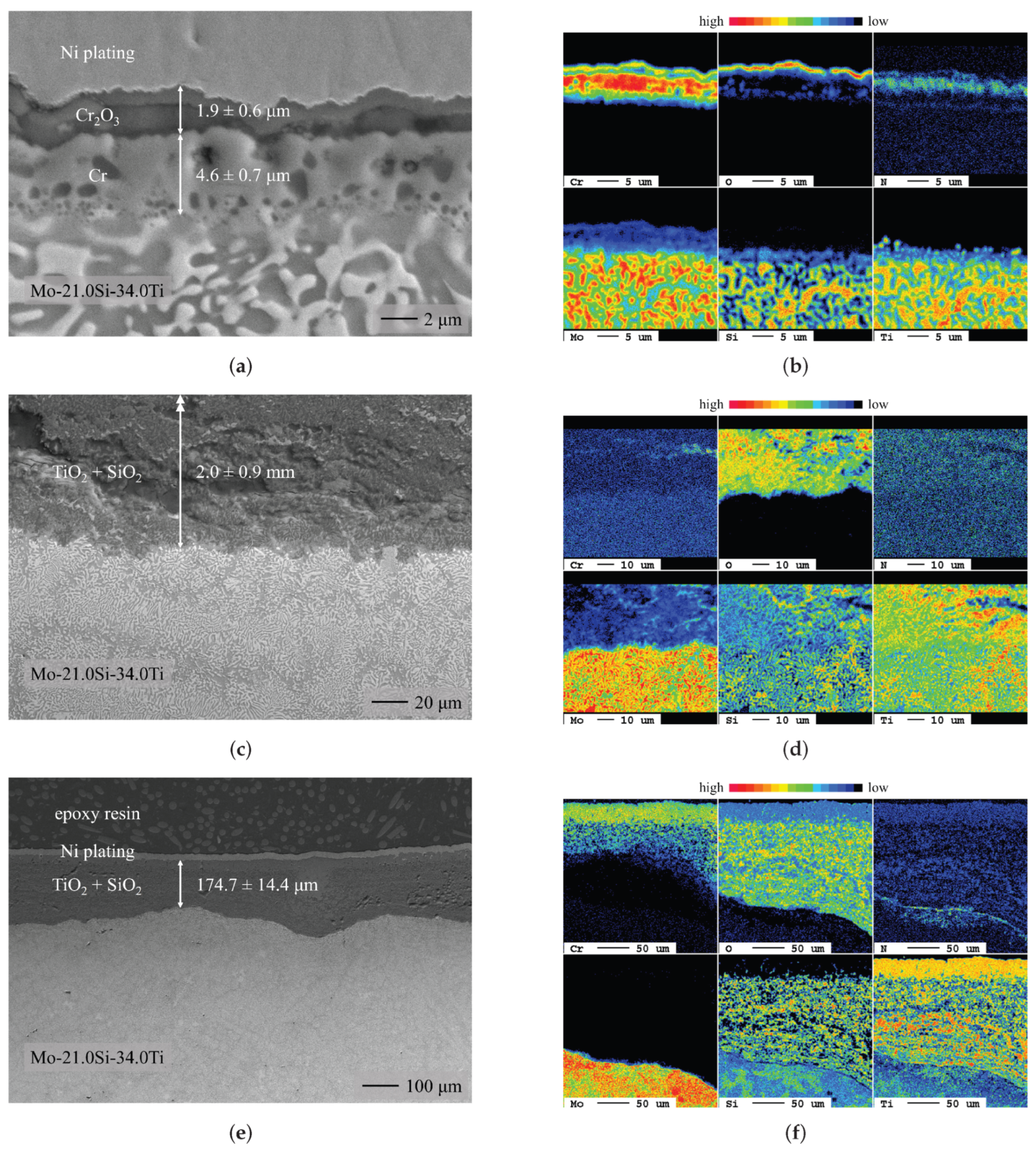
Figure 9.
BSE images (left) and EPMA maps (right) of the oxides formed on the Cr-coated eutectoid alloy after oxidation at 700 , 900 , and 1300 in synthetic air for 100 . The BSE images and the corresponding EPMA maps vary in magnification. In (c), the formed oxide layer is too thick to be visible in a BSE image. Therefore, only the lower section of the oxide layer is visible, but the indicated thickness refers to the entire layer. (a) Oxidized Cr-coated Mo-21.0Si-34.0Ti (700 ). (b) Oxidized Cr-coated Mo-21.0Si-34.0Ti (700 ). (c) Oxidized Cr-coated Mo-21.0Si-34.0Ti (900 ). (d) Oxidized Cr-coated Mo-21.0Si-34.0Ti (900 ). (e) Oxidized Cr-coated Mo-21.0Si-34.0Ti (1300 ). (f) Oxidized Cr-coated Mo-21.0Si-34.0Ti (1300 ).
Since the bcc Cr layer deposited on the eutectoid Mo-21.0Si-34.0Ti is notably thinner (see Figure 1c) and the Mo content of the alloy is notably higher, the formation of a protective CrO layer at 900 , previously observed with the Ti-rich eutectic Mo-20.0Si-52.8Ti alloy, is not evident for the eutectoid composition. The slow oxidation kinetics during the first 20 suggest the initial formation of a protective CrO layer. The subsequent mass loss is comparable to that of the uncoated eutectoid alloy. Thus, the substrate material is abruptly exposed to the oxidizing atmosphere, leading to a notably thicker oxide layer on the Cr-coated Mo-21.0Si-34.0Ti (see Figure 9c) compared to the uncoated substrate (see Figure 5c).
In comparison with the uncoated sample (cf. Figure 5e), the formed oxide layer is more than twice as thick and contains small, discontinuous CrO particles that no longer provide oxidation resistance (see Figure 9e). As for the uncoated sample, a thin nitridation zone can be seen below the oxide layer.
4. Summary and Conclusions
To sum up, at intermediate temperatures (700 and 900 ), the Cr diffusion coatings demonstrated a promising approach to improve the oxidation behavior of the eutectic Mo-20.0Si-52.8Ti and the eutectoid Mo-21.0Si-34.0Ti. To further improve the oxidation resistance of the Cr-coated eutectoid alloy, the deposition of thicker diffusion coatings would be necessary. At 1300 , the applied Cr diffusion coatings are depleted and overgrown too fast to provide adequate protection. Therefore, in this temperature range, alloying with Cr would be a more promising approach to improve the oxidation behavior [69].
- Chromium diffusion coatings were successfully applied to two ternary Mo-Si-Ti alloys (eutectic Mo-20.0Si-52.8Ti and eutectoid Mo-21.0Si-34.0Ti).
- During oxidation of the uncoated eutectic alloy at 700 and 900 , a thin oxide layer consisting of mixed TiO and SiO formed. At 1300 , a higher mass gain and the formation of a duplex scale, consisting of an outer TiO and an inner TiO/SiO layer, were detected.
- The uncoated eutectoid alloy exhibited catastrophic oxidation behavior during the oxidation tests at 700 and 900 . At 1300 , a dense protective oxide layer, consisting of TiO and a thin continuous SiO layer at the oxide/substrate interface, decelerated oxide growth.
- The oxidation behavior of the Cr-coated eutectic Mo-20.0Si-52.8Ti alloy was comparable to the behavior of the uncoated samples but at 700 and 900 , the evaporation of volatile Mo species was prevented by the CrO formation.
- During the oxidation of the Cr-coated eutectoid Mo-21.0Si-34.0Ti at 700 , a minimal mass gain was observed, which was a significant improvement compared to the catastrophic oxidation observed previously. At higher temperatures, the Cr reservoir was depleted and the CrO failed during the oxidation experiment; therefore, the oxidation behavior was mainly determined by the composition of the underlying substrate.
Author Contributions
K.B.: Methodology, investigation, writing—original draft preparation, visualization; F.H.: Resources, writing—review and editing; C.O.: writing—review and editing, supervision; A.S.U.: Conceptualization, writing—review and editing, supervision; M.H.: Writing—review and editing, project administration, funding acquisition; M.C.G.: Conceptualization, writing—review and editing, supervision, project administration, funding acquisition. All authors have read and agreed to the published version of the manuscript.
Funding
This work was supported by the Research Training Group 2561 “MatCom-ComMat: Materials Compounds from Composite Materials for Applications in Extreme Conditions” (project number 413956820) funded by the Deutsche Forschungsgemeinschaft (DFG).
Data Availability Statement
The data that support the findings of this study are available from the corresponding author upon reasonable request.
Acknowledgments
The authors thank Gerald Schmidt for the EPMA measurements and Mathias Röhrig for the technical support.
Conflicts of Interest
The authors declare no conflict of interest.
Appendix A. XRD Analysis
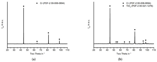
Figure A1.
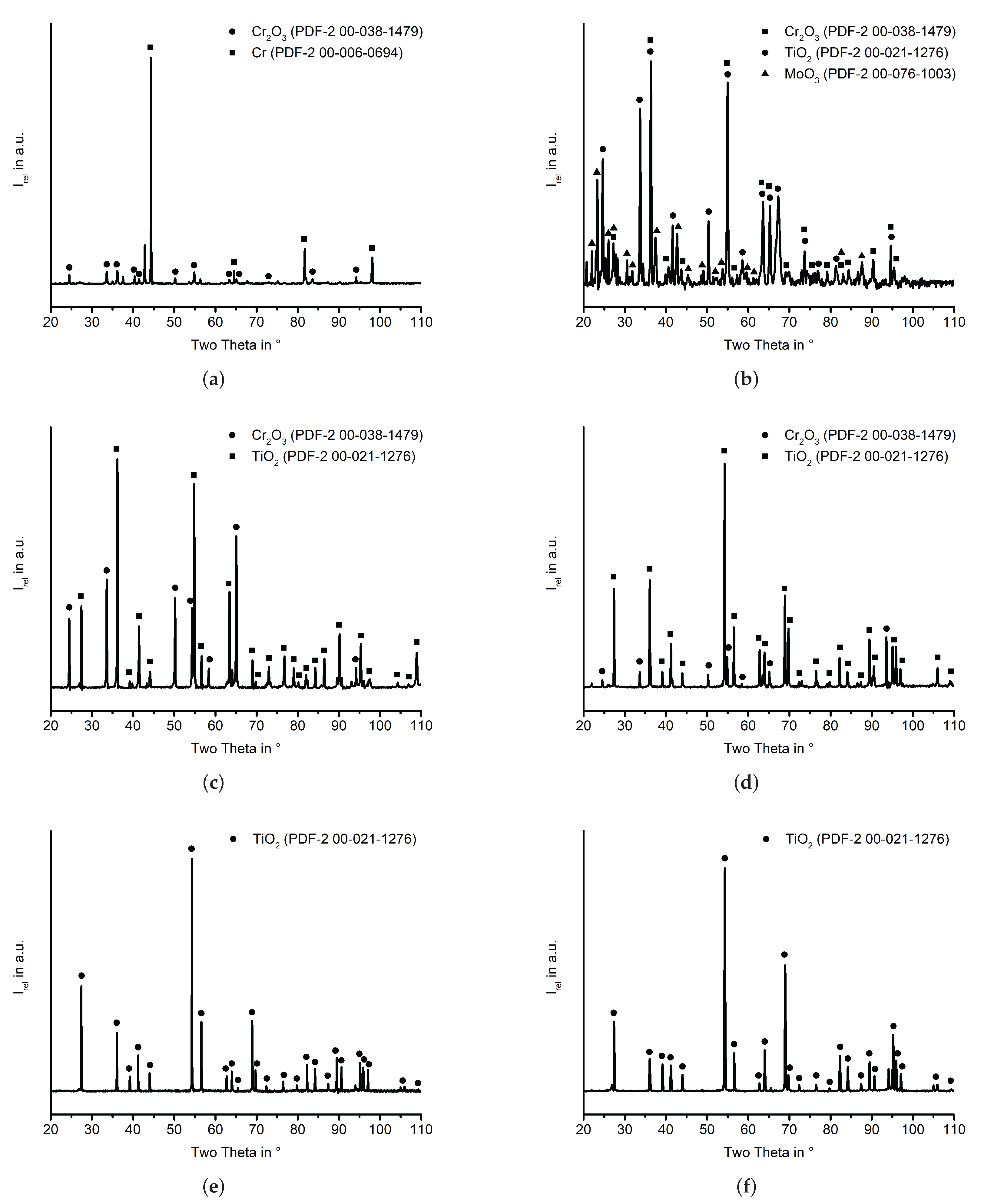
XRD patterns of the different phases formed on the Mo-Si-Ti substrates after pack cementation. (a) Cr-coated Mo-20.0Si-52.8Ti. (b) Cr-coated Mo-21.0Si-34.0Ti. The given database entry yields the closest match to the experimental results, additional databases were then used to identify all reflexes.
Figure A1.
XRD patterns of the different phases formed on the Mo-Si-Ti substrates after pack cementation. (a) Cr-coated Mo-20.0Si-52.8Ti. (b) Cr-coated Mo-21.0Si-34.0Ti. The given database entry yields the closest match to the experimental results, additional databases were then used to identify all reflexes.
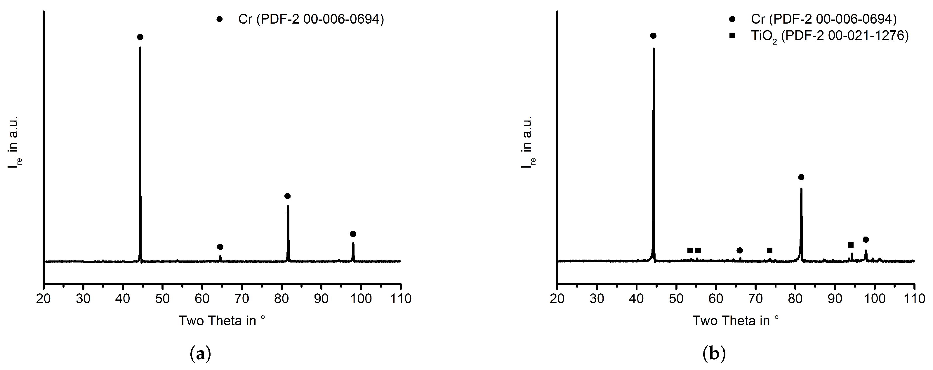
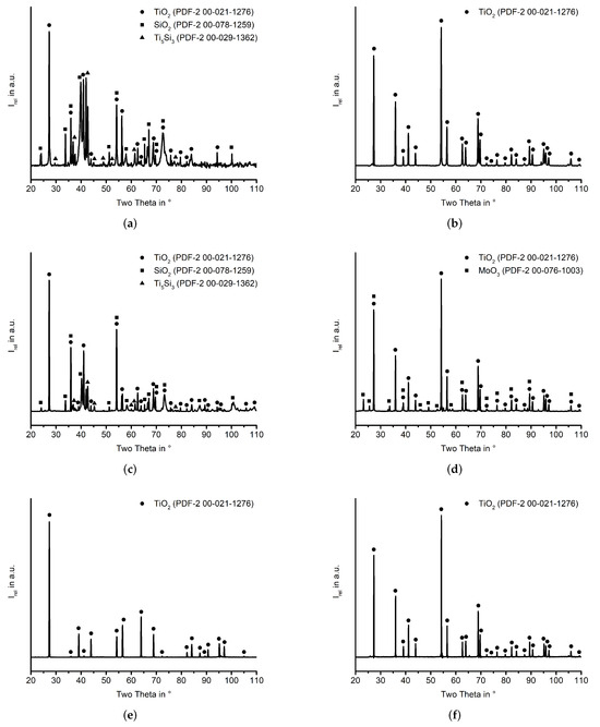
Figure A2.
XRD spectra of the different oxides formed on the uncoated Mo-Si-Ti substrates. In (d), the redeposition of MoO on the sample surface may have occurred during cooling. This species was not found in the cross-section because it is water-soluble and therefore removed during cross-section preparation. (a) Oxidized Mo-20.0Si-52.8Ti (700 ). (b) Oxidized Mo-21.0Si-34.0Ti (700 ). (c) Oxidized Mo-20.0Si-52.8Ti (900 ). (d) Oxidized Mo-21.0Si-34.0Ti (900 ). (e) Oxidized Mo-20.0Si-52.8Ti (1300 ). (f) Oxidized Mo-21.0Si-34.0Ti (1300 ). The given database entry yields the closest match to the experimental results, additional databases were then used to identify all reflexes.
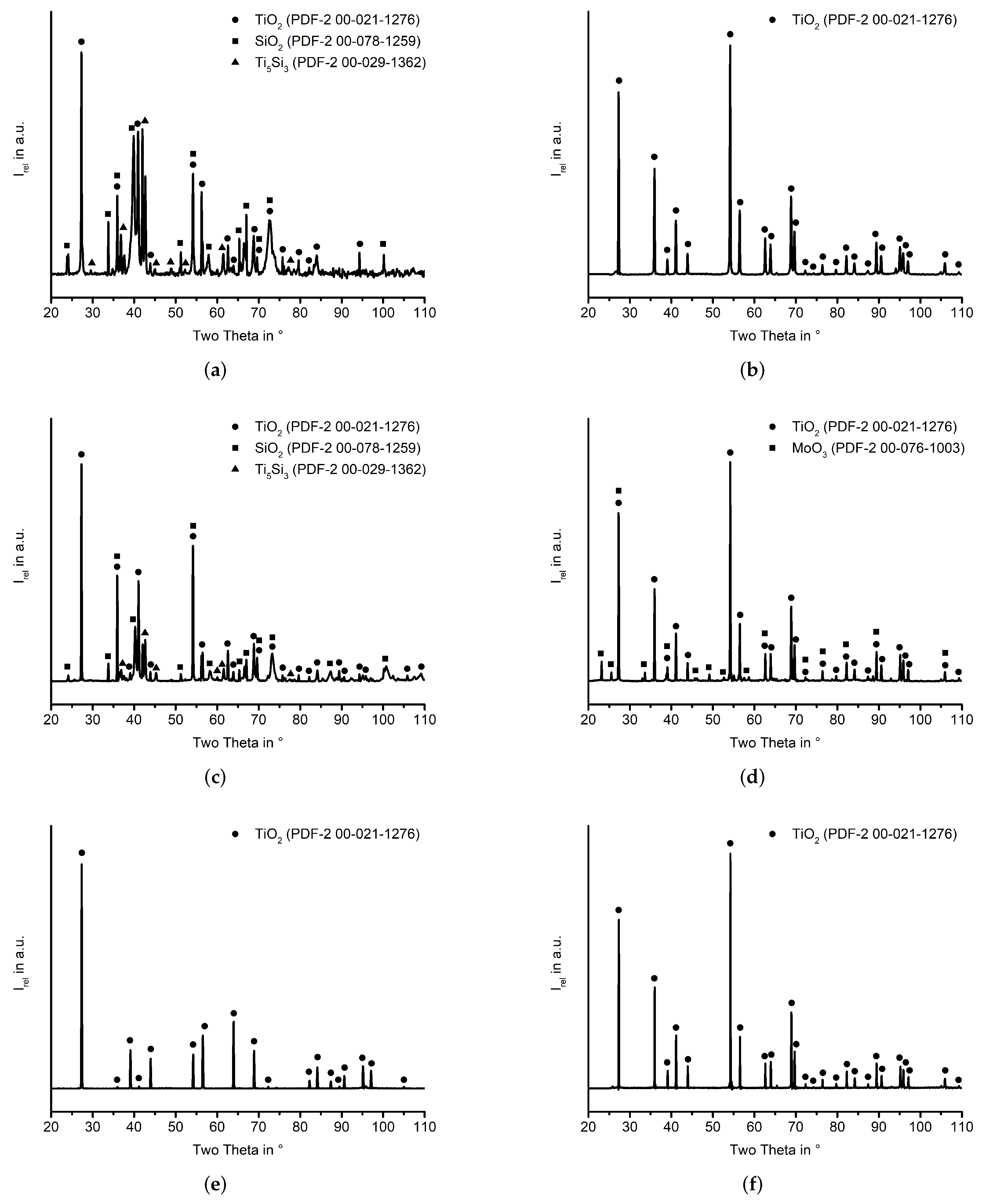
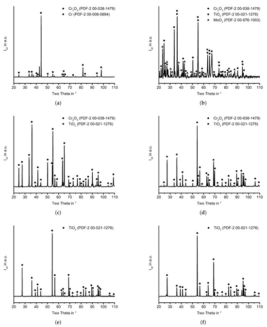
Figure A3.
XRD spectra of the different oxides formed on the Cr-coated Mo-Si-Ti substrates. In (d), the redeposition of MoO on the sample surface may have occurred during cooling. This species was not found in the cross-section because it is water-soluble and therefore removed during cross-section preparation. (a) Oxidized Cr-coated Mo-20.0Si-52.8Ti (700 ). (b) Oxidized Cr-coated Mo-21.0Si-34.0Ti (700 ). (c) Oxidized Cr-coated Mo-20.0Si-52.8Ti (900 ). (d) Oxidized Cr-coated Mo-21.0Si-34.0Ti (900 ). (e) Oxidized Cr-coated Mo-20.0Si-52.8Ti (1300 ). (f) Oxidized Cr-coated Mo-21.0Si-34.0Ti (1300 ). The given database entry yields the closest match to the experimental results, additional databases were then used to identify all reflexes.
References
- Perepezko, J.H. The hotter the engine, the better. Science 2009, 326, 1068–1069. [Google Scholar] [CrossRef]
- Dimiduk, D.M.; Perepezko, J.H. Mo-Si-B alloys: Developing a revolutionary turbine-engine material. MRS Bull. 2003, 28, 639–645. [Google Scholar] [CrossRef]
- Lemberg, J.A.; Ritchie, R.O. Mo-Si-B alloys for ultrahigh-temperature structural applications. Adv. Mater. 2012, 24, 3445–3480. [Google Scholar] [CrossRef] [PubMed]
- Parthasarathy, T.; Mendiratta, M.; Dimiduk, D. Oxidation mechanisms in Mo-reinforced Mo5SiB2 (T2)-Mo3Si alloys. Acta Mater. 2002, 50, 1857–1868. [Google Scholar] [CrossRef]
- Bürgel, R.; Maier, H.J.; Niendorf, T. Handbuch Hochtemperatur-Werkstofftechnik: Grundlagen, Werkstoffbeanspruchungen, Hochtemperaturlegierungen und -Beschichtungen; Springer: Berlin/Heidelberg, Germany, 2011. [Google Scholar]
- Reyhani, M.R.; Alizadeh, M.; Fathi, A.; Khaledi, H. Turbine blade temperature calculation and life estimation—A sensitivity analysis. Propuls. Power Res. 2013, 2, 148–161. [Google Scholar] [CrossRef]
- Mazur, Z.; Luna-Ramirez, A.; Juárez-Islas, J.; Campos-Amezcua, A. Failure analysis of a gas turbine blade made of Inconel 738LC alloy. Eng. Fail. Anal. 2005, 12, 474–486. [Google Scholar] [CrossRef]
- Jéhanno, P.; Heilmaier, M.; Kestler, H. Characterization of an industrially processed Mo-based silicide alloy. Intermetallics 2004, 12, 1005–1009. [Google Scholar] [CrossRef]
- Erickson, G.L. A new, third-generation, single-crystal, casting superalloy. JOM 1995, 47, 36–39. [Google Scholar] [CrossRef]
- Azim, M.A.; Burk, S.; Gorr, B.; Christ, H.J.; Schliephake, D.; Heilmaier, M.; Bornemann, R.; Bolívar, P.H. Effect of Ti (macro-)alloying on the high-temperature oxidation behavior of ternary Mo-Si-B alloys at 820–1300 °C. Oxid. Met. 2013, 80, 231–242. [Google Scholar] [CrossRef]
- Schliephake, D.; Azim, M.A.; von Klinski-Wetzel, K.; Gorr, B.; Christ, H.J.; Bei, H.; George, E.P.; Heilmaier, M. High-temperature creep and oxidation behavior of Mo-Si-B alloys with high Ti contents. Metall. Mater. Trans. A 2014, 45, 1102–1111. [Google Scholar]
- Schmitt, A.; Kumar, K.S.; Kauffmann, A.; Li, X.; Stein, F.; Heilmaier, M. Creep of binary Fe-Al alloys with ultrafine lamellar microstructures. Intermetallics 2017, 90, 180–187. [Google Scholar] [CrossRef]
- Rioult, F.; Imhoff, S.; Sakidja, R.; Perepezko, J. Transient oxidation of Mo-Si-B alloys: Effect of the microstructure size scale. Acta Mater. 2009, 57, 4600–4613. [Google Scholar] [CrossRef]
- Maruyama, K.; Yamamoto, R.; Nakakuki, H.; Fujitsuna, N. Effects of lamellar spacing, volume fraction and grain size on creep strength of fully lamellar TiAl alloys. Mater. Sci. Eng. A 1997, 239, 419–428. [Google Scholar] [CrossRef]
- Hasemann, G.; Kaplunenko, D.; Bogomol, I.; Krüger, M. Near-eutectic ternary Mo-Si-B alloys: Microstructures and creep properties. JOM 2016, 68, 2847–2853. [Google Scholar] [CrossRef]
- Schliephake, D.; Kauffmann, A.; Cong, X.; Gombola, C.; Azim, M.; Gorr, B.; Christ, H.J.; Heilmaier, M. Constitution, oxidation and creep of eutectic and eutectoid Mo-Si-Ti alloys. Intermetallics 2019, 104, 133–142. [Google Scholar] [CrossRef]
- Obert, S.; Kauffmann, A.; Seils, S.; Schellert, S.; Weber, M.; Gorr, B.; Christ, H.J.; Heilmaier, M. On the chemical and microstructural requirements for the pesting-resistance of Mo-Si-Ti alloys. J. Mater. Res. Technol. 2020, 9, 8556–8567. [Google Scholar] [CrossRef]
- Unnam, J.; Shenoy, R.; Clark, R. Oxidation of commercial purity titanium. Oxid. Met. 1986, 26, 231–252. [Google Scholar] [CrossRef]
- Dai, J.; Zhu, J.; Chen, C.; Weng, F. High temperature oxidation behavior and research status of modifications on improving high temperature oxidation resistance of titanium alloys and titanium aluminides: A review. J. Alloys Compd. 2016, 685, 784–798. [Google Scholar] [CrossRef]
- Bianco, R.; Rapp, R.A. Pack cementation diffusion coatings. In Metallurgical and Ceramic Protective Coatings; Springer: Berlin/Heidelberg, Germany, 1996; pp. 236–260. [Google Scholar]
- Ito, K.; Numakura, H.; Hayashi, T.; Yokobayashi, M.; Murakami, T. Oxidation protective silicide coating on Mo-Si-B alloys. Metall. Mater. Trans. A 2005, 36, 627–636. [Google Scholar] [CrossRef]
- Sakidja, R.; Park, J.; Hamann, J.; Perepezko, J. Synthesis of oxidation resistant silicide coatings on Mo-Si-B alloys. Scr. Mater. 2005, 53, 723–728. [Google Scholar] [CrossRef]
- Tang, Z.; Thom, A.J.; Kramer, M.; Akinc, M. Characterization and oxidation behavior of silicide coating on multiphase Mo-Si-B alloy. Intermetallics 2008, 16, 1125–1133. [Google Scholar] [CrossRef]
- Perepezko, J.H.; Sakidja, R. Oxidation-resistant coatings for ultra-high-temperature refractory Mo-based alloys. JOM 2010, 62, 13–19. [Google Scholar] [CrossRef]
- Lange, A.; Heilmaier, M.; Sossamann, T.A.; Perepezko, J.H. Oxidation behavior of pack-cemented Si-B oxidation protection coatings for Mo-Si-B alloys at 1300 °C. Surf. Coat. Technol. 2015, 266, 57–63. [Google Scholar] [CrossRef]
- Schliephake, D.; Gombola, C.; Kauffmann, A.; Heilmaier, M.; Perepezko, J.H. Enhanced oxidation resistance of Mo-Si-B-Ti alloys by pack cementation. Oxid. Met. 2017, 88, 267–277. [Google Scholar] [CrossRef]
- Rioult, F.; Sekido, N.; Sakidja, R.; Perepezko, J.H. Aluminum pack cementation on Mo-Si-B alloys: Kinetics and lifetime prediction. J. Electrochem. Soc. 2007, 154, C692. [Google Scholar] [CrossRef]
- Choi, K.; Yang, W.; Baik, K.H.; Kim, Y.; Lee, S.; Park, J.S. Growth kinetics and isothermal oxidation behavior of aluminide pack coatings on a multiphase Mo-Si-B alloy. Oxid. Met. 2019, 92, 423–437. [Google Scholar] [CrossRef]
- Sakidja, R.; Rioult, F.; Werner, J.; Perepezko, J.H. Aluminum pack cementation of Mo-Si-B alloys. Scr. Mater. 2006, 55, 903–906. [Google Scholar] [CrossRef]
- Trzebiatowski, W.; Ploszek, H.; Lobzowski, J. X-ray analysis of chromium-molybdenum and chromium-tungsten alloys. Anal. Chem. 1947, 19, 93–95. [Google Scholar] [CrossRef]
- Rapp, R.A. Hot corrosion of materials: A fluxing mechanism? Corros. Sci. 2002, 44, 209–221. [Google Scholar] [CrossRef]
- Otsuka, N.; Rapp, R.A. The role of chromium in the hot corrosion of metals. ECS Trans. 2009, 16, 271–282. [Google Scholar] [CrossRef]
- Fauzi, F.; Kurniawan, T.; Salwani, M.; Bin, Y.; Harun, W. Chromium enrichment on P11 ferritic steel by pack cementation. MATEC Web Conf. 2016, 74, 00036. [Google Scholar] [CrossRef]
- Hänni, W.; Hintermann, H. Chemical vapour deposition of chromium. Thin Solid Film. 1977, 40, 107–114. [Google Scholar] [CrossRef]
- Hu, Y.; Peng, Y.; Hu, F.; He, F.; Guo, P. Anti-corrosion performance of chromium-coated steel in a carbon dioxide-saturated simulated oilfield brine. Int. J. Electrochem. Sci. 2017, 12, 5628–5635. [Google Scholar] [CrossRef]
- Leferink, R.; Huijbregts, W. Chromium diffusion coatings for the protection of low-alloy steel in a sulphidizing atmosphere. Corros. Sci. 1993, 35, 1235–1242. [Google Scholar] [CrossRef]
- Lin, N.M.; Xie, F.Q.; Zhou, J.; Zhong, T.; Wu, X.Q.; Tian, W. Microstructures and wear resistance of chromium coatings on P110 steel fabricated by pack cementation. J. Cent. South Univ. Technol. 2010, 17, 1155–1162. [Google Scholar] [CrossRef]
- Wang, Q.Y.; Behnamian, Y.; Luo, H.; Wang, X.Z.; Leitch, M.; Zeng, H.; Luo, J.L. Anticorrosion performance of chromized coating prepared by pack cementation in simulated solution with H2S and CO2. Appl. Surf. Sci. 2017, 419, 197–205. [Google Scholar] [CrossRef]
- Zou, J.; Xie, F.; Lin, N.; Yao, X.; Tian, W.; Tang, B. Formation of chromium coating and comparative examination on corrosion resistance with 13Cr steel in CO2-saturated simulated oilfield brine. Surf. Rev. Lett. 2013, 20, 1350041. [Google Scholar] [CrossRef]
- Gaillard-Allemand, B.; Vilasi, M.; Belmonte, T.; Rives, C.; Czerwiec, T.; Belnet, F.; Kerrec, O.; Michel, H. Passivation of nickel-base superalloy Inconel 690 by pack-cementation chromium coatings. Mater. Sci. Forum 2001, 369, 735–742. [Google Scholar] [CrossRef]
- Ledoux, X.; Vilasi, M.; Mathieu, S.; Pantiex, P.J.; Del-Gallo, P.; Wanger, M. Development of chromium and aluminum coatings on superalloys by pack-cementation technique. Adv. Mater. Res. 2011, 278, 491–496. [Google Scholar] [CrossRef]
- Mazille, H.M. Chemical vapour deposition of chromium onto nickel. Thin Solid Films 1980, 65, 67–74. [Google Scholar] [CrossRef]
- Holleman, A.F. Lehrbuch der Anorganischen Chemie; Walter de Gruyter GmbH & Co KG: Berlin, Germany, 2019. [Google Scholar]
- Murray, J. The Cr-Ti (chromium-titanium) system. Bull. Alloy Phase Diagr. 1981, 2, 174–181. [Google Scholar] [CrossRef]
- Yabe, H.; Kuji, T. Mechanically driven bcc TiCr alloy and its hydrogen solubility. J. Alloys Compd. 2005, 404, 533–536. [Google Scholar] [CrossRef]
- Liu, Z.; Welsch, G. Literature survey on diffusivities of oxygen, aluminum, and vanadium in alpha titanium, beta titanium, and in rutile. Metall. Trans. A 1988, 19, 1121–1125. [Google Scholar] [CrossRef]
- Amherd Hidalgo, A.; Frykholm, R.; Ebel, T.; Pyczak, F. Powder metallurgy strategies to improve properties and processing of titanium alloys: A review. Adv. Eng. Mater. 2017, 19, 1600743. [Google Scholar] [CrossRef]
- Maier, K.; Mehrer, H.; Rein, G. Self-diffusion in molybdenum. Int. J. Mater. Res. 1979, 70, 271–276. [Google Scholar] [CrossRef]
- Kroll, S.; Mehrer, H.; Stolwijk, N.; Herzig, C.; Rosenkranz, R.; Frommeyer, G. Titanium self-diffusion in the intermetallic compound γ-TiAl. Int. J. Mater. Res. 1992, 83, 591–595. [Google Scholar] [CrossRef]
- Mortimer, R.G. Physical Chemistry; Academic Press: Cambridge, MA, USA, 2000. [Google Scholar]
- Ulrich, A.S.; Pfizenmaier, P.; Solimani, A.; Glatzel, U.; Galetz, M.C. Improving the oxidation resistance of Cr-Si-based alloys by ternary alloying. Corros. Sci. 2020, 165, 108376. [Google Scholar] [CrossRef]
- Briant, C.; Wang, Z.; Chollocoop, N. Hydrogen embrittlement of commercial purity titanium. Corros. Sci. 2002, 44, 1875–1888. [Google Scholar] [CrossRef]
- Tal-Gutelmacher, E.; Eliezer, D. The hydrogen embrittlement of titanium-based alloys. JOM 2005, 57, 46–49. [Google Scholar] [CrossRef]
- Madina, V.; Azkarate, I. Compatibility of materials with hydrogen. Particular case: Hydrogen embrittlement of titanium alloys. Int. J. Hydrogen Energy 2009, 34, 5976–5980. [Google Scholar] [CrossRef]
- Gomes, J.; Huntz, A. Comparison of the kinetics and morphologic properties of titanium, Ti-1.5 Ni and Ti-2.5 Cu during oxidation in pure oxygen between 600 and 820 °C. Oxid. Met. 1980, 14, 471–498. [Google Scholar] [CrossRef]
- Epifano, E.; Monceau, D. Ellingham diagram: A new look at an old tool. Corros. Sci. 2023, 217, 111113. [Google Scholar] [CrossRef]
- Soleimani-Dorcheh, A.; Galetz, M. Oxidation and nitridation behavior of Cr-Si alloys in air at 1473 K. Oxid. Met. 2015, 84, 73–90. [Google Scholar] [CrossRef]
- Solimani, A.; Nguyen, T.; Zhang, J.; Young, D.J.; Schütze, M.; Galetz, M.C. Morphology of oxide scales formed on chromium-silicon alloys at high temperatures. Corros. Sci. 2020, 176, 109023. [Google Scholar] [CrossRef]
- Royer, L.; Ledoux, X.; Mathieu, S.; Steinmetz, P. On the oxidation and nitridation of chromium at 1300 °C. Oxid. Met. 2010, 74, 79–92. [Google Scholar] [CrossRef]
- Caplan, D.; Cohen, M. The volatilization of chromium oxide. J. Electrochem. Soc. 1961, 108, 438. [Google Scholar] [CrossRef]
- Gulbransen, E.A.; Andrew, K.F. Kinetics of the oxidation of chromium. J. Electrochem. Soc. 1957, 104, 334. [Google Scholar] [CrossRef]
- Lillerud, K.; Kofstad, P. On high temperature oxidation of chromium: I. Oxidation of annealed, thermally etched chromium at 800–1100 °C. J. Electrochem. Soc. 1980, 127, 2397. [Google Scholar] [CrossRef]
- Schütze, M. Stress effects in high temperature oxidation. Ref. Modul. Mater. Sci. Mater. Eng. 2016. [Google Scholar]
- Hagel, W.C. Factors controlling the high-temperature oxidation of chromium. J. Electrochem. Soc. 1962, 109, C78. [Google Scholar]
- Grimley, R.; Burns, R.; Inghram, M.G. Thermodynamics of the vaporization of Cr2O3: Dissociation energies of CrO, CrO2, and CrO3. J. Chem. Phys. 1961, 34, 664–667. [Google Scholar] [CrossRef]
- Graham, H.; Davis, H. Oxidation/Vaporization kinetics of Cr2O3. J. Am. Ceram. Soc. 1971, 54, 89–93. [Google Scholar] [CrossRef]
- Kofstad, P.; Lillerud, K. Chromium transport through Cr2O3 scales I. On lattice diffusion of chromium. Oxid. Met. 1982, 17, 177–194. [Google Scholar] [CrossRef]
- Lillerud, K.; Kofstad, P. Chromium transport through Cr2O3 scales II. Changes in scale morphology during high vacuum treatment of oxidized chromium specimens. Oxid. Met. 1982, 17, 195–203. [Google Scholar] [CrossRef]
- Hinrichs, F.; Kauffmann, A.; Tirunilai, A.S.; Schliephake, D.; Beichert, B.; Winkens, G.; Beck, K.; Ulrich, A.S.; Galetz, M.C.; Long, Z.; et al. A novel nitridation-and pesting-resistant Cr-Si-Mo alloy. Corros. Sci. 2022, 207, 110566. [Google Scholar] [CrossRef]

Disclaimer/Publisher’s Note: The statements, opinions and data contained in all publications are solely those of the individual author(s) and contributor(s) and not of MDPI and/or the editor(s). MDPI and/or the editor(s) disclaim responsibility for any injury to people or property resulting from any ideas, methods, instructions or products referred to in the content. |
© 2023 by the authors. Licensee MDPI, Basel, Switzerland. This article is an open access article distributed under the terms and conditions of the Creative Commons Attribution (CC BY) license (https://creativecommons.org/licenses/by/4.0/).