Abstract
In this paper, the magnetically tunable Goos–Hänchen (GH) shift of a reflected beam at terahertz frequencies is achieved by using a multilayer structure where three layers of anisotropic graphene are inserted. The enhanced GH shift phenomenon results from the local field enhancement owing to the excitation of graphene surface plasmon polaritons at the interface between two dielectric materials. By considering the quantum response of graphene, the GH shift can be switched from negative to positive by harnessing the anisotropic conductivity of graphene, and the GH shift can be actively tuned through the external magnetic field or by controlling the structural parameters. By setting appropriate magnetic field and structural parameters, we can obtain GH values of −140 microns to 220 microns in the terahertz band. This enhanced and tunable GH shift is promising for fabricating graphene-based terahertz shift devices and other applications in nanophotonics.
1. Introduction
The reflected beam does not intersect with the incident beam and the normal but rather has a small displacement on the reflected interface, which is often referred to as a Goos–Hänchen (GH) shift [1]. Thanks to its wide application in all optical switches [2], optical sensing [3], beam steering [4], precise measurement [5] and other fields, the GH shift has received widespread attention from researchers in the past few decades. Researchers have conducted extensive research on the enhancement and manipulation of the GH shift in various materials and different structures, such as monolayer phosphorene [6], metamaterials [7], photonic-magnonic crystals [8], temporally dispersive attenuative materials [9], photonic crystals [10,11] and so on. At the same time, researchers are also trying to combine specific mechanisms to achieve the enhancement and manipulation of the GH shift. For example, You et al. and Huerkamp et al. found that the excitation of surface plasmons can obtain huge GH shifts [12,13]; Yang et al. confirmed that dielectric gratings can also achieve the enhanced GH shift by the guided mode resonance [14]. In addition, it is found that specific mechanisms can also enhance the GH shift, such as surface Tamm states [15], topological phase transitions [16], parity–time (PT) symmetry [17], etc. Nevertheless, it is still a challenging task to explore GH shifts with a large shift value, high tunability and simple structure.
In recent years, two-dimensional materials have been extensively studied due to their excellent optoelectronic properties [18,19]. Among them, graphene is a typical representative. Specific to the field of GH shifts, graphene has the characteristics of excitable surface plasmons [20,21], dynamically tunable conductivity [22] and a wide electromagnetic response frequency band [23], which make graphene have great advantages in the enhancement and manipulation of GH shifts. On this basis, various micro/nanostructures based on graphene are used to enhance and manipulate the GH shift, such as graphene-MoS2 heterostructures [24], graphene-based linear barriers [25], graphene-based dielectric grating structures [26], attenuated total reflection structures [27], graphene ribbon arrays [28] and so on. These works are mainly to realize the dynamic manipulation of the GH shift through the means of controlling the conductivity of graphene by external voltage. In fact, when the quantum response of graphene is taken into account, the conductivity of graphene can not only be controlled by the external electric field but also has magnetically controllable characteristics [29]. Compared to external voltage control, the magnetically controllable method also has some advantages. Firstly, the magnetic control method can be directly realized by applying the magnetic field directly to the outside, which can reduce the requirements for the structural design and preparation process. Furthermore, the non-contact magnetic field control scheme also provides convenience for adjusting the photoelectric characteristics of the structure more dynamically and more flexibly. In addition, the magnetic controllable method does not directly contact the device, which avoids the loss of the device caused by the contact, which is exactly what is difficult for external voltage control. Based on these advantages, in recent years, magnetically tunable terahertz absorbers based on single-layer graphene or graphene metasurfaces have begun to emerge [30,31]. Not long ago, Jahani et al. realized the giant and magnetically tunable GH shifts from different polarized reflected beams in a prism–graphene coupling device [32]. Therefore, we consider whether it is possible to achieve an enhanced and tunable GH shift using a magnetic field.
In order to answer this question, in this paper, based on the classical Otto structure embedded with graphene, we realized the enhanced and magnetically tunable GH shift through the excitation of surface plasmon polaritons (SPPs). On the one hand, the enhanced GH shift can be realized by the huge phase change caused by the SPPs excited by graphene. On the other hand, the applied electric and magnetic fields also provide a flexible way to achieve dynamic manipulation of the GH shift. We believe that magnetically tunable optical transversal devices based on graphene SPPs allow us to find potential applications in areas of nanophotonics.
2. Theoretical Model and Method
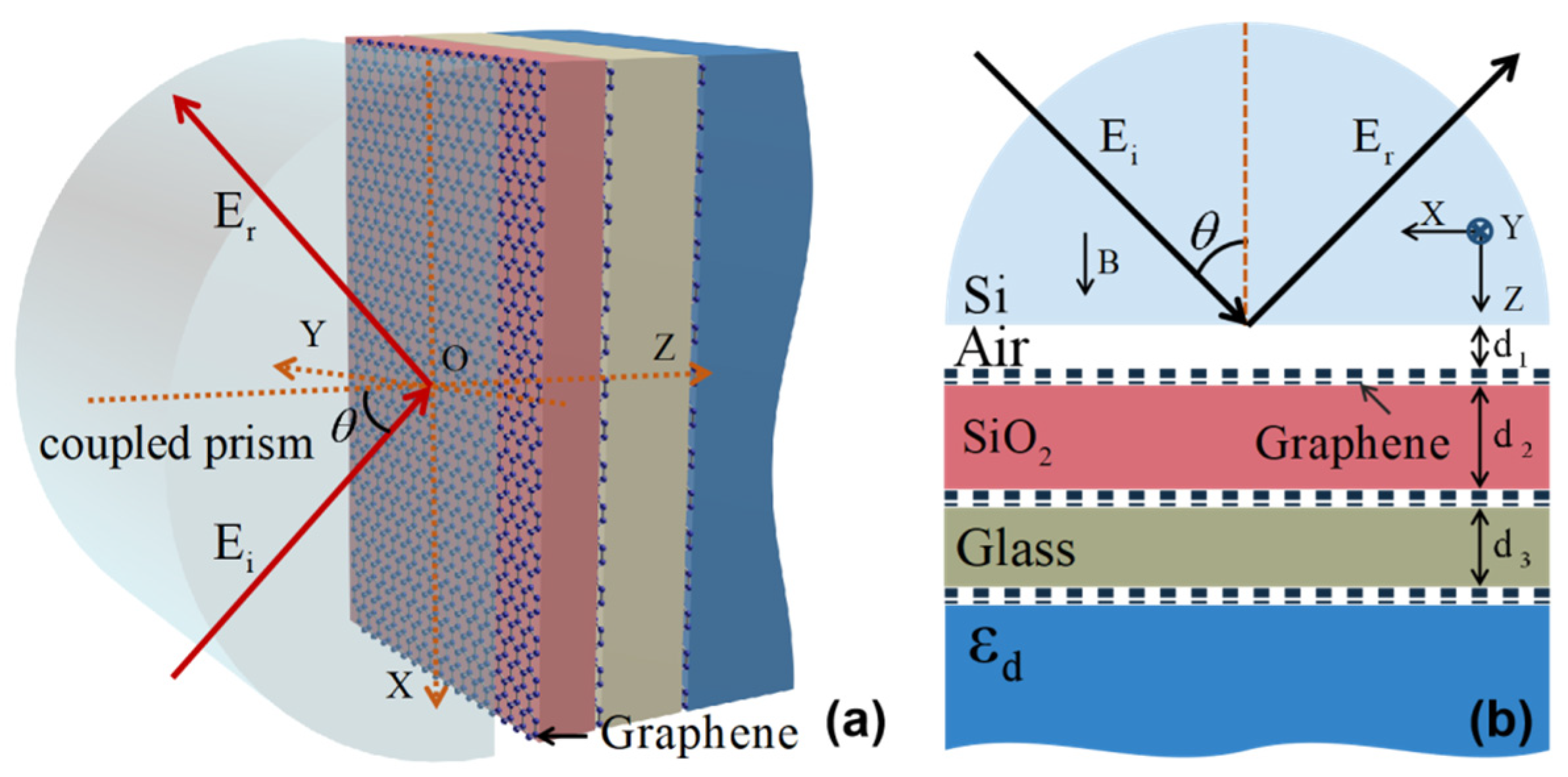
We consider an Otto multilayer structure based on a coupling prism, as shown in Figure 1. There are three layers of graphene in this structure, which are sandwiched between the air layer, the layer, the glass layer and the substrate. Because this paper mainly discusses the variation in the GH shift with the angle at a fixed frequency, there is no need to pay special attention to the material dispersion of each medium. In addition, although the absorption and loss of the medium have a certain impact on the calculation results, considering that this is a purely theoretical work, in order to simplify the model, we also ignored the influence of the absorption and loss of the medium in subsequent calculations. This is also a very common practice in many works. Hence, we set the corresponding dielectric constants of these dielectrics as , , and . Here, we set the thickness of air layer, silica layer and glass layer as . It should be pointed out that this configuration uses a coupling prism structure containing multiple layers of graphene. This is significantly different from the structure in reference [32]. Each graphene layer will have a corresponding SPPs mode excitation under the appropriate structure parameter and material parameter settings, which provides a relatively rich selection for seeking enhanced GH parameters. This structure has more advantages than using single-layer graphene to excite SPPs. We assume the electromagnetic wave is incident as TM polarization and the incident angle is . Furthermore, we also assume that the external magnetic field B is perpendicular to the graphene layer and in the z direction. It is worth mentioning that the strain in two-dimensional nanomaterials can modify their atomic structure; lattice vibration; thermal conductivity; electronic and optical performance; electrical and device performance; and chemical activities. For example, the lattice mismatch between the layers can induce some strain on graphene sheets [33]. This can also significantly change the optical properties of graphene and apply it to GH-related research [34]. In order to simplify the model, the influence of strain will not be considered here for the time being. Based on this, when a uniform static magnetic field is applied perpendicular to the graphene layer, the graphene anisotropic conductivity can be expressed as a tensor of which can be written as:

Figure 1.
Schematic diagram of multilayer structure which can be used for the excitation of SPPs. (a) is the visual view; (b) is the side view. The electromagnetic wave is incident at TM polarization. The external magnetic field along the z-axis direction.
For the doping levels and field strengths in some cases, the distance between Landau levels at Fermi energy is much smaller than at Fermi energy where the graphene can be treated classically. Therefore, when considering the quantum response of graphene under these conditions, the matrix elements of anisotropic conductivity can be expressed as [29,35]:
We use the classic transfer matrix method to calculate the reflectance of the entire structure. The boundary conditions are particularly important in this method. On the one hand, it is the key to determining the transmission matrix D; on the other hand, as an ultra-thin two-dimensional material, graphene’s conductivity characteristics are also reflected in the boundary conditions. Based on the boundary conditions, the transmission matrix D at the interface, between two media containing graphene, can be expressed as follows:
where the boundary conditions meet , and the transmission matrix is expressed as:
Next, we first consider the case where the TM polarization (p polarization) wave is incident on the structure shown in Figure 1. Under the action of an external magnetic field along the z direction, no matter whether the graphene layer is incidented by a TM polarization wave or a TE polarization (s polarization) wave, both the reflected wave and the transmitted wave will have both TM and TE polarization waves. Therefore, both reflected and transmitted waves include TM and TE polarization waves. The reflected coefficient , , can be obtained as follows [37]:
Once these coefficients are worked out, we can obtain the corresponding reflectance , , as follows:
where and are the z and x components of the wave vector in the coupling prism and are related to each other as . The corresponding reflected phase can also be calculated from the reflected coefficient.
When the TM polarization wave is incident on the structure, the GH shift on the entire structure interface can be calculated by the following calculation formula [38]:
where spatial and angular shifts are represented by and , respectively. Among them, stands for Rayleigh length, and is the wave vector in vacuum. represents the beam waist, and other parameters are , , and , . Combining expressions (6)–(13), it is not difficult to see that these parameters are functions that vary with angle. In fact, both spatial shift and angular shift have specific physical meanings. Spatial shift refers to the displacement of the reflected beam in the x-axis direction. Angular shift refers to the deviation angle of the reflected beam from the direction of the reflection angle equal to the incident angle.
3. Results and Discussion
In this section, we will discuss the effect of an external magnetic field on the GH shift of the entire structure. Because the
anisotropic conductivity of graphene can be reflected as a function of the
external magnetic field only when the quantum response of graphene is
considered, we plot the anisotropic conductivity of graphene under different
magnetic fields, as shown in Figure 2.
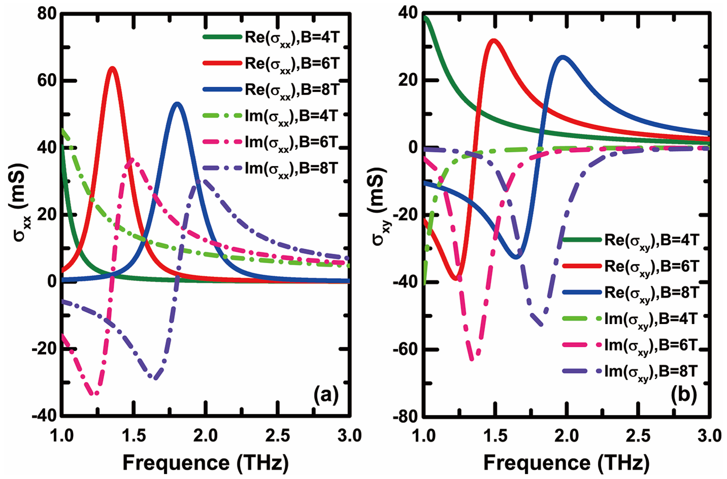
For the convenience of calculation and comparison, we adopt parameters
consistent with those in reference [36]. Here,
we set the excitonic gap as , the chemical
potential as , the scattering rate as and the temperature as . It is easy to see from Figure 2 that the conductivity of graphene depends on the external magnetic field and frequency significantly. The diagonal and off-diagonal elements of graphene conductivity exhibit different curve trends. This is significantly different from the conductivity of graphene in non-magnetic field environments (under the random-phase approximation, the graphene surface conductivity in the terahertz band can be approximately expressed as ). This is also the root cause why the GH shift of the entire structure can be dynamically controlled by an external magnetic field. It is seen that when the weak magnetic field or even the external magnetic field approaches zero, the anisotropic conductivity of graphene will converge with the linear conductivity. In addition, Figure 2 clearly shows that the external magnetic field has a very significant impact on the real and imaginary parts of conductivity. Taking as an example, the increase in external magnetic field causes both the real and imaginary parts of to move towards the high-frequency direction simultaneously. The above characteristics clearly show the possibility of dynamic manipulation of the anisotropic conductivity of graphene through the external non-contact magnetic field. This also creates positive conditions for dynamic manipulation of the GH shift of the entire structure through a magnetic field.

Figure 2.
Real and imaginary parts of (a) and (b) as a function of frequency for different external magnetic fields.
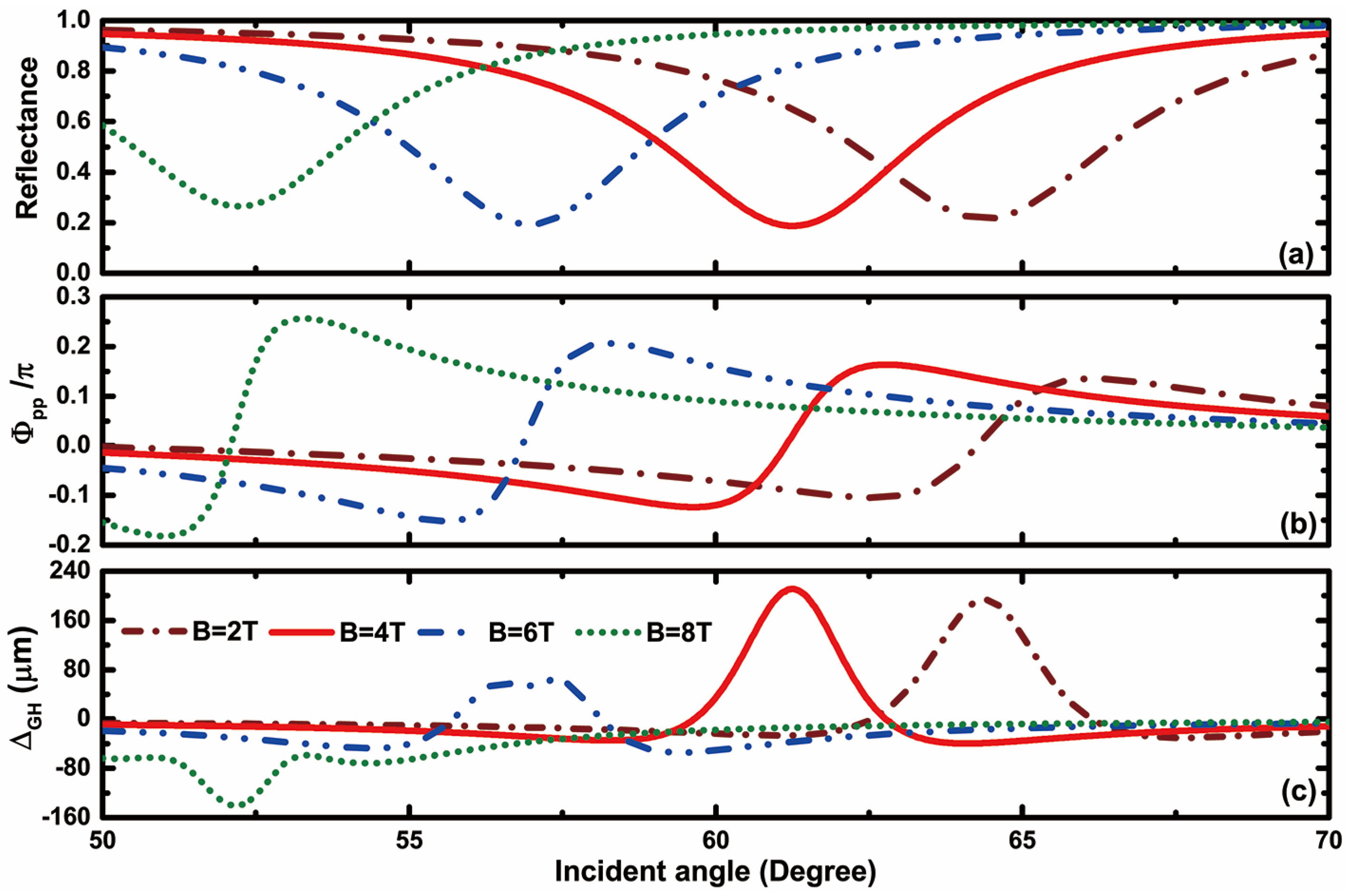
Next, we will focus on discussing the GH shift characteristics of the entire structure under an external magnetic field environment. We know that when considering the anisotropic conductivity of graphene and adopting the new 4 × 4 transfer matrix method, even TM polarization incidence will also include TE polarization and TM polarization reflected beams. This makes the reflected GH shift exhibit diverse characteristics. In order to highlight the focus and simplify the discussion, we will now focus on the case of the TM polarization reflected beam generated during TM polarization incidence. Although the GH shifts can be divided into spatial and angular shifts, without loss of generality, we mainly discuss the spatial shift in this paper. In addition, for the convenience of comparison, we have also arranged the reflectance, reflected phase and reflected GH shift of the entire structure in a column for display, as shown in Figure 3. On the one hand, the whole multilayer structure uses the Otto configuration to excite SPPs, which makes the GH shift at the resonance angle of SPPs significantly enhanced. This is because, according to the calculation formula of the GH shift, the enhanced GH shift is often caused by sharp changes in phase with angle. Usually, the excitation of SPPs is accompanied by a sharp change in the reflected phase near the resonance angle, which creates a pathway for achieving an enhanced GH shift. This has been elaborated on in detail in our previous work [39]. Taking as an example, the excitation of SPPs in the prism coupling structure results in a very obvious reflected dip near 64.7° for the entire reflectance, as shown in Figure 3a. The appearance of this reflected peak is often accompanied by a significant change in the reflected phase. From Figure 3b, it can be seen that the originally smooth reflected phase undergoes a disturbance and drastic change in the angle synchronization generated by the reflected peak due to the excitation of SPPs. This disturbance caused a significant monotonic change in the reflected phase. The reflected phase shows a trend of decreasing firstly, then increasing and then decreasing near the resonance angle, especially in the monotonically increasing region corresponding to the reflected peak, which exhibits a large slope. Combined with expression (14), it is not difficult to find that this is the theoretical root of the enhanced GH shift. The spatial GH shift shown in Figure 3c perfectly illustrates this conclusion. The excitation of SPPs did indeed result in an enhanced GH shift near the resonance angle. On the other hand, the changes in the external magnetic field have a very significant control effect on the GH shift of the whole structure.

Figure 3.
The dependence of the reflectance (a), reflected phase (b) and spatial GH shift (c) on the incident angle at the different external magnetic fields.
From Figure 3, it can be seen that the increase in the external magnetic field causes the resonance angle of SPPs to shift towards a lower angle. The reflected phase also reflects similar trends. However, the spatial GH shift exhibits different characteristics. The increase in the magnetic field not only adjusts the amplitude of the spatial GH shift at the resonance angle but also enables the symbol of to jump between positive and negative. Figure 3c shows that when the magnetic field intensity is reached, can be obtained, and there is a trend of further enhancement of the value with the increase in magnetic field intensity. However, as the magnetic field further increases, the spatial GH shift reaches its maximum value of at and gradually decreases to 0, followed by a reverse increase to around . It is not difficult to see that the external magnetic field achieves dynamic manipulation of the spatial GH shift excited by SPPs, which is not only reflected in amplitude but also in the spatial GH shift sign. This provides a very meaningful way to achieve flexible and dynamically controllable GH shift devices. However, it can also be seen that the complexity of expressions makes it difficult to express an intuitive analytical expression relationship between the degree of positive or negative GH enhancement and the magnitudes of the magnetic field. The influence of the magnetic field on the GH shift has a certain degree of indirectness. The magnitude of the magnetic field plays a more regulatory role in the excitation angle position of SPPs. In other words, we can achieve an enhanced GH shift under smaller magnitudes of the magnetic field by optimizing structural and material parameters. This is very important for achieving flexible control of the GH shift using lower magnitudes of the magnetic field in practical experiments.
In order to further investigate the influence and variation pattern of the external magnetic field on the resonance angle and spatial GH shift of SPPs, we supplemented and plotted the graph of changing with the incident angle and external magnetic field under TM polarization based on Figure 3, as shown in Figure 4. On this basis, we also added the dispersion curve corresponding to the structure shown in Figure 1. Figure 4 shows more clearly the evolution of the spatial GH shift under different magnetic fields and incident angles. Overall, the positive or negative peak of the spatial GH shift matches the position of the resonance angle of SPPs. This results in a “colored strip” appearing in Figure 4. The trend of this “colored strip” with the magnetic field and incident angle is essentially consistent with the dispersion curve of SPPs (the black dashed line in Figure 4). The “colored strip” presents a certain width, and the spatial GH shift in the center part tends to be significantly darker than the spatial GH shift in the edge part. This is because the excitation of SPPs causes the reflected phase to exhibit different trends near the resonance angle. Specifically, on both sides of the resonance angle, the reflected phase shows a decreasing trend as the angle increases. According to the calculation formula for the GH shift, this trend results in negative values of the GH shift on both sides of the resonance angle. However, near the resonance angle, the reflected phase shows a trend of increasing with the increase in the angle. According to the calculation formula for the GH shift, this trend results in a positive value of the GH shift near the resonance angle. This phenomenon is consistent with the phase curve shown in Figure 3b. This is also the reason for the appearance of the “colored strip”. In addition, there is a clear “transition zone” near and at an incident angle of 56° for this “colored strip”. This “transition zone” indicates that under the influence of an external magnetic field, the spatial GH shift begins to exhibit a sign transformation. Furthermore, from Figure 4, we also found that the entire plot presents almost a single color in the area outside the “colored zone”, which means that the spatial GH shift of the entire structure is almost zero without the excitation of SPPs. From this, it can be seen very intuitively that the excitation of SPPs enhances the spatial GH shift significantly. By clearly demonstrating the influence of the external magnetic field and incident angle on the spatial GH shift , it can provide a very intuitive and meaningful reference for the displacement parameters of the entire structure and even corresponding devices.
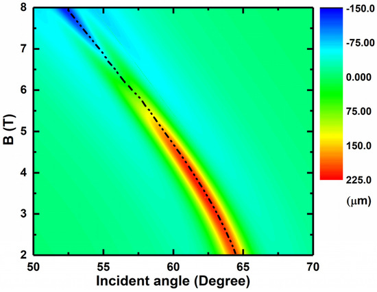
Figure 4.
Dependence of the reflected spatial GH shift on the magnetic field and the incident angle.
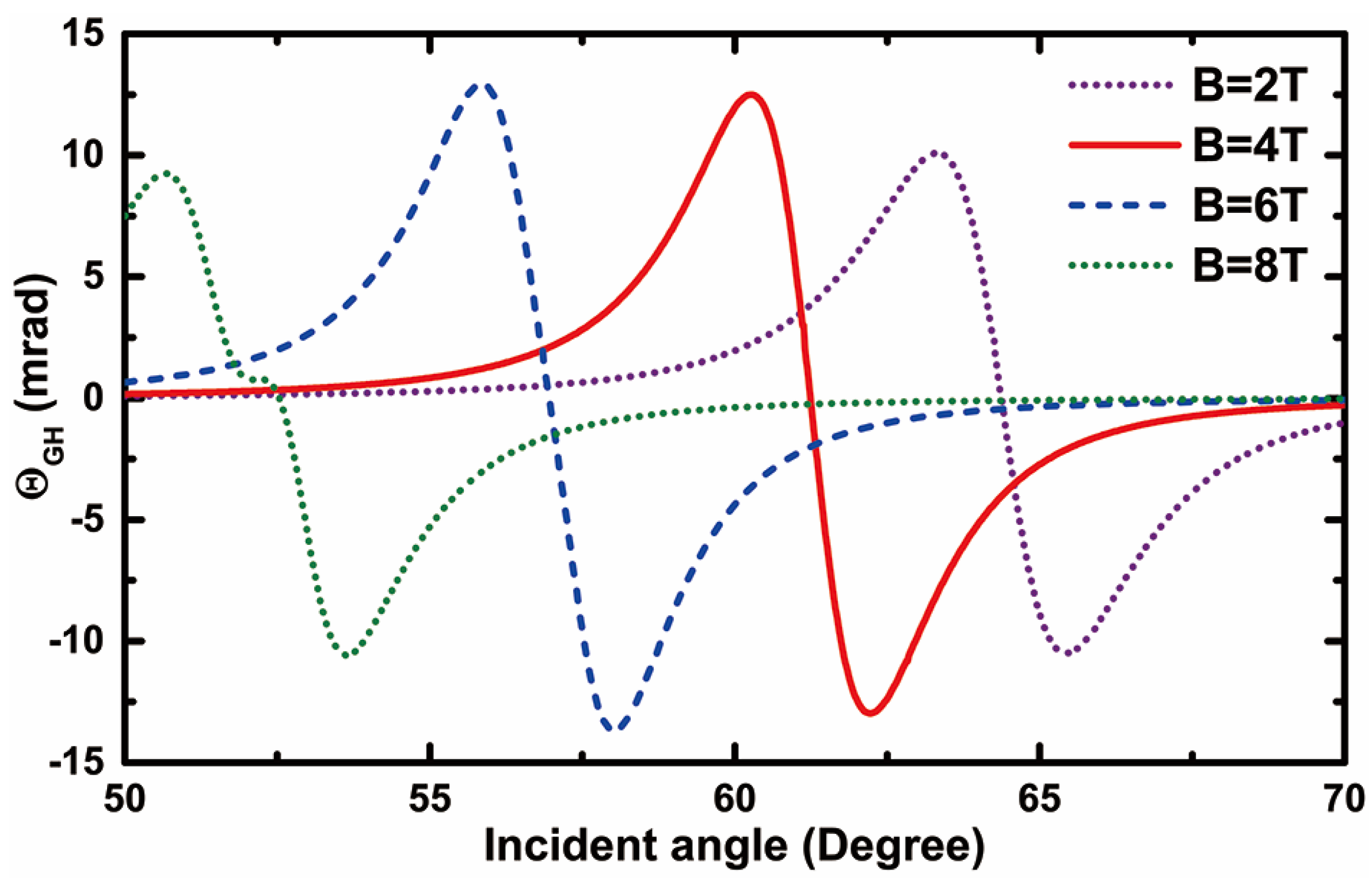
As mentioned earlier, when considering the anisotropy of graphene and adopting the new 4 × 4 transfer matrix method, the GH shift presents not only a spatial GH shift but also an angular shift. Next, we will further discuss the angular GH shift of the structure. Based on expression (15), we plotted the variation curve of the angular GH shift with the incident angle under different magnetic field conditions, as shown in Figure 5. Unlike the enhanced characteristic of the spatial GH shift at the resonance angle, the angular GH shift exhibits a curve characteristic similar to “resonance” near the resonance angle. This characteristic causes the sign of the angular GH shift to jump between positive and negative near the resonance angle. For example, when the magnetic field intensity is , it can be seen that exhibits a positive angular GH shift peak () and a negative angular GH shift peak (), which are exactly on the left and right sides of the resonance angle of . In addition, the external magnetic field can also flexibly and significantly manipulate the angular GH shift . As the external magnetic field gradually increases from , the shift peak of the positive and negative angular GH also matches the resonance angle and moves towards a lower angle. On this basis, the magnitude of the angular GH shift peak will also increase or decrease to varying degrees. As the magnetic field gradually increases from to , the peak shift of the positive and negative angular GH shifts shows a gradually increasing trend. However, as the magnetic field continues to increase from to , the peak shift of the positive and negative angular GH shifts shows a shrinking state, and the slope at the resonance angle also shows a gentle trend. The angular GH shift exhibits a diverse regulation pattern accompanied by an external magnetic field, both in terms of intensity and symbol, which also provides a diverse means for designing shift devices with specific requirements. On the basis of the above discussion, we also compared our scheme with some typical schemes in the references, as shown in Table 1. Through comparison, it is not difficult to see that although this scheme is not the strongest in enhancing GH shift, it is also relatively good. However, in terms of flexibility in tunability, our scheme has obvious advantages.

Figure 5.
The dependence of the angular GH shift on the incident angle at the different external magnetic fields.

Table 1.
Comparison of some typical spatial GH shift methods.
4. Conclusions
In summary, we realized an enhanced GH shift by exciting SPPs based on the Otto structure embedded in anisotropic graphene. This enhanced GH shift is due to the huge phase change caused by the excitation of SPPs. Moreover, the external magnetic field can flexibly control the conductivity of graphene, thus realizing the dynamic and flexible manipulation of the GH shift in value and the positive and negative sign. By setting appropriate magnetic field and structural parameters, we can obtain GH values from −140 microns to 220 microns in the terahertz band. This solution provides a new approach for achieving enhanced and dynamically adjustable GH displacement. Due to the flexible dynamic control method of this scheme, we believe that it will help to find potential applications in high-sensitivity optical sensing, optical detection and other lateral displacement-related devices.
Author Contributions
Conceptualization, X.Z.; Writing—original draft, Y.Y.; Supervision, L.J. All authors have read and agreed to the published version of the manuscript.
Funding
This work is partially supported by the National Natural Science Foundation of China (No. 62375084), the Scientific research project of Zhejiang Provincial Department of Education (Grant No. Y202250547), the Natural Science Foundation of Hunan Province (Grant No. 2022JJ30394), the Scientific Research Fund of Hunan Provincial Education Department (Grant No. 21B0048), the scientific research project of Wenzhou University of Technology (Grant No. ky202205), the Wenzhou major science and technology innovation project (No. 2023ZW0045) and Wenzhou scientific research project (No. 2023Y2159).
Institutional Review Board Statement
Not applicable.
Informed Consent Statement
Not applicable.
Data Availability Statement
Data available on request due to restrictions e.g., privacy or ethical.
Conflicts of Interest
The authors declare no conflict of interest.
References
- Snyder, A.W.; Love, J.D. Goos-Hänchen shift. Appl. Opt. 1976, 15, 236–238. [Google Scholar] [CrossRef] [PubMed]
- Sakata, T.; Togo, H.; Shimokawa, F. Reflection-type 2 × 2 optical waveguide switch using the Goos-Hänchen shift effect. Appl. Phys. Lett. 2000, 76, 2841–2843. [Google Scholar] [CrossRef]
- Yu, T.Y.; Li, H.G.; Cao, Z.Q.; Wang, Y.; Shen, Q.S.; He, Y. Oscillating wave displacement sensor using the enhanced Goos-Hänchen effect in a symmetrical metal-cladding optical waveguide. Opt. Lett. 2008, 33, 1001–1003. [Google Scholar] [CrossRef] [PubMed]
- Kar, A.; Goswami, N.; Saha, A. Analysis of high-resolution electro-optical beam steering by long-range surface plasmon resonance using a ZnSe prism. Appl. Opt. 2017, 56, 9656–9662. [Google Scholar] [CrossRef]
- Zhou, X.; Liu, S.; Ding, Y.; Min, L.; Luo, Z. Precise controlling of positive and negative Goos-Hänchen shifts in graphene. Carbon 2019, 149, 604–608. [Google Scholar] [CrossRef]
- Li, K.; Cheng, F. Effects of strain on Goos-Hänchen shifts of monolayer phosphorene. Phys. E Low-Dimens. Syst. Nanostructures 2018, 97, 335–339. [Google Scholar] [CrossRef]
- Qing, D.K.; Chen, G. Goos-Hänchen shifts at the interfaces between left- and right-handed media. Opt. Lett. 2004, 29, 872–874. [Google Scholar] [CrossRef]
- Dadoenkova, Y.S.; Dadoenkova, N.N.; Kłos, J.W.; Krawczyk, M.; Lyubchanskii, I.L. Goos-Hänchen effect in light transmission through biperiodic photonic-magnonic crystals. Phys. Rev. A 2017, 96, 043804. [Google Scholar] [CrossRef]
- Zhen, W.M.; Deng, D.M. Goos-Hänchen and Imbert-Fedorov shifts in temporally dispersive attenuative materials. J. Phys. D Appl. Phys. 2020, 53, 255104. [Google Scholar] [CrossRef]
- Felbacq, D.; Moreau, A.; Smaâli, R. Goos-Hänchen effect in the gaps of photonic crystals. Opt. Lett. 2003, 28, 1633–1635. [Google Scholar] [CrossRef]
- Soboleva, I.V.; Moskalenko, V.V.; Fedyanin, A.A. Giant Goos-Hänchen effect and Fano resonance at photonic crystal surfaces. Phys. Rev. Lett. 2012, 108, 123901. [Google Scholar] [CrossRef]
- You, Q.; Zhu, J.Q.; Guo, J.; Wu, L.M.; Dai, X.Y.; Xiang, Y.J. Giant Goos–H¨anchen shifts of waveguide coupled long-range surface plasmon resonance mode. Chin. Phys. B 2018, 27, 087302. [Google Scholar] [CrossRef]
- Huerkamp, F.; Leskova, T.A.; Maradudin, A.A.; Baumeier, B. The Goos-Hänchen effect for surface plasmon polaritons. Opt. Express 2011, 19, 15483–15489. [Google Scholar] [CrossRef] [PubMed]
- Yang, R.; Zhu, W.K.; Li, J.J. Giant positive and negative Goos-Hänchen shift on dielectric gratings caused by guided mode resonance. Opt. Express 2014, 22, 2043–2050. [Google Scholar] [CrossRef]
- Namdar, A.; Shadrivov, I.V.; Kivshar, Y.S. Excitation of backward Tamm states at an interface between a periodic photonic crystal and a left-handed metamaterial. Phys. Rev. A 2007, 75, 053812. [Google Scholar] [CrossRef]
- Wu, W.J.; Zhang, W.S.; Chen, S.Z.; Ling, X.H.; Shu, W.X.; Luo, H.L.; Wen, S.C.; Yin, X.B. Transitional Goos-Hänchen effect due to the topological phase transitions. Opt. Express 2018, 26, 23705–23713. [Google Scholar] [CrossRef] [PubMed]
- Cao, Y.Y.; Fu, Y.Y.; Zhou, Q.J.; Xu, Y.D.; Gao, L.; Chen, H.Y. Giant Goos-Hänchen shift induced by bounded states in optical PT-symmetric bilayer structures. Opt. Express 2019, 27, 7857–7867. [Google Scholar] [CrossRef]
- Pati, A.; Gordon, R. Plasmonic slot waveguide propagation analysis. Plasmonics 2023, 18, 551–560. [Google Scholar] [CrossRef]
- Mohammadi, M.; Soroosh, M.; Farmani, A.; Ajabi, S. Engineered FWHM enhancement in plasmonic nanoresonators for multiplexer/demultiplexer in visible and NIR range. Optik 2019, 274, 170583. [Google Scholar] [CrossRef]
- Salehnezhad, Z.; Soroosh, M.; Farmani, A. Design and numerical simulation of a sensitive plasmonic-based nanosensor utilizing MoS2 monolayer and graphene. Diam. Relat. Mater. 2023, 131, 109594. [Google Scholar] [CrossRef]
- Mikhailov, S.A.; Ziegler, K. New Electromagnetic Mode in Graphene. Phys. Rev. Lett. 2006, 99, 016803. [Google Scholar] [CrossRef] [PubMed]
- Li, Z.Q.; Henriksen, E.A.; Jiang, Z.; Hao, Z.; Martin, M.C.; Kim, P.; Stormer, H.L.; Basov, D.N. Dirac charge dynamics in graphene by infrared spectroscopy. Nat. Phys. 2008, 4, 532–535. [Google Scholar] [CrossRef]
- Bonaccorso, F.; Sun, Z.; Hasan, T.; Ferrari, A.C. Graphene photonics and optoelectronics. Nat. Photonics 2010, 4, 611–622. [Google Scholar] [CrossRef]
- You, Q.; Shan, Y.; Gan, S.; Zhao, Y.; Dai, X.Y.; Xiang, Y.J. Giant and controllable Goos-Hänchen shifts based on surface plasmon resonance with graphene-MoS2 heterostructure. Opt. Mater. Express 2018, 8, 3036–3048. [Google Scholar] [CrossRef]
- Mekkaoui, M.; Kinani, R.E.; Jellal, A. Goos-Hänchen shifts in graphene-based linear barrier. Mater.Res. Express 2019, 6, 085013. [Google Scholar] [CrossRef]
- Li, T.W.; Da, H.X.; Du, X.D.; He, J.J.; Yan, X.H. Giant enhancement of Goos-Hänchen shift in graphene-based dielectric grating. J. Phys. D Appl. Phys. 2020, 53, 225103. [Google Scholar] [CrossRef]
- Cheng, M.; Fu, P.; Chen, X.Y.; Zeng, X.H.; Feng, S.Y.; Chen, R. Giant and tunable Goos-Hänchen shifts for attenuated total reflection structure containing graphene. J. Opt. Soc. Am. B 2014, 31, 2325–2329. [Google Scholar] [CrossRef]
- Zeng, X.D.; Al-Amri, M.; Zubairy, M.S. Tunable Goos-Hänchen shift from graphene ribbon array. Opt. Express 2017, 25, 23579–23588. [Google Scholar] [CrossRef]
- Gusynin, V.P.; Sharapov, S.G.; Carbotte, J.P. Magneto-optical conductivity in graphene. J. Phys. Condens. Matter 2007, 19, 026222. [Google Scholar] [CrossRef]
- Jahani, D.; Akhavan, O.; Alidoust Ghatar, A. Magneto-tunable terahertz absorption in single-layer graphene: A general approach. Phys. E 2023, 151, 115728. [Google Scholar] [CrossRef]
- Cheng, R.; Zhou, Y.; Liu, H.; Liu, J.; Sun, G.; Zhou, X.; Shen, H.; Wang, Q.; Zha, Y. Tunable graphene-based terahertz absorber via an external magnetic field. Opt. Mater. Express 2020, 10, 501–512. [Google Scholar] [CrossRef]
- Jahani, D.; Akhavan, O.; Alidoust Ghatar, A. Optical quantum Hall Goos–Hänchen effect in graphene. Phys. Lett. A 2023, 465, 128700. [Google Scholar] [CrossRef]
- Deng, S.; Sumant, A.V.; Berry, V. Strain engineering in two-dimensional nanomaterials beyond graphene. Nano Today 2018, 22, 14–35. [Google Scholar] [CrossRef]
- Jahani, D.; Akhavan, O.; Hayat, A.; Shah, M. Optical Goos–Hänchen effect in uniaxially strained graphene. J. Opt. Soc. Am. A 2023, 40, 21–26. [Google Scholar] [CrossRef] [PubMed]
- Da, H.; Qiu, C.W. Graphene-based photonic crystal to steer giant Faraday rotation. Appl. Phys. Lett. 2012, 100, 241106. [Google Scholar] [CrossRef]
- Ardakani, A.G.; Ghasemi, Z.; Golshan, M.M. A new transfer matrix for investigation of surface plasmon modes in multilayer structures containing anisotropic graphene layers. Eur. Phys. J. Plus 2017, 132, 206. [Google Scholar] [CrossRef]
- Yin, X.B.; Hesselink, L.; Liu, Z.W.; Fang, N.; Zhang, X. Large positive and negative lateral optical beamdisplacements due to surface plasmon resonance. Appl. Phys. Lett. 2004, 85, 372–374. [Google Scholar] [CrossRef]
- Ye, G.Z.; Zhang, W.S.; Wu, W.J.; Chen, S.Z.; Shu, W.X.; Luo, H.L.; Wen, S.C. Goos-Hänchen and Imbert-Fedorov effects in Weyl semimetals. Phys. Rev. A 2019, 99, 023807. [Google Scholar] [CrossRef]
- Zheng, Z.; Lu, F.; Jiang, L.; Jin, X.; Dai, X.; Xiang, Y. Enhanced and controllable Goos-Hänchen shift with graphene surface plasmon in the terahertz regime. Opt. Commun. 2019, 452, 227–232. [Google Scholar] [CrossRef]

Disclaimer/Publisher’s Note: The statements, opinions and data contained in all publications are solely those of the individual author(s) and contributor(s) and not of MDPI and/or the editor(s). MDPI and/or the editor(s) disclaim responsibility for any injury to people or property resulting from any ideas, methods, instructions or products referred to in the content. |
© 2023 by the authors. Licensee MDPI, Basel, Switzerland. This article is an open access article distributed under the terms and conditions of the Creative Commons Attribution (CC BY) license (https://creativecommons.org/licenses/by/4.0/).