Article

PVD Black Coating for Decorative Applications

1
Centro de Física, Campus de Azurém, Universidade do Minho, 4800-053 Guimarães, Portugal
2
KLC, Zona Industrial Casal da Lebre, Estrada dos Guilhermes 143, 2430-021 Marinha Grande, Portugal
3
CEMMPRE, Department of Mechanical Engineering, University of Coimbra, Rua Luís Reis Santos, 3030-788 Coimbra, Portugal
*
Author to whom correspondence should be addressed.
Coatings 2023, 13(11), 1838; https://doi.org/10.3390/coatings13111838
Submission received: 19 September 2023 / Revised: 22 October 2023 / Accepted: 24 October 2023 / Published: 27 October 2023
(This article belongs to the Special Issue Perspective Coatings for Optical Materials Modifications)

Abstract

:
PVD coatings have gained considerable attention as decorative coatings because they combine decorative with protective properties. Within the frame of this work, a black PVD coating based on chromium, carbon and oxygen was developed in a semi-industrial coating machine with four magnetrons and continuous substrate rotation. Based on the optical properties of CrxCyOz, the optical properties of the coating can be used in the design of the coating. EDX measurements point to an average composition of Cr0.35O0.53C0.12 for coatings with the most interesting optical properties. XPS measurements show that the chemical state of the constituting elements changes throughout the coating thickness. CrxCyOz shows a strong columnar growth which may give origin to a rough surface structure. This effect, depending on the coating thickness, allows the deposition of black coatings with a variation of strong specular reflection (“piano black”) and diffuse reflection (“matt”) for a coating thickness variation between 1 and 5 μm. The diffusive reflection increased from almost 2% to 6% for the thicker samples whereby the specular reflection decreased from about 20% to almost 0 of the samples with a thin coating and samples with a coating thickness close to 5 μm. Within the frame of this work, we also determined the functional properties of adherence and surface energy, which show that the coating can be used in demanding applications without an additional protective topcoat.

1. Introduction

In multiple applications a decorative and protective coating is used on metallic or polymeric substrates. Ceramic coatings deposited by Physical Vapor Deposition (PVD) may simultaneously be hard and therefore protective against abrasion, of good adherence and of an attractive color. The most prominent examples may be gold-colored TiN and ZrN coatings, which are used for jewelry, watches and bathroom appliances [1,2,3,4]. Similar applications require decorative and protective black coatings. Other applications of black coatings are pyroelectric conversion [5,6] and photothermal detectors [7,8,9,10]. Common to these applications is the usage of batch coating systems to cover 3D surfaces. The coating solutions in these circumstances are different from the coating of optical multilayered coatings. In spectrally selective coatings, as used for solar thermal systems [11,12,13], the coating systems consist, in these cases, of a multilayered coating, where each layer with very well-defined optical properties is relatively thin with an optical thickness of one quarter or a half wavelength of visible light. Furthermore, those coatings may be deposited in in-line coating machines with very well-defined vacuum conditions.
Within the frame of this work, we pretend to develop a coating which can be deposited in PVD batch coating machines, consisting of layers with various thicknesses and a small variation in vacuum conditions without influencing the optical appearance.
The decorative appearance of a surface is influenced both by its capability to absorb radiation and the surface roughness. Increasing the surface roughness will reduce the reflectance due to multiple reflections and absorption, but also increase the diffuse reflection giving it a matt appearance. Typical solutions to achieve a black matt appearance, such as black chromium [14], black nickel [15], black platinum [16] and black aluminum [17], are mostly obtained with chemical methods and rely on the surface morphology of the coating in combination with some absorption of the coating material itself.
To produce a so-called piano black appearance, the surface must be smooth and optically absorbing. In optics, a black coating has a low reflectance R, which is uniform for all wavelengths in the visible range. To guarantee a good coating adherence, a thin metallic interlayer is usually applied prior to the deposition of the thick ceramic coating both on metallic and polymeric substrates. From an optical point of view, this metallic interlayer functions as a mirror. The optical properties of the decorative layer are the complex refractive index ñc = nc + j kc, with a refractive index nc and an extinction coefficient kc. In general, the nc should be as low as possible to reduce reflections and kc should have an intermediate value (Equation (1)). If kc is <<0.1, the absorption is neglectable and interference effects will dominate reflectivity R, giving origin to its colored appearance. For a semi-infinite coating, kc > 1, kc will contribute significantly to the absolute value of the complex refractive index and increase the reflectivity according to Equation (1) [18] under normal incidence, with ña being the refractive index of the non-absorbing ambient.
R = ñ c ñ a ñ c + ñ a 2 = n c n a 2 + k c 2 n c n a 2 + k c 2
In the literature, numerous black PVD [19] coatings based on TixOyCz, [20,21], AlON [22], DLC [23], Al2O3 (Ti) [24] and Cr2O3 (Cr) [25,26] are mentioned. Those coating solutions are all based on semitransparent coating.
Within the frame of this work, we focus on the deposition and characterization of a black coating-based on chromium, oxygen and carbon CrxCyOz. In a first step, the optical parameters with the goal of lowering the reflectivity were optimized. We also describe how the surface appearance changes from reflective black (piano black) to matt appearance with an increase in coating thickness and coating roughness. In a second step, the physical properties of the coating (adherence, surface energy and chemical resistance) are evaluated.

2. Experimental Conditions

2.1. Coating Deposition

The coatings were deposited in a 4 magnetron semi-industrial Physical Vapor Deposition (PVD) chamber, Teers UDP 650, as described in [27] by unbalanced DC magnetron sputtering. Substrates were attached to a rotating holder. The substrates consisted in stainless steel 304 disks with a thickness of 2 mm, which were polished to a roughness of ra < 10 nm. Together with the steel samples, Si-wafer samples were coated. The coated wafer samples were used during compositional analysis to exclude the influence of the substrate material. All substrates were ultrasonically cleaned in organic solution and ethanol prior to be attached in the vacuum chamber, the chamber was pumped down to a base pressure < 10−5 mbar and then the samples were plasma etched during 20 min. Afterwards a 220 nm thick Cr layer was deposited and subsequently the CrxCyOz layer was deposited employing a chromium and a carbon target and an Ar and oxygen gas flow, as quantified in Table 1. During deposition, a pulsed bias at 250 kHz and an off-time of 1240 nanoseconds, controlling negative bias voltage, was applied to the substrate holder. All samples, but sample C-38 were exposed to the same bias. It should be mentioned that the deposition parameters target and bias voltage and current and chamber pressure were continuously controlled during the deposition period and no changes were observed.
The configuration as described above is used in numerous batch coaters used for decorative coatings deposited by PVD methods. The advantage of the configuration is the deposition of an almost homogenous mixture of different materials. The disadvantage is, even in a single fold rotation, even more in two- or three-fold rotation as employed in larger machines, a variation of the coating deposition conditions. As indicated above, one goal of the work is to develop a coating for which these small variations do not influence the appearance of the coating.

2.2. Coating Characterization

After deposition, the coatings were characterized by measuring the optical reflectance in a Shimadzu spectrophotometer. Specular reflectance was measured in a double beam configuration, comparing the samples reflectance with the reflectance of an Ag-mirror, and diffuse reflectance was measured using an integrating sphere, which eliminates specular reflection by allowing specular reflected light leaving the sphere [28]. The surface color was measured using a Minolta CM-2600d (Minolta Spain, Valencia, Spain) portable spectrophotometer describing the color in L*, a*, b* color space [29]. Coating thickness was measured by ball cratering and Scanning Electron Microscopy (SEM) and coating composition by Energy Dispersive X-ray spectroscopy (EDX). To eliminate the influence of the substrate, the EDX composition was measured for the coatings deposited simultaneously on stainless steel and silicon. This procedure allowed the researchers to discount the influence of the substrate on the coating composition, always admitting a semi-infinite medium. In addition, coating composition and chemical information of the elements close to the surface were evaluated by X-ray Photoelectron Spectroscopy (XPS-ESCALAB 250Xi (Thermo Fisher Scientific, Waltham, MA, USA)). Prior to each XPS analysis, the sample surface was subjected to an Ar-etch, removing about 5 nm.
The scratch testing method was used to evaluate the adhesive behavior of the coatings. Tests were carried out in the CSEM Revetest device. The diamond stylus, with a tip radius of 0.2 mm, was loaded against the coated substrate with a loading rate of 10 N/min [30]. The coating roughness was quantified by Atomic Force Microscopy (AFM) [31]. The chemical properties, like surface energy (based on the subsequent measurement of the dynamic contact angle of water, glycerol and squalene drops on the sample surface measured with OCA 20 instrument from Dataphysics (Dataphysics, Filderstadt, Germany) [32]), and the chemical resistance by artificial soiling with fingerprints and ketchup and subsequent cleaning in a standard dish washing program at 65 °C for 240 min.

2.3. Simulation of Optical Properties

If ña, ño and ñc are the complex refractive indices at wavelength λ of the ambient air, opaque adhesion layer and semitransparent coating (of thickness d) the reflectivity Rsim can be calculated using to Equation (2) [15], as follows:
R s i m λ = e j 2 π n c 2 d λ   ñ o + ñ a ñ a ñ c + ñ o ñ a ñ a + ñ c e j 2 π n c 2 d λ   ñ o ñ a ñ a ñ c + ñ o + ñ a ñ a + ñ c 2
The complex refractive index of chromium (ño) is tabulated in the literature [33], the thickness d was measured, as described above, by ball cratering and the parameters ñc = nc + j kc were obtained by fitting the simulated value of Rsim to the experimentally determined Rexp, as shown in for two samples C-43 and C-48, respectively. Finally, j is used to indicate the imaginary part of the complex numbers. Equations (1) and (2) are valid for specular reflectance.

3. Results

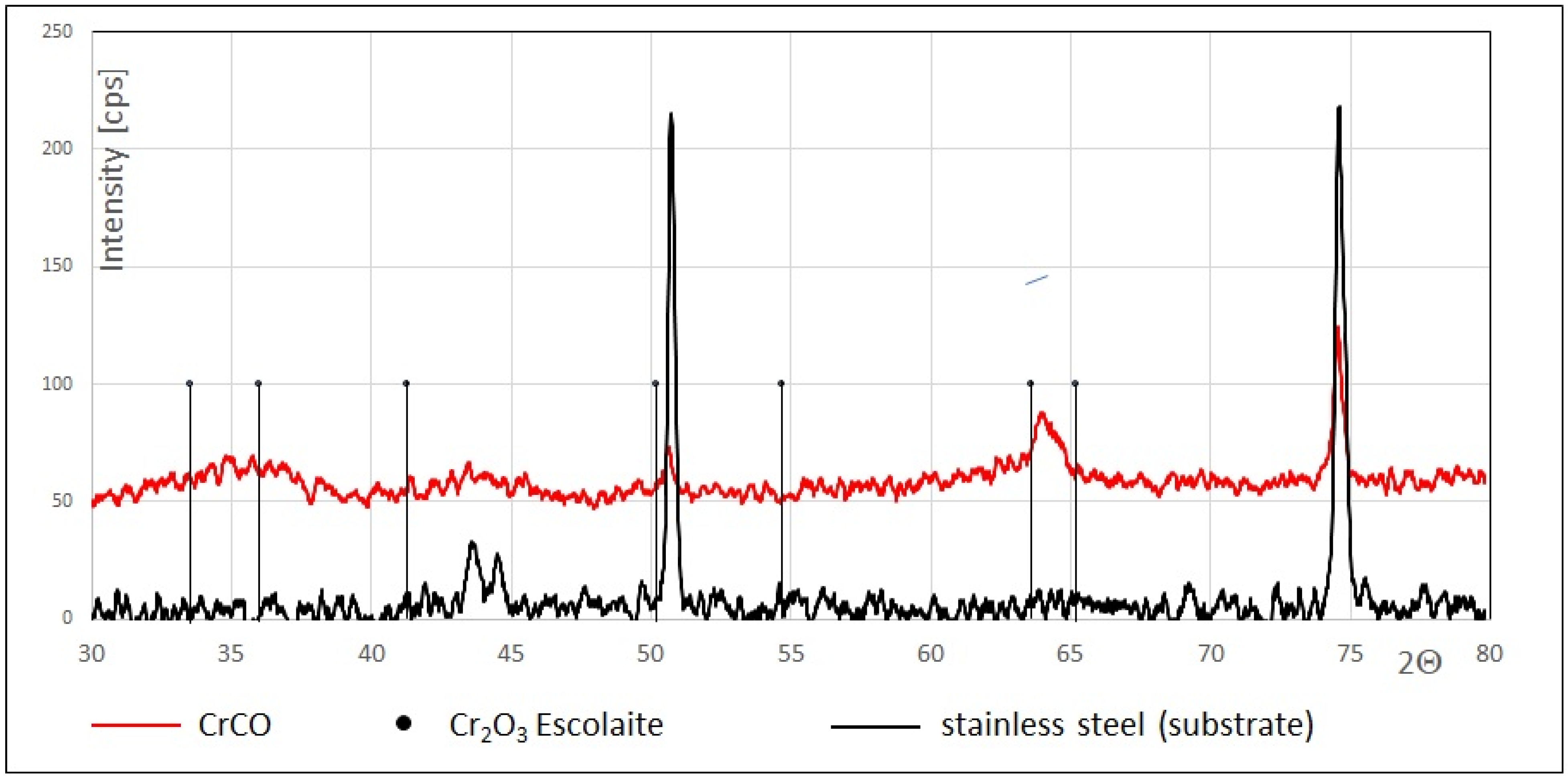
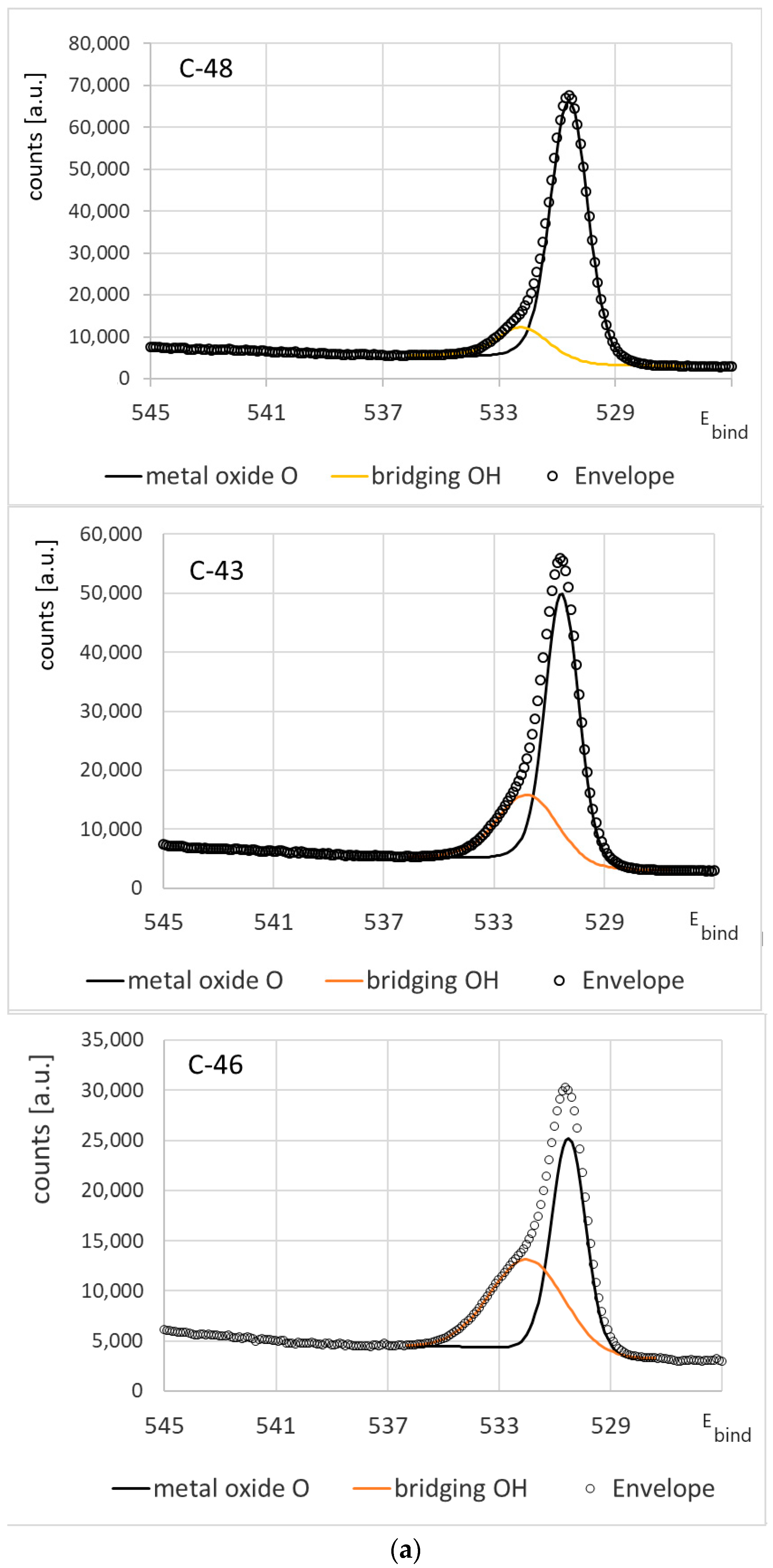
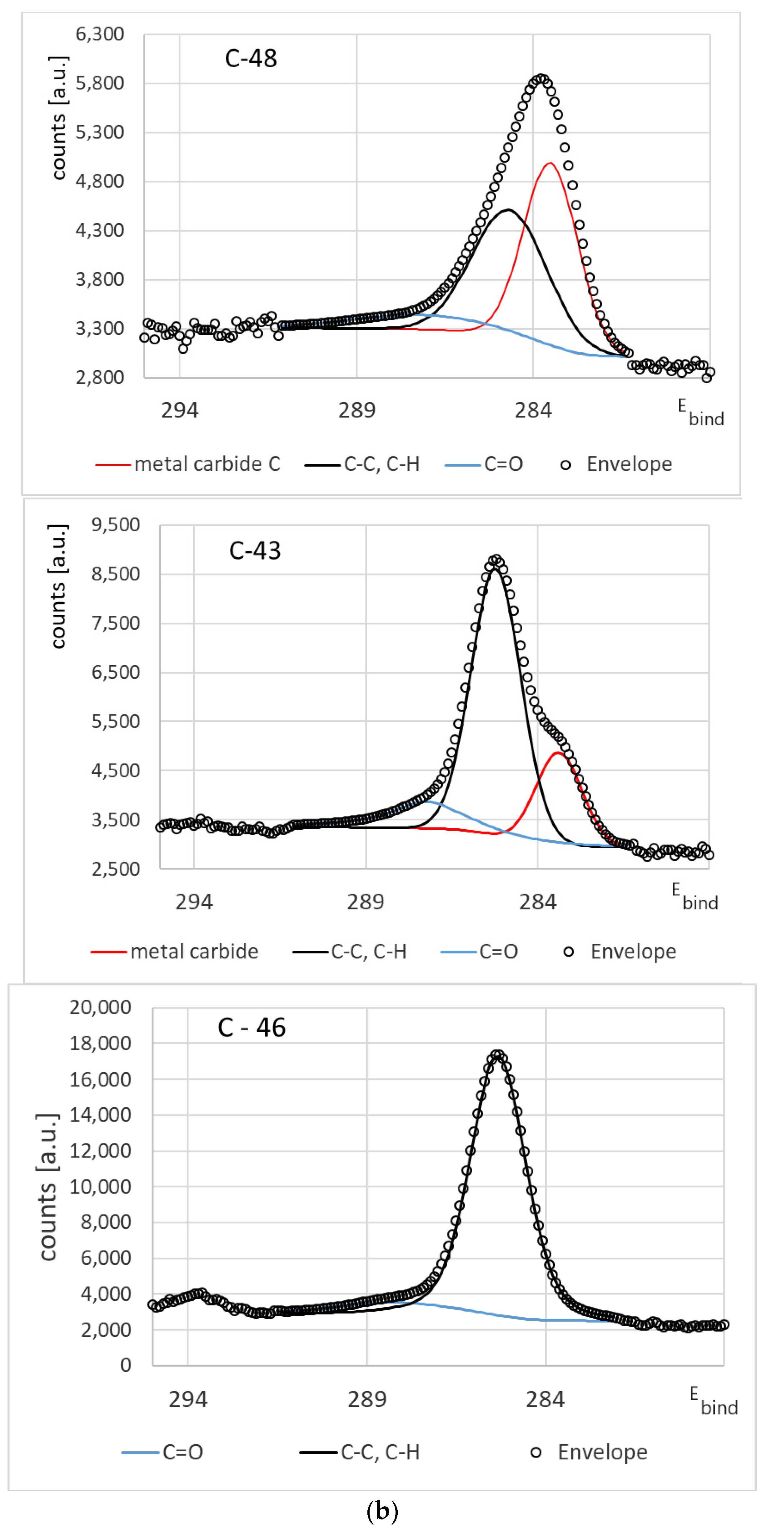
3.1. Chemical Composition

The chemical composition of the coatings is listed in Table 2, and the EDX measurements suggest a composition Cr0.35O0.53C0.12. The ratio between Cr and O is for all samples close to the expected ratio for Cr2O3. Nevertheless, even for the 4.8 mm thick coating, C-46, XRD experiments only reveal traces of crystalline Cr2O3; the coating is mostly X-ray amorphous, as shown in Figure 1. The dots indicate the expected peak position of Cr2O3 (Escolaite) [34]. There might be some broad reflections from the (214) and (300) directions at around 2Θ = 65° of Cr2O3.
XPS analysis was performed on the C-48, C-43 and C-46 samples and shows the compositions are close to the sample surface. For the thin coating in samples C-48 and C-43, the composition is close to the composition measured by EDX. For the thicker coating, there seems to be some carbon accumulation close to the surface and a higher oxygen/metal ratio. The peak deconvolution in Figure 2 gives a closer insight into the binding status of the main elements.
For the thin coating (C-48), the carbon connects mainly to the Cr-metal. With the increasing coating thickness, the carbon is connected to other carbon atoms or to hydrogen atoms. The oxygen binds preferentially to the metal atoms for the thin coatings. For thick coatings, oxygen in the form of O-H increased.

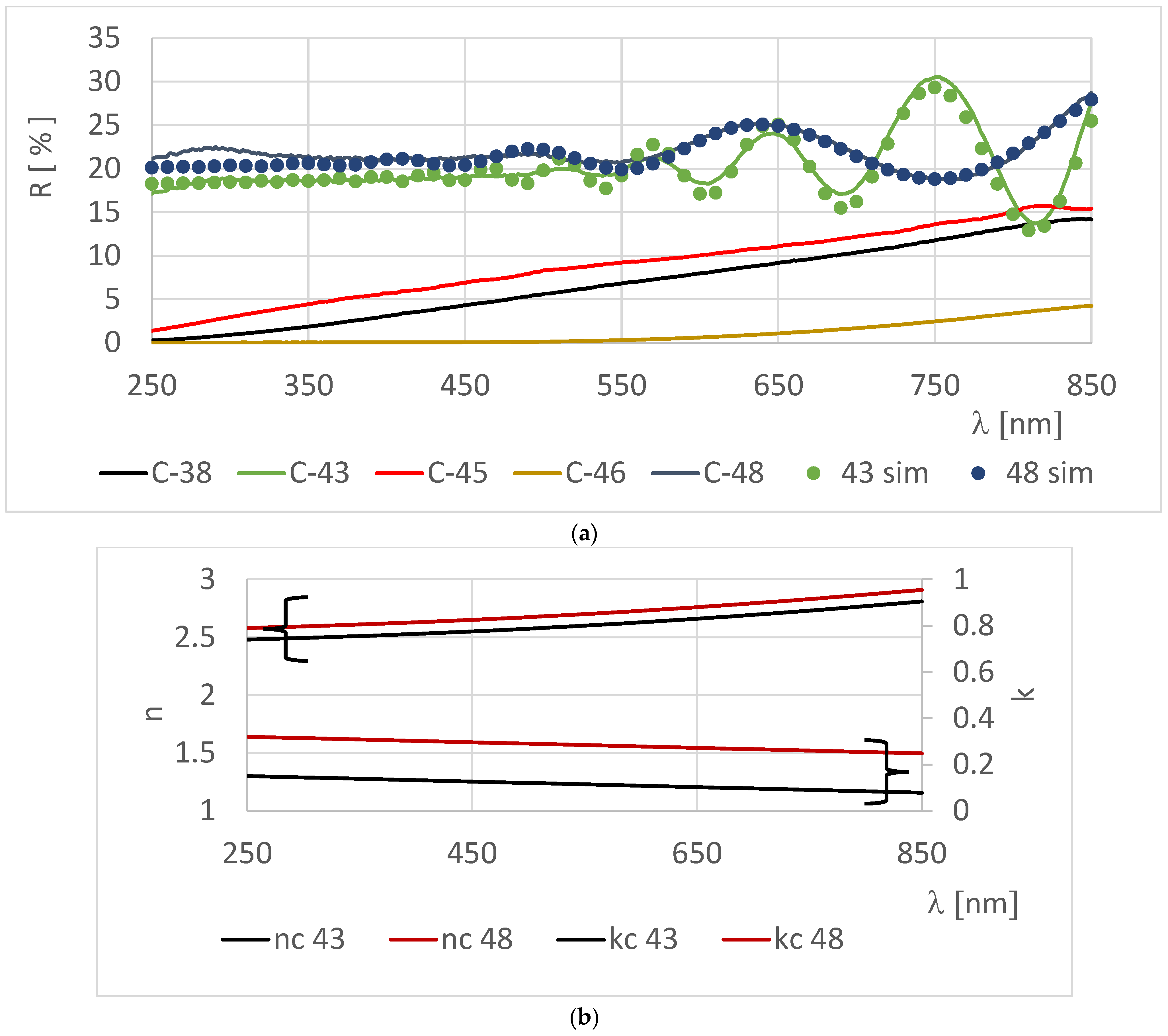
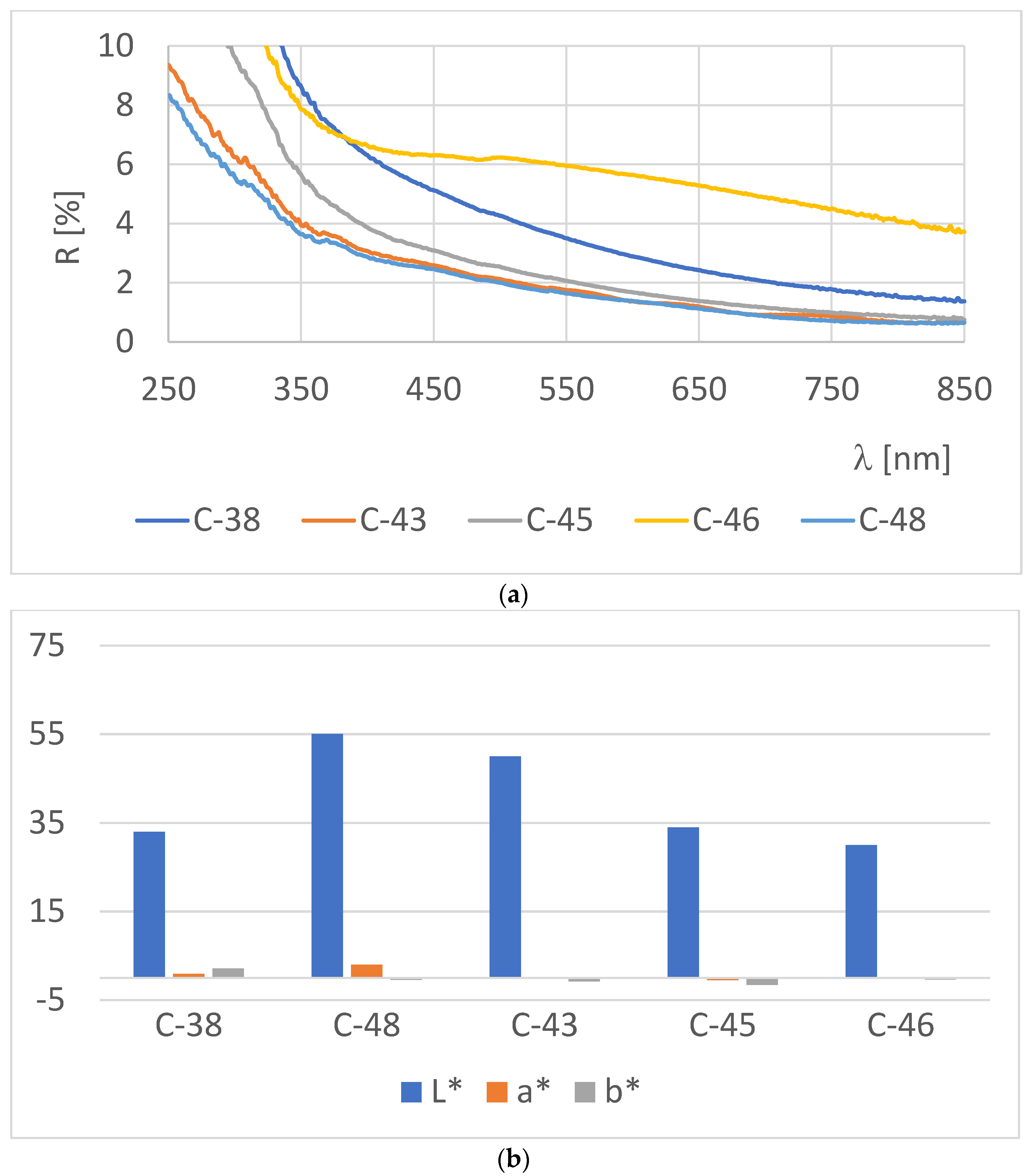
3.2. Optical Properties

Visually, all samples have a black appearance ranging from piano black to matt according to the coating thickness. Figure 3a shows the specular reflectance of all samples. Samples 43 and 48, which are comparatively thin, show a dark reflective surface and the reflectance spectrum suggests an interference pattern. The interference pattern allows a simulation of the reflection curve according to Equation (2) using the thickness values according to Table 2. The simulation was automated in the Excel application using the optical properties of the metallic Cr- reflection layer and the coating thickness as fixed input parameters and obtaining the nc(λ) and kc(λ) of the coating as output. Figure 3b shows the values of nc(λ) and kc(λ) resulting from the simulation. For samples with thicker coatings, the interference effects are attenuated by the absorption throughout the coating thickness, by an increase in diffuse reflection and therefore a reduction in specular reflected light. Samples C-38, C-45 and C-46 do not show the interference patterns.
Samples C-38, C-45 and C-46 were prepared at similar experimental conditions as samples C-48 and C-43, but with an increased deposition time and, therefore, an increased coating thickness. When applying a higher coating thickness in Equation (2), the reflectivity will approach the thickness independent reflectivity of Equation (1). Based on our values of nc and kc, a total reflectivity of about 20% is expected.
Visual examination of the coatings reveals a tendency to become more matt. This can also be verified experimentally by measuring the diffuse reflectance (Figure 4). With increasing thickness, the diffuse reflectance increases. Nevertheless, it is interesting to note, that the total reflectance (diffuse + specular) diminishes with the increasing coating thickness.
The L*a*b* parameters give us comprehension of color by accounting for both the reflectivity spectra of materials and the sensitivity of the human eye. In the present work, the appearance of the Cr0.35O0.53C0.12 coatings was measured in CIELab 1976 color space L*, a*, b*. All coatings, except the thinnest coating, C-46, present a L* value < 50, describing the black appearance. A* and b* are close to zero, indicating that the human eye will not detect color. The Minolta CM-2600d portable spectrophotometer measures simultaneously specular and diffuse reflection and therefore does not distinguish between matt and specular reflective appearance in our analysis.

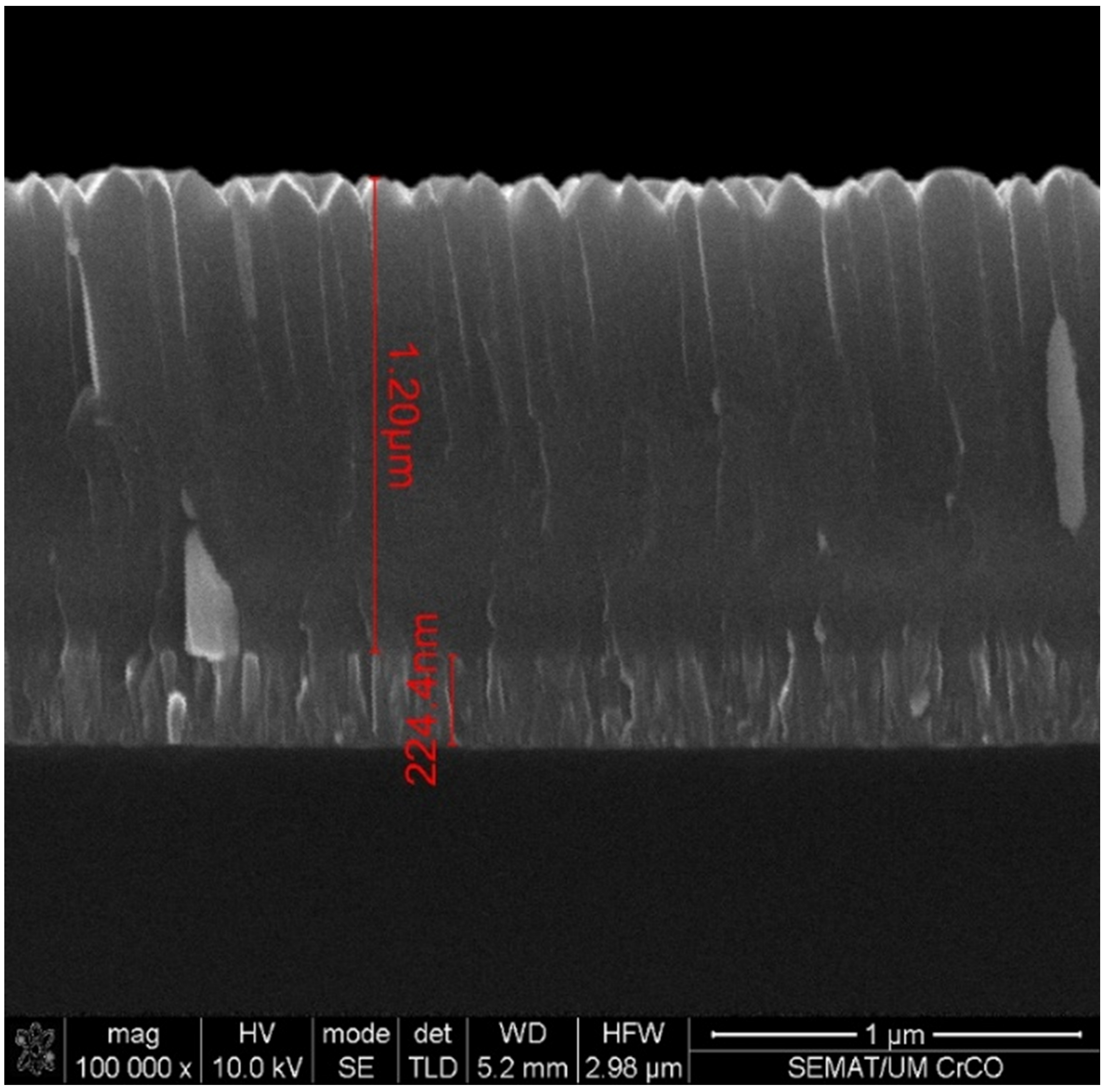
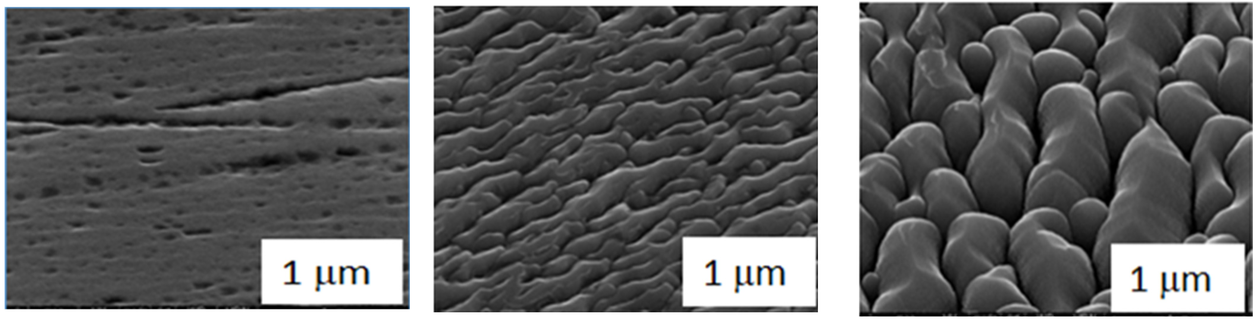
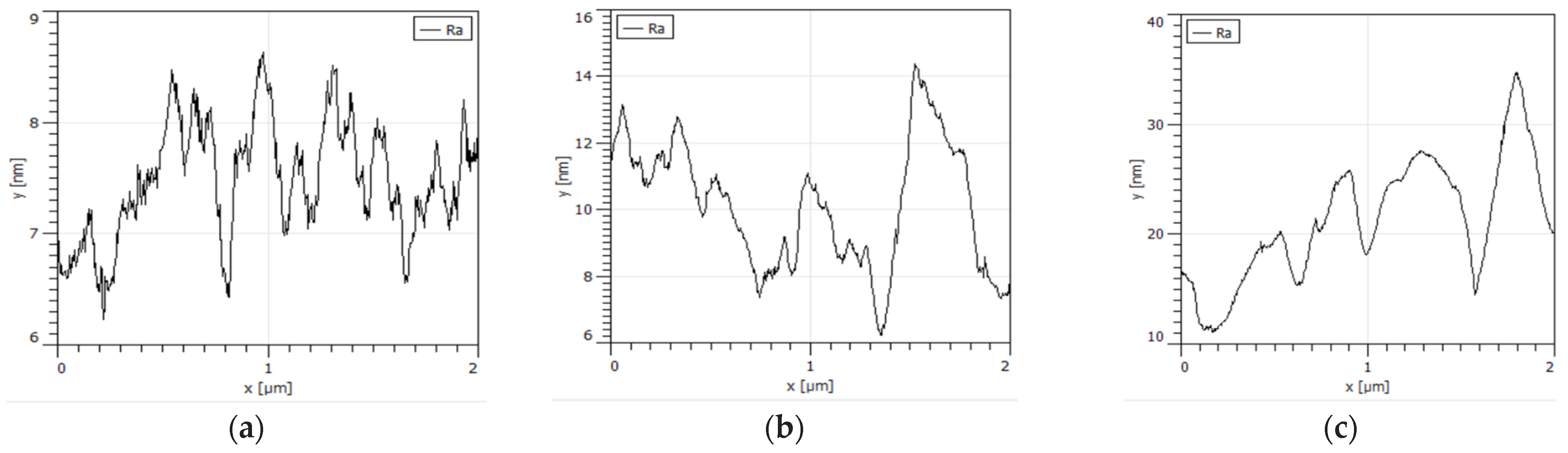
3.3. Microscopic Surface Analysis

The cross section of the coating (shown in Figure 5 for the C-43 deposited on a Si-wafer) shows the lighter (heavier elements) adhesion coating with a thickness of about 220 nm, and the thicker Cr0.35O0.53C0.12 coating (1200 nm). The Cr0.35O0.53C0.12 coating grows in columns. The tips of the columns increase the surface roughness.
The surface of the 1.2 μm thick coating is still rather smooth and the structure reproduces the substrate surface. For thicker coatings, the surface structure is dominated by the growing columns (Figure 6).
The scatting of the incident light on the rough surface and within the semitransparent columns not only increases the diffuse reflection (and reduce the specular reflection), but also increases the light absorption within the coating due to the multiple reflections and increased light path (Figure 7).

3.4. Mechanical Coating Properties

The coating adhesion was tested by scratch testing, as shown in Figure 8. The coating of sample 46 failed at a critical load of LC2 = 44 N (Figure 8c) with lateral cracking and removal of the coating from the substrate at the bottom of the scratch. A LC2 of 44 N is sufficient for application for non-cutting tool applications. At lower loads, the coating failed occasionally along the scratch length by small area coating delamination, as shown in Figure 8b, without any coating removal on the scratch bottom, but no clear LC1 value can be identified. Also cracks propagating from the scratch into the coating cannot be identified for L < LC2.
Sample C-38 shows a very low coating adherence, indicating that the reduced bias might not provide sufficient coating cracking resistance. But also, samples C-43 and C-45 show a reduced coating adherence compared to sample C-46. We associated this reduced adherence to the lower coating thickness.

3.5. Surface Energy

The surface energy σ (Table 2) depends essentially on the composition and surface texture of the coating but does not vary with does not vary with the film thickness. Absolute values are similar to chromium and CrN coatings [35,36] and it is expected that the coating surface reacts similarly to those coatings. Fingerprints can always be seen on a black shiny surface but can easily be removed for all coatings. Soiling the coating with quite aggressive media like ketchup requires a more sophisticated cleaning. Cleaning with a standard dishwashing machine program at 65 °C restored the original surface appearance. L*a*b* parameters before soiling (as listed in Table 2) and after the cleaning procedure were identical.

4. Discussion

The coating grew with a columnar structure. The columns consist of Cr and O with a ratio close to the ratio in Cr2O3. Nevertheless, X-ray diffraction did not reveal a significant percentage of crystalline Cr2O3. Eventually, the existing crystals are small, as indicated by the broad X-ray peaks. The coatings’ growth is almost X-ray amorphous, as it is frequently found in PVD coating at a low deposition temperature.
The XPS analysis of the samples shows an increasing contribution of OH binding with increasing coating thickness. During the deposition, the impingement rate of H2O at a base pressure of about 4 × 10⁻⁶ mbar is about 50 times lower than the impingement rate of the oxygen introduced into the chamber. Two effects may contribute to the increasing OH groups. Firstly, during coating deposition, the temperature of the substrate holder is increasing, associated with an increase of water vapor outgassing, although this increase is not enough to be noted by either the total pressure or in the changes in the target voltage (controlled at constant power). Secondly, the surface roughness increased, and, therefore, the surface area where the OH groups were found either bound to the surface or in the form of entrapped water vapor. We tend to believe that these OH groups are attached to the surface of the coating (especially in between the columns) and cannot easily be removed by the surface bombardment prior to the XPS measurement.
Increasing coating thickness also reveals an increasing amount of C in the form of C-C bounds. Although the sputtering conditions (pressure, target voltage and current) are kept constant during the deposition, the coating composition changes. For lower coating thicknesses, the carbon is integrated in the Cr2O3 in the form of metal carbides. For higher thicknesses, the carbon tends to form C-C compounds. The substrate temperature cannot be controlled in our experimental set-up and, of course, increases with coating time. The optical properties, nc and kc, are very sensitive to changes in the coating composition and coating structure. Analyzing the optical reflection reveals an average value for n and k throughout the coating thickness. C-C bounds generally have a low absorption coefficient for visible light. This is reflected by the extinction coefficient kc which decreases with increasing coating thickness.
The surface texture of the coating changes with the coating thickness as shown in Figure 6. The surface became much rougher, the surface roughness, as measured by AFM, increased from about ra~2 to ra > 20 nm. Highly absorbing surfaces were generally achieved by a combination of medium absorption (if the extinction coefficient is high as in metals the reflection increase according to Equation (1)) with scattering effects within the coating and due to the surface texture. Within the frame of this work, the surface texture is used to define the optical appearance. All coatings show color coordinates a* and b* < 3 and L* < 50 and have therefor a black appearance. Nevertheless, with the increasing coating thickness, L* tends to 30, or in absolute numbers, the specular reflection reduced to almost 0% and the diffuse reflection to <6% (at a wavelength of 550 nm) for the 4.8 μm thick coating. The variation of the surface structure with the thick coating allows the choice of the decorative optical appearance. The Cr0.35O0.53C0.12 coatings with a thickness > 2.4 μm tended to have a matt appearance, coatings with a thickness between 0.8 and 1.2 μm had a piano black appearance. Thinner coatings had lower absorption and, together with optical interference effects, are therefore slightly colored.
Within the frame of this work, we intended to produce coatings having optical properties which would not vary with small thickness variations. In batch coaters with two- or three-fold substrate rotation typical thickness variations are below 20%. When analyzing the color L*,a*, b* of several samples in the same batch, but in different positions (and consequently with small thickness variations) with a thickness superior 1 micron, the difference of the color is not humanly perceptible. In numeric terms, we did not observe color variations ΔC > 1.4 [37]. ΔC was calculated from Equation (3).
Δ C = Δ L 2 + Δ a 2 + Δ b 2
ΔL*2, Δa*2 and Δb*2 are the square of the difference of the respective color coordinates from two samples from the same batch, but with different coating thicknesses.
For most decorative applications, besides the optical properties, the mechanical and chemical properties of the coating determine their applicability. Applying typical procedures for the coatings by PVD processes like in situ plasma surface activation, followed by the deposition of a metallic adhesion layer (pure Cr), a good coating adherence with a critical load of LC2 = 44 N can be achieved on steel substrates. This coating adherence promises a long coating lifetime, although it must be complemented by abrasion resistance measurements.
The Cr0.35O0.53C0.12 coating is chemically quite inert. The surface energy σ = 30 mN/m is similar to Cr and CrN coatings [38]. Artificially applied stains can easily be removed by wiping (fingerprints) or dish washing (ketchup) without changing the surface’s appearance. All these findings allow the conclusion that the coating can be used in decorative applications without additional protection with a good lifetime expectancy.

5. Conclusions

Cr0.35O0.53C0.12 coatings were deposited reactive magnetron sputtering. The coatings showed a columnar structure and, with increasing thickness, the columns widen and increase the optical significantly the surface roughness. Thin coatings are semitransparent and the optical appearance is dominated by light interference effects. Coatings with a thickness of >1 μm have a constant reflectivity within the visible spectrum and a piano black appearance. With increasing thickness, the surface roughness effects dominate the appearance of the coating, with a somewhat reduced total reflectance, appears matt. For a thickness of about 5 μm, the specular reflectivity is almost neglectable (<1%) and the diffuse reflectivity (ca. 6% at λ = 550 nm) dominates the matt appearance.
Cr0.35O0.53C0.12 coatings can be deposited in a batch coating system in which some changes of the base pressure and coating thickness depending on the cleanliness and geometry are to be expected.
In the literature [39,40,41], several black coatings based on the same optical principle (thick, semi-transparent coatings, based on Al, Ti Cr in combination with O, N, C, with an index of refraction nc < 3 and 0.1 < kc < 1 can be found, but the reported variation of the surface roughness and there for the transition from piano-black to matt appearance seems to be typical for Cr0.35O0.53C0.12.
The attractive properties of the Cr0.35O0.53C0.12 are the combination of a decorative black, together with mechanical and chemical properties, which allow the application of the PVD coating without protective top coating. For a job shop coater, the Cr0.35O0.53C0.12 can be scaled from piano black appearance to matt appearance in robust process, where small variations of the base pressure and small thickness variations, typical for two- and three-fold rotation, can be accommodated and will not influence the perceptible color of the product.

Author Contributions

Validation, S.C.; Investigation, N.A. and M.A.; Resources, J.F.; Writing—review & editing, M.A. All authors have read and agreed to the published version of the manuscript.

Funding

This research was funded by Agência Nacional de Inovação within the frame of the project GREENCOAT Green Vacuum Coatings—Metalização Ecológica de Plásticos POCI-01-0247-FEDER-042785. One of the authors (Nadia Arrousse) appreciates a fellow ship grant within the project.

Institutional Review Board Statement

Not applicable.

Informed Consent Statement

Not applicable.

Data Availability Statement

Not applicable.

Conflicts of Interest

The authors declare that they have no known competing financial interest or personal relationships that could have appeared to influence the work reported in this paper.

References

  1. Bewilogua, K.; Brauer, G.; Dietz, A.; Gabler, J.; Goch, G.; Karpuschewski, B.; Szyszka, B. Surface technology for automotive engineering. CIRP Ann. Manuf. Technol. 2009, 58, 608–627. [Google Scholar] [CrossRef]
  2. Carneiro, E.; Parreira, N.M.; Vuchkov, T.; Cavaleiro, A.; Ferreira, J.; Andritschky, M.; Carvalho, S. Cr-based sputtered decorative coatings for automotive industry. Materials 2021, 14, 5527. [Google Scholar] [CrossRef] [PubMed]
  3. Ferreira, A.A.; Silva, F.J.G.; Pinto, A.G.; Sousa, V.F.C. Characterization of thin chromium coatings produced by PVD sputtering for optical applications. Coatings 2021, 11, 215. [Google Scholar] [CrossRef]
  4. Andritschky, M.; Atfeh, M.; Pischow, K. Multilayered decorative a-C:H/CrC coating on stainless steel. Surf. Coat. Technol. 2009, 203, 952–956. [Google Scholar] [CrossRef]
  5. Schossig, M.; Norkus, V.; Gerlach, G. Infrared Responsivity of Pyroelectric Detectors with Nanostructured NiCr Thin-Film Absorber. IEEE Sens. J. 2010, 10, 1564–1565. [Google Scholar] [CrossRef]
  6. Lee, J.; Kim, H.J.; Ko, Y.J.; Baek, J.Y.; Shin, G.; Jeon, J.G.; Lee, J.H.; Kim, J.H.; Jung, J.H.; Kang, T.J. Enhanced pyroelectric conversion of thermal radiation energy: Energy harvesting and non-contact proximity sensor. Nano Energy 2022, 97, 107178. [Google Scholar] [CrossRef]
  7. Pfund, A.H. The optical properties of metallic and crystalline powders. J. Opt. Soc. Am. 1933, 23, 375–378. [Google Scholar] [CrossRef]
  8. Nelms, N.; Dowson, J. Goldblack coating for thermal infrared detectors. Sens. Actuators A 2005, 120, 403–407. [Google Scholar] [CrossRef]
  9. Hao, Y.; Ye, Z.; Ye, M.; Dong, H.; Wang, L.; Du, Y. Construction and growth of black PEO coatings on aluminum alloys for enhanced wear and impact resistance. Ceram. Int. 2023, 49, 30782–30793. [Google Scholar] [CrossRef]
  10. Lin, Z.; Ma, C.; Ma, Z.; Gao, L.; Chen, W.; Chen, G. Laser etching ultra-black coating with novel anti-icing performance. Chem. Eng. J. 2023, 466, 143067. [Google Scholar] [CrossRef]
  11. Bello, M.; Shanmugan, S. Achievements in mid and high-temperature selective absorber coatings by physical vapor deposition (PVD) for solar thermal Application-A review Review. J. Alloys Compd. 2020, 839, 155510. [Google Scholar] [CrossRef]
  12. Rebouta, L.; Pitães, A.; Andritschky, M.; Capela, P.; Cerqueira, M.F.; Matilainen, A.; Pischow, K. Optical characterization of TiAlN/TiAlON/SiO2 absorber for solar selective applications Optical characterization of TiAlN/TiAlON/SiO2 absorber for solar selective applications. Surf. Coat. Technol. 2012, 211, 41–44. [Google Scholar] [CrossRef]
  13. Kam, D.; Wen, W.; Sadiq, T.O.; Idris, J. Deposition of black chromium coating for solar thermal application. J. Eng. Res. 2023, 11, 100023. [Google Scholar]
  14. Surviliene, S.; Cesuniene, A.; Juskenas, R.; Selskiene, A.; Bucinskiene, D.; Kalinauskas, P.; Juskevicius, K.; Jureviciute, I. The use of trivalent chromium bath to obtain a solar selective blackchromium coatings. Appl. Surf. Sci. 2014, 305, 492–497. [Google Scholar] [CrossRef]
  15. Saxena, V.; Rani, R.U.; Sharma, A.K. Studies on ultra high solar absorber black electroless nickel coatings on aluminum alloys for space application. Surf. Coat. Technol. 2006, 201, 855–862. [Google Scholar] [CrossRef]
  16. Ilic, B.; Czaplewski, D.; Neuzil, P.; Stancz, T.; Blough, J.; Maclay, G.J. Preparation and characterization of platinum black electrodes. J. Mater. Sci. 2000, 35, 3447–3457. [Google Scholar] [CrossRef]
  17. Pokorný, P.; Novotný, M.; More-Chevalier, J.; Dekhtyar, Y.; Romanova, M.; Davídkova, M.; Chertopalov, S.; Fitl, P.; Hruska, M.; Kawamura, M.; et al. Surface processes on thin layers of black aluminum in ultra-high vacuum. Vacuum 2022, 205, 111377. [Google Scholar] [CrossRef]
  18. Born, M.; Wolf, E. Principles of Optics; Pergamon: Oxford, UK, 1970. [Google Scholar]
  19. Wang, F.; Wu, J. Chapter 14—Applications in decorative films. In Modern Ion Plating Technology: Fundamentals and Applications; Elsevier: Amsterdam, The Netherlands, 2023; pp. 365–380. [Google Scholar] [CrossRef]
  20. Fernandes, A.C.; Cunha, L.; Moura, C.; Vaz, F.; Carvalho, P.; Le Bourhis, E.; Goudeau, P.; Rivière, J.P.; Parreira, N.M. The effect of bombarding conditions on the properties of multifunctional Ti-C-O thin films grown by magnetron sputtering. Surf. Coat. Technol. 2007, 202, 946–951. [Google Scholar] [CrossRef]
  21. Gupta, P.; Fang, F.; Rubanov, S.; Loho, T.; Koo, A.; Swift, N.; Fiedler, H.; Murmu, J.L.P.P.; Markwitz, A.; Kennedy, J. Decorative black coatings on titanium surfaces based on hard bi-layered carbon coatings synthesized by carbon implantation. Surf. Coat. Technol. 2019, 358, 386–393. [Google Scholar] [CrossRef]
  22. Xiao, W.; Jiang, X. Optical and mechanical properties of nanocrystalline aluminum oxynitride films prepared by electron cyclotron resonance plasma enhanced chemical vapor deposition. J. Cryst. Growth 2004, 264, 165–171. [Google Scholar] [CrossRef]
  23. Cerny, F.; Jech, V.; Stepanek, I.; Mackova, A.; Konvickova, S. Decorative a-C:H coatings. Appl. Surf. Sci. 2009, 256, S77–S81. [Google Scholar] [CrossRef]
  24. Chen, B.; Yang, D.; Charpentier, P.A.; Nikum, S. Optical and structural properties of pulsed laser deposited Ti:Al2O3 thin films. Sol. Energy Mater. Sol. Cells 2008, 92, 1025–1029. [Google Scholar] [CrossRef]
  25. Harish, C.; Barshilia, N.; Selvakumar, K.; Rajam, S.; Biswas, A. Structure and optical properties of pulsed sputter deposited CrxOy/Cr/Cr2O3 solar selective coatings. J. Appl. Phys. 2008, 103, 023507. [Google Scholar] [CrossRef]
  26. He, J.; Lan, X.; Liu, Z.; Jiao, D.; Zhong, X.; Cheng, Y.; Tang, C.; Qiu, W. Modification of Cr/CrN composite structure by Fe addition and its effect on decorative performance and corrosion resistance. Ceram. Int. 2021, 47, 23888–23894. [Google Scholar] [CrossRef]
  27. Cooke, K.E.; Bamber, M.; Bassas, J.; Boscarino, D.; Derby, B.; Figueras, A.; Inkson, B.J.; Rigato, V.; Steer, T.; Tee, D.G. Multilayer nitride coatings by closed field unbalanced magnetron sputter ion plating. Surf. Coat. Technol. 2003, 162, 276–287. [Google Scholar] [CrossRef]
  28. Numata, Y.; Nair, S.V.; Nakagawa, K.; Ishino, H.; Kobayashi, T.; Tokunaga, E. Optical size effect of organic nanocrystals studied by absorption spectroscopy within an integrating sphere. Chem. Phys. Lett. 2014, 601, 128–133. [Google Scholar] [CrossRef]
  29. Wang, Q.; Lai, F.; Shi, W.; Li, X.; Chen, R.; Liu, H.; Zhang, X.; Chang, Q.; Wang, Y. Synthesis and color properties of MnTiO3 black ceramic pigment. Mater. Chem. Phys. 2023, 296, 127310. [Google Scholar] [CrossRef]
  30. Carvalho, S.; Parreira, N.M.G.; Silva, M.Z.; Cavaleiro, A.; Rebouta, L. In-service behaviour of (Ti,Si,Al)Nx nanocomposite films. Wear 2012, 274–275, 68–74. [Google Scholar] [CrossRef]
  31. Tiss, B.; Bouguila, N.; Kraini, M.; Khirouni, K.; Vazquez–Vazquez, C.; Cunha, L.; Moura, C.; Alaya, S. Electrical transport of sprayed In2S3:Ag thin films. Mater. Sci. Semicond. Process. 2020, 114, 10508. [Google Scholar] [CrossRef]
  32. ISO 19403-2:2017; Paints and Varnishes—Wettability—Part 2: Determination of the Surface Free Energy of Solid Surfaces by Measuring the Contact Angle. ISO: Geneva, Switzerland, 2017.
  33. Johnson, B.; Christy, R.W. Optical constants of transition metals: Ti, V, Cr, Mn, Fe, Co, Ni, and PdP. Phys. Rev. B 1974, 9, 5056. [Google Scholar] [CrossRef]
  34. Abdullah, M.M.; Rajab, F.M.; Al-Abbas, S.M. Structural and optical characterizationof Cr2O3 nanostructures: Evaluation of its dielectric properties. AIP Adv. 2014, 4, 027121. [Google Scholar] [CrossRef]
  35. Fuentes, G.G.; Rodriguez, R.; Avelar-Batista, J.C.; Housden, J.; Montalá, F.; Carreras, L.J.; Cristóbal, A.B.; Damborenea, J.J.; Tate, T.J. Recent advances in the chromium nitride PVD process for forming and machining surface protection. J. Mater. Process. Technol. 2005, 167, 415–421. [Google Scholar] [CrossRef]
  36. Douard, A.; Maury, F. Chromium-based coatings by atmospheric chemical vapor deposition at low temperature from Cr(CO)6. Surf. Coat. Technol. 2005, 200, 1407–1412. [Google Scholar] [CrossRef]
  37. Gomez, O.; Perales, E.; Chorro, E.; Burgos, F.J.; Viqueira, V.; Vilaseca, M.; Martınez-Verdu, F.M.; Pujol, J. Visual and instrumental assessments of color differences in automotive coatings. Color Res. Appl. 2016, 41, 384–391. [Google Scholar] [CrossRef]
  38. Chappé, J.M.; Vaz, F.; Cunha, L.; Moura, C.; de Lucas, M.M.; Imhoff, L.; Bourgeois, S.; Pierson, J.F. Development of dark Ti(C,O,N) coatings prepared by reactive sputtering. Surf. Coat. Technol. 2008, 203, 804–807. [Google Scholar] [CrossRef]
  39. Ono, K.; Wakabayashi, M.; Tsukakoshi, Y.; Abe, Y. Decorative black TiCxOy film fabricated by DC magnetron sputtering without importing oxygen reactive gas. Appl. Surf. Sci. 2016, 364, 69–74. [Google Scholar] [CrossRef]
  40. Nedfors, N.; Tengstrand, O.; Lewin, E.; Furlan, A.; Eklund, P.; Hultman, L.; Jansson, U. Structural, mechanical and electrical-contact properties of nanocrystalline-NbC/amorphous-C coatings deposited by magnetron sputtering. Surf. Coat. Technol. 2011, 206, 354–359. [Google Scholar] [CrossRef]
  41. Andersson, M.; Högström, J.; Urbonaite, S.; Furlan, A.; Nyholm, L.; Jansson, U. Deposition and characterization of magnetron sputtered amorphous Cr-C films. Vacuum 2012, 86, 148–1416. [Google Scholar] [CrossRef]
Figure 1. XRD diffraction spectrum of sample C-46 in the Θ-2Θ configuration. For comparison, the X-ray spectrum of the stainless-steel substrate (with background subtraction) and the expected peak positions of Cr2O3 (Escolaite) are shown also.
Coatings 13 01838 g001
Figure 2. (a) Deconvoluted binding energy Ebind [eV] of the oxygen peak for samples C-48, C-43 and C-46 as determined by XPS. (b) Deconvoluted carbon peak for samples C-48, C-43 and C-46 as determined by XPS.
Coatings 13 01838 g002aCoatings 13 01838 g002b
Figure 3. (a) Specular reflection of all samples and simulation of specular reflectance of samples C-43 and C-48. (b) nc and kc used in the simulation of the reflectance spectra of samples C-43 and C-48.
Coatings 13 01838 g003
Figure 4. (a) Diffuse reflectance of all samples. (b) L*a*b* parameters. Samples are in the sequence of increasing thickness. Sample C-38 was produced at a lower bias than samples C43-48.
Coatings 13 01838 g004
Figure 5. Cross section of coating C-43, as deposited on a polished Si wafer.
Coatings 13 01838 g005
Figure 6. SEM pictures of the sample surface and quantification of the surface structure by AFM. (Please note the variation of scale in the y-axes for the AFM quantification). (a) Sample C-43 with thickness 1.2 μm. (b) Sample C-45 with thickness 2.4 μm. (c) Sample C-46 with thickness 4.8 μm.
Coatings 13 01838 g006aCoatings 13 01838 g006b
Figure 7. Schematic representation of incoming light and reflection and scattering in a thin film with columnar growth.
Coatings 13 01838 g007
Figure 8. (a) Microscopic analysis of the scratch at a load between 0 and 26 N. (b) Microscopic analysis of the scratch at a load of 6 N. (c) Microscopic analysis of the scratch at the critical load LC2 = 44 N.
Coatings 13 01838 g008aCoatings 13 01838 g008b
Table 1. Coating deposition conditions.
SamplesBase
Pressure [mbar]
Power Cr [W]Power C [W]Total Pressure
[mbar]
Flow Ar [sccm]Flow O2 [sccm]Bias [A]Bias [V]Deposition Time [min]
C-381.2 × 10−660010001.0 × 10−321.280.51−65450
C-431.2 × 10−660010001.0 × 10−321.280.53−85240
C-454.0 × 10−660010001.0 × 10−321.280.55−85450
C-464.4 × 10−660010001.0 × 10−321.280.54−85840
C-481.2 × 10−660010001.0 × 10−321.280.54−8590
Table 2. Experimental results for all samples (except coating on sample C-48, which was too thin for EDX at a beam energy of 15 KeV) and scratch test measurements. There might be some small influence of the metallic adhesion layer on the compositional analysis of sample C-43 applying the semi-infinite ZAF model and scratch test measurements.
SampleEDX Composition
[at %]
Thickness
[μm]
XPS Composition [at %]Critical Load LC2 [N]Surface Energy σ
[mN/m]
CrOCCrOC
C-3835.651.912.52.4 826.6
C-4335.253.411.41.228.252.019.81230.8
C-4533.452.114.52.4 1230.7
C-4636.052.411.64.815.437.846.84426.3
C-48---0.4536.054.79.3-27.0
Disclaimer/Publisher’s Note: The statements, opinions and data contained in all publications are solely those of the individual author(s) and contributor(s) and not of MDPI and/or the editor(s). MDPI and/or the editor(s) disclaim responsibility for any injury to people or property resulting from any ideas, methods, instructions or products referred to in the content.

