Article

Influence of AC-DC-AC Cycling with Hydrostatic Pressure on Accelerated Protective Performance Test of Glass Flake Epoxy Coating

1
State Key Laboratory for Marine Corrosion and Protection, Luoyang Ship Material Research Institute, Qingdao 266237, China
2
School of Chemistry and Chemical Engineering, Ocean University of China, Qingdao 266100, China
3
Xiamen Sunrui Ship Coating Co., Ltd., Xiamen 361101, China
*
Author to whom correspondence should be addressed.
Coatings 2023, 13(11), 1843; https://doi.org/10.3390/coatings13111843
Submission received: 28 September 2023 / Revised: 21 October 2023 / Accepted: 24 October 2023 / Published: 27 October 2023

Abstract

:
To achieve fast testing of the barrier properties of organic coatings, immersion tests, AC-DC-AC tests, and coupled tests of AC-DC-AC with hydrostatic pressure were conducted in seawater for a glass flake epoxy coating. Electrochemical impedance spectroscopy (EIS) was used to characterize the degradation processes of the coating during the tests, and the surface of the coating was analyzed using an optical microscope, scanning electron microscope (SEM), and a Fourier transform infrared spectrometer (FTIR). The results showed that periodic cathodic polarization coupled with high hydrostatic pressure can accelerate the degradation of a coating by facilitating the diffusion and uptake of electrolyte and the delamination of the coating. The coupled test method has the largest acceleration due to the synergetic effect of AC-DC-AC and hydrostatic pressure.

1. Introduction

Corrosion is a big challenge for marine ships and offshore structures made of steel due to the aggressive service environment [1]. Marine corrosion damages the steel structures with a reduction of the thickness and even perforation, which affect the reliability and safety of the ship structures and offshore installations. This may not only cause huge economic costs, but also lead to catastrophic consequences in some terrible cases [2,3].
Organic coatings have been widely used to protect steel structures from corrosion and are some of the most common and cost-effective methods for corrosion protection. Generally, organic coatings are applied to metallic surfaces to provide protection mainly by isolating the substrate from direct contact with the corrosive media (barrier effect), and sometimes also by producing corrosion inhibition with chemical additives (inhibitive effect) and/or cathodic protection with sacrificial active metallic powders (galvanic effect) [4,5]. Anticorrosive organic coatings usually have complex formulations consisting of mixtures of binders, pigments, fillers, and other additives [5]. The protection of metallic structures by organic coatings depends principally on the barrier properties of the coatings and the interfacial adhesion between the coatings and the substrates, as well as the bonding between pigments and resin binders [5,6]. However, it is well known that the barrier performance of a coating to corrosive media such as water and other species is closely related to the integrity of the coating, which depends on the chemistry and structure of the coating as well as the application process. This is often affected by environmental and mechanical attacks [7].
Coatings with high performance and long durability are usually required for the protection of marine ships and offshore structures considering the severely corrosive environment and the great economic impact with coating maintenance and repair. For example, the protective coatings in seawater ballast tanks of marine ships are stipulated to achieve a target coating life of over 15 years in the IMO regulations called Performance Standards for Protective Coatings (PSPC) [8,9]. Generally, epoxy-based coatings are applied onto the steel substrate to obtain a minimum dry film thickness of 300~400 µm following the strict application procedures to achieve this purpose [8,10]. To evaluate the qualified performance of the applied coating, laboratory tests in a simulated working environment, usually with accelerating factors, are often conducted [9,11]. There have been some standardized test methods used to evaluate the protective coating systems for marine and offshore applications, however, the time required to perform such tests can be lengthy, sometimes lasting thousands of hours [11,12,13]. For the development of new types and more effective protective coatings, rapid assessment methods of the protective performance of coatings are needed, particularly for the screening and comparison of different coatings [14,15].
The principles for the accelerated testing of organic coating are generally based on applying accelerating factors (intensifying environmental stresses) to expedite the degradation of the protective coating without changing the basic failure mode and mechanism of the coating under service [16]. These accelerators include UV radiation, temperature, humidity, alternative immersion, salt spray, cyclic corrosion test, cathodic polarization, and so on [17,18,19], which should be selected for the specific testing according to the service environment and performance requirements of the coatings. Sometimes multiple accelerating factors are combined in the testing to achieve synergetic effects [20].
For the corrosion control of steel structures immersed in seawater, coatings are generally used in combination with cathodic protection to realize efficient and cost-effective protection [1,9]. However, cathodic polarization at too negative potential will provide over-protection, promoting hydrogen evolution and delamination of the coating. Based on the effect of cathodic polarization on the degradation of organic coating, an accelerated cyclic electrochemical testing technique (AC-DC-AC method) has been developed, which incorporates electrochemical impedance spectroscopy (EIS, AC) for the characterization of coating conditions and cathodic polarization (DC) for the acceleration of coating degradation [21,22]. EIS as an in situ, non-destructive, fast, and sensitive technique is used to monitor the changes of protective performance of the coatings during the accelerated testing [23,24]. Each cycle of AC-DC-AC includes a first AC step of EIS measurement at open-circuit potential, then a DC step under cathodic polarization at a constant potential for a selected period, followed by the AC step again after the relaxation process and realization of a new equilibrium [21]. This cycle can be repeated until the end of testing when the coating has presented a distinguishable deterioration. The AC-DC-AC testing method has been applied to rapidly assess the corrosion protection of different types of organic coatings, oxide films, and coatings with different formulations and preparation procedures [14,18,25,26,27,28,29,30,31]. Some modifications on this accelerated testing method have also been carried out [32,33,34,35,36]. With replacing the DC step by an alternate cathodic polarization and anodic polarization during the AC-DC-AC test, the corrosion damage of a steel sample with an organic coating can be further accelerated with enhancing both cathodic and anodic processes in the same way as that in natural immersion conditions [33,34]. A modified AC-DC-AC test procedure was reported with a combination of EIS measurements, cathodic polarization, and wet and dry cycles [35,36], where the mechanical stress produced by wet/dry process can further promote the deterioration of coatings [35]. Moreover, a two-stage AC-DC-AC approach with different cathodic polarization parameters at the first and second stages was used for rapid assessment of organic coatings, which can approximate the degradation processes of coating in the neutral salt spray test [32].
In recent years, with the increase of concern of corrosion and protection of subsea assets in deep-sea water, the effect of hydrostatic pressure on material performance, including protective performance of organic coatings, has been studied extensively [37,38,39,40,41,42,43,44,45]. It has been demonstrated that high hydrostatic pressure can speed water diffusion and absorption, increase interfacial defects, and reduce wet adhesion of the coatings [44,45]. Therefore, hydrostatic pressure can also be considered as an important accelerating factor for fast evaluation of the performance of protective coatings. However, to the best of our knowledge, the modified accelerated testing of organic coating under the coupled condition of AC-DC-AC cycling with hydrostatic pressure has never been reported.
In this work, a commercial glass flake epoxy coating, a typical marine coating of high protective performance that needs to be evaluated by a fast test method, was tested under different conditions, including the usual immersion test in seawater, rapid AC-DC-AC test, and the test with both accelerators of periodically cathodic polarization and high hydrostatic pressure. The deterioration of the coating was monitored using EIS during all the tests, and the influence of the AC-DC-AC coupled with hydrostatic pressure on the accelerated degradation of the epoxy coating was discussed. It is expected to provide some useful support for the development of a new, modified accelerated testing protocol for marine coatings.

2. Experimental

2.1. Specimen Preparation

The plate of Q235 carbon steel was used as the coating substrate, which was machined into circular specimens with a diameter of 40 mm and a thickness of 10 mm. The substrates were prepared by sandblasting to grade Sa 2 ½ at first, and then degreased with acetone (C3H6O, AR) and alcohol (C2H5OH, AR), which was produced by Sinopharm Chemical Reagent Co., Ltd. (Shanghai, China). The coating used for testing was a commercial glass flake epoxy coating typed as 725-H53-38, with epoxy resin 618 as component A, and alicyclic amine curing agent as component B, and adding proper amount of glass flake to reinforce coating barrier performance, which was produced by Xiamen Sunrui Ship Coating Co., Ltd. (Xiamen, China). The paint was brushed on the prepared steel substrate with a dry film thickness of 100 ± 10 μm. The coated specimens were encapsulated with epoxy resin, leaving a circular testing area with a diameter of 30 mm exposed. The coated specimens were conditioned for 7 days before immersion tests.

2.2. Immersion Tests

The immersion tests were conducted in natural seawater at room temperature (25 ± 1 °C) under an atmospheric pressure (0.1 MPa). The seawater was taken from the coastal area of Jiaozhou Bay in Qingdao, China, which has a salinity of 31.4‰, a dissolved oxygen content of 6.7 mg/L, and a pH value of 8.1. For the immersion test under an atmospheric pressure, the specimen was immersed in a glass container filled with seawater.

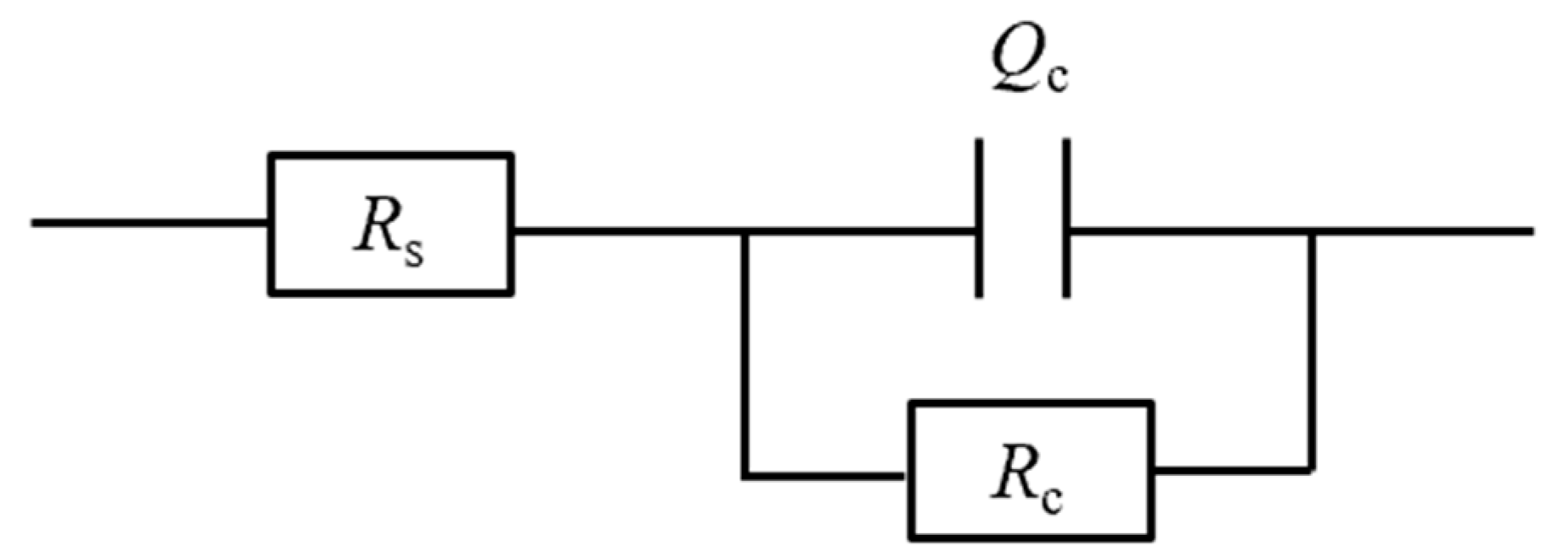
2.3. EIS Measurement

The EIS spectra of the coating specimens were recorded during the immersion tests in seawater at atmospheric pressure. EIS spectra were also measured during the AC-DC-AC tests in the AC processes under the atmospheric pressure and the hydrostatic pressure of 10 MPa. A three-electrode electrolytic cell was used for the EIS measurement, with the coated steel specimen and a platinum foil used as the counter electrode. The working area of the coated specimen as the working electrode, a solid Ag/AgCl/seawater electrode as the reference electrode, was 7.1 cm2 with the other areas encapsulated in epoxy resin. The electrochemical workstation of CS353 controlled by a software of CorrTest CS Studio (6.3.1128.9) (Wuhan Corrtest Instrument Co., Ltd., Wuhan, China) was used for the EIS measurement of the coated specimen at the open-circuit potential in seawater at room temperature. The amplitude of the AC perturbation signal was 20 mV rms. The scanning frequency was in the range of 100 kHz~10 mHz. After the tests, the EIS data were fitted using a ZSimpWin software (3.6) (AMETEK Scientific Instruments, Oak Ridge, TN, USA).

2.4. AC-DC-AC Tests at Atmospheric and Hydrostatic Pressures

The test method of AC-DC-AC is an accelerated cyclic electrochemical technique to evaluate the anticorrosive properties of organic coatings, which has been described in the ISO standard (ISO 17463) in detail [21]. The initial state of the coating was characterized using EIS at the open-circuit potential in seawater, which was the AC step. Then, the coated specimen was applied with a cathodic polarization at −10 V (vs. OCP) for 1 h followed by a relaxation process for 2 h to restore the stable OCP state, which was taken as the DC step. In consideration of the highly protective performance of the glass-flake epoxy coating, the highly negative DC potential of −10 V (vs. OCP) was used in the accelerated testing. The EIS measurement was conducted again to determine the new state of the coating (AC step). The above AC-DC-AC steps as a testing cycle were repeated until the degradation of the coating was able to be distinguished obviously.
For the AC-DC-AC test under a hydrostatic pressure of 10 MPa in seawater, a specific testing device was used to apply and maintain the water pressure automatically in the cylindrical testing chamber by a high-pressure pump using seawater as the working fluid. An electrochemical interface with three electrodes penetrating through the cover of the testing chamber was also attached to the testing apparatus. The connecting points at the specimen, reference electrode, and counter electrode with the conducting wires were sealed reliably with epoxy resin. The detailed description of the testing apparatus with adjustable hydrostatic pressure and an electrochemical interface can be found in the ISO 5668:2023 standard and other literature [46,47]. The AC-DC-AC tests at atmospheric pressure and 10 MPa hydrostatic pressure were all implemented in seawater at ambient temperature.

2.5. Surface Characterization

The macroscopic morphologies of the coated steel samples were observed and recorded using a digital camera (D7100 from Nikon, Tokyo, Japan), and the microscopic features of the coating samples were characterized by a 3D video microscope (HIROX KH-8700 from HIROX company, Tokyo, Japan), and a field emission scanning electron microscope (FE-SEM, ULTRA55, ZEISS, Jena, Germany). The chemical structural characteristics of the initial sample and the sample surface after coupling environmental testing were analyzed using a Fourier transform infrared spectrometer (Nicolet iS10 from Thermo Fisher Scientific Inc., Waltham, MA, USA), ranging from 4000 cm−1 to 500 cm−1.

3. Results and Discussion

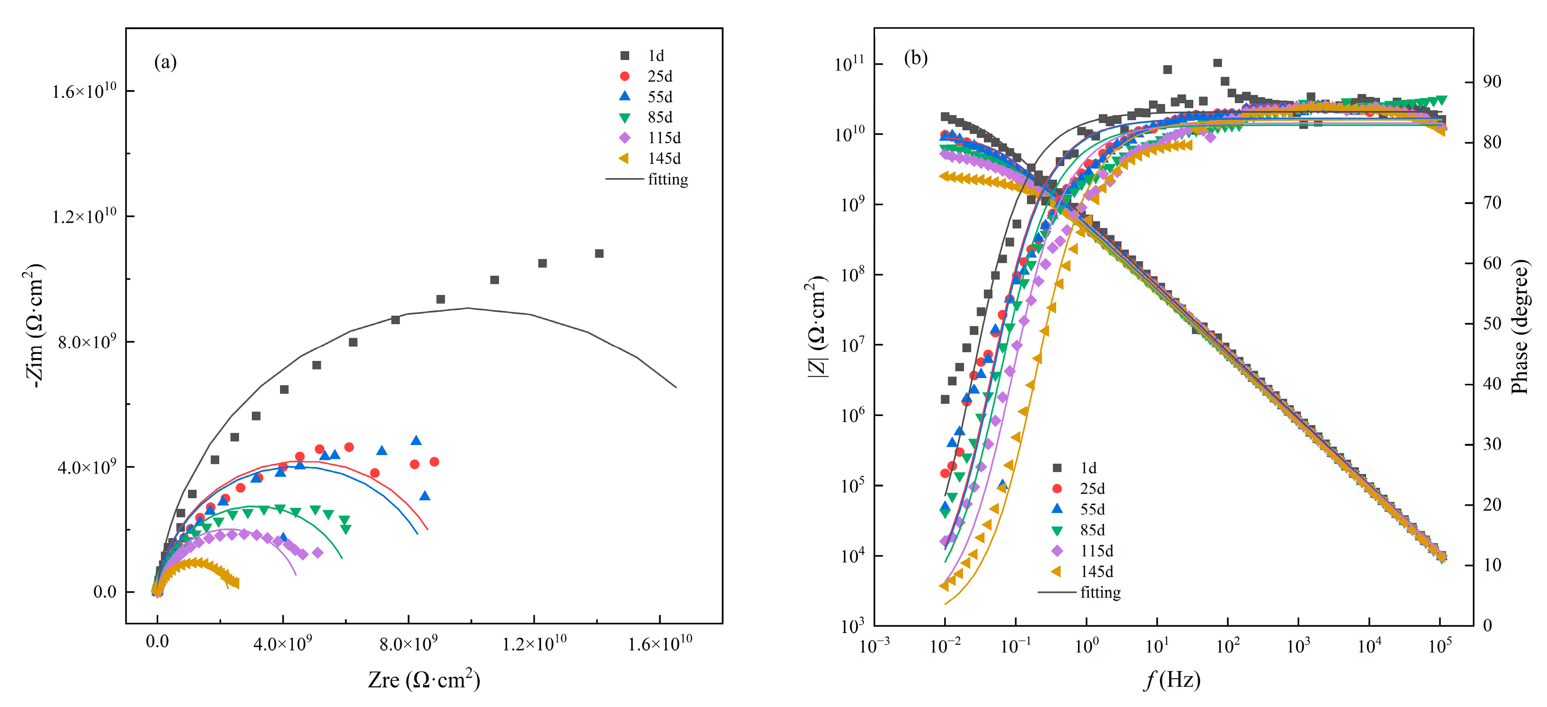
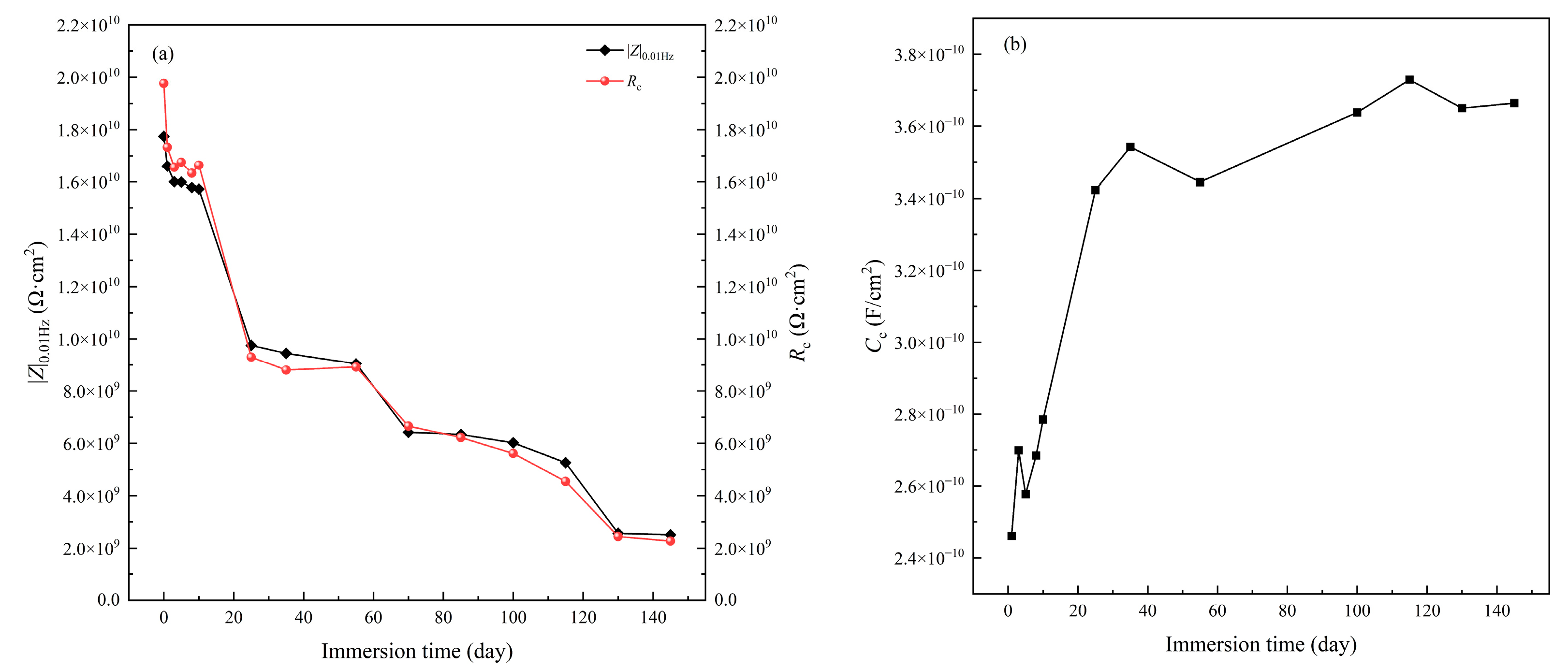
3.1. Immersion Test under Atmospheric Pressure

The immersion test of the coated sample was carried out in seawater at atmospheric pressure for a duration of 145 d. The EIS spectra of the coating/metal sample recorded at different immersion times can reflect the evolution of protective performance of the coating and the change in the electrochemical reaction process at the coating/metal interface during the immersion test [48]. Figure 1 shows the EIS spectra of the glass flake epoxy coating sample immersed in the static seawater at atmospheric pressure. It can be seen that the Nyquist plots (Figure 1a) are composed of single capacitive arcs, and the phase angles are relatively high with only one peak covering the high-frequency and intermediate frequency regions in the Bode plots (Figure 1b), indicating that there is only one time constant in the EIS characterization. The EIS spectra demonstrate that no electrochemical corrosion occurred at the surface of the steel at this stage [49]. With the immersion going on, the sizes of the capacitive arcs decreased gradually, the peaks of phase angles lowered and narrowed, and the impedance moduli at low frequency reduced, which implies that the coating is degraded with its barrier properties [50]. The equivalent circuit shown in Figure 2 can be used to fit the EIS data of an organic coating with one time constant [49,50]. Here, Rs is the solution resistance, Rc is the coating resistance (pore resistance), and Qc represents the coating capacitance. In consideration of the dispersive effect caused by the unevenness of the coating surface, the constant phase element (Qc) is used to replace the coating capacitance Cc in the equivalent circuit to improve the simulation [51,52].
Figure 3 shows the changes of the coating resistance Rc and coating capacitance Cc with immersion time. The evolution of the impedance modulus |Z|0.01Hz at low-frequency (f = 0.01 Hz) with immersion time is also shown in Figure 3. It can be found that the value of |Z|0.01Hz and the coating resistance Rc of the coated sample present almost the same variation with time during the test period and decreased quite fast in the first period of about 20 days, and then reduced gradually. The coating resistance lowered by an order of magnitude after immersion for 145 d, but remained at about 2.51 × 10⁹ Ω·cm2, which proves that the coating still has an excellent protective performance [53]. Generally, the failure of the organic coating with corrosion of metallic substrate occurs when the coating resistance Rc falls below 107 Ω·cm2 [54]. The coating capacitance presents an adverse change with immersion time, as shown in Figure 3b, which can be ascribed to the water uptake in the coating. Since the dielectric constant of water (H2O) is much larger than that of general dry organic coatings, as more water molecules permeate into the coating through the defects like micropores and pinholes, the dielectric constant of the coating increases, leading to an increase in Cc [55,56]. It can also be seen that the coating capacitance increases fast in the first 20 days of immersion in seawater, and then increases continuously and slowly, indicating that water diffuses into the coating at different speeds during immersion. The Cc tends to a stable state with time at the later stage of the immersion, demonstrating the water uptake is approaching to saturation gradually [54].

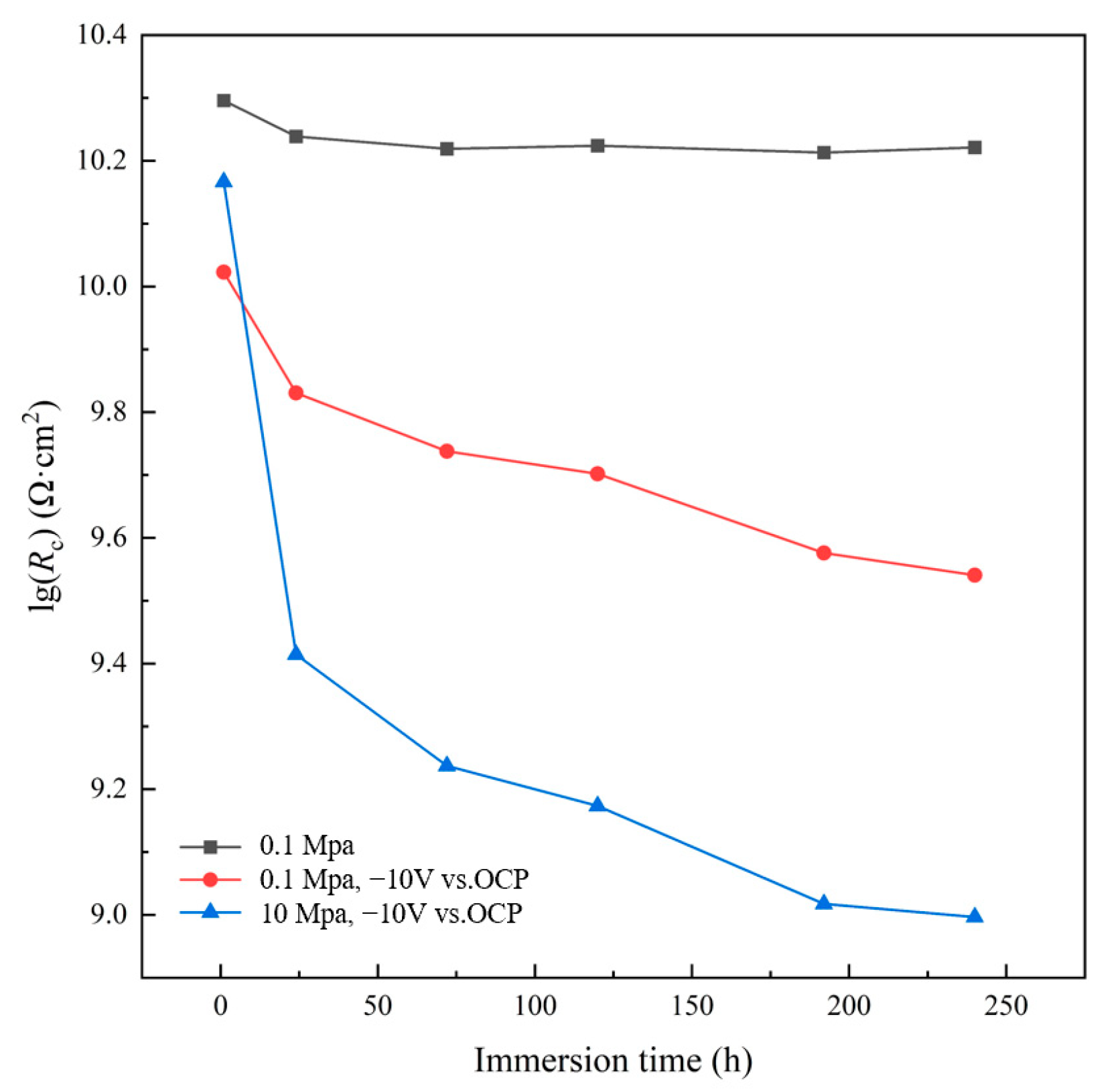
3.2. AC-DC-AC Test under Atmospheric Pressure

Figure 4 presents the EIS spectra of the glass flake epoxy coating sample recorded in seawater at different cycles of AC-DC-AC test under atmospheric pressure. It can be seen that with soaking for 10 days (that is, 80 cycles), the characteristics of the EIS spectra of the sample are similar to those with the immersion test in seawater under the atmospheric pressure, showing only one time constant, which suggests the coating still has a good protective performance to prevent aggressive electrolytes from reaching the substrate and initiating corrosion. As the testing goes on with more AC-DC-AC cycles, the impedance of the coating decreased, demonstrating the gradual degradation of the coating performance. However, the impedance at low frequency |Z|0.01Hz of the coating under this testing condition drops fast with time obviously as compared with the usual immersion test. The |Z|0.01Hz value of the glass flake epoxy coating is dropped by an order of magnitude of 109 Ω·cm2 after soaking for only 24 h (eight cycles). It is lowered continuously to about 3.99 × 10⁹ Ω·cm2 at the end of the test. The results testify that AC-DC-AC test can accelerate the degradation of the protective coating with high performance [7,8]. The EIS spectra have also been simulated using the equivalent circuit model in Figure 2. The fitting results and related analyses are provided in the next section for the convenience of comparison.

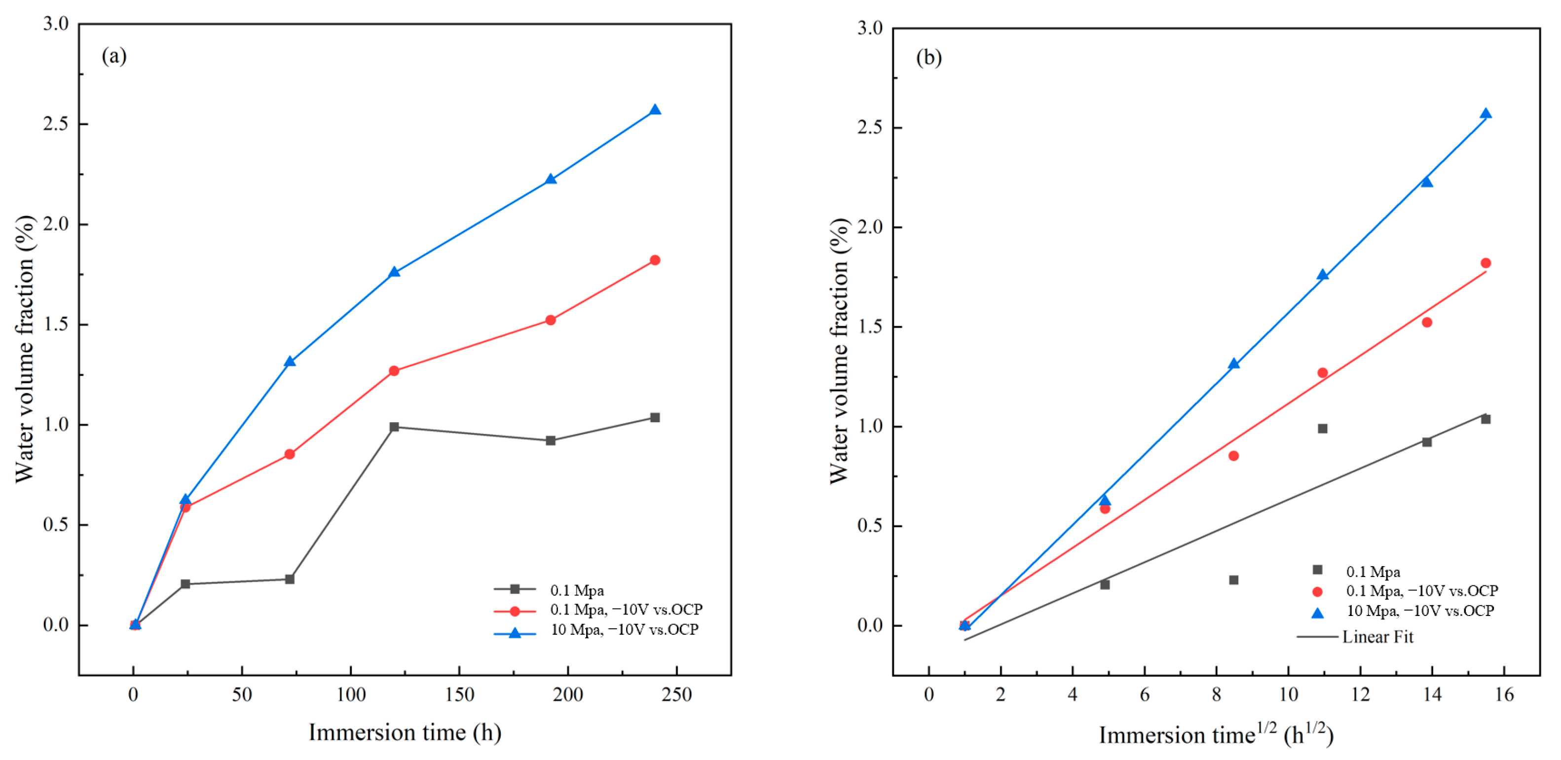
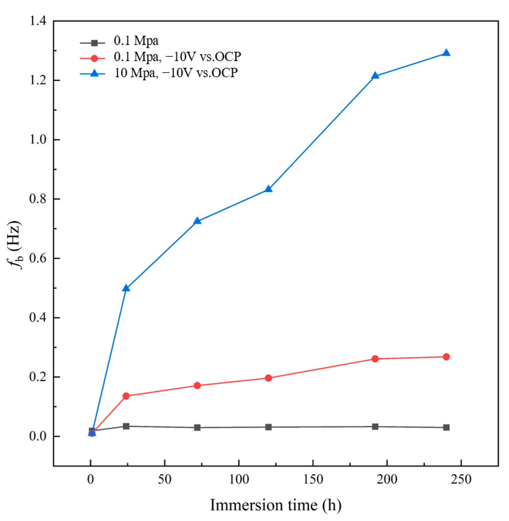
3.3. AC-DC-AC Test under Hydrostatic Pressure

Figure 5 shows the EIS spectra of the glass flake epoxy coating sample recorded at different cycles during the AC-DC-AC test in seawater under a hydrostatic pressure of 10 MPa. Under the coupled condition, the EIS spectra of the coating still showed the characteristics of one time constant in the whole testing period. The lack of another time constant in the low frequency range demonstrates that the electrochemical activity of the steel substrate at the coating/steel interface is still very low and corrosion has not occurred [16,54]. As the testing cycles or immersion time increased, the radius of the capacitive arc and the impedance modulus of the coating reduced significantly at the first stage (in the first 8 cycles), and then decreased further with ongoing testing. The |Z|0.01Hz value of the glass flake epoxy coating dropped from the initial value of over 1010 Ω·cm2 by an order of magnitude approaching to 108 Ω·cm2 at the end of testing after 80 cycles. The degradation of the coating accelerated further under the coupled testing conditions with AC-DC-AC cycling and high hydrostatic pressure as compared to the standard AC-DC-AC method. The experimental results prove that both the application of periodical cathodic polarization and the high hydrostatic pressure can provide significant driving stress for the coating degradation process of protective performance and promote the failure of the organic coating.
The low-frequency impedance modulus of the coating can effectively reflect the overall protective performance of organic coating [57]. Figure 6 and Table 1 show the change of |Z|0.01Hz value of the glass flake epoxy coating with time under the three testing conditions. The |Z|0.01Hz value of the coating immersed in seawater at atmospheric pressure decreases slowly from 1.77 × 10¹⁰ Ω·cm2 at the beginning to 1.57 × 10¹⁰ Ω·cm2 after immersion for 240 h, indicating that the coating remains in a good condition and still has excellent protective properties [58]. After testing for the same time in seawater, the |Z|0.01Hz value of the coating under the AC-DC-AC cycling condition at atmospheric pressure is decreased from the initial 1.19 × 10¹⁰ Ω·cm2 to 3.99 × 10⁹ Ω·cm2, while the |Z|0.01Hz is reduced from 1.44 × 10¹⁰ Ω·cm2 to 1.06 × 10⁹ Ω·cm2 for the coupled test with AC-DC-AC cycling and high hydrostatic pressure. According to Figure 3a and Figure 6, it is interesting to note that it takes more than 120 days for the |Z|0.01Hz value of the coating to drop to about 4.00 × 10⁹ Ω·cm2 during the immersion test in seawater at atmospheric pressure, and it takes 10 days to lower to about this |Z|0.01Hz value in the AC-DC-AC test at atmospheric pressure, In contrast, it takes only one day to achieve the same |Z|0.01Hz value when tested by using AC-DC-AC cycling coupled with the high hydrostatic pressure. Obviously, the testing method by AC-DC-AC coupled with hydrostatic pressure has the strongest impact of acceleration on the degradation of barrier properties of the epoxy coating, and the modified AC-DC-AC method with hydrostatic pressure can shorten the testing time significantly.
The EIS spectra were also fitted using the same equivalent circuit in Figure 2 for the coating tested under the coupled conditions with AC-DC-AC and hydrostatic pressure. The EIS fitting results of the glass flake epoxy coating under different testing conditions are given in Table 1.
Coating resistance Rc is a crucial parameter to characterize the anticorrosion performance of coatings [53]. The change curves of coating resistance Rc with immersion time under different testing conditions are shown together in Figure 7 and Table 1. It can be seen that Rc presents a similar tendency to the impedance modulus |Z|0.01Hz. The initial coating resistance is 1.98 × 10¹⁰ Ω·cm2 of the coating tested with immersion in seawater at atmospheric pressure, and it is dropped to 1.66 × 10¹⁰ Ω·cm2 after soaking for 120 h. As the immersion time prolongs, more corrosive media penetrates the coating to form continuous pathways, leading to further decreasing of Rc [24]. The Rc of the coating is dropped to 1.63 × 10¹⁰ Ω·cm2 after soaking in seawater at atmospheric pressure for 240 h. In the test by AC-DC-AC cycling at atmospheric pressure, the initial Rc of the coating is 1.05 × 10¹⁰ Ω·cm2, and the Rc of the coating drops to 3.47 × 10⁹ Ω·cm2 after soaking for 240 h. This result shows that the applied cathodic potential promotes coating degradation [35]. In the test by AC-DC-AC coupled with high hydrostatic pressure, the Rc is dropped from initial 1.47 × 10¹⁰ Ω·cm2 to 9.92 × 10⁸ Ω·cm2 after soaking for the same time. The evolution of Rc with time also demonstrates the further acceleration effect by DC cathodic polarization coupled with hydrostatic pressure in the protective performance testing of organic coatings.
Diffusion of corrosive media such as water, ions, and oxygen into the coating is the main cause of organic coating failure at the early stage. The water absorption kinetics analysis of the coating can reflect the barrier ability and the change of the internal defects of the coating, which are important factors for evaluating the failure process of organic coatings. The uptake of water in the coating can be calculated by the Brasher–Kingsbury Formula (1) as follow [59,60]:
Xv = log(Ct/C0)/log(εw)
where Xv is the water volume fraction in the organic coating; C0 and Ct are the initial coating capacitance and the coating capacitance at time t, respectively; and εw is the relative permittivity of water, taking 80 at room temperature [59,61]. The coating capacitance Ct can be derived from EIS spectra at a fixed high frequency (f = 100 kHz) according to the following Formula (2) [61]:
Ct = −1/(2πfZ″)
where Z″ is the imaginary part of the impedance at 100 kHz. The initial coating capacitance C0 of dry film can be acquired from extrapolation of the capacitance curve to t = 0.
Figure 8 is a curve of water absorption and linear fitting in the glass flake epoxy coating as a function of immersion time in seawater under the different testing conditions. It can be seen that in the three testing environments, the water volume fraction in the coating continues to rise during the testing period of 240 h. The slope of the water absorption curve of the coating is the smallest in the test of usual immersion in seawater at atmospheric pressure, and the water uptake of the coating reaches 1.03% after 240 h of immersion. The diffusion process of water into the coating in the test of AC-DC-AC cycling at atmospheric pressure is faster than that in the immersion test at atmospheric pressure, and finally reaches 1.82% after 240 h, which should be due to the acceleration effect of cyclic cathodic polarization leading to the deterioration of the coating. The diffusion of water into the coating in the test by AC-DC-AC cycling coupled with hydrostatic pressure is the fastest among the three testing methods, which should be related to the fact that high hydrostatic pressure accelerates the penetration of water and other corrosive media into the coating, so the water absorption rate of the coating increases significantly [45]. The water absorption rate reaches 2.57% after soaking for 240 h in this case. The average water diffusion velocity during the testing period is the largest under the test of AC-DC-AC cycling coupled with high hydrostatic pressure, and the average diffusion velocity of water in the coating during the AC-DC-AC test at atmospheric pressure is also higher than that during the usual immersion test.
Moreover, although the slopes of the water uptake curves are decreased gradually with time, the water volume fractions of the coating have not entered into a stable state by presenting platforms on the water absorption curves, which indicates that the water uptake is not completely saturated in the coating after the testing for 240 h in each case [54,61]. Figure 8b shows the linear fitting results of water sorption with the square root of immersion time t for all the three tests, indicating that water uptake has a linear relationship with t1/2. This demonstrates that the water diffusion in the coating conforms to the Fick diffusion law during the testing period of 240 h [44,45]. Both the cyclic cathodic polarization and the high hydrostatic pressure can promote the penetration of corrosive media such as water into the hard-to-diffuse area of the coating, thus increasing the water absorption of the coating [62]. It has been reported in the literature that high hydrostatic pressure can increase the diffusion coefficient of water in the epoxy coating with glass flake-filled [44,45]. This is further explained by Shao et al. [44], where hydrostatic pressure can induce microcracks around glass flake fillers and provide faster pathways for water penetration.
The breakpoint frequency fb has a good correlation with the delaminated area of the coating, with a higher fb corresponding to a larger delamination area at the organic coating/steel substrate interface [24]. The frequency of fb can be easily acquired from the Bode diagram, which is the frequency at the phase angle of 45°. Figure 9 shows the variation of fb of the coating with time under different testing conditions. As immersion time is increased, the fb is increased fast initially and then gradually under all the testing conditions, implying the enhancement of the delamination with time. The coating under the test of AC-DC-AC at atmospheric pressure has higher fb than the coating with the usual immersion test, demonstrating the accelerated effect of DC cathodic polarization. The fb of the coating under the test coupled with AC-DC-AC and hydrostatic pressure is the highest and much higher than that under AC-DC-AC test, indicating the combined test condition is very aggressive and has a very intensive acceleration to the degradation of the coating. In general, the degree of delamination can be determined by fb, according to the following equations [61,63]:
fb = K·α
K = 1/(2π·ε·ε0·ρ)
α = Ad/A
where α is the delaminated area ratio; Ad and A are the equivalent delaminated area and the working area for testing, respectively; ε0 = 8.85 × 10⁻¹⁴ F cm−1, which is the vacuum permittivity; ρ is the resistivity and ε is the dielectric constant of the coating, for the epoxy coating; and ε = 4 and ρ = 6.27 × 10⁶ Ω·cm [61,63]. K can be taken approximately as a constant; thereby, the delaminated area of the coating is proportional to fb [24]. The delaminated area and the delaminated area ratio of the coating samples under the three testing conditions calculated using the above formulas are shown in Table 2.
The results show that the delaminated area and the delaminated area ratio are very small for the coating with immersion test in seawater at atmospheric pressure, while the values of Ad and α of the coating after AC-DC-AC test are almost nine times as large as that for the sample with immersion test. The results demonstrate that the AC-DC-AC test accelerates the delamination of the coating due to the periodical DC cathodic polarization. For the test condition coupled with AC-DC-AC and hydrostatic pressure, the delaminated area and ratio are increased further, which are about 45 times the values acquired with immersion test in seawater at atmospheric pressure, indicating a significant synergetic effect of cathodic polarization and hydrostatic pressure. Although the delamination is enhanced obviously in the test with AC-DC-AC and hydrostatic pressure, the delaminated area ratio of the coating is still quite small after testing for 240 h, suggesting the glass flake epoxy coating still has a very good protective performance.
Figure 10 shows the macroscopic and microscopic surface morphologies of the glass flake epoxy coatings after testing in seawater under different conditions for 240 h. It can be seen that the macroscopic surface morphologies, as shown in Figure 10a–d, remain intact, and no obvious damage like blisters, rust signs, or calcareous deposits can be found. This means the degradation of the glass flake coating is still at the early stage even though it is subject to the severely accelerated test by AC-DC-AC coupled with hydrostatic pressure. It can be found from the optical micrographs in Figure 10e that the surface of the as-prepared coated steel sample has some protrusions with different sizes, which should be the glass flakes filled in the epoxy binder with parts of the flake edges extruded on the surface. After the immersion test at atmospheric pressure for 240 h, there appears to be no obvious change of the surface morphology for the coated sample (Figure 10f), which is consistent with the very small and slow decrease in impedance for the coating in the usual immersion test. More glass flake profiles appear on the surfaces of the coating samples under the AC-DC-AC tests at atmospheric pressure and high hydrostatic pressure (Figure 10g,h). Figure 10i–l show the SEM surface images of the glass flake epoxy coatings. There are only little defects such as micropores and microcracks on the surface of the as-prepared coating, and the flake edges present a smooth transition at the interface with the epoxy resin (Figure 10e). The coated sample after the usual immersion test in seawater for 240 h has a similar appearance (Figure 10f). For the accelerated test with AC-DC-AC cycling, more defects like microcracks at the boundaries of flakes can be found (Figure 10g). For the coated sample after the test coupled with AC-DC-AC and high hydrostatic pressure, microscopic damages are aggravated further, with more defects appearing on the surface (Figure 10h). The difference in surface morphology of the coating in the accelerated tests may be related to the stress induced by DC cathodic polarization in seawater and the high hydrostatic pressure that can promote the development of defects and enhance the damage of the coating. From the above morphology analysis, it can be found that the changes of the coating morphologies after testing for 240 h in the three testing conditions are consistent with the degrees of deterioration of the coatings evaluated by the above electrochemical impedance analyses.
FT-IR spectroscopy was used to study the changes in the chemical structure of the glass flake epoxy coating after the AC-DC-AC test coupled with 10 MPa hydrostatic pressure in seawater for 240 h, with the spectra shown in Figure 11. The protective performance of the coating in this coupled condition degrades most severely among the three type tests. It can be seen that the characteristic peaks of the main chemical functional groups can be determined. The peaks at 3366 cm−1 and 3339 cm−1 are the stretching vibration absorption peaks of O-H, and those at 2915 cm−1 and 2848 cm−1 are the C-H stretching vibration in methylene and methyl [64]. The peak located at 1606 cm−1 is the deformation vibration absorption peak of methylene C-H, the skeleton vibration absorption peak of the benzene ring is at 1507 cm−1, and the stretching vibration absorption peak of C-O is at 1243 cm−1. The peak at 1180 cm−1 is the stretching vibration absorption peak of C-O-C, the peaks at 1462 cm−1 and 1031 cm−1 are the in-plane bending vibration absorption peaks of C-H, while the peaks at 694–826 cm−1 are the out-of-plane bending vibration absorption peaks of C-H, respectively. The peak locations before and after the AC-DC-AC test with hydrostatic pressure are almost at the same positions (wave number) without an obvious shift, which demonstrates that even in the coupling environment after immersion for 240 h that has the greatest impact on the protective performance of the coating, there is no obvious molecular structure rearrangement and changes in the coating. The chemical structure of the coating has not obviously changed [65,66,67,68]. Therefore, the decline in the protective performance of the coating is mainly a physical deterioration process [69,70]. Similar results have also been acquired in the works with an epoxy coating tested in seawater under different hydrostatic pressures [64], a highly pigmented epoxy coating [70] and a glass flake epoxy coating [71] tested under alternate hydrostatic pressure, where it was confirmed that high hydrostatic pressure accelerates only the physical failure of the epoxy coatings without changing the chemical structures. Moreover, it was reported that the chemical structure of an epoxy electrophoretic coating after AC-DC-AC test was not changed, indicating that the damage of the coating during the AC-DC-AC test is also mainly a physical deterioration process [34].
The tests have shown that a more intensive acceleration effect can be achieved by AC-DC-AC coupled with hydrostatic pressure on the degradation of the glass flake epoxy coating, which can be explained based on the following discussion on mechanism.
The influence of hydrostatic pressure on glass flake epoxy coatings has been studied by some authors [44,45,71]. Glass flakes as fillers can improve the protective performance of the epoxy coating due to the impermeability of the glass flake and the modified barrier property from the labyrinth effect [45]. However, the flake pigments also provide a lot of interfaces between the binder resin and the glass flakes. Under the high hydrostatic pressure, the interfaces between the glass flakes and the epoxy matrix are liable to be damaged to produce more defects like microcracks and micro-voids and form more entry passages, and facilitate the diffusion of corrosive medium and the uptake of water [44,72]. It has been testified that high hydrostatic pressure can increase the porosity of glass flake epoxy coating, which is mainly ascribed to the local stress concentration of glass flakes under hydrostatic pressure [44]. A similar case was also reported that high hydrostatic pressure increased micropore sizes obviously in the nano-SiO2 filled epoxy coating [73], thus accelerating water sorption. The high hydrostatic pressure can also promote the deterioration of wet adhesion of a glass flake epoxy coating due to accelerated water absorption and accumulation at the interface [45], which means the interfacial bonding is weakened and the delamination of coating will be inclined to occur. The accumulated water, oxygen, and chloride ions at the interface generate an electrolyte film by spreading, and will result in corrosion of the steel surface with micro-corrosion cell formation due to the electrochemical inhomogeneity of the surface. This will accelerate the deterioration and failure of the glass flake epoxy coating [44].
In the AC-DC-AC test, periodic cathodic polarization is the accelerator. During the testing period with the coated sample immersed in seawater, water and oxygen will penetrate into the coating through the coating defects, and the applied cathodic polarization will drive the transport of cations in seawater to the surface of the substrate through the coating. Chloride ions may also be attracted into the coating to get electric neutrality, especially at the steps without cathodic polarization [34]. The forced pathways for these ions and water molecules transferring in the coating under applied cathodic electric field will favor the increase in the porosity of the coating. At the applied cathodic potential, the electrochemical reactions such as oxygen reduction and hydrogen evolution will take place at the coating/steel interface. The reactions are given in the following equations:
O2 + 2H2O + 4e → 4OH
2H2O + 2e → 2OH + H2
The produced OH will form a strong local alkalic environment and weaken the wet adhesion of the coating due to saponification effect, and the evolved hydrogen gas can increase the pressure at the interface between the coating and the substrate. Moreover, in seawater, calcareous deposits can also be produced at the surface of the substrate with intensive cathodic polarization. All these processes will facilitate the delamination of the coating at the interface and accelerate the failure of the coating [35]. Unlike the usual immersion test in seawater, where corrosion will occur at the interface after aggressive species such as water, oxygen, and chloride ions accumulate, corrosion can be effectively inhibited due to cathodic protection at the DC step in the AC-DC-AC test. This condition is approaching practical application of marine coatings in seawater which are generally combined with cathodic protection.
For the AC-DC-AC test coupled with hydrostatic pressure, the acceleration effects of both cathodic polarization and hydrostatic pressure will be combined. There are some interactions between these two accelerators. Hydrostatic pressure will facilitate the diffusion of water and other corrosive species by producing more defects and pathways through the coating, which provides favorable conditions for the electrochemical reactions at the interface in the DC process. Moreover, hydrostatic pressure can accelerate the hydrogen evolution under cathodic polarization [38], and the adsorption of chloride ions at the exposed surface of the substrate [40,74], which will further promote the delamination of the coating at the interface at the DC steps and the corrosion of the steel substrate at the periods without cathodic polarization in the AC-DC-AC test. On the contrary, the damages caused by electrochemical processes at the DC step will benefit the accelerated deterioration of coating by hydrostatic pressure, leading to more passages for electrolyte penetration and further weakening of the interface adhesion between coating and substrate. This synergetic effect will accelerate the failure of the coating significantly. That is why the glass flake epoxy coating tested under the combined condition with AC-DC-AC and hydrostatic pressure has the largest water uptake, the highest delamination rate, and the most intensive acceleration of the degradation of the coating among the different testing conditions.
For the protective coatings used for marine ships and offshore structures, particularly the coatings applied to the surfaces immersed in seawater, which are generally always combined with cathodic protection, the practical failure of the coatings is mainly caused by penetration of water and other corrosive species, more defect generation due to environmental stresses, and delamination that occurs at the interface between coating and metallic substrate. The AC-DC-AC test under hydrostatic pressure can accelerate the above-mentioned processes. Therefore, it may be developed into an effective accelerated testing method for the rapid assessment and comparison of marine coatings with high performance for immersed applications in seawater.

4. Conclusions

In this work, the barrier property degradation of the glass flake epoxy coating was tested by three methods, including the usual immersion testing in seawater, the AC-DC-AC test under atmospheric pressure, and the coupled test of AC-DC-AC with hydrostatic pressure. The evolution of electrochemical impedance spectrum was recorded during the degradation process, and the surface morphology and chemical structures of the coating were examined. The following conclusions can be drawn with this investigation:
(1)
The immersion test of the coating in seawater at atmospheric pressure shows that the EIS spectrum of the coating retains the feature of one time constant after immersion for 145 d. The impedance analysis indicates that the coating is still in good condition with high protective performance.
(2)
The AC-DC-AC test at atmospheric pressure, and the coupled test of AC-DC-AC with high hydrostatic pressure of 10 MPa show that the periodic cathodic polarization at −10 V vs. Ag/AgCl/seawater and high hydrostatic pressure can promote the degradation of the coating significantly. The coupled test has the greatest acceleration due to the synergetic effect. A faster testing method to evaluate the barrier properties of organic coatings can be provided by applying high hydrostatic pressure during the AC-DC-AC test. The results are helpful for the development of a new, modified accelerated testing method for marine coatings.
(3)
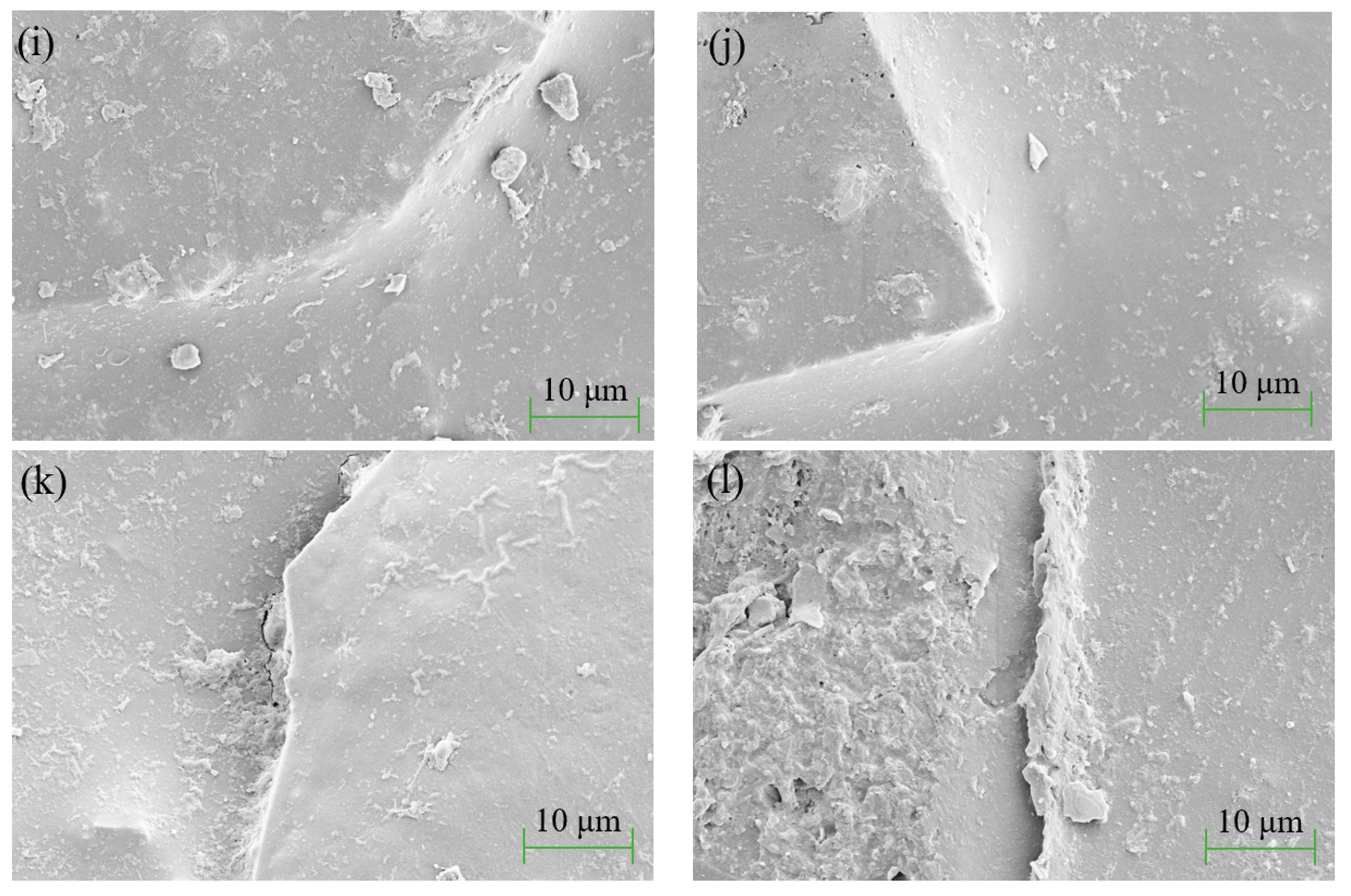
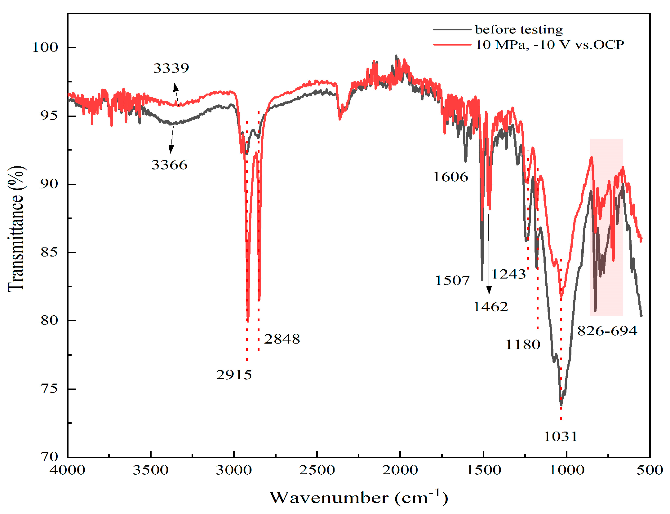
The high hydrostatic pressure and periodic cathodic polarization are effective accelerators which facilitate the diffusion and uptake of water and other corrosive species in the micropores of the coating. This increases the delaminated area rate at the interface between coating and substrate, leading to relatively rapid degradation of the coating. The physical microstructure of the coating is changed under the stresses provided by cathodic polarization and hydrostatic pressure, while the chemical structure of the coating is not affected.

Author Contributions

Conceptualization, L.X.; methodology, L.X., Y.S., Y.L. (Yilong Liu), R.Z., S.B. and X.L.; formal analysis, Y.S. and L.X.; investigation, Y.S.; resources, L.X., Y.L. (Yilong Liu), Y.X., J.H. and F.L.; writing—original draft preparation, Y.S.; writing—review and editing, L.X., Y.L. (Yonghong Lu), H.X. and Y.S.; supervision, L.X., Y.L. (Yonghong Lu) and H.X. All authors have read and agreed to the published version of the manuscript.

Funding

This research was funded by National Key R&D Program of China, grant number 2022YFB3808800.

Institutional Review Board Statement

Not applicable.

Informed Consent Statement

Not applicable.

Data Availability Statement

Not applicable.

Acknowledgments

The authors are grateful for the financial support and permission for publication of this work from National Key R&D Program of China (2022YFB3808800) and Luoyang Ship Material Research Institute.

Conflicts of Interest

The authors declare no conflict of interest.

References

  1. Xu, L.; Xin, Y.; Ma, L.; Zhang, H.; Lin, Z.; Li, X. Challenges and Solutions of Cathodic Protection for Marine Ships. Corros. Commun. 2021, 2, 33–40. [Google Scholar] [CrossRef]
  2. Woloszyk, K.; Garbatov, Y.; Kowalski, J. Experimental Ultimate Strength Assessment of Stiffened Plates Subjected to Marine Immersed Corrosion. Appl. Ocean Res. 2023, 138, 103679. [Google Scholar] [CrossRef]
  3. Bhandari, J.; Khan, F.; Abbassi, R.; Garaniya, V.; Ojeda, R. Modelling of Pitting Corrosion in Marine and Offshore Steel Structures—A Technical Review. J. Loss Prev. Process Ind. 2015, 37, 39–62. [Google Scholar] [CrossRef]
  4. Olajire, A.A. Recent Advances on Organic Coating System Technologies for Corrosion Protection of Offshore Metallic Structures. J. Mol. Liq. 2018, 269, 572–606. [Google Scholar] [CrossRef]
  5. Lyon, S.B.; Bingham, R.; Mills, D.J. Advances in Corrosion Protection by Organic Coatings: What We Know and What We Would like to Know. Prog. Org. Coat. 2017, 102, 2–7. [Google Scholar] [CrossRef]
  6. Buchheit, R.G. Chapter 18—Corrosion Resistant Coatings and Paints. In Handbook of Environmental Degradation of Materials; Kutz, M., Ed.; William Andrew Publishing: Norwich, NY, USA, 2005; pp. 367–385. ISBN 978-0-8155-1500-5. [Google Scholar]
  7. Zhang, F.; Ju, P.; Pan, M.; Zhang, D.; Huang, Y.; Li, G.; Li, X. Self-Healing Mechanisms in Smart Protective Coatings: A Review. Corros. Sci. 2018, 144, 74–88. [Google Scholar] [CrossRef]
  8. MSC.215(82); Performance Standard for Protective Coatings for Dedicated Seawater Ballast Tanks in All Types of Ships and Double-Side Skin Spaces of Bulk Carriers. International Maritime Organization: London, UK, 2006.
  9. Wei, C.; Wang, G.; Cridland, M.; Olson, D.L.; Liu, S. Chapter 25—Corrosion Protection of Ships. In Handbook of Environmental Degradation of Materials, 3rd ed.; Kutz, M., Ed.; William Andrew Publishing: Norwich, NY, USA, 2018; pp. 533–557. ISBN 978-0-323-52472-8. [Google Scholar]
  10. Iannarelli, P.; Beaumont, D.; Liu, Y.; Zhou, X.; Burnett, T.L.; Curioni, M.; Lyon, S.B.; Gibbon, S.R.; Morsh, S.; Emad, S.; et al. The Degradation Mechanism of a Marine Coating under Service Conditions of Water Ballast Tank. Prog. Org. Coat. 2022, 162, 106588. [Google Scholar] [CrossRef]
  11. Oriaifo, E.; Perera, N.; Guy, A.; Leung, P.S.; Tan, K. A Review of Test Protocols for Assessing Coating Performance of Water Ballast Tank Coatings; World Academy of Science, Engineering and Technology: Istanbul, Turkey, 2014; pp. 1610–1615. [Google Scholar]
  12. ISO 20340:2009; Paints and Varnishes—Performance Requirements for Protective Paint Systems for Offshore and Related Structures. ISO: Geneva, Switzerland, 2009.
  13. ISO 12944-9:2018; Paints and Varnishes—Corrosion Protection of Steel Structures by Protective Paint Systems—Part 9: Protective Paint Systems and Laboratory Performance Test Methods for Offshore and Related Structures. ISO: Geneva, Switzerland, 2018.
  14. Lajevardi Esfahani, S.; Ranjbar, Z.; Rastegar, S. Evaluation of Anticorrosion Behavior of Automotive Electrocoating Primers by the AC-DC-AC Accelerated Test Method. Prog. Color Color. Coat. 2013, 7, 187–199. [Google Scholar] [CrossRef]
  15. de Vooys, A.C.A.; Boelen, B.; van der Weijde, D.H. Screening of Coated Metal Packaging Cans Using EIS. Prog. Org. Coat. 2012, 73, 202–210. [Google Scholar] [CrossRef]
  16. Sørensen, P.A.; Kiil, S.; Dam-Johansen, K.; Weinell, C.E. Anticorrosive Coatings: A Review. J. Coat. Technol. Res. 2009, 6, 135–176. [Google Scholar] [CrossRef]
  17. Kotnarowska, D. Influence of Ultraviolet Radiation and Aggressive Media on Epoxy Coating Degradation. Prog. Org. Coat. 1999, 37, 149–159. [Google Scholar] [CrossRef]
  18. García, S.J.; Suay, J. Optimization of Deposition Voltage of Cataphoretic Automotive Primers Assessed by EIS and AC/DC/AC. Prog. Org. Coat. 2009, 66, 306–313. [Google Scholar] [CrossRef]
  19. Deflorian, F.; Rossi, S.; Fedel, M. Organic Coatings Degradation: Comparison between Natural and Artificial Weathering. Corros. Sci. 2008, 50, 2360–2366. [Google Scholar] [CrossRef]
  20. Yu, M.; Fan, C.; Ge, F.; Lu, Q.; Wang, X.; Cui, Z. Anticorrosion Behavior of Organic Offshore Coating Systems in UV, Salt Spray and Low Temperature Alternation Simulated Arctic Offshore Environment. Prog. Org. Coat. 2021, 28, 102545. [Google Scholar] [CrossRef]
  21. ISO 17463:2022; Paints and Varnishes—Guidelines for the Determination of Anticorrosive Properties of Organic Coatings by Accelerated Cyclic Electrochemical Technique. ISO: Geneva, Switzerland, 2022.
  22. Hollaender, J. Rapid Assessment of Food/Package Interactions by Electrochemical Impedance Spectroscopy (EIS). Food Addit. Contam. 1997, 14, 617–626. [Google Scholar] [CrossRef]
  23. Bierwagen, G.; Tallman, D.; Li, J.; He, L.; Jeffcoate, C. EIS Studies of Coated Metals in Accelerated Exposure. Prog. Org. Coat. 2003, 46, 149–158. [Google Scholar] [CrossRef]
  24. Liu, X.; Xiong, J.; Lv, Y.; Zuo, Y. Study on Corrosion Electrochemical Behavior of Several Different Coating Systems by EIS. Prog. Org. Coat. 2009, 64, 497–503. [Google Scholar] [CrossRef]
  25. García, S.J.; Suay, J. A Comparative Study between the Results of Different Electrochemical Techniques (EIS and AC/DC/AC). Prog. Org. Coat. 2007, 59, 251–258. [Google Scholar] [CrossRef]
  26. Usman, B.J.; Scenini, F.; Curioni, M. Exploring the Use of an AC-DC-AC Technique for the Accelerated Evaluation of Anticorrosion Performance of Anodic Films on Aluminium Alloys. Prog. Org. Coat. 2020, 144, 105648. [Google Scholar] [CrossRef]
  27. Gimeno, M.J.; Chamorro, S.; March, R.; Oró, E.; Pérez, P.; Gracenea, J.; Suay, J. Anticorrosive Properties Enhancement by Means of Phosphate Pigments in an Epoxy 2k Coating. Assessment by NSS and ACET. Prog. Org. Coat. 2014, 77, 2024–2030. [Google Scholar] [CrossRef]
  28. Puig, M.; Gimeno, M.J.; Gracenea, J.J.; Suay, J.J. Anticorrosive Properties Enhancement in Powder Coating Duplex Systems by Means of ZMP Anticorrosive Pigment. Assessment by Electrochemical Techniques. Prog. Org. Coat. 2014, 77, 1993–1999. [Google Scholar] [CrossRef]
  29. Abdolah Zadeh, M.; van der Zwaag, S.; García, S.J. Assessment of Healed Scratches in Intrinsic Healing Coatings by AC/DC/AC Accelerated Electrochemical Procedure. Surf. Coat. Technol. 2016, 303, 396–405. [Google Scholar] [CrossRef]
  30. Gimeno, M.J.; Puig, M.; Chamorro, S.; Molina, J.; March, R.; Oró, E.; Pérez, P.; Gracenea, J.J.; Suay, J.J. Improvement of the Anticorrosive Properties of an Alkyd Coating with Zinc Phosphate Pigments Assessed by NSS and ACET. Prog. Org. Coat. 2016, 95, 46–53. [Google Scholar] [CrossRef]
  31. Bethencourt, M.; Botana, F.J.; Cano, M.J.; Osuna, R.M.; Marcos, M. Lifetime Prediction of Waterborne Acrylic Paints with the AC–DC–AC Method. Prog. Org. Coat. 2004, 49, 275–281. [Google Scholar] [CrossRef]
  32. da Silva Lopes, T.; Lopes, T.; Martins, D.; Carneiro, C.; Machado, J.; Mendes, A. Accelerated Aging of Anticorrosive Coatings: Two-Stage Approach to the AC/DC/AC Electrochemical Method. Prog. Org. Coat. 2020, 138, 105365. [Google Scholar] [CrossRef]
  33. Zheng, D.; Gui, Q.; Xu, Y.; Song, G.-L. Modified AC-DC-AC Method for Evaluation of Corrosion Damage of Acrylic Varnish Paint Coating/Q215 Steel System. Prog. Org. Coat. 2021, 159, 106401. [Google Scholar] [CrossRef]
  34. Xu, Y.; Song, G.-L.; Zheng, D.; Feng, Z. The Corrosion Damage of an Organic Coating Accelerated by Different AC-DC-AC Tests. Eng. Fail. Anal. 2021, 126, 105461. [Google Scholar] [CrossRef]
  35. Esfahani, S.L.; Ranjbar, Z.; Rastegar, S. An Electrochemical and Mechanical Approach to the Corrosion Resistance of Cathodic Electrocoatings under Combined Cyclic and DC Polarization Conditions. Prog. Org. Coat. 2014, 77, 1264–1270. [Google Scholar] [CrossRef]
  36. Allahar, K.N.; Bierwagen, G.P.; Gelling, V.J. Understanding Ac–Dc–Ac Accelerated Test Results. Corros. Sci. 2010, 52, 1106–1114. [Google Scholar] [CrossRef]
  37. Kan, B.; Wu, W.; Yang, Z.; Zhang, X.; Li, J. Effects of Hydrostatic Pressure and pH on the Corrosion Behavior of 2205 Duplex Stainless Steel. J. Electroanal. Chem. 2021, 886, 115134. [Google Scholar] [CrossRef]
  38. Yang, Z.X.; Kan, B.; Li, J.X.; Su, Y.J.; Qiao, L.J. Hydrostatic Pressure Effects on Stress Corrosion Cracking of X70 Pipeline Steel in a Simulated Deep-Sea Environment. Int. J. Hydrogen Energy 2017, 42, 27446–27457. [Google Scholar] [CrossRef]
  39. Liu, R.; Cui, Y.; Liu, L.; Zhang, B.; Wang, F. A Primary Study of the Effect of Hydrostatic Pressure on Stress Corrosion Cracking of Ti-6Al-4V Alloy in 3.5% NaCl Solution. Corros. Sci. 2020, 165, 108402. [Google Scholar] [CrossRef]
  40. Liu, R.; Liu, L.; Wang, F. The Role of Hydrostatic Pressure on the Metal Corrosion in Simulated Deep-Sea Environments—A Review. J. Mater. Sci. Technol. 2022, 112, 230–238. [Google Scholar] [CrossRef]
  41. Meng, F.; Liu, L.; Liu, E.; Zheng, H.; Liu, R.; Cui, Y.; Wang, F. Synergistic Effects of Fluid Flow and Hydrostatic Pressure on the Degradation of Epoxy Coating in the Simulated Deep-Sea Environment. Prog. Org. Coat. 2021, 159, 106449. [Google Scholar] [CrossRef]
  42. Peng, W.; Duan, T.; Hou, J.; Guo, X.; Zhang, Y.; Ma, L.; Yu, M.; Xin, Y.; Xing, S.; Zhang, H. Electrochemical Corrosion Behavior of High Strength Steel in Simulated Deep-Sea Environment under Different Hydrostatic Pressure. J. Mater. Res. Technol. 2023, 23, 2301–2316. [Google Scholar] [CrossRef]
  43. Meng, F.; Zhang, T.; Liu, L.; Cui, Y.; Wang, F. Failure Behaviour of an Epoxy Coating with Polyaniline Modified Graphene Oxide under Marine Alternating Hydrostatic Pressure. Surf. Coat. Technol. 2019, 361, 188–195. [Google Scholar] [CrossRef]
  44. Shao, Z.; Ren, P.; Jia, T.; Lei, B.; Feng, Z.; Guo, H.; Chen, S.; Zhang, P.; Meng, G. High-Pressure Induced Acceleration Pathways for Water Diffusion in Heavy Duty Anticorrosion Coatings under Deep Ocean Environment: (I) The Samples Subjected to High-Pressure Pre-Processing. Prog. Org. Coat. 2022, 170, 106948. [Google Scholar] [CrossRef]
  45. Liu, Y.; Wang, J.; Liu, L.; Li, Y.; Wang, F. Study of the Failure Mechanism of an Epoxy Coating System under High Hydrostatic Pressure. Corros. Sci. 2013, 74, 59–70. [Google Scholar] [CrossRef]
  46. Dong, J.-J.; Fan, L.; Zhang, H.-B.; Xu, L.-K.; Xue, L.-L. Electrochemical Performance of Passive Film Formed on Ti–Al–Nb–Zr Alloy in Simulated Deep Sea Environments. Acta Metall. Sin. Engl. Lett. 2020, 33, 595–604. [Google Scholar] [CrossRef]
  47. ISO-5668:2023; Corrosion of Metals and Alloys Guidelines and Requirements for Corrosion Testing in Simulated Environment of Deep-Sea Water. ISO: Geneva, Switzerland, 2023.
  48. Corfias, C.; Pébère, N.; Lacabanne, C. Characterization of Protective Coatings by Electrochemical Impedance Spectroscopy and a Thermostimulated Current Method: Influence of the Polymer Binder. Corros. Sci. 2000, 42, 1337–1350. [Google Scholar] [CrossRef]
  49. Liu, J.; Lu, Z.; Zhang, L.; Li, C.; Ding, R.; Zhao, X.; Zhang, P.; Wang, B.; Cui, H. Studies of Corrosion Behaviors of a Carbon Steel/Copper-Nickel Alloy Couple under Epoxy Coating with Artificial Defect in 3.5 wt.% NaCl Solution Using the WBE and EIS Techniques. Prog. Org. Coat. 2020, 148, 105909. [Google Scholar] [CrossRef]
  50. Trentin, A.; Pakseresht, A.; Duran, A.; Castro, Y.; Galusek, D. Electrochemical Characterization of Polymeric Coatings for Corrosion Protection: A Review of Advances and Perspectives. Polymers 2022, 14, 2306. [Google Scholar] [CrossRef] [PubMed]
  51. Shi, C.; Shao, Y.; Wang, Y.; Meng, G.; Liu, B. Influence of Submicro-Sheet Zinc Phosphate Modified by Urea-Formaldehyde on the Corrosion Protection of Epoxy Coating. Surf. Interfaces 2020, 18, 100403. [Google Scholar] [CrossRef]
  52. Zhang, Y.; Shao, Y.; Liu, X.; Shi, C.; Wang, Y.; Meng, G.; Zeng, X.; Yang, Y. A Study on Corrosion Protection of Different Polyaniline Coatings for Mild Steel. Prog. Org. Coat. 2017, 111, 240–247. [Google Scholar] [CrossRef]
  53. Ganborena, L.; Vega, J.M.; Özkaya, B.; Grande, H.-J.; García-Lecina, E. AN SKP and EIS Study of Microporous Nickel-Chromium Coatings in Copper Containing Electrolytes. Electrochimica Acta 2019, 318, 683–694. [Google Scholar] [CrossRef]
  54. Monetta, T.; Bellucci, F.; Nicodemo, L.; Nicolais, L. Protective Properties of Epoxy-Based Organic Coatings on Mild Steel. Prog. Org. Coat. 1993, 21, 353–369. [Google Scholar] [CrossRef]
  55. Del Grosso Destreri, M.; Vogelsang, J.; Fedrizzi, L.; Deflorian, F. Water Up-Take Evaluation of New Waterborne and High Solid Epoxy Coatings. Part II: Electrochemical Impedance Spectroscopy. Prog. Org. Coat. 1999, 37, 69–81. [Google Scholar] [CrossRef]
  56. Del Grosso Destreri, M.; Vogelsang, J.; Fedrizzi, L. Water Up-Take Evaluation of New Waterborne and High Solid Epoxy Coatings. Prog. Org. Coat. 1999, 37, 57–67. [Google Scholar] [CrossRef]
  57. Loveday, D.; Peterson, P.; Rodgers, B. Evaluation of Organic Coatings with Electrochemical Impedance Spectroscopy. JCT Coat. Tech. 2004, 8, 46–52. [Google Scholar]
  58. Lashgari, S.M.; Yari, H.; Mahdavian, M.; Ramezanzadeh, B.; Bahlakeh, G.; Ramezanzadeh, M. Application of Nanoporous Cobalt-Based ZIF-67 Metal-Organic Framework (MOF) for Construction of an Epoxy-Composite Coating with Superior Anti-Corrosion Properties. Corros. Sci. 2021, 178, 109099. [Google Scholar] [CrossRef]
  59. Brasher, D.M.; Kingsbury, A.H. Electrical Measurements in the Study of Immersed Paint Coatings on Metal. I. Comparison between Capacitance and Gravimetric Methods of Estimating Water-Uptake. J. Appl. Chem. 1954, 4, 62–72. [Google Scholar] [CrossRef]
  60. Miszczyk, A.; Darowicki, K. Water Uptake in Protective Organic Coatings and Its Reflection in Measured Coating Impedance. Prog. Org. Coat. 2018, 124, 296–302. [Google Scholar] [CrossRef]
  61. Fan, C.; Shi, J.; Dilger, K. Water Uptake and Interfacial Delamination of an Epoxy-Coated Galvanized Steel: An Electrochemical Impedance Spectroscopic Study. Prog. Org. Coat. 2019, 137, 105333. [Google Scholar] [CrossRef]
  62. Liu, R.; Liu, L.; Meng, F.; Tian, W.; Liu, Y.; Li, Y.; Wang, F. Finite Element Analysis of the Water Diffusion Behaviour in Pigmented Epoxy Coatings under Alternating Hydrostatic Pressure. Prog. Org. Coat. 2018, 123, 168–175. [Google Scholar] [CrossRef]
  63. Mansfeld, F. Use of Electrochemical Impedance Spectroscopy for the Study of Corrosion Protection by Polymer Coatings. J. Appl. Electrochem. 1995, 25, 187–202. [Google Scholar] [CrossRef]
  64. Liu, J.; Xiang-Bo, L.; Jia, W.; Tian-Yuan, L.; Xiao-Ming, W. Studies of Impedance Models and Water Transport Behaviours of Epoxy Coating at Hydrostatic Pressure of Seawater. Prog. Org. Coat. 2013, 76, 1075–1081. [Google Scholar] [CrossRef]
  65. Fadl, A.M.; Abdou, M.I.; Hamza, M.A.; Sadeek, S.A. Corrosion-Inhibiting, Self-Healing, Mechanical-Resistant, Chemically and UV Stable PDMAS/TiO2 Epoxy Hybrid Nanocomposite Coating for Steel Petroleum Tanker Trucks. Prog. Org. Coat. 2020, 146, 105715. [Google Scholar] [CrossRef]
  66. Contu, F.; Fenzy, L.; Taylor, S.R. An FT-IR Investigation of Epoxy Coatings as a Function of Electrolyte Composition. Prog. Org. Coat. 2012, 75, 92–96. [Google Scholar] [CrossRef]
  67. Bajat, J.B.; Milošev, I.; Jovanović, Ž.; Mišković-Stanković, V.B. Studies on Adhesion Characteristics and Corrosion Behaviour of Vinyltriethoxysilane/Epoxy Coating Protective System on Aluminium. Appl. Surf. Sci. 2010, 256, 3508–3517. [Google Scholar] [CrossRef]
  68. Jaisai, M.; Baruah, S.; Dutta, J. Paper Modified with ZnO Nanorods—Antimicrobial Studies. Beilstein J. Nanotechnol. 2012, 3, 684–691. [Google Scholar] [CrossRef]
  69. Meng, F.; Liu, L.; Tian, W.; Wu, H.; Li, Y.; Zhang, T.; Wang, F. The Influence of the Chemically Bonded Interface between Fillers and Binder on the Failure Behaviour of an Epoxy Coating under Marine Alternating Hydrostatic Pressure. Corros. Sci. 2015, 101, 139–154. [Google Scholar] [CrossRef]
  70. Tian, W.; Meng, F.; Liu, L.; Li, Y.; Wang, F. The Failure Behaviour of a Commercial Highly Pigmented Epoxy Coating under Marine Alternating Hydrostatic Pressure. Prog. Org. Coat. 2015, 82, 101–112. [Google Scholar] [CrossRef]
  71. Tian, W.; Liu, L.; Meng, F.; Liu, Y.; Li, Y.; Wang, F. The Failure Behaviour of an Epoxy Glass Flake Coating/Steel System under Marine Alternating Hydrostatic Pressure. Corros. Sci. 2014, 86, 81–92. [Google Scholar] [CrossRef]
  72. Hongyang GAO, W.W. Degradation Behavior of a Modified Epoxy Coating in Simulated Deep-Sea Environment. J. Chin. Soc. Corros. Prot. 2017, 37, 247–263. [Google Scholar] [CrossRef]
  73. Liu, L.; Cui, Y.; Li, Y.; Zhang, T.; Wang, F. Failure Behavior of Nano-SiO2 Fillers Epoxy Coating under Hydrostatic Pressure. Electrochimica Acta 2012, 62, 42–50. [Google Scholar] [CrossRef]
  74. Zhang, X.; Wu, W.; Li, Y.; Li, J.; Qiao, L. Corrosion Form Transition of Mooring Chain in Simulated Deep-Sea Environments: Remarkable Roles of Dissolved Oxygen and Hydrostatic Pressure. J. Mater. Sci. Technol. 2023, 162, 118–130. [Google Scholar] [CrossRef]
Figure 1. EIS spectra of the glass flake epoxy coating sample recorded at different immersion time in seawater under atmospheric pressure. (a) Nyquist plots; (b) Bode plots.
Coatings 13 01843 g001
Figure 2. Equivalent circuit model used for EIS fitting of the coated sample immersed in seawater.
Coatings 13 01843 g002
Figure 3. The impedance modulus at low-frequency (f = 0.01 Hz) and coating resistance (a) and coating capacitance (b) of the coated steel sample in seawater at different immersion times under atmospheric pressure.
Coatings 13 01843 g003
Figure 4. Electrochemical impedance spectra of the glass flake epoxy coating sample recorded in seawater at different cycles of AC-DC-AC test under atmospheric pressure. (a) Nyquist plots; (b) Bode plots.
Coatings 13 01843 g004
Figure 5. Electrochemical impedance spectra of the glass flake epoxy coating sample recorded in seawater at different cycles of AC-DC-AC test under 10 MPa hydrostatic pressure. (a) Nyquist plots; (b) Bode plots.
Coatings 13 01843 g005
Figure 6. Variation of impedance modulus at a low frequency (f = 0.01 Hz) of the glass flake epoxy coating with time under different testing conditions.
Coatings 13 01843 g006
Figure 7. Variation of coating resistance Rc of the glass flake epoxy coating with time under different testing conditions.
Coatings 13 01843 g007
Figure 8. (a) Variation curve of water uptake of the glass flake epoxy coating with immersion time in seawater under different testing conditions; (b) linear fitting of the glass flake epoxy coating with immersion time in seawater under different testing conditions.
Coatings 13 01843 g008
Figure 9. Variation of breakpoint frequency fb of the glass flake epoxy coating with immersion time in seawater under different testing conditions.
Coatings 13 01843 g009
Figure 10. The macroscopic photographs (ad), optical microscopic images (eh), and SEM microscopic morphologies (il) of the coated samples before and after testing for 240 h in three environments. (a,e,i) The as-prepared coating sample before testing; (b,f,j) after the usual immersion test in seawater; (c,g,k) after the AC-DC-AC test at atmospheric pressure; (d,h,l) and after the AC-DC-AC test coupled with hydrostatic pressure.
Coatings 13 01843 g010aCoatings 13 01843 g010b
Figure 11. FT-IR spectra of the glass flake epoxy coating sample before testing and after the AC-DC-AC test under 10 MPa hydrostatic pressure in for 240 h.
Coatings 13 01843 g011
Table 1. The fitting results of EIS data of specimens under different testing conditions.
Testing ConditionsFitting Parameters1 h24 h72 h120 h192 h240 h
Immersion in seawater at atmospheric pressureRs
(Ω·cm2)
0.610.310.540.410.210.11
Rc
(Ω·cm2)
1.98
×1010
1.73
×1010
1.67
×1010
1.66
×1010
1.65
×1010
1.63
×1010
Qc
(F/cm2)
2.46
×10−10
2.58
×10−10
2.69
×10−10
2.70
×10−10
2.79
×10−10
2.84
×10−10
n0.950.960.960.950.950.95
AC-DC-AC cycling at atmospheric pressureRs
(Ω·cm2)
1.721.901.841.651.551.32
Rc
(Ω·cm2)
1.05
×1010
6.77
×109
5.47
×109
5.03
×109
3.77
×109
3.47
×109
Qc
(F/cm2)
1.76
×10−10
1.88
×10−10
1.89
×10−10
1.91
×10−10
1.97
×10−10
2.04
×10−10
n0.930.940.960.950.930.95
AC-DC-AC coupled with hydrostatic pressureRs
(Ω·cm2)
0.730.810.910.800.840.72
Rc
(Ω·cm2)
1.47
×1010
2.60
×109
1.73
×109
1.49
×109
1.04
×109
9.92
×108
Qc
(F/cm2)
1.19
×10−10
1.44
×10−10
1.50
×10−10
1.57
×10−10
1.58
×10−10
1.72
×10−10
n0.960.950.940.950.950.94
Table 2. Delaminated area (Ad) and delaminated area ratio (α) of the glass flake epoxy coating after testing for 240 h under different conditions.
Testing ConditionsAd (cm2)α
Immersion in seawater at atmospheric pressure2.981 × 10−64.217 × 10⁻⁷
AC-DC-AC cycling at atmospheric pressure2.642 × 10−53.738 × 10⁻⁶
AC-DC-AC coupled with hydrostatic pressure1.272 × 10−41.800 × 10⁻⁵
Disclaimer/Publisher’s Note: The statements, opinions and data contained in all publications are solely those of the individual author(s) and contributor(s) and not of MDPI and/or the editor(s). MDPI and/or the editor(s) disclaim responsibility for any injury to people or property resulting from any ideas, methods, instructions or products referred to in the content.

