Abstract
AlTiN nitride coatings on the surfaces of metal-working tools can greatly extend their service life. The coatings are deposited from plasma flows generated by vacuum arc burning on the cathode surface. The elemental and charge composition of the plasma flows, as well as the content of metal drops, depend on the cathode’s structure. In this paper, the microstructure, elemental, and phase compositions of the surface layer of Al-Ti cathodes subjected to vacuum arc heating were studied. These cathodes had similar elemental compositions (Ti + 50 at.% Al) but differed from one another in their phase composition and microstructure (grain size, porosity). The cathodes were studied by X-ray diffraction analysis, scanning electron microscopy, and electron probe analysis. It was found that during vacuum arc heating, surface fusion or thermal cracking of the cathode’s surface layer occurs. The thickness, structure, and phase composition of the modified layer were controlled by the thermal conductivity of the cathode material, which, in turn, depended on the phase composition and porosity of the cathodes. The maximum thickness of the modified layer (up to 400 µm) was observed on the surface of the sintered cathode due to the lower thermal conductivity of the porous structure of the cathode. The obtained results can be used for the development of coating deposition technology based on vacuum arc sputtering of multicomponent cathodes.
1. Introduction
Vacuum arc evaporation of metal and metallic alloy cathodes in reactive gas media is widely used for the deposition of wear-resistant coatings on the surfaces of metal-working tools [1,2,3]. The surface of the cathodes, used for the coating’s deposition by vacuum arc evaporation, is heated to high temperatures exceeding the melting point of the cathode material. Surface melting leads to an increased content of drops in the products of the arc erosion, and the lower the melting temperature of the cathode, the greater the number of droplets [4,5]. Heating of the surface layer of the composite cathodes produced by forging a mechanical mixture of elemental powders is accompanied by structural and phase transformations [6,7]. The duration of the reactions between the powder components in the mixture depends on the dispersity of the powders [7,8]. As a result, the mechanical mixtures of elemental powders turn into refractory compounds [9,10]. The heating rate of the cathode, along with the magnitude of the current, depends on the thermal conductivity of the cathode material, which, in turn, is determined by the phase composition and structure. The thickness of the modified layer of the cathode depends on two factors: thermal conductivity and melting temperature. As a rule, the thermal conductivity of the intermetallic compounds is less than that of metals. Thus, the surface temperature of an intermetallic cathode of similar elemental composition is expected to be higher than that of a composite cathode represented by a powder mixture. On the other hand, due to the higher melting point of metal aluminides compared to the low melting point of aluminum in composite cathodes, the thickness of the melted surface layer on composite cathodes can be thicker than that on aluminide cathodes. Due to the high hardness, poor plasticity, and low thermal conductivity of the intermetallic compounds, thermal stress cracks emerge on the surface layer of the intermetallic cathode [10]. The thermal cracking leads to the spalling of the modified layer and an enhancement in the rate of the cathode erosion [10].
The physical properties of the cathode’s material influence the emission rate, charge, and elemental composition of the ejected plasma flows. In [11,12,13], a correlation was found between the cohesive energy of the cathode material, the combustion voltage, and plasma parameters. The influence of the structure and composition of the cathode on the drop ejection, charge, and energy of ions were studied and discussed in [14,15,16,17,18,19]. The structure state of the cathode’s surface layer that was subjected to vacuum arc heating depends on both the elemental composition and pressure of the gaseous media in the technological chamber. A redeposition of the ejected drops on the cathode surface occurs under elevated gas pressure [20]. Another effect related to the gaseous media is the poisoning of the cathode surface as a result of interaction with the reactive gases [21,22].
TiAlN coatings deposited from vacuum arc plasma in a nitrogen environment remain the most popular among wear-resistant coatings for metal-working tools due to their high durability [23,24,25]. To enhance the properties of TiAlN coatings, cathodes of different designs are used: mosaic [26], composite [6,26], or cast [6]. The study of the phase composition of the surface layer of composite and Ti-50 at.% Al-cast cathodes were subjected to vacuum arc treatment in [6] using the X-ray diffraction method. According to X-ray diffraction patterns, the ratio of Ti3Al, TiAl, Ti2Al5, and TiAl3 aluminides in the surface layer of both cathodes depends on the distance of the analyzed spot from the center of the round cathode. Ti3Al and TiAl aluminides have melting points of 1475 °C and 1447 °C, respectively, which are higher than the melting point of aluminum (660 °C), which is the basis of the powder composite cathode. In the present work, comparative studies of the surface layer of Al-Ti cathodes modified by a vacuum arc were fulfilled. The cathodes have the same elemental composition but differ in phase composition. Contrary to [6], we studied the cross-section of the modified layer. The research results can be useful in the development of advanced industrial technologies for the production of metal-working tools with high durability.
2. Materials and Experimental Technique
Four cathodes of similar compositions (Ti + 50 at.% Al) obtained by different technologies (Table 1) were analyzed. Since the production technology of commercial cathodes is not disclosed by producing companies, the cathode production technology was determined based on the results of microstructural studies (Table 1). The sintered cathode was obtained by mixing titanium powders (fraction less than 125 μm) and TiAl3 intermetallic compound (fraction less than 50 μm), pressing under a pressure of 0.3 GPa, vacuum sintering at 1250 °C and isothermal holding for 4 h.

Table 1.
Supplier and production technology of the Ti-Al cathodes.
The starting phase composition of the cathodes was studied on its back surface layer, which was not exposed to the vacuum arc. The working surfaces of cathodes with a diameter of 70 mm were treated for 60 min with an arc current of 90 A in N2 gas under a pressure of 0.065 Pa. Structural studies of the cathodes were carried out using X-ray diffraction (XRD) (Co Kα radiation, DRON-7, St. Petersburg, Russia) and scanning electron microscopy (LEO EVO 50, Oberkochen, Germany). ASTM data files and PDWin 4.00 software were used for phase identification and characterization. The elemental composition of the modified layer was determined by X-ray spectroscopy (EDS). The microstructure and phase composition of the cathodes were studied on cross-sections polished and etched with Keller’s reagent (2.5 mL HNO3 + 1.5 mL HCl + 1 mL HF + 95 mL H2O). The microhardness of the samples was measured on etched sections using a PMT-3 microhardness tester under a load of 0.98 N.
3. Results
3.1. Starting Structural State of Cathodes
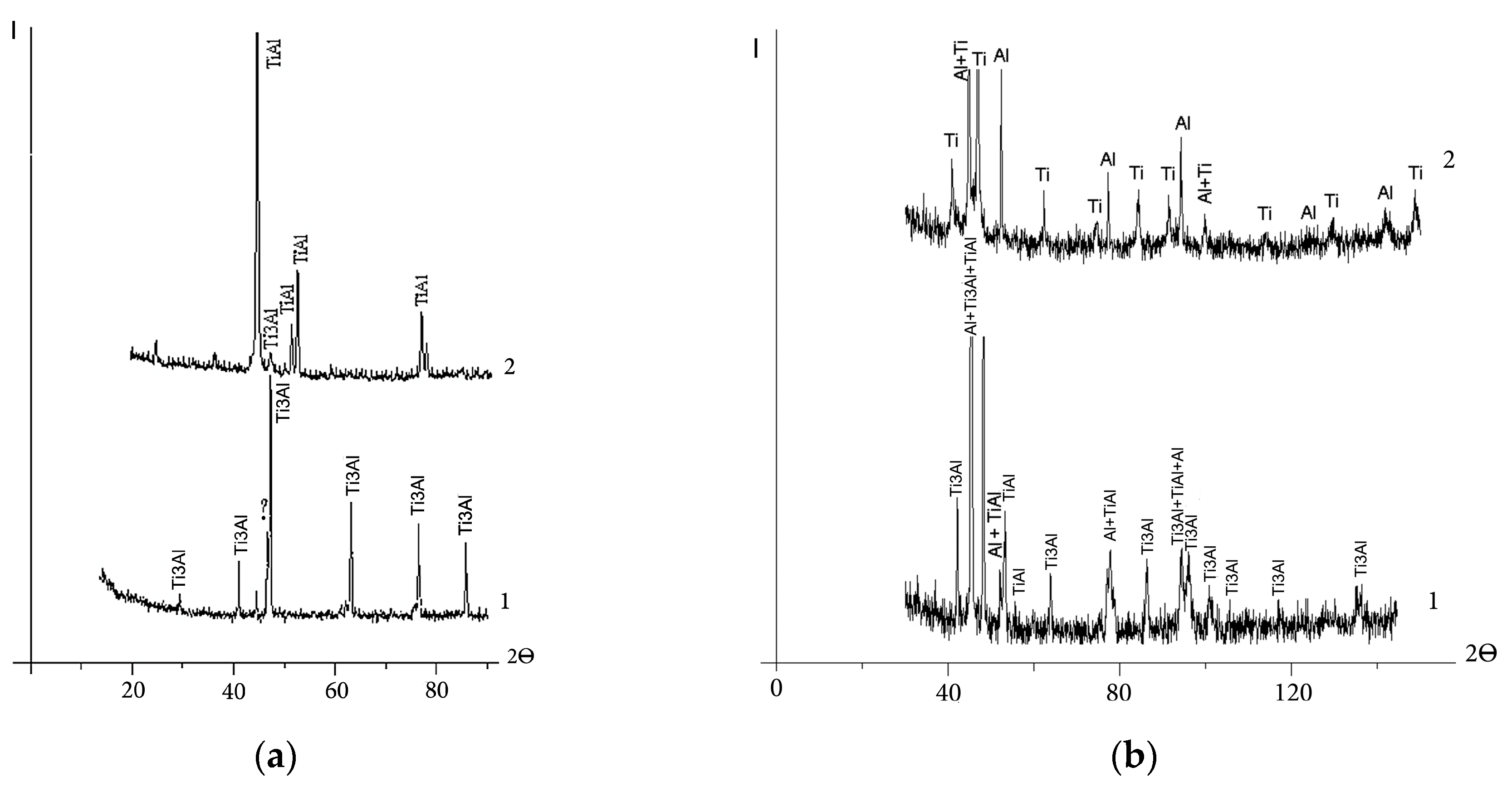
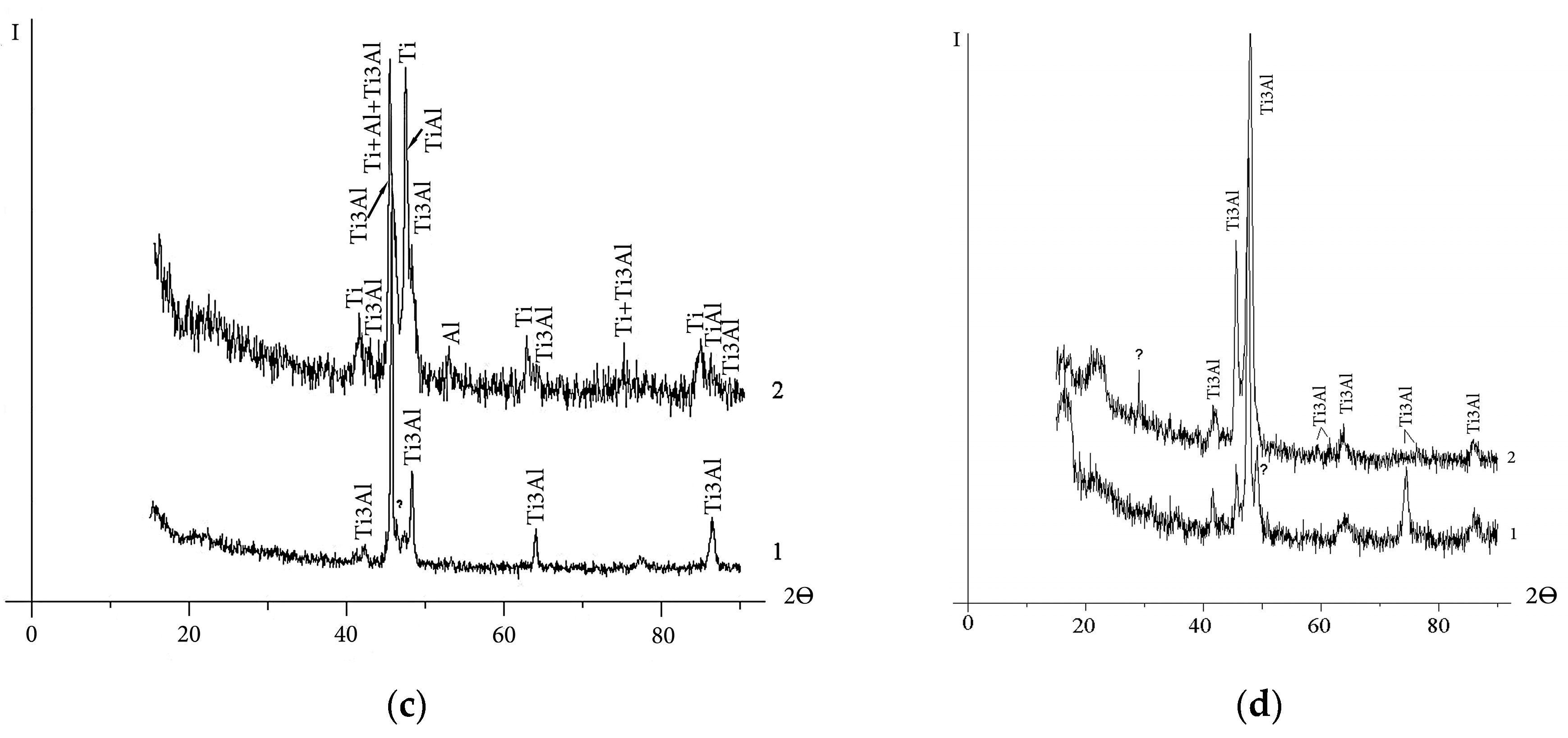
The X-ray patterns of the back surface layer of the cathodes in the starting structural state and from the working surface exposed to the vacuum arc are shown in Figure 1. Table 2 presents the phase composition of the cathodes, estimated from the sum of the intensities of X-ray reflections by the processing of X-ray diffraction patterns (Figure 1). Due to the superposition of lines of different phases as well as due to the high background level, this method does not allow us to determine the exact content of the constituents. However, according to the data in Table 2, the sintered cathode in the starting state consists mainly of the Ti3Al phase and a small amount of the γ-TiAl intermetallic compound. Hot-pressed cathode No. 2 consists almost entirely of Ti and Al. In addition to Ti and Al, there are intermetallic compounds TiAl and Ti3Al in the structure of hot-pressed cathode No. 3. The cast cathode consists almost entirely of the Ti3Al intermetallic compound.
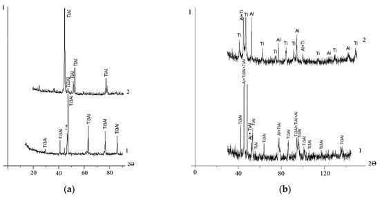

Figure 1.
X-ray diffraction patterns of the cathodes: arc exposed surface layer (1) and back surface layer (2): (a) sintered, No. 1; (b) “Polema”, No. 2; (c) “Umicore”, No. 3; (d) cast, No. 4. Symbol «?»—unidentified phases.
Table 2.
X-ray diffraction analysis of phase composition of cathodes.
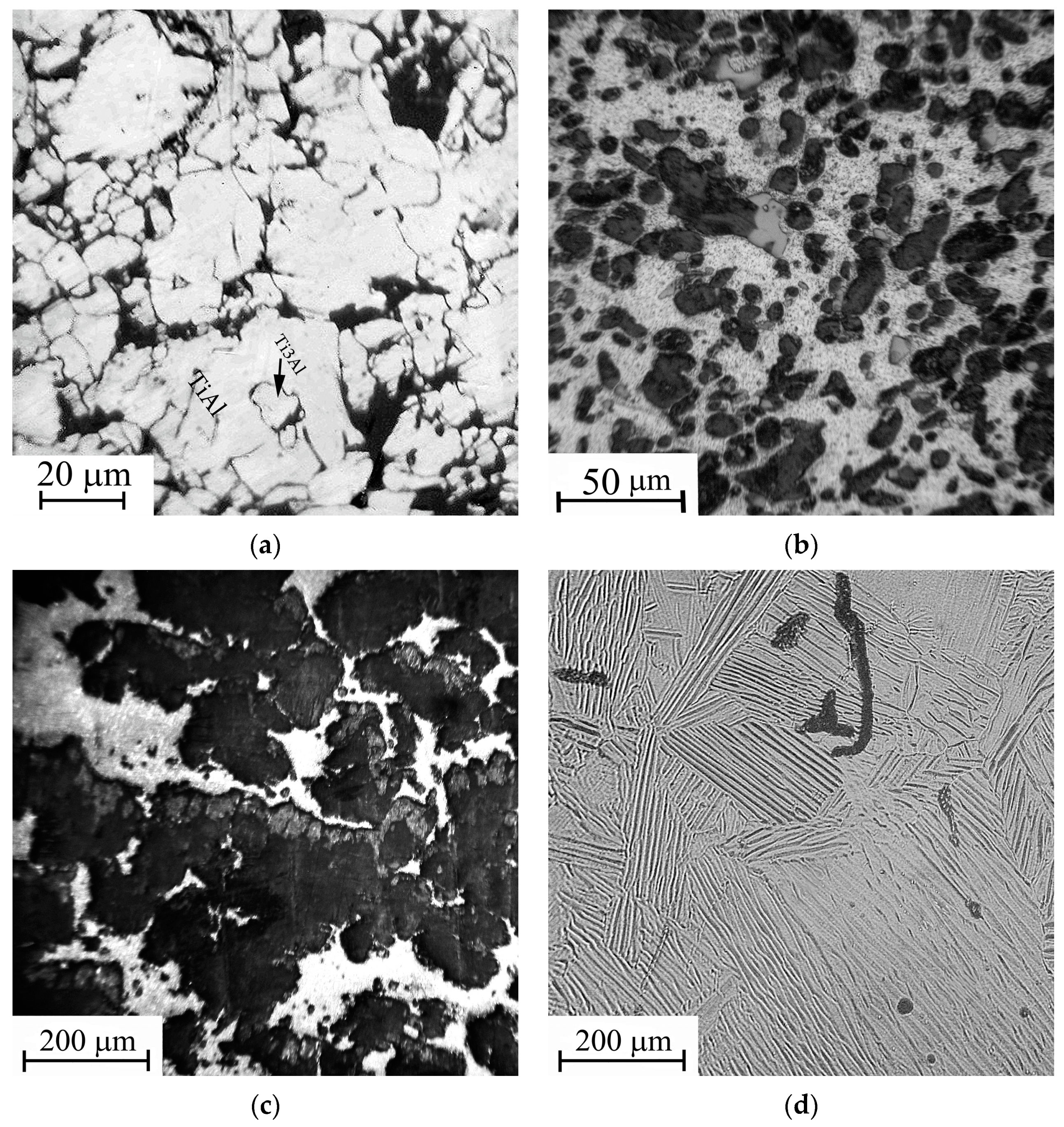
The results of the X-ray phase analysis are in accordance with the data of optical metallography of the cathode material in the starting state (Figure 2). In the etched section of the sintered cathode (Figure 2a), two constituents are presented. According to structural studies [27], a ring structure is formed as a result of the sintering of powder mixtures of Ti and TiAl3 intermetallic compounds, which have an integral elemental composition close to TiAl. The ring structure consists of Ti3Al aluminide in the peripheral part and a compound of TiAl3 inclusions. With the increasing duration of isothermal sintering, the width of the rings increases. Accordingly, the volume fraction of Ti3Al also increases. This two-phase ring structure is especially seen in backscattered electron images (Figure 3a). In the cathode structure sintered at 1250 °C for 4 h, the Ti3Al phase occurs in the form of several inclusions inside TiAl grains (Figure 2a). The TiAl3 phase after vacuum sintering and isothermal holding is completely consumed in the reaction TiAl3 + Ti → TiAl (Ti3Al). The relatively low content of the Ti3Al phase in the sintered cathode is confirmed via calculations based on the sum of the intensities of X-ray reflections (Figure 1a, Table 2).

Figure 2.
Starting microstructure of Ti-Al cathodes (back surface layer): (a) sintered, No. 1; (b) “Polema”, No. 2; (c) “Umicore”, No. 3; (d) cast, No. 4. (Optical metallography, etching with Keller’s reagent).

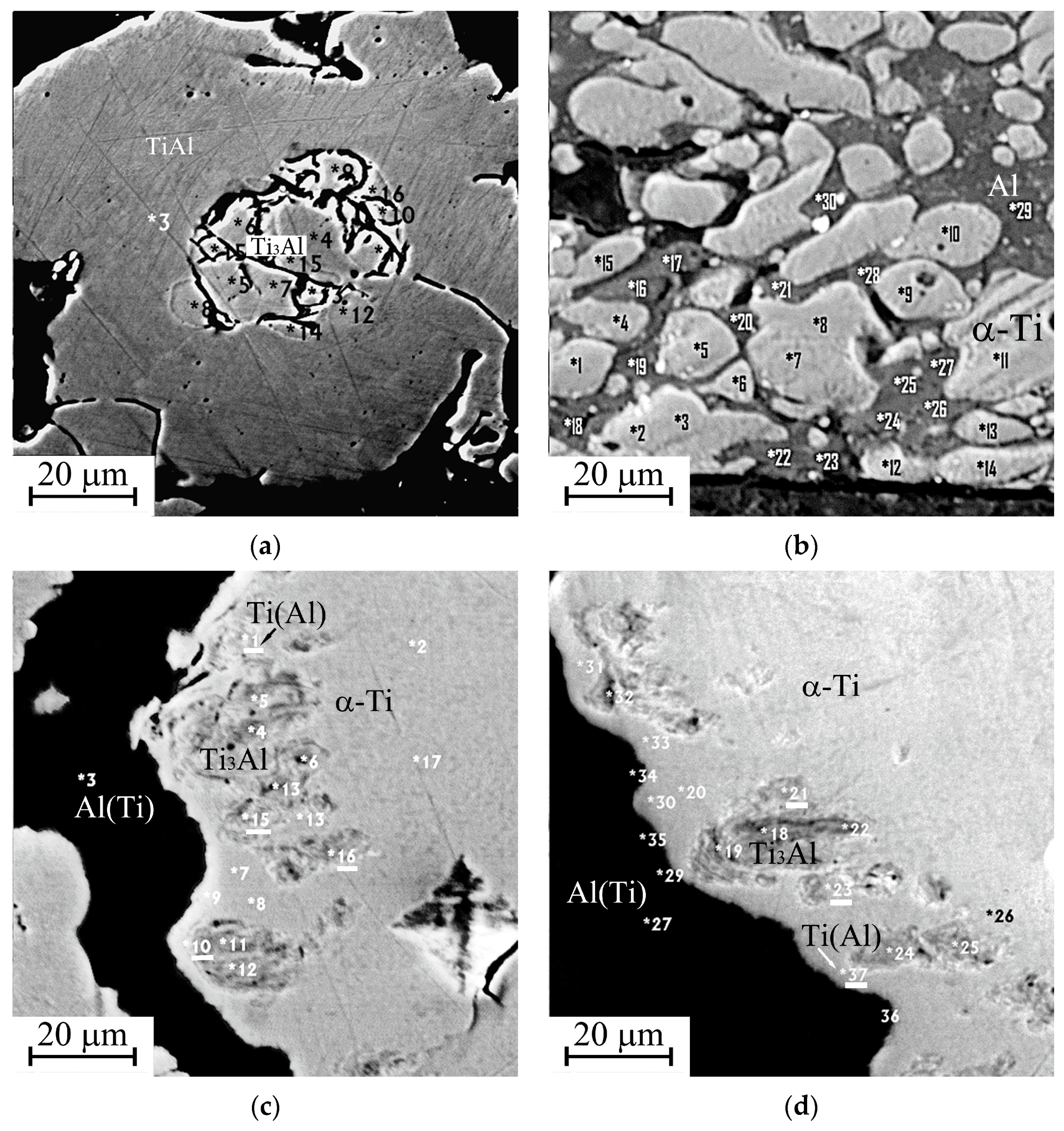
Figure 3.
Starting microstructure of the cathodes in backscattered electrons: (a) sintered, No. 1; (b) “Polema”, No. 2; (c,d) “Umicore”, No. 3. Spots of local elemental analysis are indicated with the numbers (Table 3).
The microstructure of the “Umicore” and “Polema” hot-pressed cathodes (Figure 2b,c) indicates the presence of structurally isolated pure elements—Al (light phase) and Ti (dark gray phase). However, hot-pressed cathodes from these two suppliers differ significantly in microstructure and phase composition. The “Umicore” cathode (Figure 2c) has a coarser structure. The size of the Ti particles (105 ± 46 µm) is nearly an order of magnitude larger than in the “Polema” cathode (12.2 ± 6.0 µm). In addition, intermetallic interlayers are clearly seen at the interphase boundaries of titanium and aluminum in the “Umicore” cathode. According to the X-ray diffraction data (Table 2), this cathode contains 30%–40% intermetallic phases. In the “Polema” cathode, the content of Ti3Al is only 2%, and there are no intermetallic interlayers at the boundaries. The cast cathode has a lamellar structure typical of a titanium alloy, with rare defects in the form of pores and non-metallic inclusions (Figure 2d).
More detailed information about the starting structure of cathode materials was obtained by studying backscattered electron images (Figure 3). In contrast to the optical micrographs in Figure 2b,c, titanium grains appear as lighter areas against the background of a dark aluminum matrix in the backscattered electron images. Accordingly, the grains of intermetallic compounds of the Ti-Al system in the images get darker as the amount of aluminum they contain increases.
The elemental composition of the phases presented in the sintered cathode corresponds to the results of X-ray diffraction analysis. Local analysis of the aluminum matrix of the “Polema” cathode disclosed the titanium content up to 3.6 at.% compared to approximately an order of magnitude lower equilibrium solubility of Ti in solid aluminum [28]. This discrepancy most likely has methodological reasons. One of the possible reasons is associated with the insufficiently small size of the electron probe for the dispersed structure of the “Polema” cathode, as well as with the possible presence of titanium grains in the analyzed subsurface layer. The validity of this explanation is confirmed by local analysis data. The content of Ti in the aluminum matrix of the “Umicore” cathode with a coarse structure is almost three times less than that in the “Polema” cathode (Table 3). The differences in the microhardness of aluminum in the “Polema” and “Umicore” cathodes are also associated with different dispersities of the mechanical mixture of Ti and Al (Table 3).
Table 3.
Starting elemental composition of the cathodes.
Electron-backscattered images of the cross-section of the “Umicore” cathode (Figure 3) present large titanium particles within the black color aluminum matrix. Single Ti3Al inclusions occur in Ti particles near the boundary with the aluminum matrix. In some areas of the boundaries of intermetallic inclusions, the local elemental analysis reveals interlayers of aluminum solid solution in titanium. In the areas selected for local analysis, the Ti3Al compound present in the starting cathode according to X-ray diffraction analysis was not detected. This is an additional confirmation of the strong homogeneity of the cathode structure, which is presented in Figure 2c.
3.2. Structural-Phase State of Arc Modified Surface Layer of the Cathodes
The results of X-ray diffraction analysis of a thin (up to 10 μm) layer adjacent to the working surface of the cathodes (Figure 1) are shown in Table 2. The data on the elemental composition of the modified layer and phase composition obtained based on EDS microanalysis are presented in Table 3, Table 4 and Table 5 along with the hardness of the structure constituents.
Table 4.
Results of elemental analysis of the modified surface layer sintered cathode.
Table 5.
Results of elemental analysis of the modified surface layer “Polema” cathode.
3.2.1. Cast Cathode No. 4
The cracks of a length up to 500 μm are found in zone 2, adjacent to the cathode’s surface layer (zone 1), subjected to arc treatment (Figure 4). The crack density and crack tip opening displacement decrease with distance from the cathode’s surface layer. The most probable reason for the surface cracking is a temperature gradient resulting in the thermal stress. A thin layer is seen adjacent to the working surface. The layer has a thickness of 20–50 µm and, according to X-ray diffraction data, mainly consists of Ti3Al. Along with Ti3Al, there is a small amount of TiH0.71 hydride. The appearance of a hydride may be associated with the presence of hydrocarbon and, possibly, water molecules in the vacuum chamber. No other phases were found in the modified layer. Since the thin surface layer is separated from the multitracked zone by a sharp boundary, it can be argued that it was formed as a result of the crystallization of a thin melt film on the working surface of the cathode.
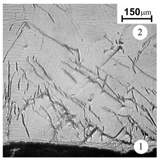
Figure 4.
The microstructure of the cast cathode near the surface layer subjected to the arc treatment (optical metallography, etching Keller’s reagent). 1—arc exposed layer; 2—back surface layer.
3.2.2. Sintered Cathode No. 1
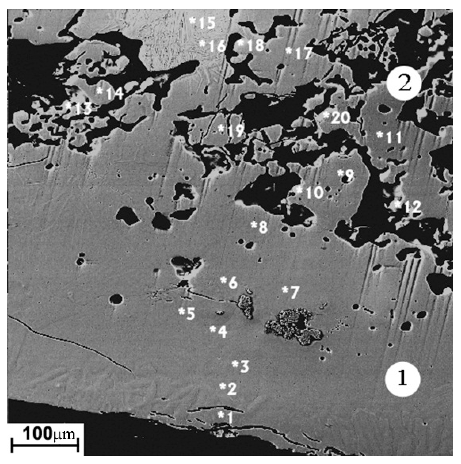
The modified layer on the sintered cathode (Figure 5, zone 1) has of the greatest thickness (250–400 µm). The porosity of the layer is minimal, in contrast to the starting material, which has high porosity in the form of dark areas in the carcass structure, corresponding to the two-phase Ti3Al + TiAl region on the equilibrium diagram (Figure 5, zone 2). The occasional cracks are directed mainly in parallel with the cathode surface. The average elemental composition of the layer corresponds to the Ti3Al phase. The structure of the modified layer is apparently formed during the crystallization of the melted layer on the cathode surface. The main reason for the great thickness of the melted layer is the low thermal conductivity with the high cathode porosity. Due to the thermal effects, the phase composition and structure of the cathode material adjacent to the modified layer differ from the original one (Figure 3a). The thickness of the melted layer on the surface of the porous sintered cathode is several times greater than that of the melted layer on the surface of the non-porous cast cathode.

Figure 5.
The image of the sintered cathode modified layer in backscattered electrons. 1—arc exposed layer; 2—adjacent zone. Spots of local elemental analysis are indicated with the numbers (Table 4).
3.2.3. Cathode No. 2, “Polema”
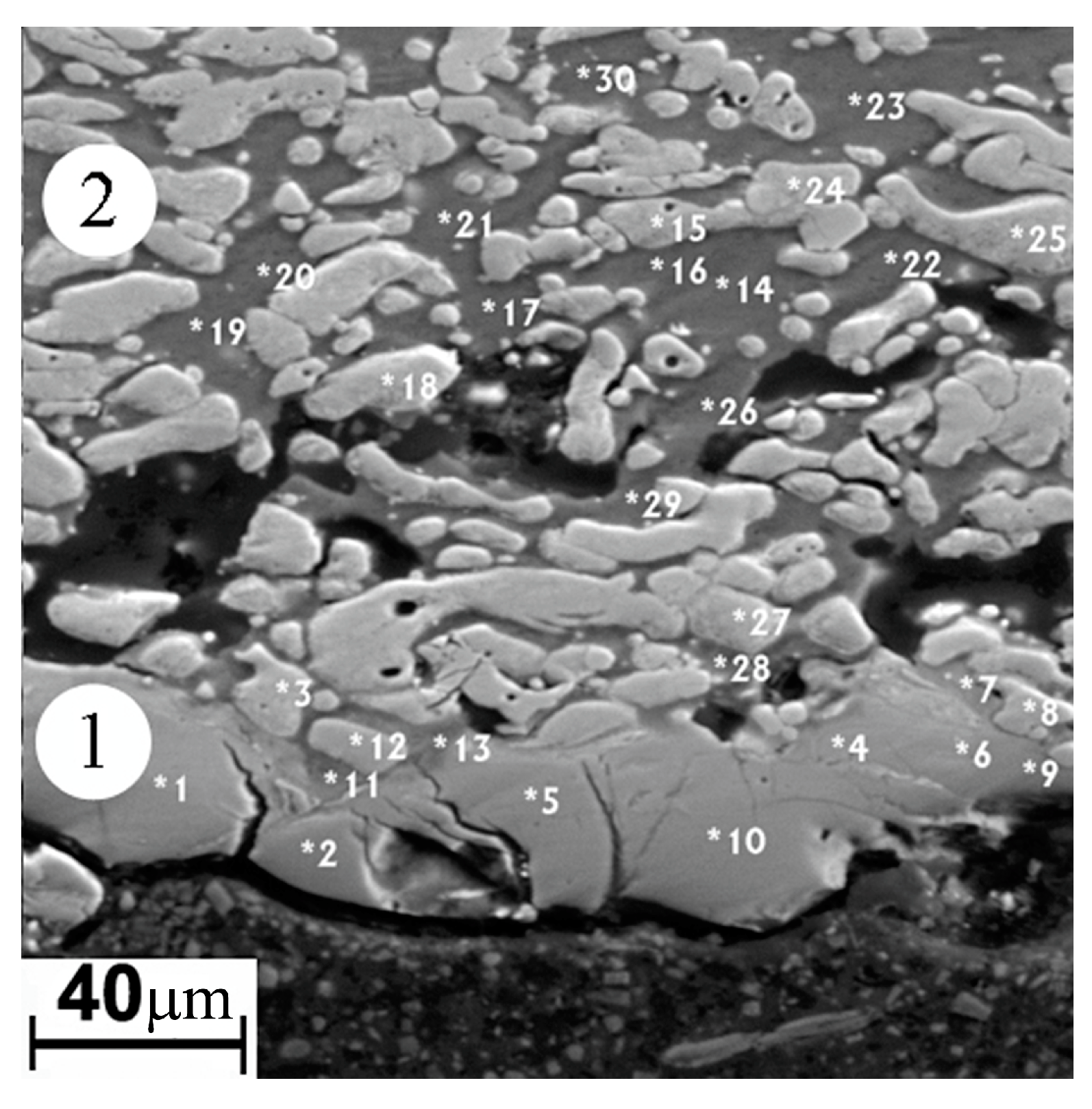
The thickness of the modified surface layer on the “Polema” cathode is 50–100 µm (zone 1 in Figure 6). Approximately half of the thickness is occupied by a layer adjacent to the arc-exposed surface layer with defects in the form of cracks and crumbled areas. The elemental composition of the continuous layer (Table 5) corresponds to the two-phase region Ti3Al + TiAl. This is consistent with the results of the X-ray phase analysis (Table 2). The origin of the layer is undoubtedly associated with the interaction of Ti and Al in the pressed powder mixture during arc heating. In some areas of this layer, there are small aluminum-enriched inclusions (points 7, 11, 13 in Figure 7). Between the continuous surface layer and the underlying starting material, there is a transition region with cavernous defects. The formation of the cavities in the transition region can be explained by the partial melting of low-melting aluminum and the migration of liquid Al between Ti particles under the action of a temperature gradient. It leads to a nonuniform distribution throughout the volume and the formation of voids during crystallization.

Figure 6.
Image of the modified layer “Polema” cathode in backscattered electrons. 1—arc exposed surface layer; 2—back surface layer. Spots of local elemental analysis are indicated with the numbers (Table 5).

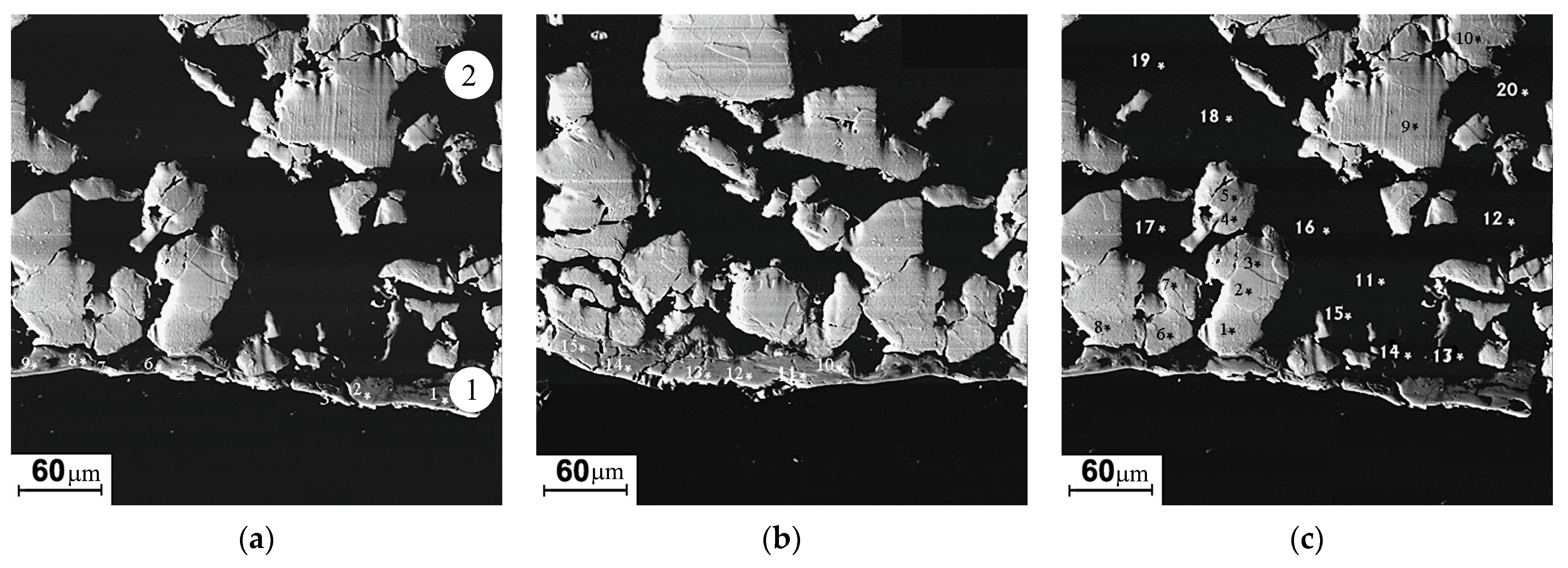
Figure 7.
Image of the modified layer “Umicore” cathode in backscattered electrons (a–c). 1—arc exposed surface layer; 2—back surface layer. Spots of local elemental analysis are indicated with the numbers (see Table 6).
3.2.4. Cathode No. 3, “Umicore”
The thickness of the modified layer on the “Umicore” cathode (zone 1) is significantly less than that on the “Polema” cathode and varies widely. The formation of the intermetallic compounds’ layer in the modified layer of the “Umicore” cathode originates from the same mechanism as for the “Polema” cathode. It is associated with the interaction of Ti and Al at the interphase boundaries of particles. However, due to the large size of Ti particles at the “Umicore” cathode and the small specific surface area of the Ti-Al interphase boundaries, the intermetallic layer has a small and irregular thickness, up to zero in some areas of the modified layer (Figure 7). According to the results of local elemental analysis, the visually unchanged structure of the cathode material adjacent to the surface intermetallic layer consists of large Ti particles in an aluminum matrix (Figure 7, Table 6, zone 2).
Table 6.
Results of elemental analysis of the modified surface layer of the “Umicore” cathode.
4. The Discussion of the Results
The thermodynamic driving force of structural transformations in the surface layer of cathodes is explained by the decrease in the free energy of the system during its transition from the initial non-equilibrium state to the equilibrium one. The greater the degree of non-equilibrium of the initial structural state, the greater the magnitude of the driving force. The “Polema” cathode compacted from the mechanical mixture of fine Ti and Al powders, has the most non-equilibrium structure of all the studied cathodes. The starting structure of the “Umicore” cathode is located nearer to the equilibrium than that of the “Polema” cathode since it is compacted from coarser powders and contains titanium aluminides. The non-equilibrium structure of the sintered cathode is determined by the presence of significant porosity and islands of the residual TiAl3 phase. The single-phase structure of the cast cathode with the minimum porosity is closest to equilibrium.
The transition rate of the starting structure to the equilibrium state also depends on the temperature. The temperature on the arc-treated surface of the cathode in a stationary mode of arc treating and the thickness of the modified surface layer depend on the rate of heat removal from the working surface of the cathode through its body towards the back water-cooled surface. The heat transfer rate is defined by the thermal conductivity of the cathode material, which, in turn, depends on its structure and phase composition.
The structural changes on the surface of the cast cathode consist of a slight surface melting and cracking of the surface layer under vacuum arc heating. The main reason for melting and cracking is probably the low thermal conductivity of titanium aluminides (26.4 W/(m∙K)) for TiAl, which differs little from the thermal conductivity of pure Ti (22 W/(m∙K)) [29]. The rate of heat removal from the working surface of the sintered cathode is significantly lower due to its increased porosity, which led to a thickness of the melted layer on the cathode surface of 400 μm. The presence of a relatively thick film of liquid metal on the cathode surface at high arc currents leads to the formation of drops and a deterioration in the quality of the deposited coating.
The thermal conductivity of the hot-pressed “Polema” and “Umicore” cathodes, which consist of a mechanical mixture of Ti and Al powders, is several times higher than the thermal conductivity of cast and sintered cathodes. The reason is that hot-pressed cathodes contain aluminum with a thermal conductivity of 237 W/(m∙K) [29], which is an order of magnitude higher than that of the titanium aluminides. Despite the high thermal conductivity of the hot-pressed cathodes, the temperature in the modified layer exceeds the Al melting point.
The higher surface temperature of the “Polema” cathode resulted in the thicker melted layer can be associated with additional heat influx from exothermic reaction in the dispersed mechanical mixture of Ti and Al particles with the formation of titanium aluminides. In the modified layer of the “Umicore” cathode, compacted from coarse powders, titanium aluminides are formed only in a thin surface layer of irregular thickness (Figure 4).
Let us compare the studied cathodes from the point of view of the best applicability in the coating technology. Sintered and cast cathodes appear to be unsuitable for the following reasons. The thick layer of the melt generated by the vacuum arc on the surface of the sintered cathode is the source of metal drops. The drops deposit on the coating surface resulting in bad roughness. Thermal cracks in the modified layer of the cast cathode can result in destruction and rapid erosion of the cathode. The most suitable for practical use seems to be cathode No. 2 (“Polema”) with a homogeneous structure, which consists of fine Ti grains in an Al matrix.
5. Conclusions
The structural transformations occur in the modified surface layer of Ti-Al cathodes when they are heated by a vacuum arc. The intensity and consequences of such structural transformations depend on the initial structure and phase composition of the cathode material. The most significant changes were revealed in the modified layer of the “Polema” cathode, in which a dispersed mechanical mixture of Ti and Al particles transforms into a continuous intermetallic layer up to 100 µm thick. The “Polema” cathode seems to be the most suitable for use in vacuum arc coating technology due to the homogeneous structure and moderate thickness of the modified surface layer.
Author Contributions
G.P.: conceptualization, methodology, supervision, experimental design, manuscript writing, project administration; I.F.: formal analysis, investigation, data handling, visualization, translation; V.K.: formal analysis, investigation, conducting XRD-analysis, data handling. All authors have read and agreed to the published version of the manuscript.
Funding
The work was performed according to the Government research assignment for ISPMS SB RAS, project FWRW-2021-0005.
Institutional Review Board Statement
Not applicable.
Informed Consent Statement
Not applicable.
Data Availability Statement
The data presented in this study are available on request from the corresponding author.
Conflicts of Interest
The authors declare no conflict of interest.
References
- Coll, B.F.; Sanders, D.M. Design of vacuum arc-based sources. Surf. Coat. Technol. 1996, 81, 42–51. [Google Scholar] [CrossRef]
- Sanchette, F.; Ducros, C.; Schmitt, T.; Steyer, P.; Billard, A. Nanostructured hard coatings deposited by cathodic arc deposition: From concepts to applications. Surf. Coat. Technol. 2011, 205, 5444–5453. [Google Scholar] [CrossRef]
- Veprek, S.; Veprek-Heijman, M.G.J.; Karvankova, P.; Prochazka, J. Different approaches to superhard coatings and nanocomposites. Thin Solid Films 2005, 476, 1–29. [Google Scholar] [CrossRef]
- Nurnberg, A.W.; Fang, D.Y.; Bauder, U.H. Temperature dependence of the erosion of Al and TiC by vacuum arcs in a magnetic field. J. Nucl. Mater. 1981, 103–104, 305–308. [Google Scholar] [CrossRef]
- Pribytkov, G.; Korzhova, V.; Korosteleva, E.; Krinitcyn, M. Effect of Silicon on the Surface Modification of Al-Cr Powder Cathodes Subjected to Vacuum Arc Treatment. Coatings 2022, 12, 958. [Google Scholar] [CrossRef]
- Rafaja, D.; Polzer, C.; Schreiber, G.; Polcic, P.; Kathrein, M. Surface modification of Ti-Al targets during cathodic arc evaporation. Surf. Coat. Technol. 2011, 205, 5116–5123. [Google Scholar] [CrossRef]
- Syed, B.; Zhu, J.; Polcik, P.; Kolozsvari, S.; Hakansson, G.; Johnson, L.; Ahlgren, M.; Joesaar, M.; Oden, M. Morphology and microstructure evolution of Ti-50 at.% Al cathodes during cathodic arc deposition of Ti-Al-N coatings. J. Appl. Phys. 2017, 121, 245309. [Google Scholar] [CrossRef]
- Zhu, J.Q.; Johansson-Jöesaar, M.P.; Polcik, P.; Jensen, J.; Greczynski, G.; Hultman, L.; Odén, M. Influence of Ti–Si cathode grain size on the cathodic arc process and resulting Ti–Si–N coatings. Surf. Coat. Technol. 2013, 235, 637–647. [Google Scholar] [CrossRef]
- Koller, C.M.; Hahn, R.; Ramm, J.; Kolozsvári, S.; Mayrhofer, P.H. Microstructural modifications in powder-metallurgically produced Al0.675Cr0.275Fe0.05 targets during cathodic arc evaporation. J. Vac. Sci. Technol. A 2016, 34, 021603. [Google Scholar] [CrossRef]
- Zöhrer, S.; Golizadeh, M.; Koutná, N.; Holec, D.; Anders, A.; Franz, R. Erosion and cathodic arc plasma of Nb-Al cathodes: Composite versus intermetallic. Plasma Sources Sci. Technol. 2020, 29, 025022. [Google Scholar] [CrossRef]
- Anders, A.; Yotsombat, B.; Binder, R. Correlation between cathode properties, burning voltage and plasma parameters of vacuum arcs. J. Appl. Phys. 2001, 89, 7764. [Google Scholar] [CrossRef]
- Eriksson, A.O.; Zhirkov, I.; Dahlqvist, M.; Jensen, J.; Hultman, L.; Rosen, J. Characterization of plasma chemistry and ion energy in cathodic arc plasma from Ti-Si cathodes of different compositions. J. Appl. Phys. 2013, 113, 163304. [Google Scholar] [CrossRef]
- Syed, B.; Joesaar, M.J.; Polcek, P.; Kolozsvari, S.; Hakansson, G.; Johnson, L.; Ahlgren, M.; Oden, M. Effect of work function and cohesive energy of the constituent phases of Ti-50 at.% Al cathode during arc deposition of Ti-Al-N coatings. Surf. Coat. Technol. 2019, 357, 393–401. [Google Scholar] [CrossRef]
- Rosen, J.; Anders, A.; Hultman, L.; Schneider, J.M. Temporal development of the composition of Zr and Cr cathodic arc plasma streams in a N2 environment. J. Appl. Phys. 2003, 94, 1414–1419. [Google Scholar] [CrossRef]
- Franz, R.; Polcik, P.; Anders, A. Element- and charge-state-resolved ion energies in the cathodic arc plasma from composite AlCr cathodes in argon, nitrogen and oxygen atmospheres. Surf. Coat. Technol. 2015, 272, 309–321. [Google Scholar] [CrossRef]
- Zhirkov, I.; Landalv, L.; Gothelid, E.; Ahlgren, M.; Eklund, P.; Rosen, J. Effect of Si on DC arc plasma generation from Al-Cr and Al-Cr-Si cathodes used in oxygen. J. Appl. Phys. 2017, 121, 083303. [Google Scholar] [CrossRef]
- Zhirkov, I.; Petruhins, A.; Polcik, P.; Kolozsvári, S.; Rosen, J. Effect of Ti-Al cathode grain size on plasma generation and thin film synthesis from a direct current vacuum arc plasma source. AIP Adv. 2019, 9, 045008. [Google Scholar] [CrossRef]
- Zhirkov, I.; Oks, E.; Rosen, J. Effect of N2 and Ar gas on DC arc plasma generation and film composition from Ti-Al compound cathodes. J. Appl. Phys. 2015, 117, 213301. [Google Scholar] [CrossRef]
- Zhirkov, I.; Eriksson, A.O.; Petruhins, A.; Dahlqvist, M.; Ingason, A.S.; Rosen, J. Effect of Ti-Al cathode composition on plasma generation and plasma transport in direct current vacuum arc. J. Appl. Phys. 2014, 115, 123301. [Google Scholar] [CrossRef]
- Zhu, J.; Eriksson, A.; Ghafoor, N.; Johansson, M.P.; Sjolen, J.; Hultman, L.; Rosén, J.; Odén, M. Characterization of worn Ti-Si cathodes used for reactive cathodic arc evaporation. J. Vac. Sci. Technol. A 2010, 28, 347–353. [Google Scholar] [CrossRef]
- Franz, R.; Mendez-Martin, F.; Hawranek, G.; Polcik, P. Erosion behavior of composite Al-Cr cathodes in cathodic arc plasmas in inert and reactive atmospheres. J. Vac. Sci. Technol. A 2016, 34, 021304. [Google Scholar] [CrossRef]
- Pohler, M.; Franz, R.; Ramm, J.; Polcik, P.; Mitterer, C. Cathodic arc deposition of (Al,Cr)2O3: Macroparticles and cathode surface modifications. Surf. Coat. Technol. 2011, 206, 1454–1460. [Google Scholar] [CrossRef]
- Kameneva, A.; Antonova, N.; Pesin, M.; Makarov, V.; Nikitin, S.; Bublik, N. Structural and phase transformations control in Ti and Al cathode materials, WC-Co substrate, and Ti1−xAlxN coating to improve their physico-mechanical and wear properties. Int. J. Refract. Met. Hard Mater. 2022, 102, 105726. [Google Scholar] [CrossRef]
- Holzapfel, D.M.; Music, D.; Hans, M.; Wolff-Goodrich, S.; Holec, D.; Bogdanovski, D.; Arndt, M.; Eriksson, A.O.; Yalamanchili, K.; Primetzhofer, D.; et al. Enhanced thermal stability of (Ti,Al)N coatings by oxygen incorporation. Acta Mater. 2021, 218, 117204. [Google Scholar] [CrossRef]
- Koller, C.M.; Glatz, S.A.; Kolozsvári, S.; Bolvardi, H.; Mayrhofer, P.H. Thermal stability and oxidation resistance of architecturally designed Ti–Al–N- and Ti–Al–Ta–N-based multilayers. Surf. Coat. Technol. 2020, 385, 125444. [Google Scholar] [CrossRef]
- Schalk, N.; Weirather, T.; Polzer, C.; Polcik, P.; Mitterer, C. A comparative study on Ti1−xAlxN coatings reactively sputtered from compound and from mosaic targets. Surf. Coat. Technol. 2011, 25, 4705–4710. [Google Scholar] [CrossRef]
- Pribytkov, G.A.; Andreeva, I.A.; Korjova, V.V. Bulk changes and structure formation in solid phase sintering of Ti–TiAl3 powder mixtures. Powder Metall. Met. Ceram. 2008, 47, 687–692. [Google Scholar] [CrossRef]
- Phase Equilibrium Diagrams, Datebase, Version 3.1; American Ceramic Society: Columbus, OH, USA, 2006.
- Binnewies, M.; Milke, E. Thermochemical Data of Elements and Compounds; Wiley-VCH Verlag GmbH: Weinheim, Germany, 2002; 919p. [Google Scholar]

Disclaimer/Publisher’s Note: The statements, opinions and data contained in all publications are solely those of the individual author(s) and contributor(s) and not of MDPI and/or the editor(s). MDPI and/or the editor(s) disclaim responsibility for any injury to people or property resulting from any ideas, methods, instructions or products referred to in the content. |
© 2023 by the authors. Licensee MDPI, Basel, Switzerland. This article is an open access article distributed under the terms and conditions of the Creative Commons Attribution (CC BY) license (https://creativecommons.org/licenses/by/4.0/).