Article

Effect of Bias Voltage on Structure, Mechanical Properties, and High-Temperature Water Vapor Corrosion of AlCrNbSiTi High Entropy Alloy Coatings

1
CNOOC Safety & Technology Service Co., Ltd., Tianjin 300450, China
2
School of Power & Mechanical Engineering, Wuhan University, Wuhan 430072, China
3
Shenyang Lebei Vacuum Technology Co., Ltd., Shenyang 110131, China
4
Shenzhen Research Institute, Wuhan University, Shenzhen 518057, China
*
Authors to whom correspondence should be addressed.
Coatings 2023, 13(11), 1948; https://doi.org/10.3390/coatings13111948
Submission received: 8 September 2023 / Revised: 19 October 2023 / Accepted: 2 November 2023 / Published: 15 November 2023

Abstract

:
Fuel cladding tubes are devices used in reactors to encapsulate fuel clots and transmit heat to coolants. However, zirconium alloy materials which are widely used in the fuel cladding pipe of pressurized water reactors have noticeable safety risks in resisting design basis accidents. Therefore, it is very important to improve the corrosion resistance of fuel envelope tubes to high-temperature water vapor oxidation. High-entropy alloys are considered to be a potential protective coating material for cladding tubes. In this study, AlCrNbSiTi high-entropy alloy (HEA) coatings were prepared by magnetron sputtering at different bias voltages. The effect of bias on coating morphologies, structure, mechanical properties, and resistance to high-temperature water vapor corrosion were studied. Experimental results showed that the bias significantly affects the coating surface roughness. In terms of mechanical properties, the sample at 50 V bias exhibited maximum hardness and elastic modulus of 18.2 GPa and 232.4 GPa, respectively. The highest adhesive force of the coating to the substrate of 36 N was obtained at 100 V bias. The optimum water vapor corrosion resistance of the AlCrNbSiTi HEA coating was achieved at 50 V bias, in which sample-point corrosion was the main corrosion failure mechanism.

1. Introduction

In underwater loss accidents (LOCA), the cladding material is prone to be oxidized rapidly, which will cause severe crack failure [1]. After the Fukushima nuclear accident, scientists have extensively studied accident fault-tolerant fuel (ATF) for use in pressurized water reactors [2]. The ATF coating can delay the time of fuel rod expansion and explosion, reduce the heating rate of the envelope, and subsequently delay the progress of serious accidents [3]. For ATF coating, the most critical requirement is to reduce the high-temperature water vapor oxidation rate during the accident time [4]. Research of ATF cladding materials is focused on two categories, the first of which is to develop new antioxidant cladding materials such as iron-based alloys, SiC ceramics, and tristructural isotropic (TRISO) fuel particles. However, the cladding materials studied have obvious disadvantages, such as the poor high temperature mechanical properties of iron-based alloys, the high thermal neutron capture section coefficient of FeCrAl alloys, and the high production cost of SiC ceramic tubes. The second approach is to prepare various special protective coatings on the surface of the material to improve its high-temperature water vapor oxidation performance. Since the protective coatings have no negative effects on the comprehensive performance of the substrate, the composition of the coating materials plated on the surfaces is easy to design, which can maximize its resistance to water vapor oxidation and greatly improve the service performance of the reactor components.
At present, the research on surface protective coatings of cladding materials mainly focuses on metal and ceramic coatings. Cr coating is the most commercial application of zirconium alloy surface accident-resistant coating [5,6,7]. Cr-coated zirconium alloy has excellent corrosion resistance under normal service conditions, but the thermal neutron capture cross-section coefficient of the pure Cr layer is relatively high, which affects the economic benefit of nuclear fuel. Metal coatings such as FeCrAl are not susceptible to massive oxidation or corrosion at high temperature because of the formation of protective alumina oxide layers [8]. However, the thickness of the FeCrAl coating must be tens of microns to effectively enhance the antioxidant capability of the zirconium alloy cladding. Moreover, Zr alloy and FeCrAl tend to interdiffuse at high temperature, which will reduce the mechanical properties of the shell. Therefore, although metal coatings have excellent toughness and adhesion with metal substrate, as well as desirable resistance to water vapor oxidation, a certain thickness is usually necessitated, while a high thickness is always accompanied by high neutron absorption rate and interdiffusion between coatings and substrates.
Ceramic coatings have excellent oxidation resistance in water vapor because of their good thermal stability and chemical stability. Currently research is mainly focused on MAX phase coatings, such as nitride coatings and carbide coatings. As compared with other ceramic materials, MAX phase coatings have relatively better toughness and larger ductility in low-speed creep. However, the interdiffusion with Zr substrate is more significant at high temperatures, and the ceramic layer and the interdiffusion area are both fairly brittle, which will result in cracks after heat treatments. The rate of oxidation of TiAlN coatings was reduced by more than one order of magnitude as compared with uncoated pure Zr alloys [9]. CrN-based nitride coatings are also reported as alternative materials for accident-resistant coatings on zirconium alloy surfaces [10]. Results showed that the CrN coatings did not show any traces of cracking and shedding even at 1160 °C. The comparative study of CrN, TiAlN, and AlCrN showed that the CrN coating sample had the best corrosion resistance in a pressurized Canadian heavy-water uranium reactor (CANDU) at, 300 °C, pH = 10.5, 30 d, and overheated water vapor (1100 °C, atmospheric pressure) environments. Oxidation tests showed that the weight gain of SiC-coated samples was about one-fifth less than zirconium alloy samples. However, because of the noticeable difference between the thermal expansion coefficient of SiC and zirconium alloy substrate, as well as the relatively poor binding strength between SiC coating and zirconium alloy substrate, the SiC coating is susceptible to fall off at high temperatures [11]. From the perspective of high-temperature water vapor oxidation resistance, ceramic coatings have excellent thermal stability and chemical stability, which are beneficial to stabilize the coatings in high-temperature water vapor and avoid the dissolution or rapid oxidation of the coatings. However, coating cracking is a typical drawback when the coatings were subjected to instant impact or complex stresses such as stretching and creep.
At present, there are some defects in the protective coating technology of cladding material, which limits its large-scale use. In order to meet the requirements of accident-resistant cladding materials, a high-entropy alloy coating is a feasible choice. High-entropy alloys have four major effects different from traditional alloys, namely, high-entropy effect in thermodynamics, lattice distortion effect in crystallography, hysteresis diffusion effect in dynamics, and cocktail effect in performance, which makes them have good mechanical properties and corrosion resistance [12,13], as well as great application potential in cladding tube protection [14]. In this research, the AlCrNbSiTi alloy system is used as the research object for the application of fuel cladding tube coating materials. The presence of Al and Si is conducive to improving the corrosion resistance of the coating. AlCrNbSiTi high-entropy alloy coatings were prepared by magnetron sputtering under different levels of bias. The effects of bias on the morphology, structure, and properties of the coatings were systematically studied, in order to provide reference for the application of high-entropy alloy coatings in water vapor corrosion protection.

2. Experiments Details

2.1. Coating Preparation

The instrument used in the preparation of the sample coating is the Nano-100 PVD deposition system. The coatings were deposited on single crystal Si (100) wafers, WC-6%Co cemented carbide substrates, and 304 stainless steel plates. The surface of the substrates was polished by a manufacturer and was not additionally mechanically treated. The coatings deposited on Si substrates were used to study the surface and cross section morphology of the coatings. Samples on 304 stainless steel substrates were used for XRD, mechanical properties, residual stress, and water vapor corrosion testing. The coatings deposited on cemented carbide substrates were used for the scratch test. Prior to coating deposition, the substrates were ultrasonically cleaned in acetone for 15 min. The cleaned samples were dried and placed on the sample holder in the vacuum chamber. When the vacuum chamber pressure reached 4 × 10⁻³ Pa and the heating temperature was 200 °C, ion etching was applied with a target current set to 100 A at 0.5 Pa. The etching time was 30 min and the bias was 150 V with a 50% duty ratio. After etching, the coating was deposited. The Al34Cr22Nb11Si11Ti22 target (Sibote, 99.95% purity) was used for magnetron sputtering at the RF power of 700 W. The Ar pressure was fixed at 0.5 Pa and the sample negative bias voltage was set to 0 V, 50 V, 100 V, 150 V, and 200 V with a duty cycle of 50%. The deposition time was 1 h.

2.2. Coating Characterization

2.2.1. Morphology and Structure

The samples surface and cross section were studied by Scanning Electron Microscope (SEM) MIRA 3 and Atomic Force Microscope (AFM) Shimadzu SPM-9500 J3. The thickness and roughness of the coating was measured at three–four points and the average values were taken. The composition of the coatings was analyzed using an Energy Dispersive Spectrometer (EDS) Aztec Energy X-Max 20. The phase composition of the coatings was characterized by X-ray diffractometer (XRD) Tongda TDM-10.

2.2.2. Residual Stress Test

The residual stress is tested by the curvature method, using the stress tester Supu FST2000 to obtain the curvature change of the specimen before and after the coating deposition. Each sample was measured 3 times and the average value was taken. The residual stress of the coating is calculated according to the Stoney equation:
σ film = E s h s 2 6 ( 1 ν s ) h f ( 1 R f 1 R s )
where, E S , h S , and V S are the elastic modulus, thickness, and Poisson ratio of the substrate, respectively, h f is the thickness of the coating, R f and R S are the curvature of the coating and substrate, respectively.

2.2.3. Mechanical Properties

Hardness and elastic modulus were measured using a nanoindentation instrument NANO G200. The test uses the continuous stiffness method, and the penetration depth does not exceed 10% of the coating thickness, in order to reduce the influence of substrate effects. Each sample was measured at 6 points and averaged. The multifunctional material surface performance test instrument Huahui MFT-4000 was used for scratch testing to study adhesion force of the coating. During the scratch test, the indenter scratches the coating at a constant speed, and the load increases uniformly from 0 N to the 150 N. The loading speed is 100 N/min, and the scratch distance is 5 mm. Each sample was tested three times and averaged.

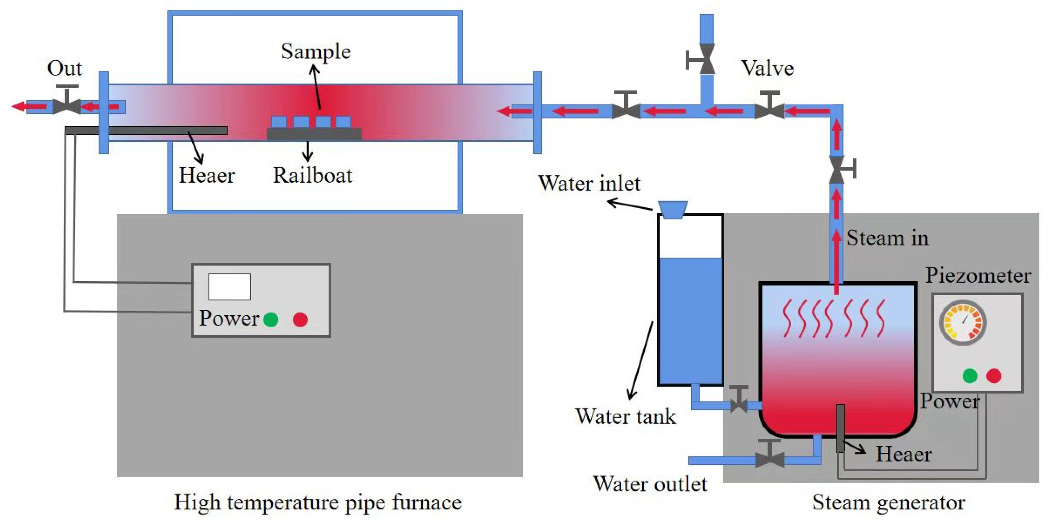
2.2.4. Water Vapor Corrosion Test

The water vapor corrosion experiment can simulate the accident fault tolerance test of the coating in high-temperature water vapor environments. The experiment was conducted on a custom-built laboratory platform, shown in Figure 1. In Figure 1, the right-side device is the water vapor generator. The left device is a high-temperature tube furnace with a set temperature of 700 °C. After the temperature reached the set temperature, the water vapor generator was applied with an outlet pressure of 0.3 MPa. The samples were placed into it for 10, 50, 140, 200 h. Deionized water was added into the tank every 10 h to maintain the outlet pressure of the steam generator.

3. Results and Discussion

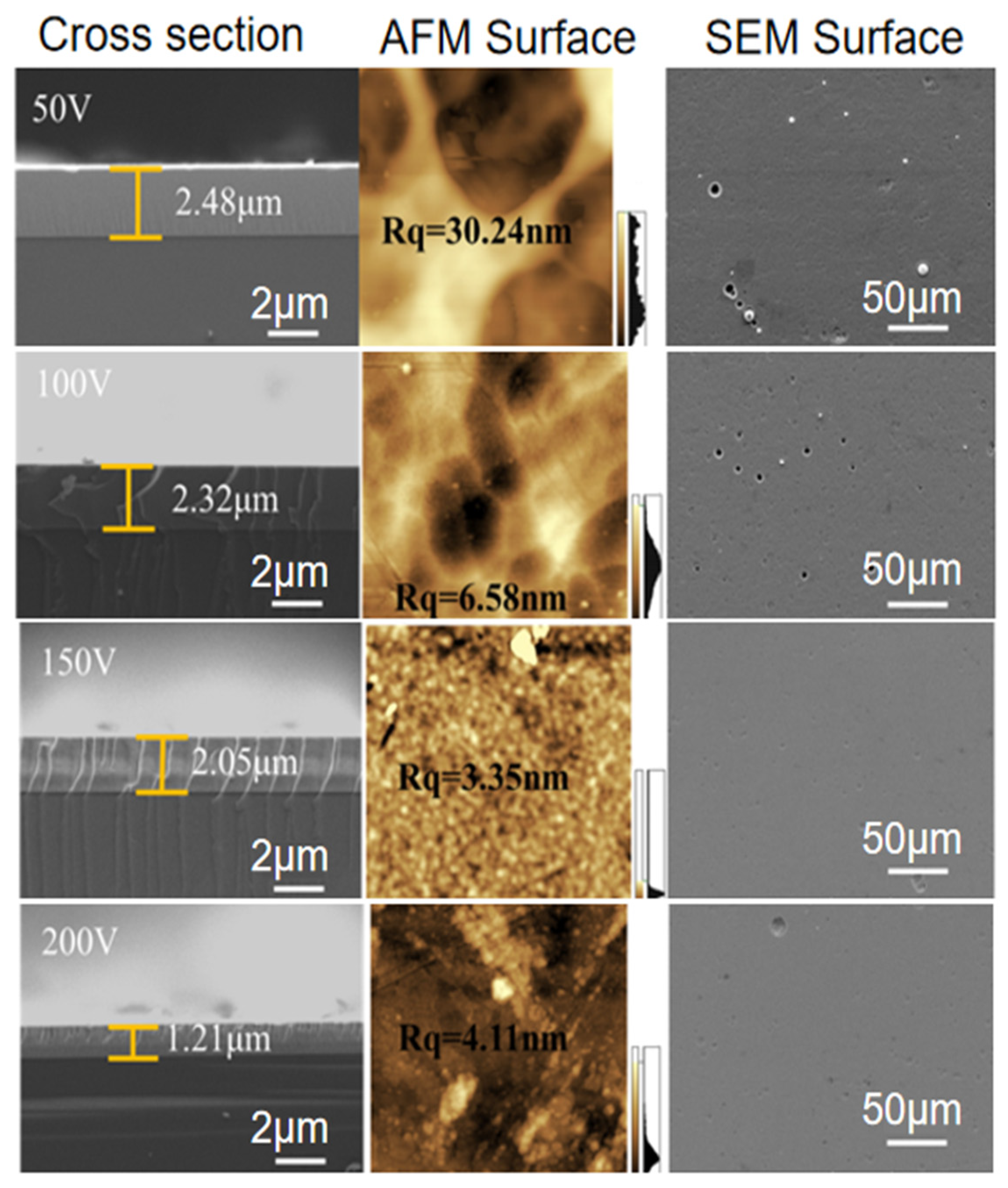
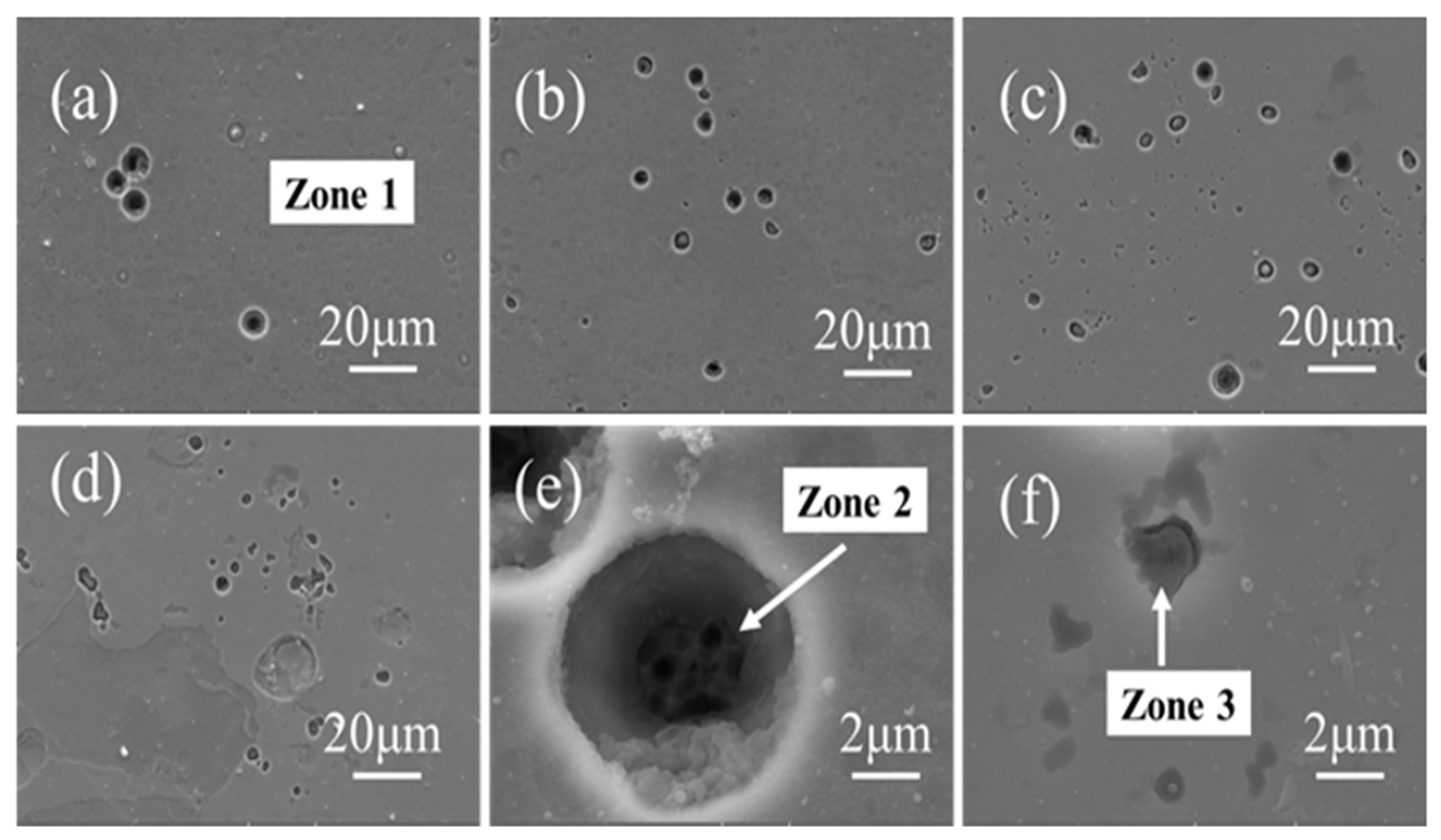
3.1. Coating Morphology

Cross-section morphology and surface roughness of the samples deposited under different bias voltage are shown in Figure 2. Surfaces of the samples prepared at different bias are smooth, and the number of surface particles decreases with increasing bias, while granular defects on the surface which are caused by contaminants in the substrate, the vacuum chamber, and the target are unavoidable defects in PVD coatings. In terms of defects from the substrate, particle defects may be also introduced during the residual polishing, cleaning, and drying prior to deposition, as well as residual dust, debris, and other impurities [15]. Granular defects produced in the vacuum chamber mainly come from the process of vacuum, heating, bombardment, or deposition, from the dust particles on the internal components of the vacuum system [16]. Granular defects caused by the target material are mainly due to the particle eruption introduced during the magnetron sputtering process [11]. The particles are incorporated into the coating, and the structure around the particle defects are loosened due to the masking effect and the low thermal mobility of the atoms, which will result in low ion collision energy. Under the action of external force, the particles are prone to fall off and thus form holes. As shown in Figure 2, the pits on the surface of the coating are caused by the loss of large particles under the bombardment by high-energy ions of the biased sample.
It can be seen from the cross-sectional images of the coatings that all coatings are smooth and dense, without obvious hole defects. The coating thickness is gradually reduced from 2.5 ± 0.2 μm to 1.2 ± 0.2 μm with the increasing bias from 50 V to 200 V. As the bias increases, the coating thickness decreases for two main reasons. First, the bombardment energy is enhanced due to high bias, and the intervoid of the coating grains is filled during deposition, which promotes the densification of the coating surface, reduces the deposition rate, and decreases the coating thickness [17]. On the other hand, under the condition of high bias, the resputtering effect is enhanced, which also leads to the decrease in deposition rate and the decrease in coating thickness.
According to the AFM results, as shown in Figure 2, root-mean-square roughness Rq gradually decreases from 31 ± 5 nm to 6 ± 1 nm while the bias increases from 50 V to 100 V. The reason why the surface roughness of the coating is greatly affected is that in the initial stage of coating deposition, the coating will reproduce the uneven surface morphology of the substrate after ion etching. At low bias, it is more difficult to obtain atomic supplement in the depressed area than in the prominent area due to the geometric shielding effect, so the difference between the two parts gradually increases with the deposition process. The surface roughness of the coating is greater. Correspondingly, under high bias, the bombardment of high-energy particles will erode the protruding parts of the coating surface and weaken the geometric shielding effect. In addition, the increase in bias also leads to the enhancement of the resputtering effect, and the atomic supplement rate of the depressed part and the protruding part becomes close, so the coating shows a lower surface roughness. When the bias is higher than 150 V, the bias exhibits slight influence on the surface roughness. As shown in the surface SEM images of the coatings, fewer holes and particles can be observed at higher bias.
EDS mapping of the coating surfaces and cross sections are shown in Figure 3 and Figure 4, respectively. The coating was deposited at bias voltage of 100 V. The five elements of the coatings are evenly distributed without obvious segregation. In the EDS images of the cross section, Si is both the substrate and coating element.
The element content change of the coating measured using EDS is shown in Figure 5. With a bias of 50 V, the Al content is the highest of about 26 at.%. The amount of Al decreases significantly as the bias increases. Due to its light mass, the Al is susceptible to a back-sputtering phenomenon, resulting in less Al ions reaching the substrate or Al ions being bombarded out from the deposited coatings [18]. When the bias increases from 50 V to 100 V, the content of Al decreases from about 26 at.% to about 14 at.%. Samples with a bias of 100 V, 150 V, and 200 V have the highest content of Cr of about 28 at.%, 30 at.%, and 31 at.%, respectively.

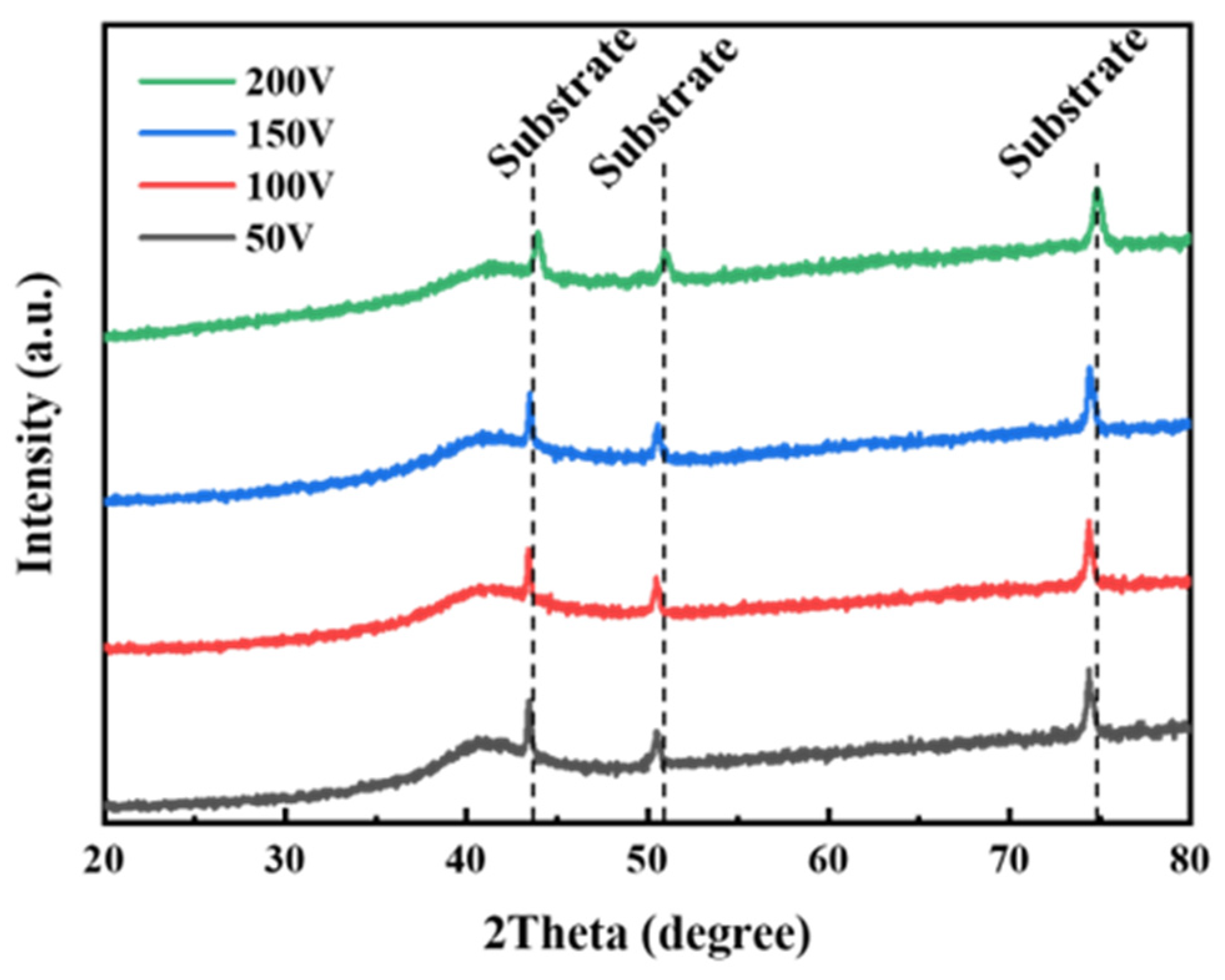
3.2. Crystal Structure of the Coating

XRD patterns of the coatings deposited at different levels of bias are shown in Figure 6. The three peaks annotated in the figure are the diffraction peaks of the 304 stainless steel substrate. The diffraction peak of the coating is a single broadened diffraction peak, which indicates that the coatings are amorphous or composed of small nano crystallites. The observed broad XRD peak probably belongs to FCC crystal lattice (200) reflection. The high mixing entropy, atomic size mismatch of high-entropy alloy elements, and the fast cooling rate of coatings during the deposition process benefit the development of amorphous samples [19]. Similar results of amorphous states are observed in the AlCrMoSiTi alloy [20].

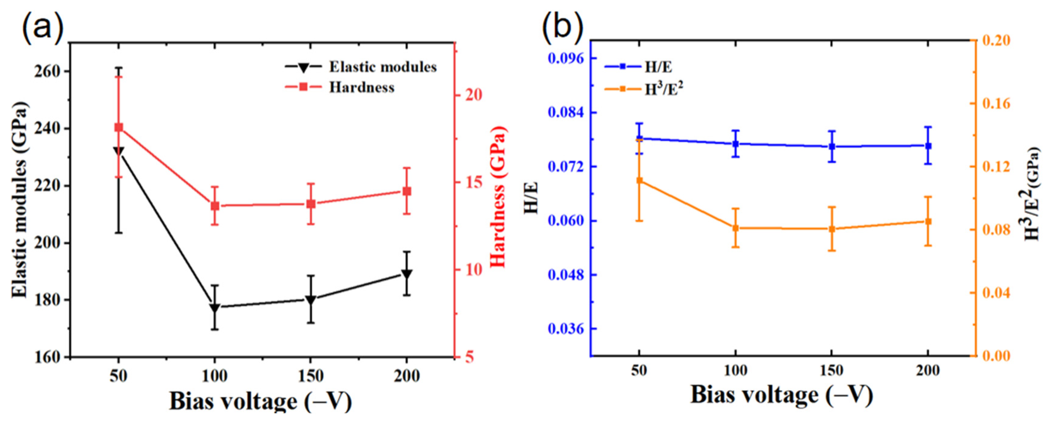
3.3. Mechanical Properties of the Coating

The hardness and elastic modulus of the coatings are shown in Figure 7a. The hardness and elastic modulus have the same change trend that they gradually decrease as the bias increases. At 50 V, highest hardness and elastic modulus are achieved at 18 ± 3 GPa and 240 ± 15 GPa, respectively. In Figure 7b, H/E and H3/E2 are shown, which are generally used to evaluate the fracture toughness of hard coatings, especially in ceramic materials [21]. H/E and H3/E2 of the coatings have similar variation trends with hardness and elastic modulus. When the bias is 50 V, the coating has the highest H/E and H3/E2, which are 0.08 and 0.11 GPa, respectively. When the bias is 200 V, H/E and H3/E2 drop to 0.075 and 0.085 GPa, respectively.
The residual stress of the coatings is shown in Figure 8. All the coatings showed residual compressive stress. At 150 V, the highest residual compressive stress is 3.5 GPa, while the lowest residual stress is 1.4 GPa at 200 V. The residual stress of the coatings results from the bombardment effect of high-energy ions. Under negative bias, the ions sputtered by the target material and the working gas ions close to the target material have an energy between 10 eV and 100 eV when moving to the substrate. The high-energy ions produce an ion peening effect on the substrate, producing defects and also causing the increase in residual pressure stress. However, at the same time, the mobility of the surface-adsorbed atoms rises due to the collision of high-energy ions to the surface of the substrate, which also promotes the fusion of defects and reduces the residual stress [22]. The final residual stress is determined by the competition of these two above factors.

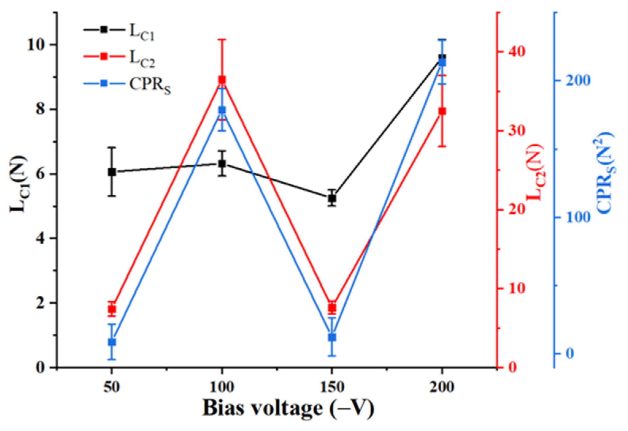
3.4. Coating Scratch Toughness

Scratch toughness results of the coatings are shown in Figure 9. In the scratch experiment, scratches are generally divided into three stages. The first stage is the initial cracking stage, the second stage is the initial peeling stage, and the third stage is the complete peeling stage. These three phases correspond to the three critical loads, Lc1, Lc2, and Lc3. However, if the coating binding force to the substrate is strong, the third stage may not occur. The scratch toughness of the coating is generally characterized by the crack extension resistance value (CPRs), which reflects the binding force between the coating and the substrate, as well as the toughness of the coating [23].
C P R s = L c 1 ( L c 2 L c 1 )
The values of Lc1, Lc2, and CPRS show the same variation trend. The 200 V bias coating has the strongest resistance to cracking, with an Lc1 value of 9 N. The samples coated with a bias of 100 V and 200 V were strongly bonded with Lc2 values of 36 N and 31 N, respectively. The 50 V bias coating has an Lc2 value of only 8 N. The scratch morphology of the AlCrNbSiTi high-entropy alloy coatings at different bias is shown in Figure 10. According to the CPRS value of the coatings with different levels of bias and the scratch images, scratch cracking occurred earlier for the sample with a bias of 50 V, and the coating peeled off at the beginning stage with CPRS of 10 ± 4 N2. At 100 V, the CPRS rises sharply to 190 ± 20 N2, and no third stage occurs. At 150 V, the coating cracks and flakes at the beginning of the experiment, indicating fairly poor binding force. The coating with 200 V bias has desirable scratch toughness and ability to resist cracking with outstanding binding force in all four samples, which can be attributed to the compaction of the coating at high bias. Some coating grinding chips are distributed at the peeling area of the scratch coatings with a bias voltage of 100 V and 200 V. Table 1 shows the composition of three different areas after the coating scratch test. The grinding chips element of the coating of 100 V bias has only 0.64 at.% W, while the other elements are all elemental components of the coating. Therefore, the grinding chips are formed by the breaking and peeling of the coating during the scratch experiment. Region B contains the W element of about 24 at.% and the Co element of 11 at.%, indicating that the coating here has been peeled off and exposed to the substrate. EDS results of region C show presence of Ti of 1.6 at.% and Cr of 1.5 at.%, showing that the coating has been completely peeled off.

3.5. Corrosion Resistance against Water Vapor

In the water vapor corrosion test, the temperature was set to 700 °C. Changes in the samples were monitored at different time periods of 10, 50, 100, 140, and 200 h. The surface morphology images of the corroded coatings are shown in Figure 11. The sample with a bias voltage of 50 V has corrosion pits after 140 h and 200 h, while samples of other bias voltages have corrosion pits after 50 h and 140 h. Two types of corrosion pits can be observed in the morphology images, as shown in Figure 12. One is the regular round corrosion pit, which mainly develops from the particle defects in the process of coating preparation. The other is the shallow corrosion pit with irregular depth, mainly because of the uneven corrosion in the corrosion process. Elemental analysis is performed for different corrosion regions as well as areas without defects, as shown in Table 2. The content of O in the defect-free area (Zone 1) and the irregular shallow pit area (Zone 3) is basically consistent. An Fe element of 65.0 at.% and Mn element of 11.0 at.% can be detected in the regular circular pit area (Zone 2). In addition, traces of elements of the substrate have been found in this region, indicating corrosion to the substrate.
The cross sections of the coatings corroded for 200 h were studied, there were no penetrating holes in the cross sections, and the coating was combined well with the substrate. The EDS results of the sample with a bias of 200 V are shown in Figure 13. All elements except Al are still evenly distributed in the coating. The distribution of Al element in the cross-section shows that the content of Al element near the surface of the coating is high, which is caused by the gradual diffusion of Al element to the surface during the experiment. This phenomenon can be observed in the coating at various levels of bias.
In discussed above, the influence of bias on water vapor corrosion resistance of the coatings is mainly based on three mechanisms. First, different levels of bias have substantial effects on the coating thickness, while a larger thickness can compensate for the particle defects on the surface and improve the corrosion resistance. For example, the thickness difference between 50 V and 200 V coating samples reaches 1.3 μm. Then, the element composition of the coatings differs noticeably under different levels of bias, in which Al, Cr, and Nb have great influences on the corrosion resistance of the coating. For example, the Al content difference between coating deposited at 50 V and 200 V bias reaches about 17 at.%, while 6.8 at.% of Cr and 5.8 at.% of Nb elements. Finally, bias affects the surface roughness of the coatings, when the particle defects on the coating surface are prone to point corrosion. Because of the large pores at the defect, the transmission channel of the corrosion medium is provided, leading to the aggravation of the corrosion phenomenon. With the increase in bias, the coating surface is more compact, alleviating the corrosion speed. Therefore, the synergistic action of many factors affects the water vapor corrosion resistance of the coating.

4. Conclusions

The AlCrNbSiTi high-entropy alloy coating was prepared by magnetron sputtering technique. Effects of bias voltage on coating morphology, mechanical, and corrosion properties were studied. With the increase in bias voltage, the resputtering effect during deposition and the increase in the density of the coating results in the decrease in the coating thickness from 2.5 ± 0.2 μm to 1.2 ± 0.2 μm. At the same time, the resputtering effect results in a decrease in the surface roughness of the coating from 31 ± 5 nm to 6 ± 1 nm. The increase in bias voltage changes the composition of the coating. Due to the light weight of Al atoms, the resputtering effect is strong during deposition; therefore, with the increase in bias voltage, the content of Al gradually decreases. The content of Ti is little affected by the bias and does not change significantly with the bias, while the content of Cr, Nb, and Si increases gradually with the increase in bias. The water vapor corrosion resistance of the coating changes significantly with the bias voltage. The sample with a bias voltage of 50 V has a corrosion pit between 140 h and 200 h of corrosion. The surface of other coatings has a corrosion pit between 50 h and 140 h of corrosion, and the phenomenon of Al element diffusion and enrichment to the surface has been observed in all the coatings.
In addition, the bias voltage also has obvious influence on the mechanical properties of the coating. With the increase in bias voltage, the hardness, elastic modulus, H/E, and H3/E2 of the coating decreased gradually. The bias increased from 50 V to 200 V, and decreased from 18.2 GPa, 232.4 GPa, 0.08 GPa, and 0.11 GPa to 14.5 GPa, 189.4 GPa, 0.075 GPa, and 0.085 GPa, respectively. The deposited coatings all show residual compressive stress, and the minimum residual compressive stress is 1.4 GPa in samples deposited at a bias of 200 V. The binding strength of the coating does not change significantly with the increase in bias voltage, and the binding strength of the coating and the substrate is the best when the bias voltage is 100 V with LC2 value of 36 N.
In summary, application of bias voltage can control water vapor corrosion resistance and other properties of AlCrNbSiTi HEA coatings. By selecting an appropriate bias, an AlCrNbSiTi high-entropy alloy coating with excellent water vapor corrosion resistance and mechanical properties can be obtained. It is of reference value for the application of AlCrNbSiTi high-entropy alloy coatings in the protection of fuel cladding tubes.

Author Contributions

Conceptualization, Y.C.; Methodology, H.W. and Y.C.; Software, H.B., Y.L., Z.W. and B.Y.; Validation, H.W. and W.L.; Formal analysis, Y.L.; Investigation, Z.Z.; Resources, H.B. and Z.W.; Data curation, X.W.; Writing—original draft, X.W.; Writing—review & editing, Z.Z. and Y.C.; Visualization, Z.W.; Supervision, Y.L. and B.Y.; Project administration, W.L. and B.Y.; Funding acquisition, W.L. and B.Y. All authors have read and agreed to the published version of the manuscript.

Funding

This work was supported by the Shenzhen Science and Technology Program (JCYJ20220530140601002), the National Natural Science Foundation of China (52371073) and the Sino-foreign Joint Research Platform Seed Foundation of Wuhan University (WHUZZJJ202223).

Institutional Review Board Statement

Not applicable.

Informed Consent Statement

Not applicable.

Data Availability Statement

Data are contained within the article.

Conflicts of Interest

The authors declare no conflict of interest.

References

  1. Hirano, M.; Yonomoto, T.; Ishigaki, M.; Watanabe, N.; Maruyama, Y.; Sibamoto, Y.; Watanabe, T.; Moriyama, K. Insights from review and analysis of the Fukushima Dai-ichi accident. J. Nucl. Sci. Technol. 2012, 49, 1–17. [Google Scholar] [CrossRef]
  2. Duan, Z.; Yang, H.; Satoh, Y.; Murakami, K.; Kano, S.; Zhao, Z.; Shen, J.; Abe, H. Current status of materials development of nuclear fuel cladding tubes for light water reactors. Nucl. Eng. Des. 2017, 316, 131–150. [Google Scholar] [CrossRef]
  3. Zinkle, S.; Terrani, K.; Gehin, J.; Ott, L.; Snead, L. Accident tolerant fuels for LWRs: A perspective. J. Nucl. Mater. 2014, 448, 374–379. [Google Scholar] [CrossRef]
  4. Zinkle, S.J.; Was, G.S. Materials challenges in nuclear energy. Acta Mater. 2013, 61, 735–758. [Google Scholar] [CrossRef]
  5. Bischoff, J.; Vauglin, C.; Delafoy, C.; Barberis, P.; Vassault, J.P.; Perche, D.; Guerin, B.; Brachet, J.C. Development of Cr-coated zirconium alloy cladding for enhanced accident tolerance. In Proceedings of the TOP FUEL 2016, Boise, ID, USA, 11–15 September 2016. [Google Scholar]
  6. Schuster, F.; Lomello, F.; Billard, A.; Velisa, G.; Monsifrot, E.; Bischoff, J.; Ambard, A.; Brachet, J.-C.; Lesaux, M.; Leflem, M.; et al. On-going studies at CEA on chromium coated zirconium based nuclear fuel claddings for enhanced accident tolerant LWRS fuel. In Proceedings of the Top FUEL 2015, Zurich, Switzerland, 13–19 September 2015. [Google Scholar]
  7. Park, J.-H.; Kim, H.-G.; Park, J.-Y.; Jung, Y.-I.; Park, D.-J.; Koo, Y.-H. High temperature steam-oxidation behavior of arc ion plated Cr coatings for accident tolerant fuel claddings. Surf. Coat. Technol. 2015, 280, 256–259. [Google Scholar] [CrossRef]
  8. Zhong, W.; Mouche, P.A.; Han, X.; Heuser, B.J.; Mandapaka, K.K.; Was, G.S. Performance of iron–chromium–aluminum alloy surface coatings on Zircaloy 2 under high-temperature steam and normal BWR operating conditions. J. Nucl. Mater. 2016, 470, 327–338. [Google Scholar] [CrossRef]
  9. Brova, M.J.; Alat, E.; Pauley, M.A.; Sherbondy, R.; Motta, A.T.; Wolfe, D.E. Undoped and ytterbium-doped titanium aluminum nitride coatings for improved oxidation behavior of nuclear fuel cladding. Surf. Coat. Technol. 2017, 331, 163–171. [Google Scholar] [CrossRef]
  10. Meng, C.; Yang, L.; Wu, Y.; Tan, J.; Dang, W.; He, X.; Ma, X. Study of the oxidation behavior of CrN coating on Zr alloy in air. J. Nucl. Mater. 2019, 515, 354–369. [Google Scholar] [CrossRef]
  11. Koski, K.; Hölsä, J.; Juliet, P. Surface defects and arc generation in reactive magnetron sputtering of aluminium oxide thin films. Surf. Coat. Technol. 1999, 115, 163–171. [Google Scholar] [CrossRef]
  12. Zhao, P.; Zhu, J.; Yang, K.; Li, M.; Shao, G.; Lu, H.; Ma, Z.; Wang, H.; He, J. Outstanding wear resistance of plasma sprayed high-entropy monoboride composite coating by inducing phase structural cooperative mechanism. Appl. Surf. Sci. 2023, 616, 156516. [Google Scholar] [CrossRef]
  13. Guo, Q.; Hou, H.; Pan, Y.; Pei, X.; Song, Z.; Liaw, P.K.; Zhao, Y. Hardening-softening of Al0.3CoCrFeNi high-entropy alloy under nanoindentation. Mater. Des. 2023, 231, 112050. [Google Scholar] [CrossRef]
  14. Wang, K.; Zhu, J.; Wang, H.; Yang, K.; Zhu, Y.; Qing, Y.; Ma, Z.; Gao, L.; Liu, Y.; Wei, S.; et al. Air plasma-sprayed high-entropy (Y0.2Yb0.2Lu0.2Eu0.2Er0.2)3Al5O12 coating with high thermal protection performance. J. Adv. Ceram. 2022, 11, 1571–1582. [Google Scholar] [CrossRef]
  15. Čekada, M.; Panjan, P.; Kek-Merl, D.; Panjan, M.; Kapun, G. SEM study of defects in PVD hard coatings. Vacuum 2007, 82, 252–256. [Google Scholar] [CrossRef]
  16. Mitterer, C.; Heuzè, O.; Derflinger, V.H. Substrate and coating damage by arcing during sputtering. Surf. Coat. Technol. 1997, 89, 233–238. [Google Scholar] [CrossRef]
  17. Zhang, S.; Sun, D.; Fu, Y.; Du, H.; Zhang, Q. Effect of sputtering target power density on topography and residual stress during growth of nanocomposite nc-TiN/a-SiNx thin films. Diam. Relat. Mater. 2004, 13, 1777–1784. [Google Scholar] [CrossRef]
  18. Lai, C.-H.; Lin, S.-J.; Yeh, J.-W.; Davison, A. Effect of substrate bias on the structure and properties of multi-element (AlCrTaTiZr)N coatings. J. Phys. D Appl. Phys. 2006, 39, 4628. [Google Scholar] [CrossRef]
  19. Ren, B.; Liu, Z.; Shi, L.; Cai, B.; Wang, M. Structure and properties of (AlCrMnMoNiZrB0.1)Nx coatings prepared by reactive DC sputtering. Appl. Surf. Sci. 2011, 257, 7172–7178. [Google Scholar] [CrossRef]
  20. Zhao, Y.; Chen, S.; Chen, Y.; Wu, S.; Xie, W.; Yan, W.; Wang, S.; Liao, B.; Zhang, S. Super-hard and anti-corrosion (AlCrMoSiTi)Nx high entropy nitride coatings by multi-arc cathodic vacuum magnetic filtration deposition. Vacuum 2022, 195, 110685. [Google Scholar] [CrossRef]
  21. Lackner, J.M.; Major, L.; Kot, M. Microscale interpretation of tribological phenomena in Ti/TiN soft-hard multilayer coatings on soft austenite steel substrates. Bull. Pol. Acad. Sci. Tech. Sci. 2011, 59, 343–355. [Google Scholar] [CrossRef]
  22. Sharifahmadian, O.; Mahboubi, F. A comparative study of microstructural and tribological properties of N-DLC/DLC double layer and single layer coatings deposited by DC-pulsed PACVD process. Ceram. Int. 2019, 45, 7736–7742. [Google Scholar] [CrossRef]
  23. Baer, D.R.; Thevuthasan, S. Chapter 16—Characterization of Thin Films and Coatings. In Handbook of Deposition Technologies for Films and Coatings, 3rd ed.; Martin, P.M., Ed.; William Andrew Publishing: Boston, MA, USA, 2010; pp. 749–864. [Google Scholar]
Figure 1. The schematic diagram of high-temperature water vapor corrosion device.
Coatings 13 01948 g001
Figure 2. SEM and AFM images of AlCrNbSiTi HEA coatings.
Coatings 13 01948 g002
Figure 3. EDS mapping of different elements on the surface of the AlCrNbSiTi HEA coating deposited at the bias of 100 V.
Coatings 13 01948 g003
Figure 4. EDS mapping of different elements at the cross-section of the AlCrNbSiTi HEA coating deposited at the bias of 100 V.
Coatings 13 01948 g004
Figure 5. Element composition of AlCrNbSiTi HEA coatings.
Coatings 13 01948 g005
Figure 6. XRD patterns of AlCrNbSiTi HEA coatings.
Coatings 13 01948 g006
Figure 7. (a) Hardness and elastic modulus of the coatings; (b) variation of H/E and H3/E2 with bias.
Coatings 13 01948 g007
Figure 8. Residual stresses in AlCrNbSiTi HEA coatings.
Coatings 13 01948 g008
Figure 9. Adhesion force results of AlCrNbSiTi HEA coatings.
Coatings 13 01948 g009
Figure 10. Scratch morphology of AlCrNbSiTi coatings, A abrasive debris, B abrasive area, C peeling area.
Coatings 13 01948 g010
Figure 11. Morphology of AlCrNbSiTi coating after water vapor corrosion.
Coatings 13 01948 g011
Figure 12. Corrosion crater morphology of AlCrNbSiTi coating after 200 h of water vapor corrosion, (a) 50 V bias, (b) 100 V bias, (c) 150 V bias, (d) 200 V bias, (e,f) two types of corrosion crater morphology.
Coatings 13 01948 g012
Figure 13. Cross-sectional morphology and EDS mapping of AlCrNbSiTi coating after 200 h of water vapor corrosion.
Coatings 13 01948 g013
Table 1. Element composition in different regions in the scratch area of AlCrNbSiTi coatings.
ElementsZone A (at.%)Zone B (at.%)Zone C (at.%)
Al9.77.30
Si14.56.40
Ti21.014.51.6
Cr41.327.11.5
Nb12.910.40
O008.4
W0.623.754.9
Co010.533.5
Table 2. EDS results of different areas of AlCrNbSiTi coating after 200 h of water vapor corrosion.
ElementsZone 1 (at.%)Zone 2 (at.%)Zone 3 (at.%)
Al20.12.65.7
Si11.52.311.4
Ti18.22.222.3
Cr18.516.025.6
Nb9.80.913.4
O21.9021.6
Mn011.00
Fe065.00
Disclaimer/Publisher’s Note: The statements, opinions and data contained in all publications are solely those of the individual author(s) and contributor(s) and not of MDPI and/or the editor(s). MDPI and/or the editor(s) disclaim responsibility for any injury to people or property resulting from any ideas, methods, instructions or products referred to in the content.

