Communication

Effect of Process Pressure on Carbon-Based Thin Films Deposited by Cathodic Arc on Stainless Steel for Bipolar Plates

1
Fraunhofer Institute for Material and Beam Technology IWS, 44145 Dortmund, Germany
2
Institute for Material Science IfWW, TUD Dresden University of Technology, 01069 Dresden, Germany
*
Author to whom correspondence should be addressed.
Coatings 2023, 13(11), 1962; https://doi.org/10.3390/coatings13111962
Submission received: 24 September 2023 / Revised: 9 November 2023 / Accepted: 14 November 2023 / Published: 17 November 2023

Abstract

:
In this study, three carbon-based coating variants were deposited onto stainless steel substrates, and the process pressure during the carbon layer deposition was varied. We conducted Raman spectroscopy, transmission electron microscopy, interfacial contact resistance measurements, and potentiodynamic polarization tests to examine the effect of the process pressure on the properties of the coatings. The structural characterization revealed that all specimens exhibit a highly sp2-bonded structure. However, some structural differences could also be identified. In the TEM cross-section images of the carbon layer variants, these structural differences could be observed. The carbon layer deposited at 0.98 Pa has some distortions in the mainly perpendicular graphitic structure, which agrees with the Raman results. Almost completely vertically oriented graphitic layers exhibit the 0.1 Pa coating variant with a d-spacing similar to pure graphite. Regarding the contact resistance, the process pressure has only minor influence. All coatings variants have very low resistance values below 3 m Ω cm2, even at a compaction force of 50 N cm−2, which can be attributed to the graphite-like structure. The polarization tests show that the corrosion resistance increases with increasing process pressure. The best coating variant has a corrosion current density of approximately 10 8 A cm−2 and almost 10 6 A cm−2 at room temperature and 80 ° C, respectively.

1. Introduction

Polymer electrolyte membrane fuel cells are considered to be highly suitable for heavy-duty transportation and long travel distances (mobility) [1,2]. The bipolar plate (BPP) is an ongoing research topic because it is responsible for various crucial functions, such as the supply of reactants, electrical connection, and thermal management. The BPP material must satisfy certain requirements regarding its properties, for instance, high electrical conductivity and corrosion resistance. Consequently, the BPP has a great impact on the performance and stability of the fuel cell [3,4,5]. Because of its good mechanical properties but also native corrosion resistance in many different environments, austenitic stainless steel (grade 1.4404 or SS316L) is a suitable choice as a substrate material for bipolar plates [3,6,7]. During the electrochemical reaction, it is possible that corrosion of the metal surface occurs. This corrosive attack is due to an acidic environment in combination with elevated temperatures and relatively high electrical potential [8,9]. The degradation of the material can lead to the release of metal ions that are harmful for the MEA, especially the catalyst layer [9,10]. As a protective reaction, an oxide layer is formed, which in return increases the electrical resistance [8,9,11]. Thus, the SS316L needs a surface modification to improve the stability and the performance at the same time.
A wide range of thin film coatings for metallic bipolar plates has been developed and investigated over the last years [12]. One focus was and still is carbon-based coatings because of their versatile properties depending on the atomic bonding and resulting microstructure [13]. As reviewed by Yi et al. [14], carbon-based coatings show high electrical conductivity and good corrosion resistance. Peng et al. [15] studied an amorphous carbon (a-C) coating prepared by closed-field unbalanced magnetron sputtering. The coating achieved a low contact resistance of approximately 5 m Ω cm2. However, the employed deposition process was not further described in order to contextualize the results with others. One year later, Larijani et al. [16] published a work about a magnetron sputtered carbon thin film, and they concluded that the pure carbon thin film is an appropriate solution in terms of electrical conductivity and electrochemical stability. A different approach was used by Husby et al. [17] by developing a carbon–polymer coating. The investigated coatings were rather thick, being several micrometers in size, and low contact resistance values could only be achieved with a curing process. Moreover, the coatings did not show sufficient corrosion resistances due to high porosity. The effect of interlayer materials on amorphous carbon coating was studied by Bi et al. [18]. They concluded that the coating variant with the Cr interlayer exhibits the best contact resistance by promoting graphitization. Two more recent works focused on carbon nanotubes as a coating solution for stainless steel bipolar plates [19,20]. Lu et al. [19] used a chemical vapor deposition process to grow carbon nanotubes on stainless steel using several steps and temperatures up to 700 ° C. The high temperatures are a disadvantage of this deposition technique. The prepared coatings exhibit relatively high contact resistance with 16 m Ω cm2. Park et al. [20] investigated Ni-W/CNT composite plating via electrodeposition and varied the content of CNT in the coating. The contact resistance was high with approximately 83 m Ω cm2 for the composite coating with the highest carbon content.
As presented by various reviews in the last years [12,21,22,23], a key target should be to prepare highly conductive plus corrosion-resistant coatings at low costs. In this context, process time and energy consumption are two main levers to reduce the costs of a PVD process. What most of the above-mentioned studies have in common is the use of a magnetron sputtering-based deposition technique and coatings of several hundreds of nanometers thickness due to a long deposition process. For instance, Bi et al. [18] used a deposition time of 1 h for the application of the carbon film and a total process time exceeding 2 h. Another example is the recently published work by Huang [24], where a TiN/a-C coating was prepared with a process time of about 1.5 h just for the deposition of the a-C layer. In contrast to that, cathodic arc evaporation is a high-rate PVD technique which also has the advantages of high ionization rates and good energy efficiency [25,26]. Because of this, it is considered an economical deposition technique [26,27].
Bias voltage, process temperature, and pressure are important parameters because they can affect the microstructure of the growing film and, by this, the resulting properties [28,29]. In a previous study, we investigated the influence of the bias voltage on the structural and bipolar plate-related properties of carbon-based coatings deposited via cathodic arc evaporation [30]. Besides the bias voltage, the pressure or gas flow can have a great impact on the energy of the impinging ions and therefore on the layer growth [28,29,31]. This is especially important for carbon-based coatings since it is one of the determining factors for the atomic bonding and consequently for the electrical and electrochemical properties [13].
In this study, we investigate the effect of the process pressure on the structure, electrochemical, and electrical properties of carbon-based coating, deposited by cathodic arc evaporation, on SS316L substrates, hence further exploring the possibility to prepare conductive and corrosion-resistant carbon-based coatings by cathodic arc evaporation, which, so far, has mainly been used for tribological coatings [13,26,32].

2. Materials and Methods

The carbon-based coatings were deposited onto austenitic stainless steel (grade SS316L, 0.1 mm thickness) using cathodic arc evaporation. After specimen preparation, including cleaning with isopropanol, the vacuum chamber was evacuated to a base pressure of 10 4 Pa. A metal ion sputtering process at room temperature and a negative bias voltage of 750 V was first conducted to remove residual contamination. Then, the chamber was heated to 300 ° C, and a process pressure of 0.1 Pa using Ar as the working gas was set to apply a chromium interlayer onto the substrate. Lastly, three carbon top layer variants were deposited depending on the process pressure, namely, 0.98 Pa, 0.1 Pa and 0.013 Pa. For all carbon top layer variants, the process temperature of 300 ° C and a bias voltage of several hundreds of volts were kept constant.
To investigate the structure of the carbon top layers, Raman spectroscopy and transmission electron microscopy (TEM) were used. Therefore, a Renishaw inVia with an excitation laser of 514 nm wavelength and 8 mW for 5 × 60 s and transmission electron microscope Joel JEM-F200, JEOL (Germany) GmbH, Freising, Germany with 200 kV electron beam were employed. A Lorentzian and a Breit–Wigner–Fano function were used for the fitting of the Raman spectra in the range of 900 to 1850 cm−1. In the TEM, cross-section samples were investigated, which were prepared by a focused ion beam (FIB) system FEI Helios 660 Dual-Beam, Thermo Fisher Scientific, Inc., Waltham, MA, USA using a platinum/carbon coating and iridium coating as protective layers.
For the measurement of the interfacial contact resistance, the coated sample was placed between two gas diffusion layer (GDL) sheets (Freudenberg H14, Freudenberg SE, Weinheim, Germany), and the compaction force was set at 50 and 150 N cm−2. The electrical resistance was determined with an ohmmeter, which was attached to two gold-coated copper blocks, where the sample and GDLs were sandwiched. The contact resistance of the coated sample can be calculated considering the individual contact resistance of one GDL sheet.
Electrochemical characterization was conducted by potentiodynamic polarization tests in a 0.5 M H2SO4 solution at room temperature and 80 ° C. A Metrohm Autolab PGSTAT302N, Metrohm Autolab BV, Utrecht, The Netherlands potentio-/galvanostat and a three-electrode setup comprising a graphite rod (counter electrode), a Ag/AgCl (reference electrode), and the sample (working electrode) was used as the measurement setup. At first, the open circuit potential was recorded for a duration of 1 h. The polarization tests ranged between a potential of −0.5 and 1.5 V vs. standard hydrogen electrode (SHE) with a scan rate of 0.001 V s−1. Via Tafel plot analysis, using the Metrohm software Nova 2.1.5, the corrosion current density j corr and polarization resistance R p were determined.

3. Results

3.1. Structural Characterization

Figure 1 presents the Raman spectra of the carbon-based coating with the three different carbon top-layer variants, i.e., 0.98 Pa, 0.1 Pa and 0.013 Pa. All samples show the typical D at 1350 cm−1 and G peak at 1580–1600 cm−1 for carbon materials, which originates from the breathing modes of six-fold sp2 rings plus defects in the crystal structure and from the bond stretching of sp2 atoms, respectively [33,34].
Compared to those of the other carbon top layers, the 0.98 Pa variant has less pronounced peaks. The two other samples have similar spectra; however, the fitting and evaluated Raman characteristics, especially the intensity ratio I D / I G are quite different (see Figure 2. Here, the 0.1 Pa carbon top layer exhibits the lowest intensity ratio but also the highest G peak position. Considering the findings from Ferrari and Robertson [33,35], especially their developed three-stage model, we conclude that, in general, the different variants can be classified as highly sp2-bonded carbon. However, it is likely that the microstructure differs or changes depending on the process pressure. For instance, the 0.98 Pa carbon layer is between stage 1 and stage 2 of the three-stage model, which indicates a high I D / I G ratio of 1.05 and a lower G peak position of 1588 cm−1 of the 0.98 Pa carbon layer [33,35]. Thus, this coating variant exhibits a graphitic structure with some nanocrystalline or disordered parts.
In Figure 3 and Figure 4, the cross-section samples, prepared via FIB, are shown. What is immediately recognizable is the overall low film thicknesses of the deposited carbon-based coatings (see Figure 3). For all samples, the Cr interlayer is between 15 and 20 nm. With decreasing process pressure, the carbon top layer thickness decreases from approximately 24.6 to 7.8 nm, which is likely due to fewer collisions between the different species because of the lower vacuum with fewer gas species inside the chamber. Consequently, the ions have a higher energy, which can lead to a (self-)sputtering effect of the growing layer, especially considering the high applied bias voltage [36,37].
Regarding the microstructure, in all cases, the graphitic layers are visible, which are mainly perpendicular to the surface or grow vertically out of the interlayer surface (see Figure 4. However, the carbon layer deposited at 0.98 Pa exhibits some distortions, such as changing growth directions and sort of clusters or accumulations. This agrees with the Raman results, which already indicate a distorted graphite-like microstructure. This might be attributed to a different growth induced by a lower energy and/or adatom mobility due to the higher pressure and consequently more collisions [28,29]. A similar effect was identified in our previous study regarding the bias voltage dependency of the properties of carbon-based coatings [30]. Here, at a bias voltage of 600 V and 200 V, comparable microstructural alterations could be observed. In Figure 5, zoomed-in images of the indicated regions in Figure 4 are presented. The mentioned distortions in the microstructure of the 0.98 Pa carbon layer, such as the round shaped graphitic layers on left side, can clearly be seen. For the 0.1 Pa carbon layer, the (mainly) perpendicular or vertically grown graphitic layers are visible. The zoomed-in TEM image of the 0.013 Pa variant shows also graphitic layers. However, a preferred direction cannot be easily distinguished.
Additionally, diffraction patterns via fast Fourier transformation were taken and are included as insets in Figure 4. All samples show distinct spots in the corresponding patterns. The 0.98, 0.1, and 0.013 Pa carbon layers have d-spacing values of approximately 0.332, 0.335, and 0.371 nm, respectively. Pure graphite has a d-spacing of 0.335 nm; thus, the carbon top layer variants deposited at 0.98 and 0.1 Pa can be classified as graphite-like carbon, which agrees with the evaluated Raman results (see Figure 2). In the case of the 0.013 Pa carbon layer, the d-spacing is comparatively greater compared to graphite, which indicates a different microstructure.

3.2. Interfacial Contact Resistance

Figure 6 shows the ICR depending on the compaction force. The bare SS316L exhibits the highest contact resistance with approximately 150 m Ω cm2 at 150 N cm−2. All samples are highly conductive and have very low resistance values between 3 and 1.5 m Ω cm2, hence reducing the resistance of the substrate by two orders of magnitude. These low ICR values are well below the target set by the U.S. Department of Energy (DOE) [5] and, for instance, are at least equal carbon-based coatings in the literature [20,24,31,38]. Between the different samples are minor differences only distinguishable at a low compaction force. Moreover, no distinct effect of the coating thickness can be observed since all samples achieve equivalent contact resistances. The visible microstructural differences in the TEM investigations seem to have no apparent effect on the contact resistance. This might be attributed to an equally high amount of sp2-bonded carbon atoms. Considering the observed graphite-like microstructure in the TEM and the evaluated Raman results, we assume that the respective structures of carbon layer variants consist of a very high proportion of sp2 bonds, which is the reason for the excellent conductivity.

3.3. Electrochemical Characterization

The coating with the 0.98 Pa carbon top layer shows the best corrosion behavior, which can be seen in Figure 7. Based on the Tafel plot analysis, the corrosion characteristics in Figure 8 were determined. The 0.98 Pa sample has a very low corrosion current density and consequently a significantly higher polarization resistance R p , which is an important parameter to describe the corrosion resistance of a material [39]. In general, our results show that the corrosion resistance increases with higher process pressure during the carbon deposition. A positive effect of the increasing film thickness on the corrosion resistance is likely. In this context, the coating with the 0.013 Pa carbon top layer is clearly less stable in the electrolyte compared to the two other coating variants. One reason could be the low carbon layer thickness (see Figure 3). However, the 0.1 Pa sample with only a slightly thicker carbon top layer exhibits a considerably better corrosion resistance (see Figure 7a). The highest polarization resistance, hence, the best corrosion protection of the stainless steel substrate, exhibits the 0.98 Pa sample (see Figure 8). This result is significantly better than required by the DOE [5]. Considering the still very low thickness of approximately 25 nm of the 0.98 Pa sample, the strong improvement due to the higher process pressure is also likely attributed to the observed microstructural change of this carbon layer variant. In return, this can influence the stability or sturdiness of the material, and a process pressure of 0.98 Pa for the deposition of the carbon top layer seems to be beneficial. A comparable effect could also be observed by [31] for carbon thin films prepared by magnetron sputtering.
As to be expected, at an electrolyte temperature of 80 ° C the polarization curves are elevated towards higher current densities and, thus, increased corrosion due to the more aggressive environment (see Figure 7b). Here, the difference between the 0.1 Pa and 0.013 Pa variant are smaller. Also, both samples are in a comparable range to the bare SS316L, although the coating with 0.1 Pa carbon top layer still has better corrosion characteristics (see Figure 8b). The 0.98 Pa sample exhibits clearly the best corrosion resistance in the complete potential range and regarding the determined characteristics. A low corrosion current density of 1.80 × 10 6 A cm−2 is achieved, which is slightly higher than the corresponding DOE target [5] but still very good considering the very low coating thickness.

4. Conclusions

Three carbon-based coating variants were prepared via cathodic arc evaporation. Hereby, the process pressure during the deposition of the carbon top layer was varied between 1 Pa and 0.01 Pa to study the effects on the structure, contact resistance and corrosion resistance:
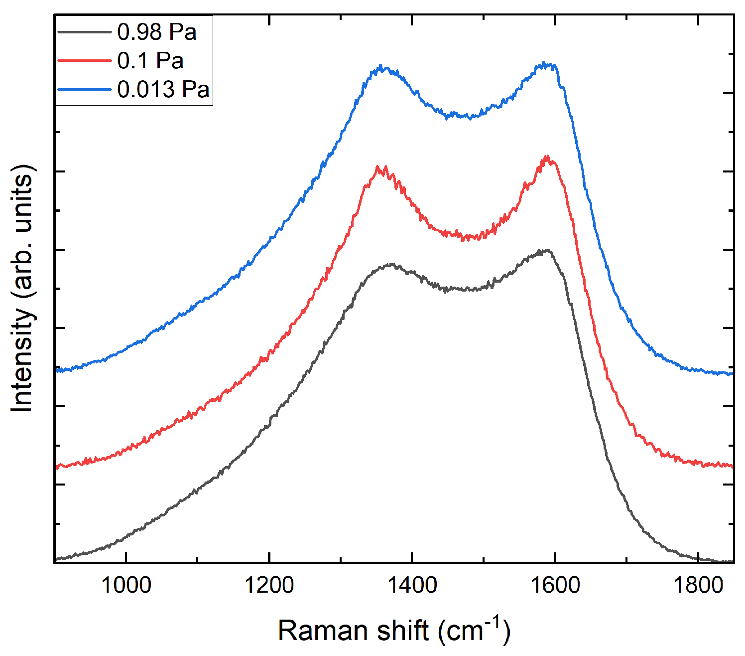
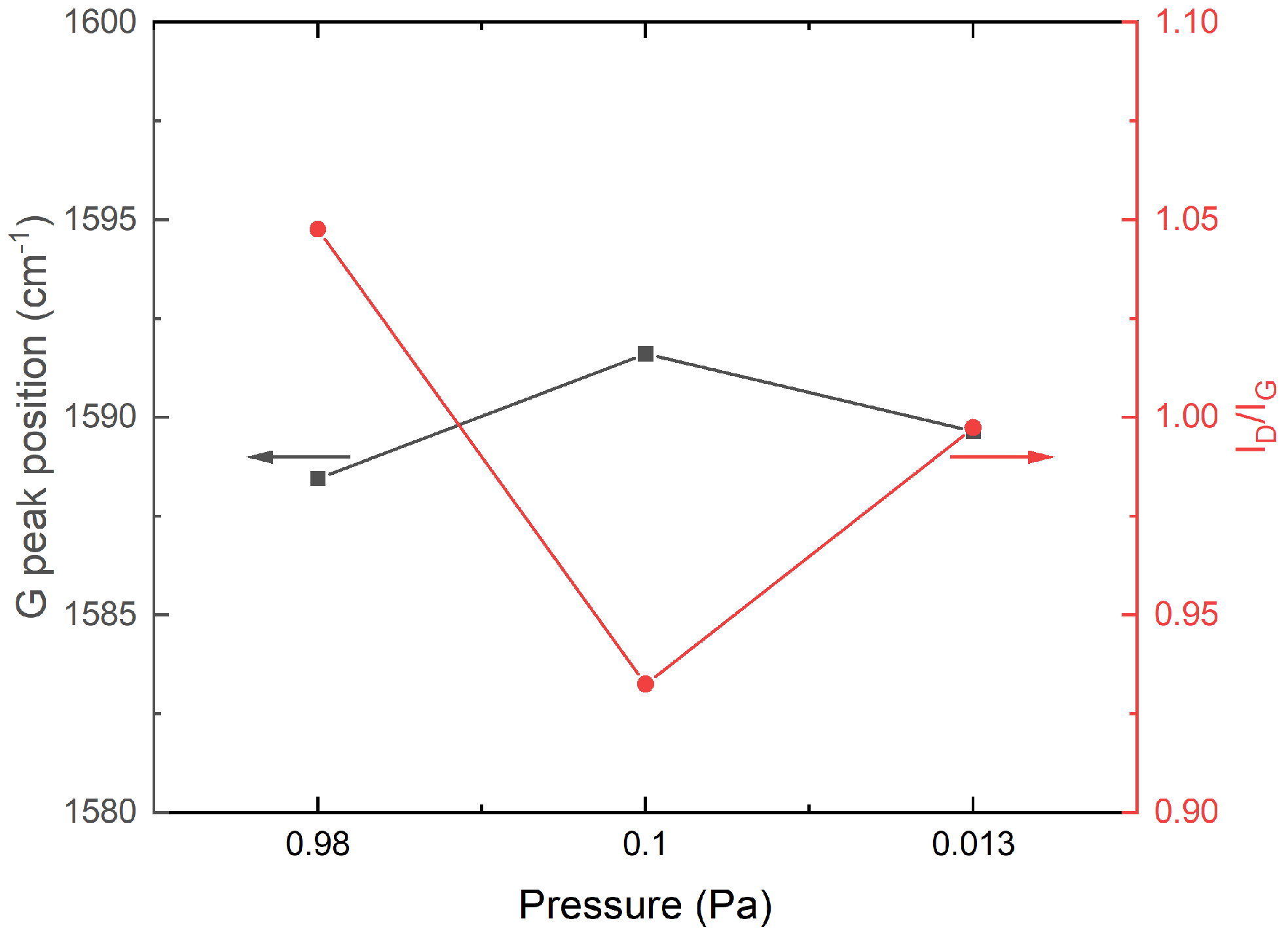
  • The evaluated Raman spectra indicate the structural differences between the carbon layer variants. Based on the characteristics I D / I G and G peak position, the carbon layer variants can be classified as highly sp2-bonded carbon.
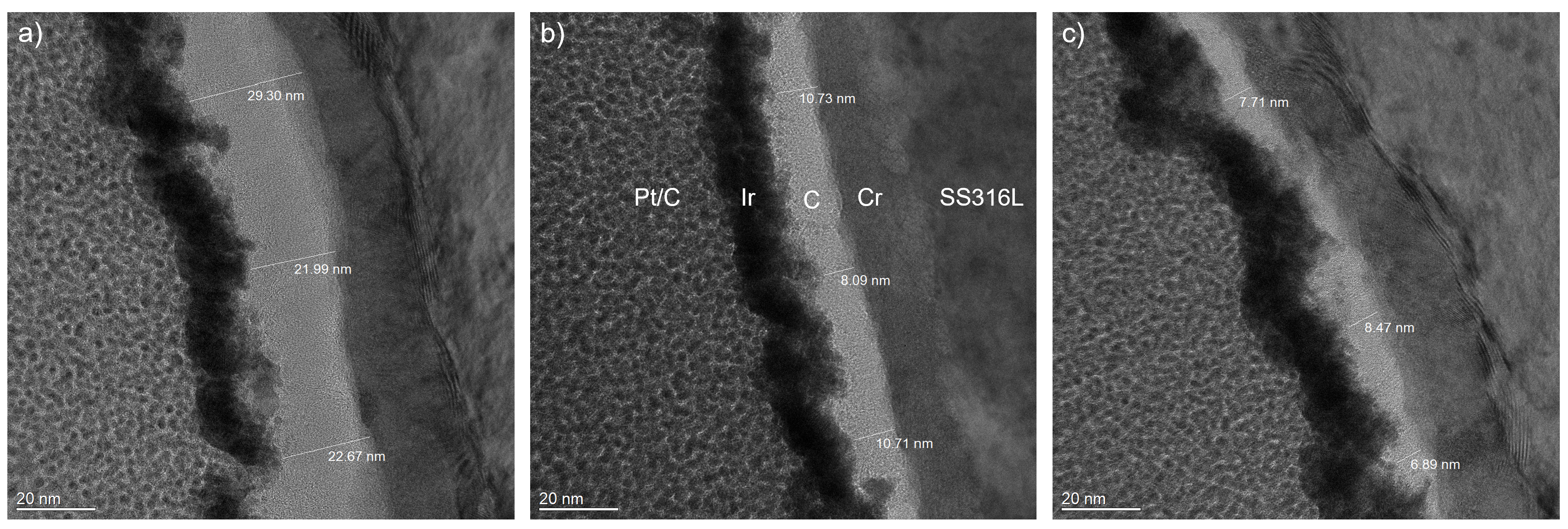
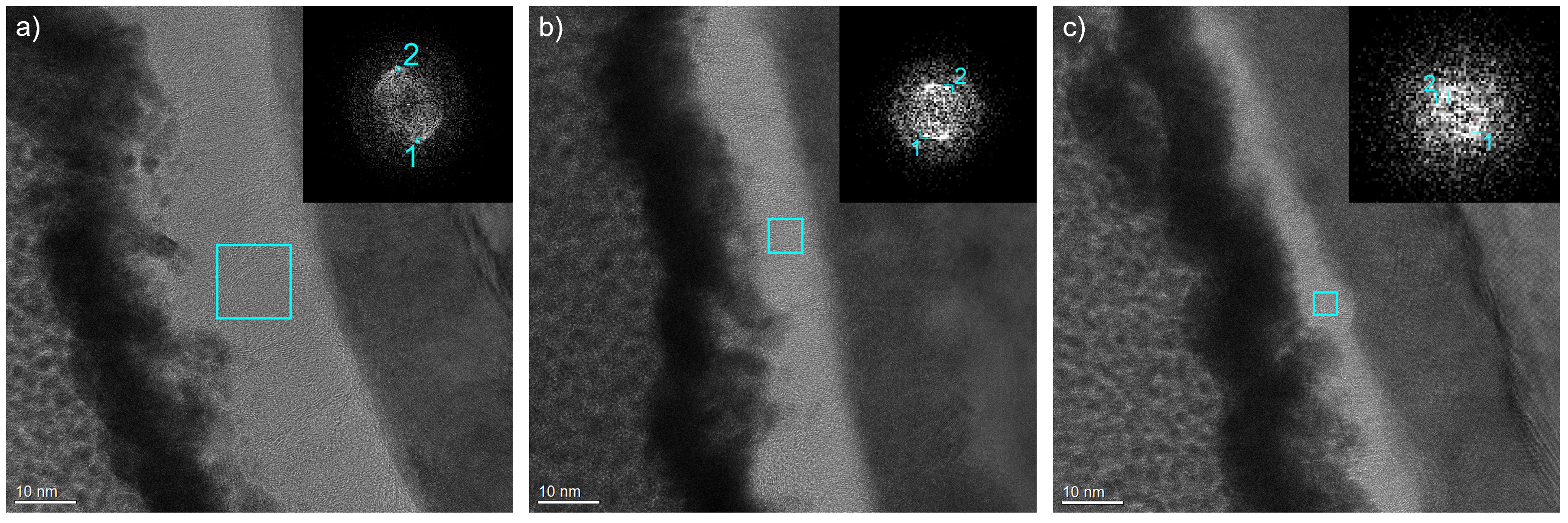
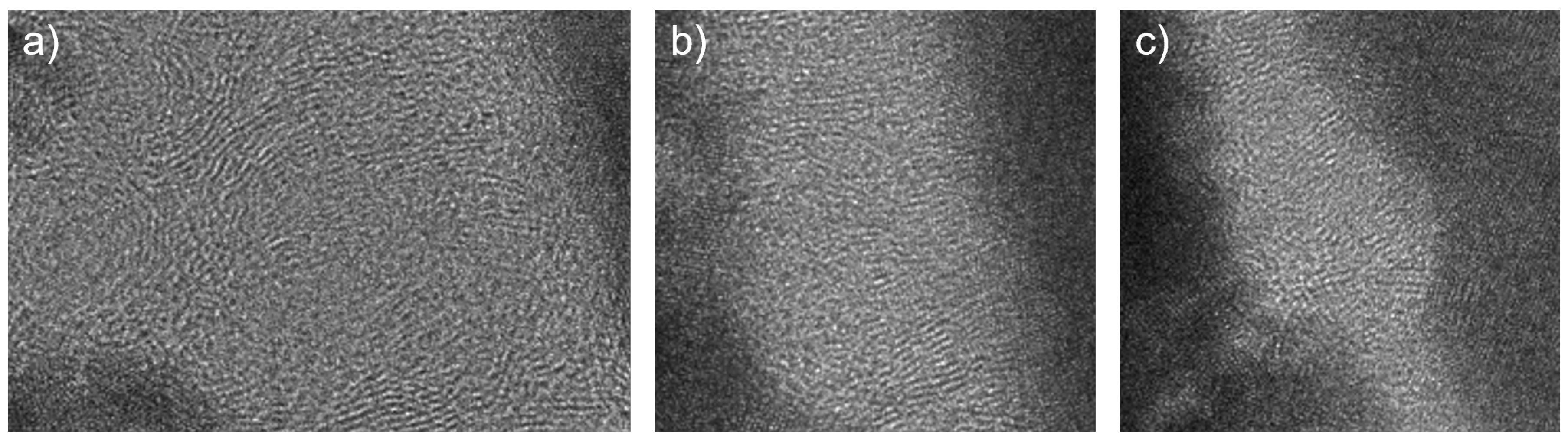
  • The investigated cross-sectional microstructures show mainly perpendicular graphitic layers, and the thickness of the carbon top layer increases with higher process pressure. For the carbon top layer deposited at 0.98 Pa, structural distortions, such as round-shaped features, can be observed, which agrees with the Raman results.
  • Both the contact resistance and electrochemical properties of the SS316L substrate are greatly improved.
  • The process pressure has a minor effect on the interfacial contact resistance, and there is also no apparent influence due to the thickness differences between the coating variants.
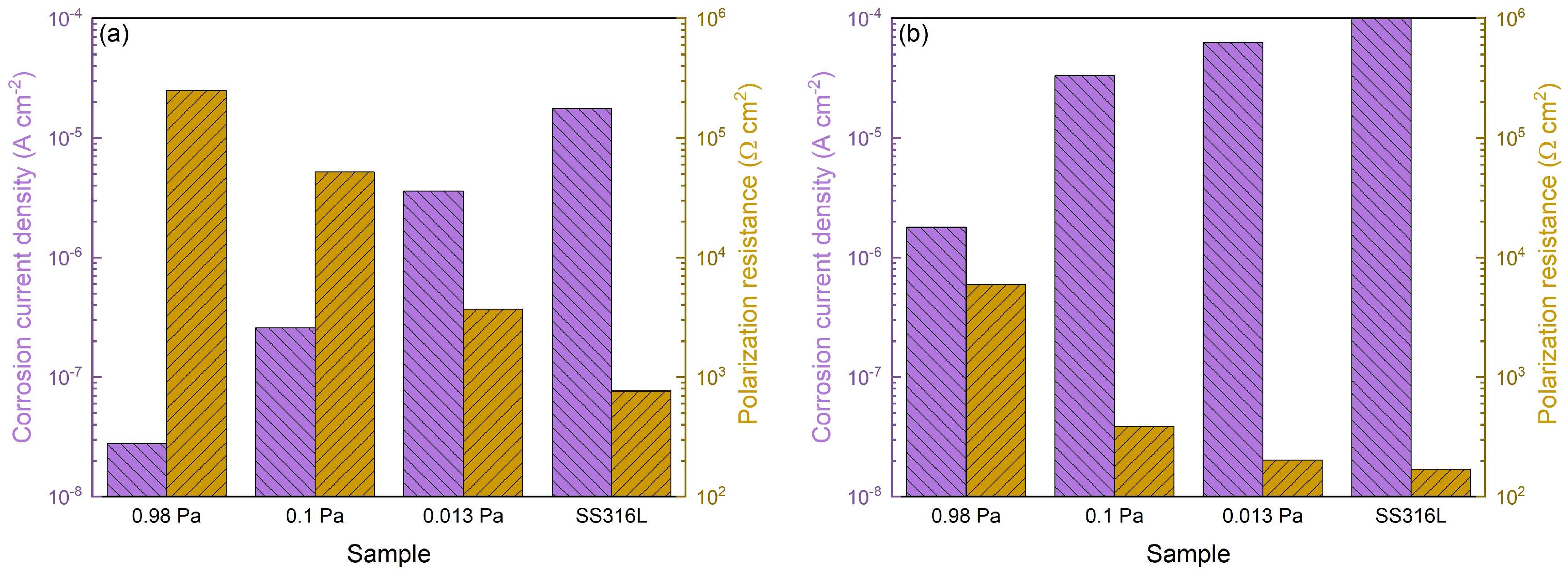
  • The corrosion resistance is considerably affected by the process pressure, and the 0.98 Pa sample exhibits the best corrosion resistance among the specimens, which is likely attributed to the different microstructure.
To summarize, the carbon-based coatings have superior low contact resistance and good corrosion resistance. Based on our results, the prepared coatings, especially the coating variant with a carbon top layer deposited at 0.98 Pa, are an excellent choice for the surface modification of stainless steel bipolar plates.

Author Contributions

M.S.: Conceptualization, Investigation, Data analysis and visualization, Writing (original draft, review and editing). M.G.: Conceptualization, Writing (original draft). T.R.: Conceptualization, Writing (original draft), Supervision. C.L.: Writing (original draft), Supervision. All authors have read and agreed to the published version of the manuscript.

Funding

This research was funded by the Fraunhofer internal research project HOKOME. The APC was funded by the Fraunhofer-Gesellschaft.

Data Availability Statement

Data are contained within the article.

Acknowledgments

The authors would like to acknowledge the support of D. Pohl, from the Dresden Center of Nanoanalysis, with the TEM imaging.

Conflicts of Interest

The authors declare no conflict of interest.

References

  1. Gröger, O.; Gasteiger, H.; Suchsland, J. Review-Electromobility: Batteries or Fuel Cells? J. Electrochem. Soc. 2015, 162, 2605–2622. [Google Scholar] [CrossRef]
  2. Alaswad, A.; Omran, A.; Sodre, J.R.; Wilberforce, T.; Pignatelli, G.; Dassisti, M.; Baroutaji, A.; Olabi, A.G. Technical and Commercial Challenges of Proton-Exchange Membrane (PEM) Fuel Cells. Energies 2021, 14, 012108. [Google Scholar] [CrossRef]
  3. Tawfik, H.; Hung, Y.; Mahajan, D. Metal bipolar plates for PEM fuel cell—A review. J. Power Sources 2007, 163, 755–767. [Google Scholar] [CrossRef]
  4. Mohr, P. Optimierung von Brennstoffzellen-Bipolarplatten für die Automobile Anwendung. Ph.D. Thesis, University Duisburg-Essen, Duisburg, Germany, 2018. [Google Scholar]
  5. United States Department of Energy. Hydrogen and Fuel Cell Technologies Office Multi-Year Research, Development, and Demonstration Plan; Technical Report; U.S. Department of Energy: Washington, DC, USA, 2017. [Google Scholar]
  6. Davies, D.; Adcock, P.; Turpin, M.; Rowen, S. Stainless steel as a bipolar plate material for solid polymer fuel cells. J. Power Sources 2000, 86, 237–242. [Google Scholar] [CrossRef]
  7. Song, Y.; Zhang, C.; Ling, C.; Han, M.; Yong, R.; Sun, D.; Chen, J. Review on current research of materials, fabrication and application for bipolar plate in proton exchange membrane fuel cell. Int. J. Hydrogen Energy 2020, 45, 29832–29847. [Google Scholar] [CrossRef]
  8. Yang, Y.; Guo, L.J.; Liu, H. Corrosion Characteristics of SS316l as Bipolar Plate Material in PEMFC Cathode Environments with Different Acidities. Int. J. Hydrogen Energy 2011, 36, 1654–1663. [Google Scholar] [CrossRef]
  9. Papadias, D.; Ahluwalia, R.; Thomson, J.; Meyer, H.; Brady, M.; Wang, H.; Turner, J.; Mukundan, R.; Borup, R. Degradation of SS316L bipolar plates in simulated fuel cell environment: Corrosion rate, barrier film formation kinetics and contact resistance. J. Power Sources 2015, 273, 1237–1249. [Google Scholar] [CrossRef]
  10. Mittal, V.O.; Kunz, H.R.; Fenton, J.M. Membrane Degradation Mechanisms in PEMFCs. J. Electrochem. Soc. 2007, 154, B652. [Google Scholar] [CrossRef]
  11. Liang, P.; Qiu, D.; Peng, L.; Yi, P.; Lai, X.; Ni, J. Contact resistance prediction of proton exchange membrane fuel cell considering fabrication characteristics of metallic bipolar plates. Energy Convers. Manag. 2018, 169, 334–344. [Google Scholar] [CrossRef]
  12. Liu, R.; Jia, Q.; Zhang, B.; Lai, Z.; Chen, L. Protective coatings for metal bipolar plates of fuel cells: A review. Int. J. Hydrogen Energy 2022, 47, 22915–22937. [Google Scholar] [CrossRef]
  13. Schultrich, B. Tetrahedrally Bonded Amorphous Carbon Films I, 1st ed.; Springer: Berlin/Heidelberg, Germany, 2018. [Google Scholar] [CrossRef]
  14. Yi, P.; Zhang, D.; Qiu, D.; Peng, L.; Lai, X. Carbon-based coatings for metallic bipolar plates used in proton exchange membrane fuel cells. Int. J. Hydrogen Energy 2019, 44, 6813–6843. [Google Scholar] [CrossRef]
  15. Yi, P.; Peng, L.; Feng, L.; Gan, P.; Lai, X. Performance of a proton exchange membrane fuel cell stack using conductive amorphous carbon-coated 304 stainless steel bipolar plates. J. Power Sources 2010, 195, 7061–7066. [Google Scholar] [CrossRef]
  16. Larijani, M.; Yari, M.; Afshar, A.; Jafarian, M.; Eshghabadi, M. A comparison of carbon coated and uncoated 316L stainless steel for using as bipolar plates in PEMFCs. J. Alloys Compd. 2011, 509, 7400–7404. [Google Scholar] [CrossRef]
  17. Husby, H.; Kongstein, O.; Oedegaard, A.; Seland, F. Carbon-polymer composite coatings for PEM fuel cell bipolar plates. Int. J. Hydrogen Energy 2014, 39, 951–957. [Google Scholar] [CrossRef]
  18. Bi, F.; Li, X.; Yi, P.; Hou, K.; Peng, L.; Lai, X. Characteristics of Amorphous Carbon Films to Resist High Potential Impact in PEMFCs Bipolar Plates for Automotive Application. Int. J. Hydrogen Energy 2017, 42, 14279–14289. [Google Scholar] [CrossRef]
  19. Lu, C.; Shi, F.; Jin, J.; Peng, X. Study on the Properties of Vertical Carbon Nanotube Films Grown on Stainless Steel Bipolar Plates. Materials 2019, 12, 899. [Google Scholar] [CrossRef]
  20. Park, J.H.; Wada, T.; Naruse, Y.; Hagio, T.; Kamimoto, Y.; Ryoichi, I. Electrodeposition of Ni-W/CNT Composite Plating and Its Potential as Coating for PEMFC Bipolar Plate. Coatings 2020, 10, 1095. [Google Scholar] [CrossRef]
  21. Asri, N.; Husaini, T.; Sulong, A.; Majlan, E.; Daud, W. Coating of stainless steel and titanium bipolar plates for anticorrosion in PEMFC: A review. Int. J. Hydrogen Energy 2019, 42, 9135–9148. [Google Scholar] [CrossRef]
  22. Xu, Z.; Qiu, D.; Yi, P.; Peng, L.; Lai, X. Towards mass applications: A review on the challenges and developments in metallic bipolar plates for PEMFC. Prog. Nat. Sci. Mater. Int. 2020, 30, 815–824. [Google Scholar] [CrossRef]
  23. Chauhan, S.; Ponkshe, S. A Review of Coated Metallic Bipolar Plates for Proton Exchange Membrane Fuel Cell PEMFC. In Proceedings of the WCX SAE World Congress Experience, Detroit, MI, USA, 5–7 April 2022. [Google Scholar] [CrossRef]
  24. Huang, Y. Corrosion Resistance, Interfacial Contact Resistance, and Hydrophobicity of 316L Stainless Steel Bipolar Plates Coated with TiN/Amorphous Carbon Double Layer under Different Carbon Target Currents. Coatings 2023, 13, 1494. [Google Scholar] [CrossRef]
  25. Vetter, J.; Mueller, J.; Erkens, G. Domino Platform: PVD Coaters for Arc Evaporation and High Current Pulsed Magnetron Sputtering. IOP Conf. Ser. Mater. Sci. Eng. 2012, 39, 012004. [Google Scholar] [CrossRef]
  26. Gudmundsson, J.T.; Anders, A.; von Keudell, A. Foundations of physical vapor deposition with plasma assistance. Plasma Sources Sci. Technol. 2022, 31, 083001. [Google Scholar] [CrossRef]
  27. Anders, A. A review comparing cathodic arcs and high power impulse magnetron sputtering (HiPIMS). Surf. Coatings Technol. 2014, 257, 308–325. [Google Scholar] [CrossRef]
  28. Ohring, M. Materials Science of Thin Films: Depositon and Structure, 2nd ed.; Elsevier: Amsterdam, The Netherlands, 2002. [Google Scholar] [CrossRef]
  29. Anders, A. A structure zone diagram including plasma-based deposition and ion etching. Thin Solid Film. 2010, 518, 4087–4090. [Google Scholar] [CrossRef]
  30. Steinhorst, M.; Giorgio, M.; Roch, T.; Leyens, C. Bias Voltage Dependency of Structural and Bipolar Plate-Related Properties of Cathodic Arc-Deposited Carbon-Based Coatings. Acs Appl. Mater. Interfaces 2023, 15, 51704–51712. [Google Scholar] [CrossRef] [PubMed]
  31. Yi, P.; Zhang, W.; Bi, F.; Peng, L.; Lai, X. Microstructure and Properties of a-C Films Deposited Under Different Argon Flow Rate on Stainless Steel Bipolar Plates for Proton Exchange Membrane Fuel Cells. J. Power Sources 2019, 410–411, 188–195. [Google Scholar] [CrossRef]
  32. Vetter, J. 60 years of DLC coatings: Historical highlights and technical review of cathodic arc processes to synthesize various DLC types, and their evolution for industrial applications. Surf. Coat. Technol. 2014, 257, 213–240. [Google Scholar] [CrossRef]
  33. Robertson, J. Diamond-like amorphous carbon. Mater. Sci. Eng. R Rep. 2002, 37, 129–281. [Google Scholar] [CrossRef]
  34. Ferrari, A.; Robertson, J. Raman spectroscopy of amorphous, nanostructured, diamond-like carbon, and nanodiamond. Philos. Trans. R. Soc. London Ser. A Math. Phys. Eng. Sci. 2004, 362, 2477–2512. [Google Scholar] [CrossRef]
  35. Ferrari, A.; Robertson, J. Interpretation of Raman spectra of disordered and amorphous carbon. Phys. Rev. B 2000, 61, 14095–14107. [Google Scholar] [CrossRef]
  36. Gregoire, J.M.; Lobovsky, M.B.; Heinz, M.F.; DiSalvo, F.J.; van Dover, R.B. Resputtering Phenomena and Determination of Composition in Codeposited Films. Phys. Rev. B 2007, 76, 195437. [Google Scholar] [CrossRef]
  37. Tritremmel, C. Comparison of Magnetron Sputtering and Arc Evaporation by Al-Cr-N Hard Coatings. Ph.D. Thesis, University of Leoben, Leoben, Austria, 2007. [Google Scholar]
  38. Su, Y.L.; Kao, W.H.; Chang, G.Y. Tribological, Anti-corrosion, and Electrical Conductivity Properties of CrCx Coatings Deposited on Stainless Steel 316L and Used as Metal Bipolar Plates for Fuel Cells. J. Mater. Eng. Perform. 2023, 32, 3739–3754. [Google Scholar] [CrossRef]
  39. Hamann, C.; Hamnett, A.; Vielstich, W. Electrochemistry, 2nd ed.; Wiley-VCH: Weinheim, Germany, 2007. [Google Scholar]
Figure 1. Raman spectra of the coated samples with a carbon top layer deposited at 0.98 Pa, 0.1 Pa and 0.013 Pa.
Coatings 13 01962 g001
Figure 2. Raman G peak position in grey and peak intensity ratio I D / I G in red depending on the process pressure during the carbon top layer deposition.
Coatings 13 01962 g002
Figure 3. Overview TEM images, including those of coated samples with a carbon top layer deposited at (a) 0.98 Pa, (b) 0.1 Pa and (c) 0.013 Pa.
Coatings 13 01962 g003
Figure 4. High-magnification TEM images of coated samples with a carbon top layer deposited at (a) 0.98 Pa, (b) 0.1 Pa and (c) 0.013 Pa. The insets present the diffraction patterns based on a fast Fourier transformation, and the numbers indicate the evaluated spots for the determination of the d-spacing values.
Coatings 13 01962 g004
Figure 5. Zoomed-in TEM images of coated samples with a carbon top layer deposited at (a) 0.98 Pa, (b) 0.1 Pa and (c) 0.013 Pa. Therefore, the indicated regions in Figure 4 were used.
Coatings 13 01962 g005
Figure 6. Interfacial contact resistance at a compaction force of 50 N cm−2 and 150 N cm−2 of the bare SS316L substrate and the coated samples with a carbon top layer deposited at 0.98 Pa, 0.1 Pa and 0.013 Pa.
Coatings 13 01962 g006
Figure 7. Polarization curves of the coated samples with a carbon top layer deposited at 0.98 Pa, 0.1 Pa and 0.013 Pa in 0.5 M H2SO4 at (a) room temperature and (b) 80 ° C. The electrolyte was bubbled with argon.
Coatings 13 01962 g007
Figure 8. Corrosion characteristics of the coated samples with a carbon top layer deposited at 0.98 Pa, 0.1 Pa and 0.013 Pa. The experimental conditions were 0.5 M H2SO4 at (a) room temperature and (b) 80 ° C bubbled with argon.
Coatings 13 01962 g008
Disclaimer/Publisher’s Note: The statements, opinions and data contained in all publications are solely those of the individual author(s) and contributor(s) and not of MDPI and/or the editor(s). MDPI and/or the editor(s) disclaim responsibility for any injury to people or property resulting from any ideas, methods, instructions or products referred to in the content.

