Article

The Influence of Lyophobicity and Lyophilicity of Film-Forming Systems on the Properties of Tin Oxide Films

1
Institute of Physics and Technology, Satbayev University, Ibragimov 11, Almaty 050013, Kazakhstan
2
Institute of Energy and Mechanical Engineering Named after A. Burkitbaeva, Satbayev University, Satpayev 22, Almaty 050000, Kazakhstan
*
Author to whom correspondence should be addressed.
Coatings 2023, 13(12), 1990; https://doi.org/10.3390/coatings13121990
Submission received: 13 October 2023 / Revised: 14 November 2023 / Accepted: 20 November 2023 / Published: 23 November 2023
(This article belongs to the Special Issue Recent Advances in the Development of Thin Films)

Abstract

:
In this work, the effects of lyophobicity and lyophilicity of film-forming systems on the properties of thin nanostructured films was studied. Systematic series of experiments were carried out with lyophilic film-forming systems: SnCl4/EtOH, SnCl4/EtOH/NH4F, SnCl4/EtOH/NH4OH and lyophobic systems: SnO2/EtOH and SnO2/EtOH/NH4F. Film growth mechanisms are determined depending on the type of film-forming system. The surface of the films was studied using a scanning electron microscope and an optical microscope. The spectrophotometric method is used to study the transmission spectra and the extinction coefficient. The surface resistance of the films was determined using the four-probe method. The quality factor and specific conductivity of the films are calculated. It was found that the addition of a fluorinating agent (NH4F) to a film-forming system containing SnO2 in the form of a dispersed phase does not lead to an increase in the specific conductivity of the films. X-ray diffraction analysis proved the incorporation of fluorine ions into the structure of the film obtained from the SnCl4/EtOH/NH4F system by the presence of SnOF2 peaks. In films obtained from SnO2/EtOH/NH4F systems, there are no SnOF2 peaks. In this case, ammonium fluoride crystallizes as a separate phase and decomposes into volatile compounds.

1. Introduction

SnO2 thin films possess exceptional properties, including a wide bandgap (Eg = 3.6 eV), n-type conductivity, transparency of more than 80% in the visible wavelength range, chemical stability, and others [1,2,3]. As a result, SnO2 has been widely used in various applications such as solar cells [4,5,6], gas sensors [7,8,9], transistors [10,11,12], optoelectronic devices, and transparent conductive electrodes [13,14,15]. SnO2 films are doped and modified in composition to meet the increasing demand for functional coatings. Both metallic particles [16,17] and non-metallic ions are used as doping additives. Of the non-metals, fluorine ions are prevalent [18,19,20,21,22,23]. The bandgap is reduced and the oxidation potential of holes is improved by doping the material with fluorine atoms [24,25]. Tin oxide films doped with fluorine and indium [26] are used in photocatalysis [27,28,29], perovskite solar cells [30,31,32], electrochemistry [33,34,35], and biosensors [36,37,38]. Great success in obtaining films of tin oxide doped with fluorine has been achieved using the sol-gel method. This method is based on the transition of film-forming systems into a gel. Gel formation can occur from both a lyophilic system and a lyophobic system. Considerable attention has been directed toward the investigation of lyophilic and lyophobic systems. In particular, thermohydrodynamics exhibit differences in lyophilic and lyophobic systems [39,40], and diverse interactions of a nanodroplet with a nanoprotrusion are observed [41]. The introduction of additives often leads to a change in the characteristics of film-forming systems, which affects the size of the particles obtained, the density and porosity of the films, the specific surface area, and the surface-to-volume ratio change. Positron annihilation spectroscopy is the most informative method for the study of porosity and free volume [42].
However, several questions persist when opting to use either a lyophilic or lyophobic system for acquiring sol-gel films. Specifically, what is the mechanism of film growth in a particular system? Can the growth of films be described using mathematical equations? How do additives affect one or both systems? Is the alloying element consistently incorporated into the film structure? Do the properties of the resulting films change equivalently upon the addition of additives to a lyophobic or lyophilic system?
In this work, it is shown that the film structure and its functional properties can differ significantly for lyophilic and lyophobic systems. This is because lyophilic systems incorporate an element from a dopant into the film composition, unlike lyophobic systems.

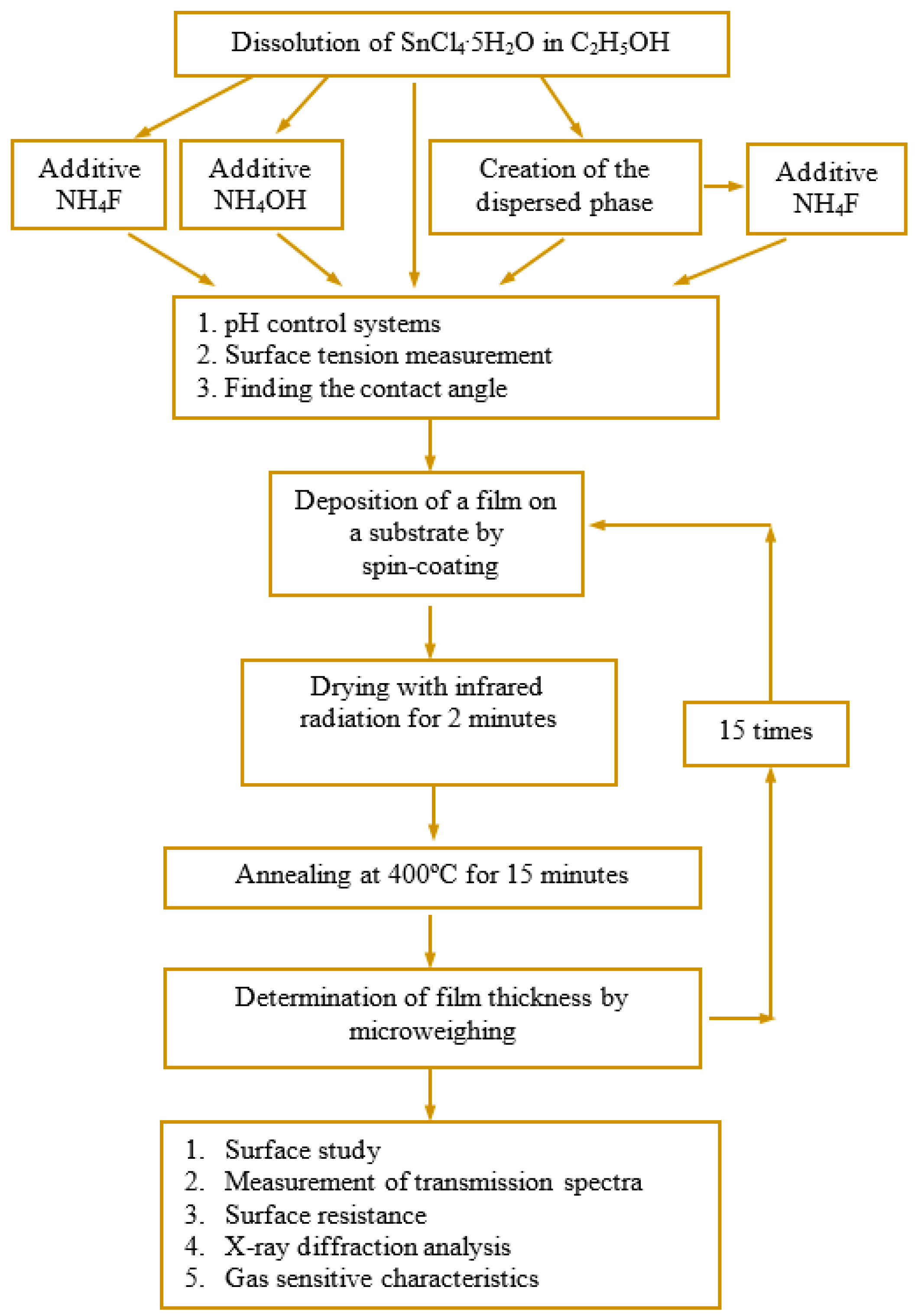
2. Materials and Methods

Film-forming systems were obtained from: tin tetrachloride crystalline hydrate SnCl4·5H2O (>98% pure grade), rectified alcohol, corresponding to State Standard [43], aqueous ammonia solution (>98% pure grade), and an NH4F dopant (>98% pure grade). The experimental procedure is shown in Figure 1.
Five film-forming systems were obtained:
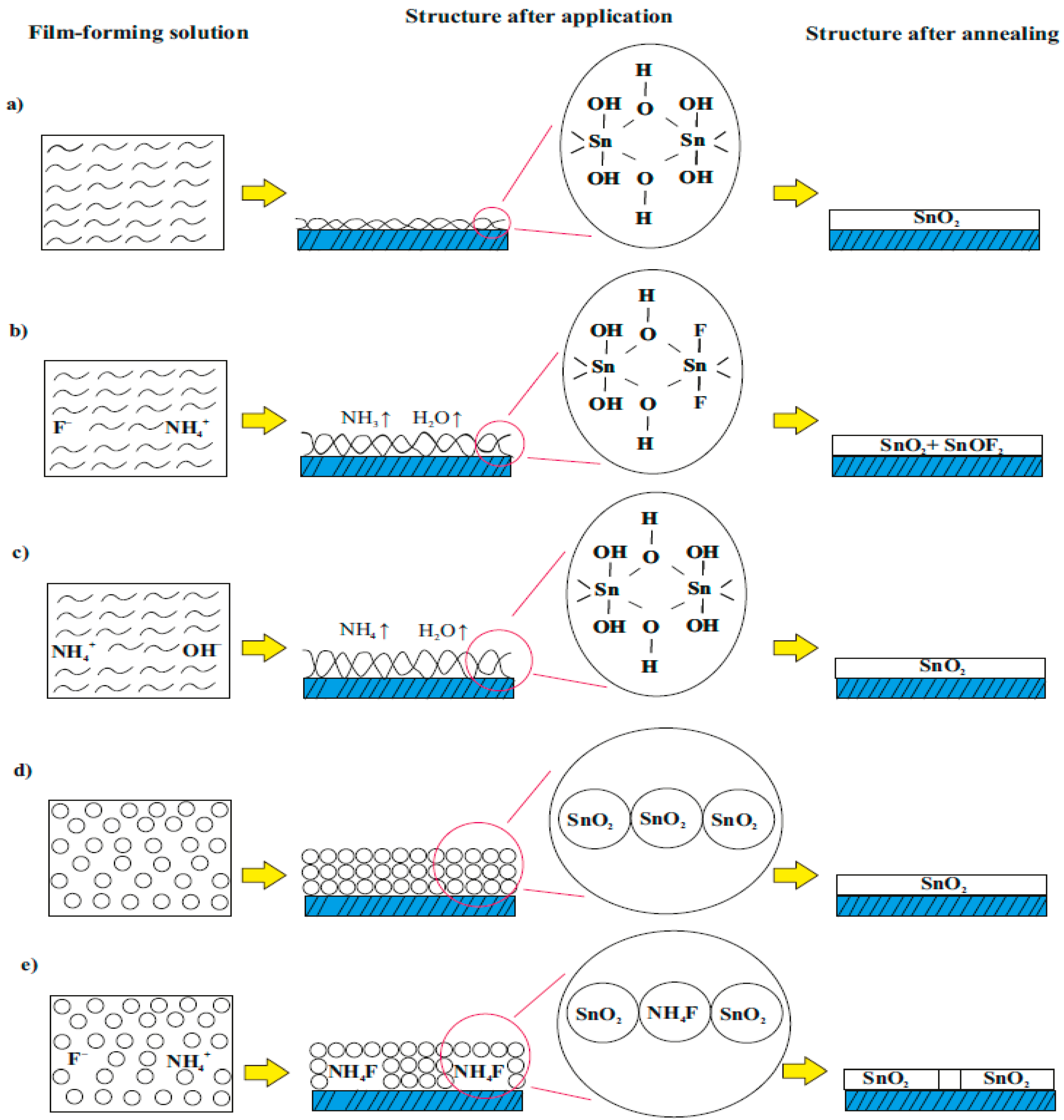
  • SnCl4/EtOH: SnCl4·5H2O was dissolved in ethanol. The concentration of tin ions in the system was 0.13 mol/L.
  • SnCl4/EtOH/NH4F: The fluorinating agent, NH4F, was added to the SnCl4/EtOH system. The ratio of tin ions to fluorine ions was 10/4. The NH4F crystals were dissolved after being stirred for 2 h at 140 rpm and concurrently heated to 35 °C.
  • SnCl4/EtOH/NH4OH: 20% alcohol solution of ammonia was added to the SnCl4/EtOH system until the pH level reached the same as that of the SnCl4/EtOH/NH4F system (pH = 1.80).
  • SnO2/EtOH: A concentrated aqueous ammonia solution was added to the SnCl4/EtOH system until the complete precipitation of tin hydroxide. The solvent and water associated with tin oxide was removed by heating to 100 °C and stirring at a speed of 160 rpm. After drying, a white powder was obtained. Ethanol was used to fill the tin oxide powder to obtain a solution with a tin oxide concentration of 0.13 mol/L. The vessel’s contents were stirred at a speed of 100 rpm without any heating until the precipitate transitioned into solution. The procedure lasted for 4 h.
  • Film-forming system containing SnO2 in the form of a dispersed phase with the addition of NH4F (SnO2/EtOH/NH4F): crystals of ammonium fluoride were added to the system containing SnO2 in the form of a dispersed phase. The ratio of tin ions to fluorine ions was 10/4.
The pH level of the systems was assessed using a pH meter known as “pH-150 M”. The surface tension was determined through the stalagmometric method, and the spreading drop method was applied to study the wetting angle of film-forming systems with the substrate surface.
Film-forming systems were applied onto glass slides using spin-coating. The rotation speed was 3000 rpm for 4 s. Infrared radiation was used for 2 min at 80 °C to dry the samples. Subsequently, the sample was annealed in a muffle furnace for 15 min at 400 °C. After cooling the sample, the deposition process was repeated. A total of 15 layers were applied.
The thickness of the film was determined through the microbalance approach. The JSM-6490LA, JEOL analytical scanning electron microscope, and MPE-11 optical microscope were utilized to study the surface structure of the obtained SnO2 films. The transmission and absorption spectra were measured on a UNICO spectrophotometer, while the surface resistance was quantified using the four-probe method. X-ray diffraction spectra were recorded on a DRON-6 diffractometer to complete the analysis. The study investigated the sensitivity to ethanol vapour using an experimental apparatus capable of maintaining the working chamber’s temperature with an accuracy of at least ±2 °C, ranging from room temperature to 450 °C.

3. Results and Discussion

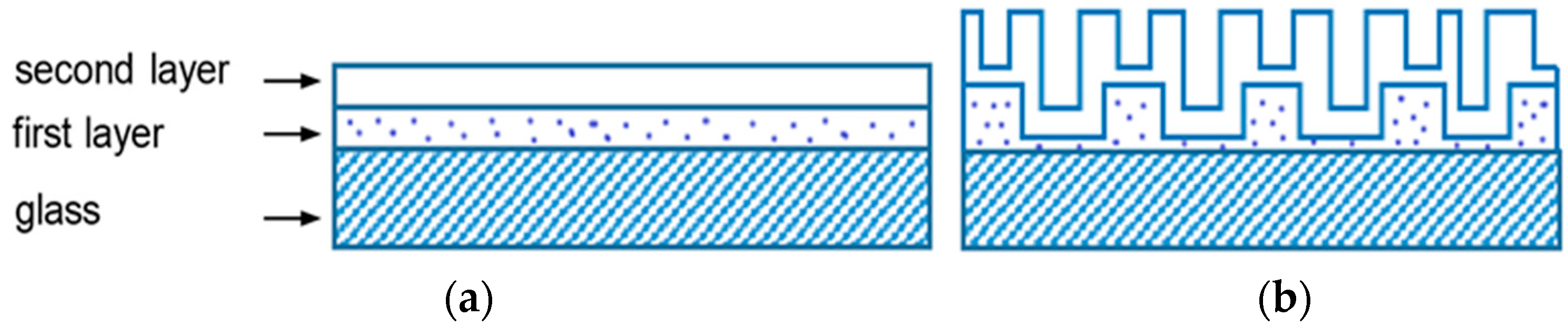
3.1. Formation of Films
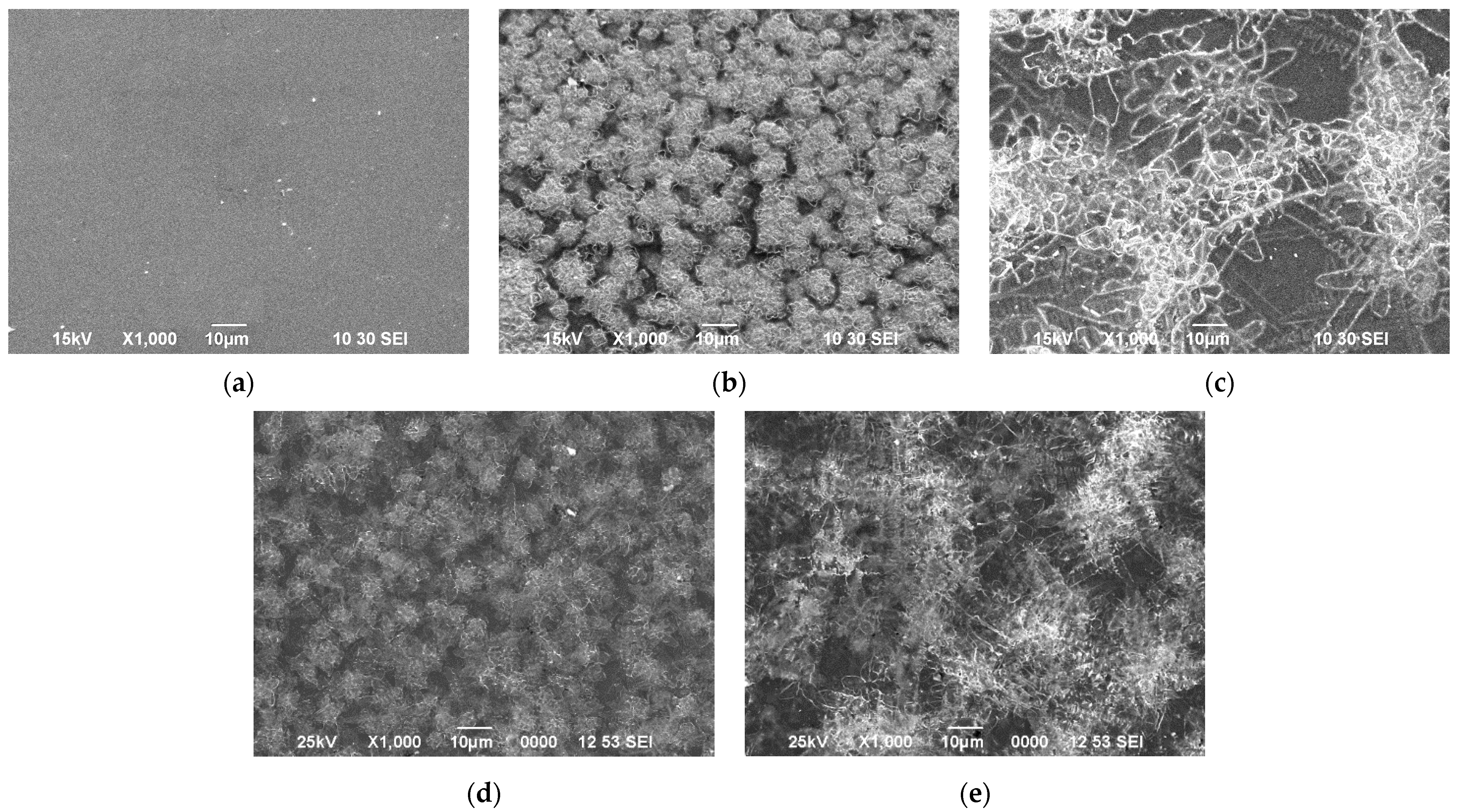
Control of the acidity of the film-forming systems indicated that the SnCl4/EtOH system has a pH of 0.18. The addition of NH4F significantly changes this value to pH 1.80. The resulting SnCl4/EtOH/NH4F system has an acidity close to that of Sn(OH)4 formation (pH 2.0), which can lead to a change in the film structure. In order to accurately interpret subsequent measurements and detect the effects of fluorine ions on the properties of the obtained films, the SnCl4/EtOH/NH4OH system with pH = 1.80 was made. The pH level of film-forming systems that contained SnO2 in a dispersed phase was 3.62. With the addition of NH4F, the pH level was 3.58. The surface tension of all colloidal systems was 21.55 × 10³ ± 0.05 × 10³ N/m. The contact angle of wetting on the glass substrate was found to be close to zero for all systems, demonstrating that the surface was sufficiently wettable to produce homogeneous layers via spin-coating.
The change in sample mass as the film was deposited on the substrate was measured after each layer. From this data the variation in film thickness was calculated. The results obtained are shown in Figure 2.
Figure 2 illustrates the linear correlation between the number of deposited layers and the film thickness, as determined by the micro-weighting technique, in the SnCl4/EtOH film-forming system.
To obtain a more accurate assessment of how the estimated film thickness varies with the number of layers applied, we will use the least squares method of mathematical analysis. The fundamental principle of which can be expressed by the following equation:
i e i 2 = i ( y i f i x ) 2   m i n
where ei is the deviation of the i-th experimental value from the corresponding value of the approximating function, yi is the experimental value, and fi(x) is the approximating function. The value of the approximation reliability is determined by the formula:
R 2 = 1 i = 1 n ( y i f x i ) 2 i = 1 n y i 2 ( i = 1 n y i ) 2 n
where R2 is the value of approximation confidence. Approximation functions describing the change in film thickness on the number of applied layers, and the approximation confidence value are shown in Table 1.
All functions have an approximation confidence value greater than 0.9; therefore, the change in film thickness depending on the number of deposited layers for the chosen film-forming systems was described accurately. Table 1 illustrates that for the SnCl4/EtOH film-forming system, the linear function provides a high confidence description of the change in film thickness as the number of layers deposited increases. The thickness of the films is quadratically dependent on the number of layers in other film-forming systems. This indicates that with each subsequent layer, the mass change is greater than the previous one. This is possible in the case of the formation of “uneven” porous layers, when each subsequent layer fills the pores of the previous one and forms its own. This is shown schematically in Figure 3.
After applying 15 layers (Figure 1), the thickness of the films obtained from film-forming systems was: 250 ± 7 nm for SnCl4/EtOH; 152 ± 7 nm for SnCl4/EtOH/NH4F; 193 ± 7 nm for SnCl4/EtOH/NH4OH; 60 ± 7 nm for SnO2/EtOH; and 90 ± 7 nm for SnO2/EtOH/NH4F.
The films obtained from the SnCl4/EtOH lyophilic film-forming system exhibit superior adhesion to both the substrate and other layers due to their greater thickness. Films obtained from lyophobic film-forming systems containing SnO2 in the form of a dispersed phase have the smallest thickness. This highlights their lower adhesion to the glass substrate and other layers.
Thus, the films grown from the SnCl4/EtOH film-forming system proceed according to the Frank–van der Merwe layer-by-layer growth mechanism. The growth of films obtained from a film-forming system containing SnO2 in the form of a dispersed phase was carried out according to the Volmer–Weber island growth mechanism. And the growth of films with additives is carried out using the Stransky–Krystanov layer-by-layer-plus-island growth mechanism.

3.2. Film Structure

SEM images of the film surfaces investigated are illustrated in Figure 4. Observing Figure 4a, it is evident that films produced from the SnCl4/EtOH lyophilic system exhibit a smoother surface compared to other films. The crystallization process in films transpires on the substrate’s heated surface as HCl molecules evaporate. In doing so, HCl molecules hinder the formation of Sn(OH)4, as expressed in the chemical reaction:
SnCl4 + 4H2O → Sn(OH)4 + 4HCl.
The SEM images in Figure 4b,c reveal that the films possess diverse dendritic structures [44,45]. The development of dendritic structure is caused by a change in the acidity of film-forming systems due to the introduction of NH4F and NH4OH. Accelerated crystallization occurs from nonequilibrium conditions [46,47,48]. The introduction of NH4OH into the system not only leads to a change in acidity, but also adds functional OH ions. This leads to the growth of dendritic axes of the first order (see Figure 4c). SEM images in Figure 4d,f depict films prepared from lyophobic systems. We observe dendritic structures up to 10 μm in size on the surface, which are grains formed under accelerated crystallization conditions (see Figure 4d). Figure 4e shows agglomerates formed from SnO2 grains combined with an NH4F additive.

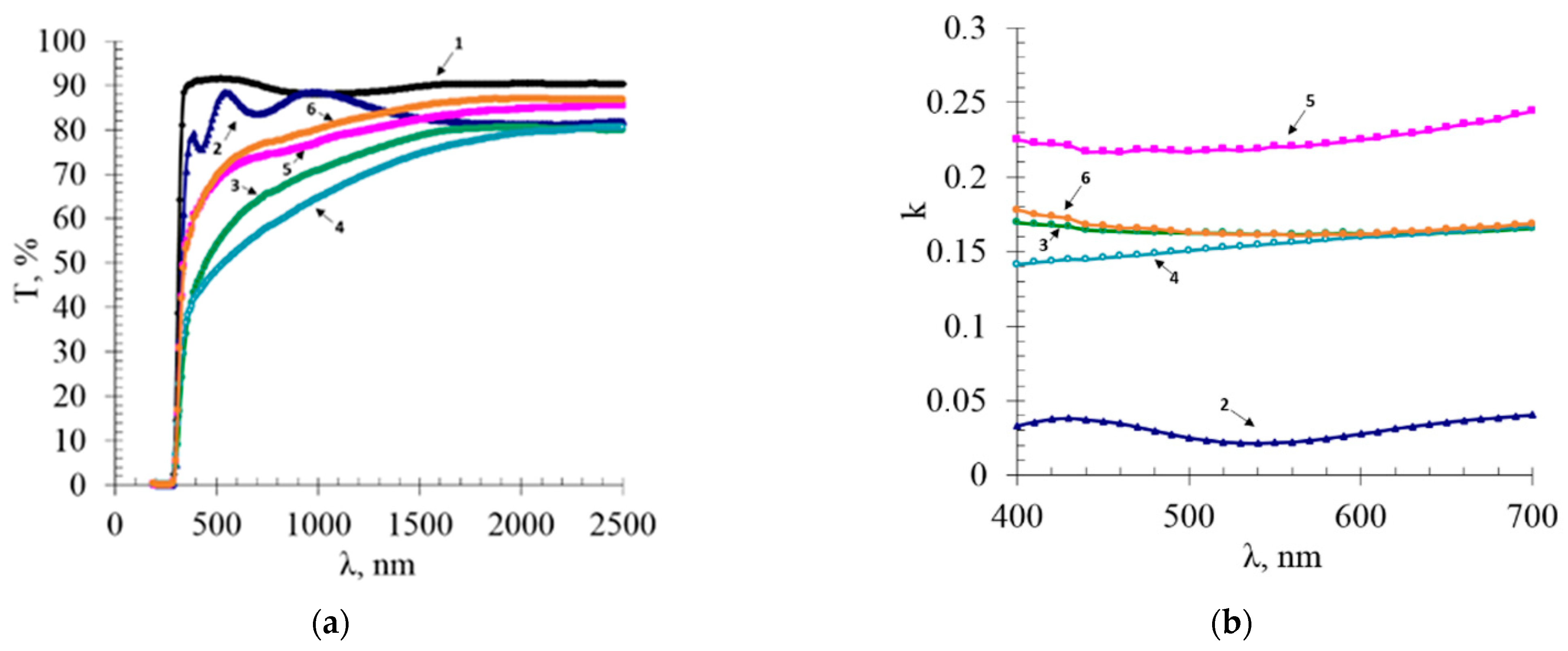
3.3. Optical Spectra and Surface Resistance

Figure 5 shows the transmission spectra of the films under study. The transmittance of the glass substrate is 88%–91% in the wavelength range from 340 nm to 2500 nm (curve 1 in Figure 5a).
For films with dendritic structures, the transmittance increases with increasing wavelength. For the purpose of considering the variation in film thicknesses, we use the “extinction coefficient” parameter which is computed as follows [49,50]:
α = 1 d · ln I 0 I .
Using the equation
α = 4 π · k λ
we obtained an expression for the extinction coefficient:
k = α · λ 4 π = 1 d · ln I 0 I · λ 4 π ,
where I0 is the intensity of incident light, I is the intensity of light transmitted through a layer with thickness d, α is the absorption index of the medium, and k is the extinction coefficient.
The extinction coefficient of the glass substrate is about 10−5 and aligns with the abscissa axis. In the selected wavelength range (curve 2 in Figure 5b), the film obtained from the SnCl4/EtOH film-forming system displays an extinction coefficient of 0.021–0.038. The extinction coefficients of films formed from the film-forming systems SnCl4/EtOH/NH4F, SnCl4/EtOH/NH4OH, and SnO2 dispersed in NH4F coincide with one another when wavelengths greater than 600 nm. The film obtained from the system containing SnO2 in a dispersed phase displays the highest extinction coefficient.
The transmission spectra of the films from the SnCl4/EtOH film-forming system illustrate interference peaks, observed in the case of plane-parallel films as a consequence of light interference reflected by two film surfaces [51,52]. The interference pattern relies on the phase difference of the propagating waves, expressed by the following conditions transmitted through light:
  • for minimum:
    2 d n 1 n 21 2 s i n 2 α = m λ .
  • for maximum:
    2 d n 1 n 21 2 s i n 2 α = 2 m 1 λ 2 .
As the beam was directed perpendicular to the surface, we can determine that the angle α = 0° => sin2α = 0. Assuming the refractive index of air as unity (n1 = 1), we obtain the minimum value:
2 d n 21 = m λ .
for maximum:
2 d n 21 = 2 m 1 λ 2 .
We have three extremes, two of which were lows and one was a high. After substituting the experimental values of λ at the extremum point, we solved a system of three equations with two unknowns, and upon performing the calculations, we found that d is equal to 313 ± 18 nm, and n = 2.03. The variation between the film thickness obtained by micro-balancing and the thickness calculated from the transmission spectra was attributed to the use of cassiterite density (7 g/cm3) in the calculations. Based on the difference in thickness values, we find the actual density of the film, which is 5.59 g/cm3.
The condition for interference peaks to appear is not met in other films.
One of the areas of application for films based on tin oxide is transparent conductive coatings. In this case, the considered transmittance and surface resistance are important. To determine the quality of the obtained films, a parameter known as the quality factor is used. It is determined using the Haacke relation [53,54]:
Φ = ( T / 100 ) 10 / R s h ,
where Φ is the quality factor, and T and Rsh are the transmission coefficients and surface resistance of the film, respectively. The average transmittance for the visible wavelength range was taken when calculating the quality factor.
For a correct assessment of the contribution of doping additives to the conductivity of the films, calculations of resistivity and conductivity were made. Resistivity is related to surface resistance and film thickness by the relationship:
ρ =   R s h d
where ρ is the resistivity, Rsh is the surface resistance, and d is the film thickness. Specific conductivity is the reciprocal of resistivity and is equal to 1/ρ. Surface resistance measurement data and calculation results are shown in Table 2.
Specific conductivity depends on the number and mobility of charge carriers:
1 / ρ = e n e μ e + e n h μ h ,
where e is the electron charge, ne is the number of electrons, μe is the electron mobility, nh is the number of holes, and µh is the hole mobility.
Since thin films of tin dioxide are n-type semiconductors and have a higher concentration of electrons than holes, the second term on the right side of Equation (13) is usually neglected. This equation takes the form [53] at a good approximation:
1 / ρ = e n e μ e .
According to the equation above, the conductivity (1/ρ) is expected to be influenced by ne and μe. Table 2 shows that the addition of NH4F to the SnCl4/EtOH/NH4F film-forming system leads to a several-fold increase in specific conductivity. This confirms the presence of fluorine ions as additional sources of free charge carriers in the films [55]. The addition of an aqueous ammonia solution to the SnCl4/EtOH/NH4OH film-forming system also led to an increase in the specific conductivity. Apparently, due to an unshared electron pair in the nitrogen atom. The addition of NH4F to the film-forming system containing SnO2 in the form of a dispersed phase did not lead to an increase in the specific electrical conductivity, but even slightly decreased it.
The answer to this phenomenon was found in the study of films in an optical microscope. Figure 6 shows the surface of films obtained from a film-forming system containing SnO2/EtOH and SnO2/EtOH/NH4F.
Figure 6a shows the dense structural connection between particles in the suspension. The calculated small thickness of the films led to the assumption that the adhesion of the films to the glass substrate reduced in comparison with those obtained from the SnCl4/EtOH, SnCl4/EtOH/NH4F, and SnCl4/EtOH/NH4OH film-forming systems. However, as can be seen from Figure 6a the film is uniform over the entire surface and there are no areas of the substrate not covered by the film. The minimal thickness of the film can be attributed to the low adhesion forces between the particles within the dispersed phase of the film-forming system. Figure 6b shows the surface of films obtained from a film-forming system containing SnO2 in the form of a dispersed phase with the addition of ammonium fluoride. In this area, one can observe depressions in the form of large dendritic structures, the dimensions of which reach 100 μm along the first-order axes.
Based on the analysis of Figure 6b, it can be assumed that the addition of ammonium fluoride to a film-forming system containing SnO2 in the form of a dispersed phase does not lead to a uniform distribution of the fluorinating agent in the film volume. This leads to the formation of separate SnO2 and NH4F phases.
Indeed, NH4F forms colorless crystals, which, upon heating, decompose in two stages [56]:
1-st stage. At 167 °C, ammonium fluoride decomposes into gaseous ammonia (NH3) and ammonium hydrofluoride (NH4HF2) according to the reaction:
>167 °C
2NH4F → NH4(HF2) + NH3↑.
2-nd stage. At 238 °C, ammonium hydrofluoride decomposes into gaseous ammonia (NH3) and gaseous hydrogen fluoride (HF) according to the reaction:
>238 °C
NH4(HF2) → NH3↑ + 2HF↑.
Considering that the films were annealed at 400 °C, the NH4F dendritic structures formed during drying decomposed into gaseous compounds. Instead of ammonium fluoride, voids formed after annealing. That is, defects that reduce the mean free path and, consequently, the mobility of charge carriers. The mobility of charge carriers is related to the mean free path by the expression:
μ = q m · t a v = q m · l a v V T ,
where q is the electron charge, m is the effective electron mass, tav is the mean free path of an electron between two successive collisions with defects in the crystal lattice, lav is the electron mean free path, and VT is the thermal velocity.
Thus, the addition of NH4F into a film-forming system containing SnO2 in the form of a dispersed phase leads to a decrease in the specific conductivity. Due to the formation of a separate NH4F phase, which decomposes into volatile compounds, forming voids in the film, which reduce the mean free path of charge carriers. X-ray diffraction analysis confirmed the presence of fluorine ions in the films obtained from the SnCl4/EtOH/NH4F film-forming systems. The X-ray patterns are shown in Figure 7.
The X-ray patterns (Figure 7) demonstrate that the films comprised SnO2 crystallites. On the X-ray diffraction pattern of the film obtained from the film-forming system SnCl4/EtOH/NH4F, SnOF2 peaks are observed, which indicates the successful incorporation of tin ions into the film structure. The absence of NH4F peaks in the X-ray diffraction pattern of films obtained from a film-forming system containing SnO2 in the form of a dispersed phase with the addition of ammonium fluoride confirms the assumption that ammonium fluoride crystallites decompose.
The average crystallite size (D) was determined from the broadening of X-ray lines using the Scherrer formula [57]:
D = ()/(βcosθ)
where k is the Scherrer constant, usually taken as 0.9, but its value strongly depends on the shape of the crystallites [58], λ is the X-ray wavelength, θ is the Bragg diffraction angle, and β is the diffraction line broadening measured at half its maximum intensity (rad). Table 3 shows the calculation results.
As can be seen from Table 3, the size of crystallites in films ranges from 3.5 nm to 6.3 nm. Thus, the formation of films can be represented as a diagram shown in Figure 8. Lyophilic film-forming systems (Figure 8a–c), after application to substrates, form a layer of tin hydroxide, in the form of α-form.
When NH4F is added into the lyophilic system, SnOF2 is formed. Film annealing leads to the formation of nanocrystalline SnO2. Lyophobic film-forming systems (Figure 8d,e) form films from already formed SnO2 particles. The addition of NH4F to the lyophobic system does not lead to the formation of SnOF2. Crystallization of NH4F occurs, which decomposes into volatile compounds, leaving voids in the film.

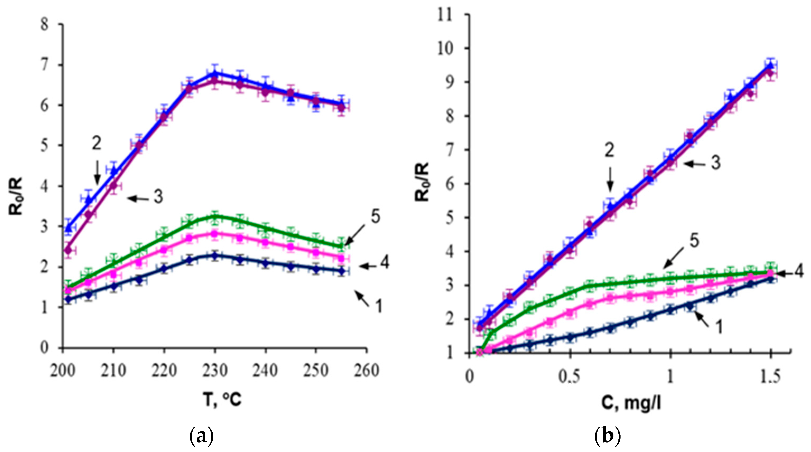
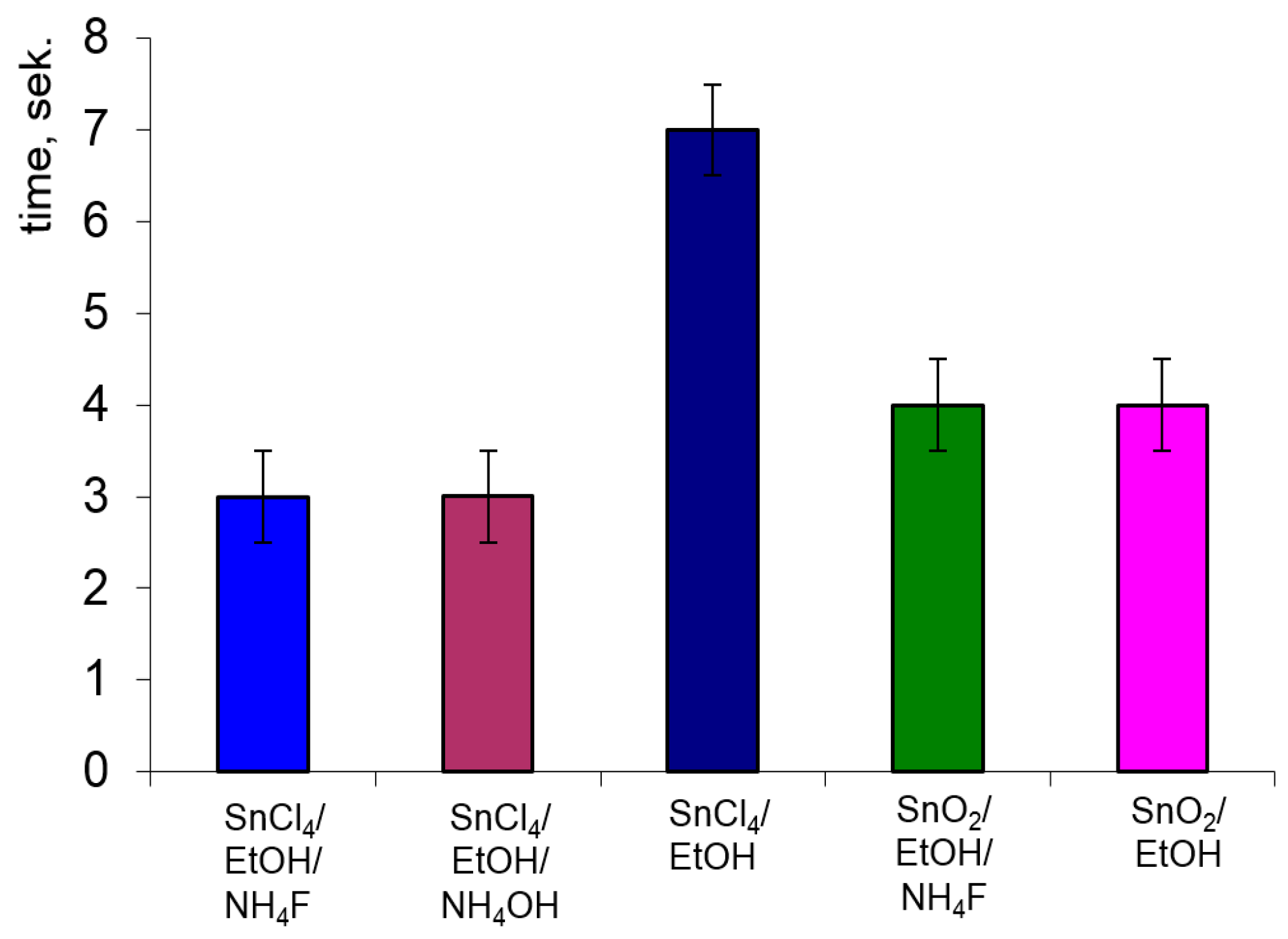
3.4. Sensitivity to Ethanol

In terms of electronic structure, SnO2 is a Lewis acid because it can accept a lone pair of electrons in its unfilled 5s25p2 orbital, while ethanol vapors (C2H5OH) can be Lewis bases because they include an OH group. Thus, the acid–base interaction can be responsible for the strong adsorption of ethanol vapor on SnO2. Upon adsorption, alcohol molecules tend to dissociate into an H atom to form a surface alkoxide, a surface hydroxyl, and the former tends to further convert to an aldehyde or ketone [59]. It is generally accepted that adsorbed oxygen (presumably Oads) or even surface lattice oxygen (O2−late) takes part in the oxidation of organic molecules. Electrons are returned to SnO2, and resistance decreases when oxidation occurs [60]. The interaction between the analyzed gas and the oxygen present on the surface of the tin oxide film largely determines its response to gas. Sensitivity properties are consequently significantly influenced by morphology, surface area, and any defective states. Additionally, the operational temperature has a strong impact on the characteristics of metal oxide-based gas sensors [61].
Figure 9a shows the temperature dependence of the sensitivity of thin SnO2 films to ethanol vapor (1 mg/L). Among all studied films, the highest sensitivity is obtained at a substrate temperature of 230 °C.
Since, at temperatures below 100 °C, the main adsorbed forms of oxygen are O2−, and at temperatures < 300 °C—O, then, in our case, the interaction of ethanol vapor with the film, leading to a decrease in resistance, occurs according to the reaction [62]:
C2H5OH(gas) + 6O(ads) → 3H2O + 2CO2 + 6e
(T < 300 °C).
The experiment investigated film sensitivity to varying concentrations of ethanol vapours at 230 °C and is illustrated in Figure 9b. The dendritic structured films demonstrated higher ethanol sensitivity than films produced from the SnCl4/EtOH film-forming system. The increase in sensitivity correlates with the increase in surface area available for adsorption-desorption reactions. The sensitivity of films obtained from film-forming systems containing SnO2 in the form of a dispersed phase changes little at an ethanol vapor concentration of more than 0.6 mg/L. This is attributed to the low mass of the film and, as a result, a restricted amount of reactive adsorbed oxygen ions. There is a “saturation” of active centers.
The sensitivities of films obtained from the SnCl4/EtOH/NH4F and SnCl4/EtOH/NH4OH film-forming systems differ within the measurement accuracy and are linear in the selected concentration range. These films exhibit sensitivity to low-concentration ethanol vapor (0.05 mg/L (26 ppm)).
The response time is an important characteristics of gas sensors, and Figure 10 illustrates the response time values of the studied films when exposed to ethanol vapor at a concentration of 1 mg/L.
Figure 10 shows that the films synthesized from the SnCl4/EtOH/NH4F and SnCl4/EtOH/NH4OH film-forming systems have the shortest response time. Reducing the response time by a factor of 2 when NH4F and NH4OH are added to the film-forming system is associated with the formation of a developed specific surface area of the film.
Consequently, the films produced from the SnCl4/EtOH/NH4F and SnCl4/EtOH/NH4OH film-forming systems possess high sensitivity to ethanol vapour and a short response time.

4. Conclusions

The film growth from the lyophilic system (SnCl4/EtOH) proceeded according to the layer-by-layer Frank–van der Merwe growth mechanism. The growth of films from the lyophobic system (SnO2/EtOH) was carried out according to the Volmer–Weber island growth mechanism. And the growth of films with additives was carried out according to the Stranski–Krystanov layer-by-island growth mechanism.
Films obtained from the lyophilic system have smoother surfaces than those obtained from the lyophobic system. Foams from the lyophobic system have a dendritic structure.
Adding NH4F to the lyophilic system increases film conductivity, while it has no effect on specific conductivity in a lyophobic system.
The addition of ammonium fluoride to the lyophilic system leads to the incorporation of fluorine ions into the film structure, resulting in the formation of SnOF2 crystallites. Meanwhile, in the lyophobic mode, separate phases of SnO2 and NH4F are formed. Upon annealing, NH4F decomposes into volatile compounds, leaving behind voids.
The films obtained from the SnCl4/EtOH/NH4F and SnCl4/EtOH/NH4OH film-forming systems show equivalent sensitivity within the limits of measurement accuracy and linearity within the selected concentration range. A sensitivity to low concentrations of ethanol vapour (0.05 mg/L (26 ppm)) is also evident.

Author Contributions

Methodology, E.D. and I.L.; formal analysis, E.D., A.F., E.B. and S.I.; investigation, E.D., I.L., A.F., E.B., A.T., D.M., S.I., B.N., K.E. and B.B.; writing—original draft preparation, E.D., I.L., A.F. and E.B.; writing—review and editing, E.D. and I.L.; project administration, E.D. and I.L.; funding acquisition, E.D. All authors have read and agreed to the published version of the manuscript.

Funding

This research is funded by the Science Committee of the Ministry of Education and Science of the Republic of Kazakhstan, grant numbers: BR18574141 and AP09058002.

Institutional Review Board Statement

Not applicable.

Informed Consent Statement

Not applicable.

Data Availability Statement

Data are contained within the article.

Conflicts of Interest

The authors declare no conflict of interest.

References

  1. Ramanauskas, R.; Iljinas, A.; Marcinauskas, L.; Milieska, M.; Kavaliauskas, Z.; Gecevicius, G.; Capas, V. Deposition and application of Indium-Tin-Oxide films for defrosting windscreens. Coatings 2022, 12, 670. [Google Scholar] [CrossRef]
  2. Chen, Z.N.; Chen, S.M. Efficient and stable quantum-dot light-emitting diodes enabled by Tin Oxide multifunctional electron transport layer. Adv. Opt. Mater. 2022, 10, 2102404. [Google Scholar] [CrossRef]
  3. Donercark, E.; Guler, S.; Ciftpinar, E.H.; Kabacelik, I.; Koc, M.; Ercelebi, A.C.; Turan, R. Impact of oxygen partial pressure during Indium Tin Oxide sputtering on the performance of silicon heterojunction solar cells. Mater. Sci. Eng. B Adv. Funct. Solid State Mater. 2022, 281, 115750. [Google Scholar] [CrossRef]
  4. Kuznetsova, S.; Knalipova, O.; Chen, Y.W.; Kozik, V. The joint effect of doping with tin(IV) and heat treatment on the transparency and conductivity of films based on titanium dioxide as photoelectrodes of sensitized solar cells. Nanosyst. Phys. Chem. Math. 2022, 13, 193–205. [Google Scholar] [CrossRef]
  5. Villarreal, C.C.; Sandoval, J.I.; Ramnani, P.; Terse-Thakoor, T.; Vi, D.; Mulchandani, A. Graphene compared to fluorine-doped tin oxide as transparent conductor in ZnO dye-sensitized solar cells. J. Environ. Chem. Eng. 2022, 10, 107551. [Google Scholar] [CrossRef]
  6. Pozov, S.M.; Andritsos, K.; Theodorakos, I.; Georgiou, E.; Ioakeimidis, A.; Kabla, A.; Melamed, S.; de la Vega, F.; Zergioti, I.; Choulis, S.A. Indium Tin Oxide-Free inverted organic photo-voltaics using laser- induced forward transfer silver nanoparticle embedded metal grids. ACS Appl. Electron. Mater. 2022, 4, 2689–2698. [Google Scholar] [CrossRef]
  7. Ambardekar, V.; Bhowmick, T.; Bandyopadhyay, P.P. Understanding on the hydrogen detection of plasma sprayed tin oxide/tungsten oxide (SnO2/WO3) sensor. Int. J. Hydrogen Energy 2022, 47, 15120–15131. [Google Scholar] [CrossRef]
  8. Grushevskaya, E.A.; Ibraimova, S.A.; Dmitriyeva, E.A.; Lebedev, I.A.; Mukhamedshina, D.M.; Fedosimova, A.I.; Serikkanov, A.S.; Temiraliev, A.T. Sensitivity to ethanol vapour of thin films SnO2 doped with fluorine. Eurasian Chem. Technol. J. 2019, 21, 13–17. [Google Scholar] [CrossRef]
  9. Mukhamedshina, D.M.; Fedosimova, A.I.; Dmitriyeva, E.A.; Lebedev, I.A.; Grushevskaya, E.A.; Ibraimova, S.A.; Serikkanov, A.S. Influence of plasma treatment on physical properties of thin SnO2 films obtained from SnCl4 solutions with additions of NH4F and NH4OH. Eurasian Chem. Technol. J. 2019, 21, 57–61. [Google Scholar] [CrossRef]
  10. Lee, Y.G.; Choi, W.S. Effect of PGMEA addition on Zinc-Tin-Oxide thin-film transistor fabricated by inkjet-printing process. Adv. Eng. Mater. 2022, 24, 2200128. [Google Scholar] [CrossRef]
  11. Jin, R.S.; Shi, K.L.; Qiu, B.B.; Huang, S.H. Photoinduced-reset and multilevel storage transistor memories based on antimony-doped tin oxide nanoparticles floating gate. Nanotechnology 2022, 33, 025201. [Google Scholar] [CrossRef] [PubMed]
  12. Tang, Y.L.; Huang, C.H.; Nomura, K. Vacuum-free liquid-metal-printed 2D Indium-Tin Oxide thin-film transistor for oxide inverters. ACS Nano 2022, 16, 3280–3289. [Google Scholar] [CrossRef]
  13. Huang, S.Y.; Liu, Y.N.; Yang, F.; Wang, Y.; Yu, T.; Ma, D.L. Metal nanowires for transparent conductive electrodes in flexible chromatic devices: A review. Environ. Chem. Lett. 2022, 20, 3005–3037. [Google Scholar] [CrossRef]
  14. Gilshtein, E.; Bolat, S.; Sevilla, G.T.; Cabas-Vidani, A.; Clemens, F.; Graule, T.; Tiwari, A.N.; Romanyuk, Y.E. Inkjet-printed conductive ITO patterns for transparent security systems. Adv. Mater. Technol. 2020, 5, 2000369. [Google Scholar] [CrossRef]
  15. Kim, J.; Murdoch, B.J.; Partridge, J.G.; Xing, K.; Qi, D.C.; Lipton-Duffin, J.; McConville, C.F.; van Embden, J.; Gaspera, E.D. Ultrasonic spray pyrolysis of antimony-doped tin oxide transparent conductive coatings. Adv. Mater. Interfaces 2020, 7, 2000655. [Google Scholar] [CrossRef]
  16. Shilova, O.A.; Gubanova, N.N.; Matveev, V.A.; Ivanova, A.G.; Arsentiev, M.Y.; Pugachev, K.E.; Ivankova, E.M.; Kruchinina, I.Y. Processes of film-formation and crystallization in catalytically active ‘spin-on glass’ silica films containing Pt and Pd nanoparticles. J. Mol. Liq. 2019, 288, 110996. [Google Scholar] [CrossRef]
  17. Gubanova, N.N.; Matveev, V.A.; Shilova, O.A. Bimetallic Pt/Pd nanoparticles in sol–gel-derived silica films and xerogels. J. Sol Gel Sci. Technol. 2019, 92, 367–375. [Google Scholar] [CrossRef]
  18. Muhammad, A.; Hassan, Z.; Mohammad, S.M.; Rajamanickam, S.; Abed, S.M.; Ashiq, M.G.B. Realization of UV-C absorption in ZnO nanostructures using fluorine and silver co-doping. Colloid Interface Sci. Commun. 2022, 47, 100588. [Google Scholar] [CrossRef]
  19. Wu, K.D.; Feng, Y.F.; Xie, Y.D.; Zhang, J.M.; Xiong, D.P.; Chen, L.; Feng, Z.Y.; Wen, K.H.; He, M. Ti3C2/fluorine-doped carbon as anode material for high performance potassium-ion batteries. J. Alloys Compd. 2023, 938, 168430. [Google Scholar] [CrossRef]
  20. Guo, Y.; Tang, Z.H.; Liu, Y.; Lu, Y.; Wu, W.W.; Yin, Z.D.; Wu, X.H. Boosting the multi-electron reaction capability of Na4MnCr(PO4)3 by a fluorine doping strategy for sodium-ion batteries. J. Alloys Compd. 2023, 937, 168429. [Google Scholar] [CrossRef]
  21. Chen, Y.L.; Huang, Y.P.; Tian, H.L.; Ye, L.Q.; Li, R.P.; Chen, C.C.; Dai, Z.X.; Huang, D. Fluorine-doped BiVO4 photocatalyst: Preferential cleavage of C−N bond for green degradation of glyphosate. J. Environ. Sci. 2023, 127, 60–68. [Google Scholar] [CrossRef]
  22. Nusupov, K.K.; Beisenkhanov, N.B.; Valitova, I.V.; Dmitrieva, E.A.; Zhumagaliuly, D.; Shilenko, E.A. Structural studies of thin silicon layers repeatedly implanted by carbon ions. Phys. Solid State 2006, 48, 1255–1267. [Google Scholar] [CrossRef]
  23. Lu, K.; Wang, Z.Y.; Wu, Y.X.; Zhai, X.W.; Wang, C.X.; Li, J.; Wang, Z.M.; Li, X.Y.; He, Y.X.; An, T. Synergistic effect of F doping and WO3 loading on electrocatalytic oxygen evolution. Chem. Eng. J. 2023, 451, 138590. [Google Scholar] [CrossRef]
  24. Ye, F.; Zeng, J.J.; Cai, X.M.; Su, X.Q.; Wang, B.; Wang, H.; Roy, V.A.L.; Tian, X.Q.; Li, J.W.; Zhang, D.P. Doping cuprous oxide with fluorine and its band gap narrowing. J. Alloys Compd. 2017, 721, 64–69. [Google Scholar] [CrossRef]
  25. Ding, Y.F.; Yin, S.F.; Cai, M.Q. Enhanced photocatalytic toluene oxidation performance induced by two types of cooperative fluorine doping in polymeric carbon nitride with the first-principles calculations. J. Colloid Interface Sci. 2023, 630, 452–459. [Google Scholar] [CrossRef] [PubMed]
  26. Almaev, A.V.; Kopyev, V.V.; Novikov, V.A.; Chikiryaka, A.V.; Yakovlev, N.N.; Usseinov, A.B.; Karipbayev, Z.T.; Akilbekov, A.T.; Koishybayeva, Z.K.; Popov, A.I. ITO Thin Films for Low-Resistance Gas Sensors. Materials 2023, 16, 342. [Google Scholar] [CrossRef] [PubMed]
  27. Liu, X.S.; Wang, G.; Zhi, H.; Dong, J.; Hao, J.; Zhang, X.; Wang, J.; Li, D.T.; Liu, B.S. Synthesis of the Porous ZnO Nanosheets and TiO2/ZnO/FTO Composite films by a low-temperature hydrothermal method and their applications in photocatalysis and electrochromism. Coatings 2022, 12, 695. [Google Scholar] [CrossRef]
  28. Niu, F.J.; Wang, D.G.; Williams, L.J.; Nayak, A.; Li, F.; Chen, X.Y.; Troian-Gautier, L.; Huang, Q.; Liu, Y.M.; Brennaman, M.K.; et al. A Semiconductor-mediator-catalyst artificial photosynthetic system for photoelectrochemical water oxidation. Chem. A Eur. J. 2022, 28, e202102630. [Google Scholar] [CrossRef]
  29. Yang, S.H.; Ke, X.; Zhang, M.L.; Luo, D.X. Decoration of PdAg dual-metallic alloy nanoparticles on Z-Scheme α-Fe2O3/CdS for manipulable products via photocatalytic reduction of carbon dioxide. Front. Chem. 2022, 10, 937543. [Google Scholar] [CrossRef]
  30. Han, D.; Wu, C.; Zhao, Y.; Xiao, L.; Zhao, Z. Ion implantation-modified fluorine-doped tin oxide by zirconium with continuously tunable work function and its application in perovskite solar cells. ACS Appl. Mater. Interfaces 2017, 9, 42029–42034. [Google Scholar] [CrossRef]
  31. Latif, H.; Liu, J.; Mo, D.; Wang, R.; Zeng, J.; Zhai, P.F.; Sattar, A. Effect of target morphology on morphological, optical and electrical properties of FTO thin film deposited by pulsed laser deposition for mapbbr3 perovskite solar cell. Surf. Interfaces 2021, 24, 101117. [Google Scholar] [CrossRef]
  32. Afzaal, M.; Yates, H.M.; Walter, A.; Nicolay, S. Improved FTO/NiOx interfaces for inverted planar triple-cation perovskite solar cells. IEEE J. Photovolt. 2019, 9, 1302–1308. [Google Scholar] [CrossRef]
  33. Yang, X.; Liu, R.; Lei, Y.; Li, P.; Wang, K.; Zheng, Z.; Wang, D. Dual Influence of reduction annealing on diffused Hematite/FTO junction for enhanced photoelectrochemical water oxidation. ACS Appl. Mater. Interfaces 2016, 8, 16476–16485. [Google Scholar] [CrossRef]
  34. Mu, S.; Shi, Q. Photoelectrochemical properties of bare fluorine doped tin oxide and its electrocatalysis and photoelectrocatalysis toward cysteine oxidation. Electrochim. Acta 2016, 195, 59–67. [Google Scholar] [CrossRef]
  35. Cirocka, A.; Zarzeczańska, D.; Wcisło, A. Good choice of electrode material as the key to creating electrochemical sensors—Characteristics of carbon materials and transparent conductive oxides (TCO). Materials 2021, 14, 4743. [Google Scholar] [CrossRef]
  36. Burnat, D.; Sezemsky, P.; Lechowicz, K.; Koba, M.; Janczuk-Richter, M.; Janik, M.; Stranak, V.; Niedziółka-Jönsson, J.; Bogdanowicz, R.; Śmietana, M. Functional fluorine-doped tin oxide coating for opto-electrochemical label-free biosensors. Sens. Actuators B Chem. 2022, 367, 132145. [Google Scholar] [CrossRef]
  37. Nascimento, R.A.S.; Mulato, M. Mechanisms of ion detection for fet-sensors using FTO: Role of cleaning process, ph sequence and electrical resistivity. Mater. Res. 2017, 20, 1369–1379. [Google Scholar] [CrossRef]
  38. Huang, G.-K.; Gupta, S.; Lee, C.-Y.; Tai, N.-H. Acid-treated carbon nanotubes/polypyrrole/fluorine-doped tin oxide electrodes with high sensitivity for saliva glucose sensing. Diam. Relat. Mater. 2022, 129, 109385. [Google Scholar] [CrossRef]
  39. Liu, J.W.; Minh, D.Q.; Amberg, G. Thermohydrodynamics of boiling in binary compressible fluids. Phys. Rev. E 2015, 92, 043017. [Google Scholar] [CrossRef]
  40. Shchekin, A.K.; Gosteva, L.A.; Lebedeva, T.S. Thermodynamic properties of stable and unstable vapor shells around lyophobic nanoparticles. Phys. A Stat. Mech. Its Appl. 2020, 560, 125105. [Google Scholar] [CrossRef]
  41. Liang, Y.E.; Weng, Y.H.; Hsieh, I.F.; Tsao, H.K.; Sheng, Y.J. Attractive encounter of a nanodrop toward a nanoprotrusion. J. Phys. Chem. C 2017, 121, 7923–7930. [Google Scholar] [CrossRef]
  42. Klym, H.; Karbovnyk, I.; Piskunov, S.; Popov, A.I. Positron Annihilation Lifetime Spectroscopy Insight on Free Volume Conversion of Nanostructured MgAl2O4 Ceramics. Nanomaterials 2021, 11, 3373. [Google Scholar] [CrossRef]
  43. GOST 5962-13; Rectified Ethyl Alcohol from Food Raw Materials. Russian GOST: Moscow, Russia, 2014.
  44. Sui, R.; Charpentier, P.A.; Marriott, R.A. Metal oxide-related dendritic structures: Self-assembly and applications for sensor, catalysis, energy conversion and beyond. Nanomaterials 2021, 11, 1686. [Google Scholar] [CrossRef] [PubMed]
  45. Małgorzata, Z.; Tadeusz, K.; Beata, S.; Paweł, S. Investigation of the dendritic structure influence on the electrical and mechanical properties diversification of the continuously casted copper strand. Materials 2020, 13, 5513. [Google Scholar] [CrossRef]
  46. Murzalinov, D.; Dmitriyeva, E.; Lebedev, I.; Bondar, E.A.; Fedosimova, A.I.; Kemelbekova, A. The effect of pH solution in the sol–gel process on the structure and properties of thin SnO2 films. Processes 2022, 10, 1116. [Google Scholar] [CrossRef]
  47. Temiraliev, A.; Tompakova, N.; Fedosimova, A.; Dmitriyeva, E.; Lebedev, I.; Grushevskaya, E.; Mukashev, B.; Serikkanov, A. Birth and fusion in a sol-gel process with low diffusion. Eurasian Phys. Tech. J. 2020, 17, 132–137. [Google Scholar] [CrossRef]
  48. Shilova, O.A. Fractals, morphogenesis and triply periodic minimal surfaces in sol–gel-derived thin films. J. Sol. Gel. Sci. Technol. 2020, 95, 599–608. [Google Scholar] [CrossRef]
  49. Chen, X.; Bai, R.; Huang, M. Optical properties of amorphous Ta2O5 thin films deposited by RF magnetron sputtering. Opt. Mater. 2019, 97, 109404. [Google Scholar] [CrossRef]
  50. Zuo, Y.; Guo, L.; Liu, W.; Ding, J. Measurement of the scattering matrix and extinction coefficient of the chaff corridor. IEEE Access 2020, 8, 206755–206769. [Google Scholar] [CrossRef]
  51. Dmitrieva, E.A.; Mukhamedshina, D.M.; Beisenkhanov, N.B.; Mit’, K.A. The effect of NH4F and NH4OH on the structure and physical properties of thin SnO2 films synthesized by the sol-gel method. Glass Phys. Chem. 2014, 40, 31–36. [Google Scholar] [CrossRef]
  52. Mukhamedshina, D.M.; Mit’, K.A.; Beisenkhanov, N.B.; Dmitriyeva, E.A.; Valitova, I.V. Influence of plasma treatments on the microstructure and electrophysical properties of SnOx thin films synthesized by magnetron sputtering and sol–gel technique. J. Mater. Sci. Mater. Electron. 2008, 19, 382–387. [Google Scholar] [CrossRef]
  53. Tarighi, A.; Mashreghi, A. Dependence of photovoltaic properties of spray-pyrolyzed F-doped SnO2 thin film on spray solution preparation method. J. Electron. Mater. 2019, 48, 7827–7835. [Google Scholar] [CrossRef]
  54. Miranda, H.; Velumani, S.; Samudio Pérez, C.A.; Krause, J.C.; D’Souza, F.; De Obaldía, E.; Ching-Prado, E. Effects of changes on temperature and fluorine concentration in the structural, optical and electrical properties of SnO2:F thin films. J. Mater. Sci. Mater. Electron. 2019, 30, 15563–15581. [Google Scholar] [CrossRef]
  55. Dmitriyeva, E.A.; Mukhamedshina, D.M.; Mit, K.A.; Lebedev, I.A.; Girina, I.I.; Fedosimova, A.I.; Grushevskya, E.A. Doping of fluorine of tin dioxide films synthesized by sol-gel method. News Natl. Acad. Sci. Repub. Kazakhstan 2019, 433, 73–79. [Google Scholar] [CrossRef]
  56. Smorokov, A.A.; Kantaev, A.S.; Borisov, V.A. Research of titanomagnetite concentrate decomposition by means of ammonium fluoride and ammonium hydrogen fluoride. AIP Conf. Proc. 2019, 2143, 020022. [Google Scholar] [CrossRef]
  57. Konan, F.K.; Hartiti, B.; Batan, A.; Aka, B. X-ray diffraction, XPS, and Raman spectroscopy of coated ZnO:Al (1—7 at%) nanoparticles. E J. Surf. Sci. Nanotechnol. 2019, 17, 163–168. [Google Scholar] [CrossRef]
  58. Konan, F.K.; Ncho, J.S.; Nkuissi, H.J.T.; Hartiti, B.; Boko, A. Influence of the precursor concentration on the morphological and structural properties of zinc oxide (ZnO). Mater. Chem. Phys. 2019, 229, 330–333. [Google Scholar] [CrossRef]
  59. Kim, K.W.; Cho, P.S.; Kim, S.J.; Lee, J.H.; Kang, C.Y.; Kim, J.S.; Yoon, S.J. The selective detection of C2H5OH using SnO2–ZnO thin film gas sensors prepared by combinatorial solution deposition. Sens. Actuators B 2007, 123, 318–324. [Google Scholar] [CrossRef]
  60. Gong, H.; Wang, Y.J.; Teo, S.C.; Huang, L. Interaction between thin-film tin oxide gas sensor and five organic vapors. Sens. Actuators B 1999, 54, 232–235. [Google Scholar] [CrossRef]
  61. Li, X.; Gua, Z.; Cho, J.; Sun, H.; Kurup, P. Tin–copper mixed metal oxide nanowires: Synthesis and sensor response to chemical vapors. Sens. Actuators B 2011, 158, 199–207. [Google Scholar] [CrossRef]
  62. Motsoeneng, R.G.; Kortidis, I.; Ray, S.S.; Motaung, D.E. Designing SnO2 nanostructure-based sensors with tailored selectivity toward propanol and ethanol vapors. ACS Omega 2019, 4, 13696–13709. [Google Scholar] [CrossRef] [PubMed]
Figure 1. Scheme of the experiment.
Coatings 13 01990 g001
Figure 2. Film thickness depending on the number of applied layers for the film-forming system: 1—SnCl4/EtOH, 2—SnCl4/EtOH/NH4F, 3—SnCl4/EtOH/NH4OH, 4—SnO2/EtOH, 5—SnO2/EtOH/NH4F.
Coatings 13 01990 g002
Figure 3. Layer formation scheme: (a) linear, (b) non-linear.
Coatings 13 01990 g003
Figure 4. SEM images of the surface of films: (a) SnCl4/EtOH; (b) SnCl4/EtOH/NH4F; (c) SnCl4/EtOH/NH4OH; (d) SnO2/EtOH; (e) SnO2/EtOH/NH4F.
Coatings 13 01990 g004
Figure 5. Spectra of tin dioxide films: (a) transmission; (b) extinction coefficient. 1—the glass substrate, 2—SnCl4/EtOH, 3—SnCl4/EtOH/NH4F, 4—SnCl4/EtOH/NH4OH, 5—SnO2/EtOH, 6—SnO2/EtOH/NH4F.
Coatings 13 01990 g005
Figure 6. The surface of films obtained from a film-forming system containing: (a) SnO2/EtOH; (b) SnO2/EtOH/NH4F.
Coatings 13 01990 g006
Figure 7. X-ray patterns of films. The composition of the film-forming systems: 1—SnCl4/EtOH, 2—SnCl4/EtOH/NH4F, 3—SnCl4/EtOH/NH4OH, 4—SnO2/EtOH, 5—SnO2/EtOH/NH4F.
Coatings 13 01990 g007
Figure 8. Layer formation scheme: (a) SnCl4/EtOH; (b) SnCl4/EtOH/NH4F; (c) SnCl4/EtOH/NH4OH; (d) SnO2/EtOH; (e) SnO2/EtOH/NH4F.
Coatings 13 01990 g008
Figure 9. Sensitivity to ethanol vapors. Composition of film-forming systems: 1—SnCl4/EtOH, 2—SnCl4/EtOH/NH4F, 3—SnCl4/EtOH/NH4OH, 4—SnO2/EtOH, 5—SnO2/EtOH/NH4F. (a) From the temperature of the films with a concentration of 1 mg/L; (b) From the concentration of ethanol at 230 °C.
Coatings 13 01990 g009
Figure 10. SnO2 films response to the presence of ethanol vapor (1 mg/L).
Coatings 13 01990 g010
Table 1. Approximating functions.
The Composition of the Film-Forming SystemApproximation FunctionApproximation Confidence Level (R2)
SnCl4/EtOHy = 16.755x − 4.24980.9994
SnCl4/EtOH/NH4Fy = 0.7716x2 + 1.0978x + 0.73380.9989
SnCl4/EtOH/NH4OHy = 0.476x2 + 2.4008x − 1.12230.9978
SnO2/EtOHy = 0.6135x2 − 3.3234x + 2.39590.9958
SnO2/EtOH/NH4Fy = 0.3788x2 − 1.8943x + 1.35430.9926
Table 2. Surface resistance, resistivity, conductivity and quality factor of the studied films.
The Composition of the Film-Forming SystemRsh,
kOm/sq.
ρ,
Om · cm
1/ρ,
Om−1 · cm−1
Φ,
10−7 Om−1
SnCl4/EtOH15.6 ± 1.40.390 ± 0.0352.6 ± 0.2146.8 ± 3.4
SnCl4/EtOH/NH4F6.7 ± 0.60.097 ± 0.00810.3 ± 0.86.3 ± 0.6
SnCl4/EtOH/NH4OH15.4 ± 1.60.255 ± 0.0263.9 ± 0.40.9 ± 0.1
SnO2/EtOH78.9 ± 6.90.512 ± 0.0441.9 ± 0.24.5 ± 0.4
SnO2/EtOH/NH4F69.4 ± 8.30.590 ± 0.0701.7 ± 0.26.2 ± 0.5
Table 3. The sizes of the crystallitis SnO2.
The Composition of the Film-Forming SystemSnO2 Crystallitis Sizes on Planes
(110)(101)(211)
SnCl4/EtOH5.1 ± 0.3 nm6.3 ± 0.3 nm5.1 ± 0.3 nm
SnCl4/EtOH/NH4F4.0 ± 0.2 nm6.1 ± 0.3 nm5.2 ± 0.3 nm
SnCl4/EtOH/NH4OH3.6 ± 0.2 nm3.7 ± 0.2 nm3.5 ± 0.2 nm
SnO2/EtOH4.0 ± 0.2 nm4.6 ± 0.2 nm3.8 ± 0.2 nm
SnO2/EtOH/NH4F4.1± 0.2 nm4.5 ± 0.2 nm3.8 ± 0.2 nm
Disclaimer/Publisher’s Note: The statements, opinions and data contained in all publications are solely those of the individual author(s) and contributor(s) and not of MDPI and/or the editor(s). MDPI and/or the editor(s) disclaim responsibility for any injury to people or property resulting from any ideas, methods, instructions or products referred to in the content.

