
Rolling Contact Fatigue Damage Analysis of G10CrNi3Mo Steel Bearing Inner Ring by X-ray Measurements
Abstract
:1. Introduction
2. Materials and Methods
2.1. Materials
2.2. Characterization Method
3. Results and Discussion
4. Conclusions
Author Contributions
Funding
Institutional Review Board Statement
Informed Consent Statement
Data Availability Statement
Conflicts of Interest
References
- Hirani, H. Root Cause Failure Analysis of Outer Ring Fracture of Four-Row Cylindrical Roller Bearing. Tribol. Trans. 2009, 52, 180–190. [Google Scholar] [CrossRef]
- Liu, Y.-J.; Wang, S.; Qi, J.-B.; Yan, X.-Q. Vibrations of tandem cold rolling mill: Coupled excitation of rolling force and variable stiffness of fault-free back-up roll bearing. J. Iron Steel Res. Int. 2023, 30, 1792–1802. [Google Scholar] [CrossRef]
- Ghaffari, M.A.; Zhang, Y.; Xiao, S. Multiscale modeling and simulation of rolling contact fatigue. Int. J. Fatigue 2018, 108, 9–17. [Google Scholar] [CrossRef]
- El Laithy, M.; Wang, L.; Harvey, T.J.; Vierneusel, B.; Correns, M.; Blass, T. Further understanding of rolling contact fatigue in rolling element bearings—A review. Tribol. Int. 2019, 140, 105849. [Google Scholar] [CrossRef]
- Lorenz, S.J.; Sadeghi, F.; Trivedi, H.K.; Rosado, L.; Kirsch, M.S.; Wang, C. An approach for predicting failure mechanism in rough surface rolling contact fatigue. Tribol. Int. 2021, 158, 106923. [Google Scholar] [CrossRef]
- Liu, H.; Liu, H.; Zhu, C.; Tang, J. Study on gear contact fatigue failure competition mechanism considering tooth wear evolution. Tribol. Int. 2020, 147, 106277. [Google Scholar] [CrossRef]
- Paulson, N.R.; Golmohammadi, Z.; Walvekar, A.A.; Sadeghi, F.; Mistry, K. Rolling contact fatigue in refurbished case carburized bearings. Tribol. Int. 2017, 115, 348–364. [Google Scholar] [CrossRef]
- Palmgren, A.J.P.S.I.I. Ball and Roller Bearing Engineering; S.H. Burbank & Co. Press: Philadelphia, PA, USA, 1959. [Google Scholar]
- Zaretsky, E.V.; Anderson, W.J. Rolling-Contact Fatigue Studies with Four Tool Steels and a Crystallized Glass Ceramic. J. Basic Eng. 1961, 83, 603–610. [Google Scholar] [CrossRef]
- Wang, H.; Chen, J.; Qu, J.; Ni, G. A new approach for safety life prediction of industrial rolling bearing based on state recognition and similarity analysis. Saf. Sci. 2020, 122, 104530. [Google Scholar] [CrossRef]
- Al-Tameemi, H.A.; Long, H. Finite element simulation of subsurface initiated damage from non-metallic inclusions in wind turbine gearbox bearings. Int. J. Fatigue 2020, 131, 105347. [Google Scholar] [CrossRef]
- Reid, A.; Marshall, M.; Martinez, I.; Moorby, S.; Connolley, T.; Mostafavi, M.; Kabra, S. Measurement of strain evolution in overloaded roller bearings using time-of-flight neutron diffraction. Mater. Des. 2020, 190, 108571. [Google Scholar] [CrossRef]
- Cao, J.; Yang, Q.; Zhou, L.; Chen, H.; Zhan, K.; Liu, J.; Ding, R.; You, S.; Zhao, B.; Ji, V. Microstructure, properties and synergetic effect of graphene oxide-functionalized carbon nanotubes hybrid reinforced copper matrix composites prepared by DC electrodeposition. Carbon 2023, 212, 118157. [Google Scholar] [CrossRef]
- Zhan, K.; Wang, W.; Li, F.; Cao, J.; Liu, J.; Yang, Z.; Wang, Z.; Zhao, B. Microstructure and properties of graphene oxide reinforced copper-matrix composite foils fabricated by ultrasonic assisted electrodeposition. Mater. Sci. Eng. A 2023, 872, 144995. [Google Scholar] [CrossRef]
- Bao, L.; Li, K.; Zheng, J.; Zhang, Y.; Zhan, K.; Yang, Z.; Zhao, B.; Ji, V. Surface characteristics and stress corrosion behavior of AA 7075-T6 aluminum alloys after different shot peening processes. Surf. Coat. Technol. 2022, 440, 128481. [Google Scholar] [CrossRef]
- Zhan, K.; Zhang, Y.; Bao, L.; Yang, Z.; Zhao, B.; Ji, V. Surface characteristic and wear resistance of QT-700-2 nodular cast iron after laser quenching combing with shot peening treatment. Surf. Coat. Technol. 2021, 423, 127589. [Google Scholar] [CrossRef]
- Li, C.; Si, X.; Cao, J.; Qi, J.; Dong, Z.; Feng, J. Residual stress distribution as a function of depth in graphite/copper brazing joints via X-ray diffraction. J. Mater. Sci. Technol. 2019, 35, 2470–2476. [Google Scholar] [CrossRef]
- Muro, H.; Tsushima, N.; Nunome, K. Failure analysis of rolling bearings by X-ray measurement of residual stress. Wear 1973, 25, 345–356. [Google Scholar] [CrossRef]
- Moshtaghi, M.; Sato, S. Characterization of Dislocation Evolution in Cyclically Loaded Austenitic and Ferritic Stainless Steels via XRD Line-profile Analysis. ISIJ Int. 2019, 59, 1591–1598. [Google Scholar] [CrossRef]
- Epp, J. 4—X-ray diffraction (XRD) techniques for materials characterization. In Materials Characterization Using Nondestructive Evaluation (NDE) Methods; Hübschen, G., Altpeter, I., Tschuncky, R., Herrmann, H.-G., Eds.; Woodhead Publishing: Sawston, UK, 2016; pp. 81–124. [Google Scholar]
- Akopyan, T.K.; Gamin, Y.V.; Galkin, S.P.; Prosviryakov, A.S.; Aleshchenko, A.S.; Noshin, M.A.; Koshmin, A.N.; Fomin, A.V. Radial-shear rolling of high-strength aluminum alloys: Finite element simulation and analysis of microstructure and mechanical properties. Mater. Sci. Eng. A 2020, 786, 139424. [Google Scholar] [CrossRef]
- Fu, P.; Chu, R.; Xu, Z.; Ding, G.; Jiang, C. Relation of hardness with FWHM and residual stress of GCr15 steel after shot peening. Appl. Surf. Sci. 2018, 431, 165–169. [Google Scholar] [CrossRef]
- Fernández Pariente, I.; Guagliano, M. Contact fatigue damage analysis of shot peened gears by means of X-ray measurements. Eng. Fail. Anal. 2009, 16, 964–971. [Google Scholar] [CrossRef]
- Krishna, V.V.; Hossein-Nia, S.; Casanueva, C.; Stichel, S.; Trummer, G.; Six, K. Rail RCF damage quantification and comparison for different dam-age models. Railw. Eng. Sci. 2022, 30, 23–40. [Google Scholar] [CrossRef]
- Zhang, S.Y.; Spiryagin, M.; Ding, H.H.; Wu, Q.; Guo, J.; Liu, Q.Y.; Wang, W.J. Rail rolling contact fatigue formation and evolution with surface defects. Int. J. Fatigue 2022, 158, 106762. [Google Scholar] [CrossRef]
- Seo, J.; Kwon, S.; Lee, D. Effects of surface defects on rolling contact fatigue of rail. Procedia Eng. 2011, 10, 1274–1278. [Google Scholar] [CrossRef]
- Zeng, D.; Xu, T.; Liu, W.; Lu, L.; Zhang, J.; Gong, Y. Investigation on rolling contact fatigue of railway wheel steel with surface defect. Wear 2020, 446–447, 203207. [Google Scholar] [CrossRef]
- Jin, G.; Gao, Y.; Huang, P.; Zhou, J.; Tang, Y. Surface roughness in grinding outer ring inner raceway of tapered roller bearing. Int. J. Adv. Manuf. Technol. 2023, 16, 964–971. [Google Scholar] [CrossRef]
- Chang, Z.; Jia, Q. Optimization of grinding efficiency considering surface integrity of bearing raceway. SN Appl. Sci. 2019, 1, 679. [Google Scholar] [CrossRef]
- Wang, W.; Liu, H.; Zhu, C.; Du, X.; Tang, J. Effect of the residual stress on contact fatigue of a wind turbine carburized gear with multiaxial fatigue criteria. Int. J. Mech. Sci. 2019, 151, 263–273. [Google Scholar] [CrossRef]
- Zhang, S.Y.; Zhao, H.Y.; Ding, H.H.; Lin, Q.; Wang, W.J.; Guo, J.; Wang, P.; Zhou, Z.R. Effect of vibration amplitude and axle load on the rail rolling contact fatigue under water condition. Int. J. Fatigue 2023, 167, 107329. [Google Scholar] [CrossRef]
- Yao, Z.; Chen, Z.; Ouyang, M.; Chen, X.; Yang, M.; Li, Z.; Wang, C.; Yang, T.; Shi, R.; Zhong, Z.; et al. Accelerated discovery of composition-carbide-hardness linkage of Stellite alloys assisted by image recognition. Scr. Mater. 2023, 234, 115539. [Google Scholar] [CrossRef]
- Sushko, M.L.; Schreiber, D.K.; Rosso, K.M.; Bruemmer, S.M. Role of Cr-rich carbide precipitates in the intergranular oxidation of Ni-Cr alloys. Scr. Mater. 2018, 156, 51–54. [Google Scholar] [CrossRef]
- Jasenko, P.; Jovan, T.; Andrej, Z.; Ivan, P. Residual stresses after deep rolling of a torsion bar made from high strength steel. J. Mater. Proces. Technol. 2015, 218, 89–98. [Google Scholar]


| Elements (wt%) | C | Si | Mn | Cr | Mo | Ni | P | S | Cu |
|---|---|---|---|---|---|---|---|---|---|
| Surface | 0.80 | 0.19 | 0.45 | 1.54 | 0.10 | 3.32 | 0.009 | 0.002 | 0.11 |
| Substrate | 0.15 | 0.18 | 0.44 | 1.55 | 0.10 | 3.35 | 0.008 | 0.002 | 0.12 |
| Samples | Rs Changing Rate | FWHM Changing Rate | Hardness Changing Rate | Surface Damage Degree |
|---|---|---|---|---|
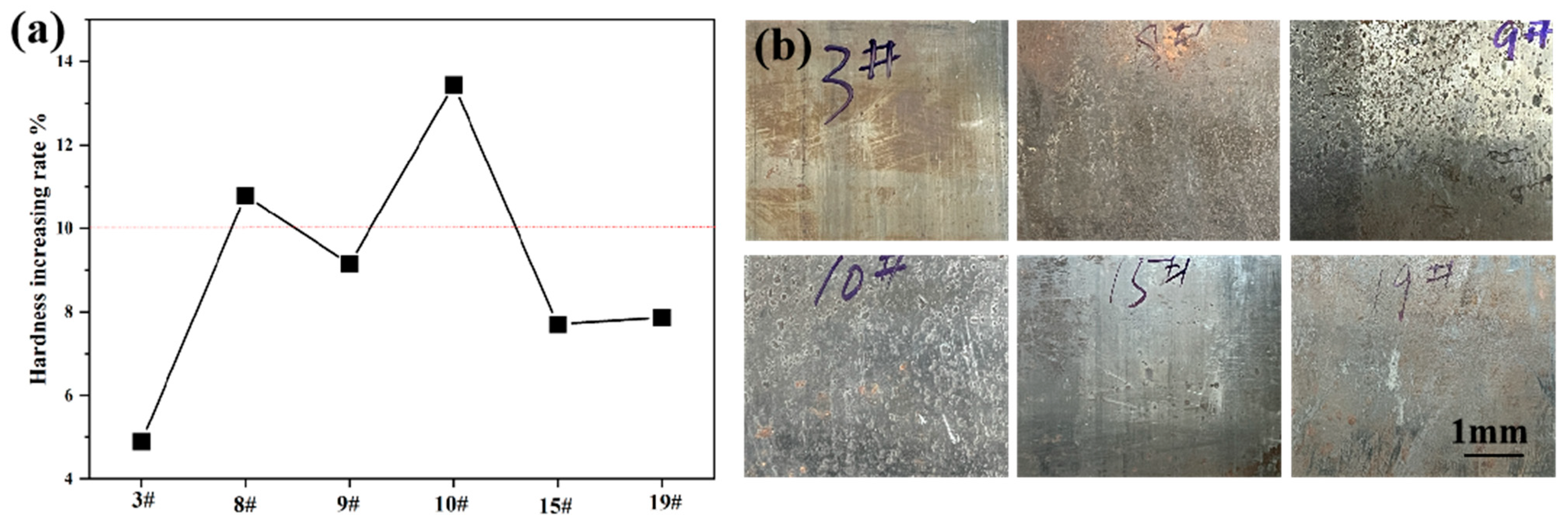
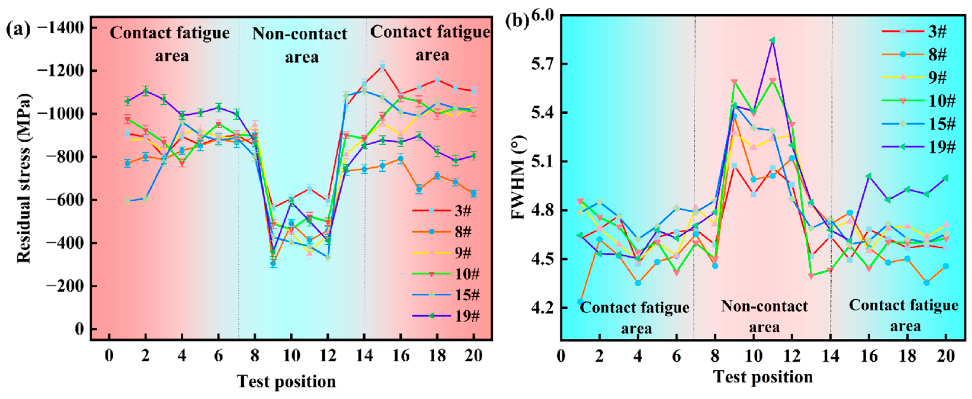
| 3# | 70.4% | 7.45% | 4.89% | weak |
| 8# | 86.2% | 14.15% | 10.79% | strong |
| 9# | 111% | 13.60% | 9.15% | strong |
| 10# | 91.45% | 15.50% | 13.44% | strong |
| 15# | 188.5% | 8.8% | 7.70% | middle |
| 19# | 118% | 11.6% | 7.86% | middle |
Disclaimer/Publisher’s Note: The statements, opinions and data contained in all publications are solely those of the individual author(s) and contributor(s) and not of MDPI and/or the editor(s). MDPI and/or the editor(s) disclaim responsibility for any injury to people or property resulting from any ideas, methods, instructions or products referred to in the content. |
© 2023 by the authors. Licensee MDPI, Basel, Switzerland. This article is an open access article distributed under the terms and conditions of the Creative Commons Attribution (CC BY) license (https://creativecommons.org/licenses/by/4.0/).
Share and Cite
Qu, H.; Yao, L.; Zhan, K. Rolling Contact Fatigue Damage Analysis of G10CrNi3Mo Steel Bearing Inner Ring by X-ray Measurements. Coatings 2023, 13, 2021. https://doi.org/10.3390/coatings13122021
Qu H, Yao L, Zhan K. Rolling Contact Fatigue Damage Analysis of G10CrNi3Mo Steel Bearing Inner Ring by X-ray Measurements. Coatings. 2023; 13(12):2021. https://doi.org/10.3390/coatings13122021
Chicago/Turabian StyleQu, Haixia, Lisong Yao, and Ke Zhan. 2023. "Rolling Contact Fatigue Damage Analysis of G10CrNi3Mo Steel Bearing Inner Ring by X-ray Measurements" Coatings 13, no. 12: 2021. https://doi.org/10.3390/coatings13122021