Article

Tunnel Magnetoresistance-Based Sensor for Biomedical Application: Proof-of-Concept

National Institute of Research and Development for Technical Physics, 700050 Iasi, Romania
*
Authors to whom correspondence should be addressed.
Coatings 2023, 13(2), 227; https://doi.org/10.3390/coatings13020227
Submission received: 21 December 2022 / Revised: 14 January 2023 / Accepted: 16 January 2023 / Published: 18 January 2023
(This article belongs to the Special Issue Ceramic and Metallic Biomaterials. Application in Medical Sciences)

Abstract

:
The aim of this work was to investigate and prove the possibility of the real-time detection of magnetic nanoparticles (MNPs) distributed in solid material by using a tunnel magnetoresistance-based (TMR) sensor. Following the detection tests of FeCrNbB magnetic nanoparticles distributed in transparent epoxy resin (EPON 812) and measuring the sensor output voltage changes at different particle concentrations, the detection ability of the sensor was demonstrated. For the proposed TMR sensor, we measured a maximum magnetoresistance ratio of about 53% and a sensitivity of 1.24%/Oe. This type of sensor could facilitate a new path of research in the field of magnetic hyperthermia by locating cancer cells.

1. Introduction

Features such as cost-effective production, small size, low power consumption, and especially high values of sensitivity and detectivity, recommend magnetoresistive (MR) sensors as the most suitable for biomedical applications [1,2]. Although the most studied magnetoresistive sensors are based on the giant magnetoresistance (GMR) effect, especially due to their high linear response to the applied field as well as the simplification of the technological process, tunnel magnetoresistance (TMR)-based sensors have better sensitivity and resolution due to the higher MR ratio, properties that are very important for biosensor applications [3]. Several methods have been used to improve the linearity and sensitivity of TMR sensors such as optimizing the magnetoresistive structure [4], integrating multiple sensors into the Wheatstone bridge [5], or integrating magnetic flux concentrators (MFCs) [6].
Due to their special magnetic properties and biocompatibility, magnetic nanoparticles can be used in medical applications such as human cell labeling and imaging [7,8] or cancer diagnosis and treatment [9,10]. Currently, the detection of the magnetic responses of MNPs can be performed by magnetorelaxometric imaging (MRX), magnetic resonance imaging (MRI), or magnetic particle imaging (MPI) [8,11,12], but there is a need to improve the cost and efficiency of magnetic nanoparticle localization.
In recent years, different solutions have been proposed for the use of magnetoresistive sensors to detect magnetic particles and evaluate their concentration in ferrofluids [13,14,15] as well as for the indirect detection of biomolecules or bacteria by detecting the magnetic field generated by the magnetic particles adhering to them [16,17,18]. On the other hand, the detection of magnetic nanoparticles by scanning human tissue with a highly sensitive sensor would be of great importance in medicine for use in magnetic hyperthermia, where a major problem is to direct the heat only to the diseased tissue without affecting the surrounding healthy tissue.
In this work, we propose a simple model of a tunnel magnetoresistance (TMR) sensor for the real-time detection of MNPs dispersed in solid material, with potential applications in magnetic hyperthermia by detecting the magnetic particles in tissues. To test the detection performance of the sensor, transparent epoxy resin (EPON 812) was used as a solid material in which the magnetic particles were dispersed. No magnetic flux concentrators or permanent magnets were used to operate the proposed sensor, so no additional steps are required in the fabrication process. The small size of the magnetoresistive device (400 × 250 μm2) allows for the realization of a large number of sensors (100) on a support of 18 × 18 mm2, which means a simplification of the technological process. The fabrication of the magnetoresistive sensing device and its magnetic properties are described in this work as well as the detection limits of the Fe–Cr–Nb–B magnetic nanoparticles dispersed in transparent epoxy resin (EPON 812). The ferromagnetic FeCrNbB nanoparticles (MNPs) prepared by high-energy ball milling from melt-spun ribbons (MSRs) [19] were submicron powders with a glassy structure, whose peculiarity is that the Curie temperature range of 15–50 °C can be changed depending on the Cr content [20]. This makes the magnetic FeCrNbB nanoparticles suitable for biomedical applications, especially hyperthermia applications.

2. Materials and Methods

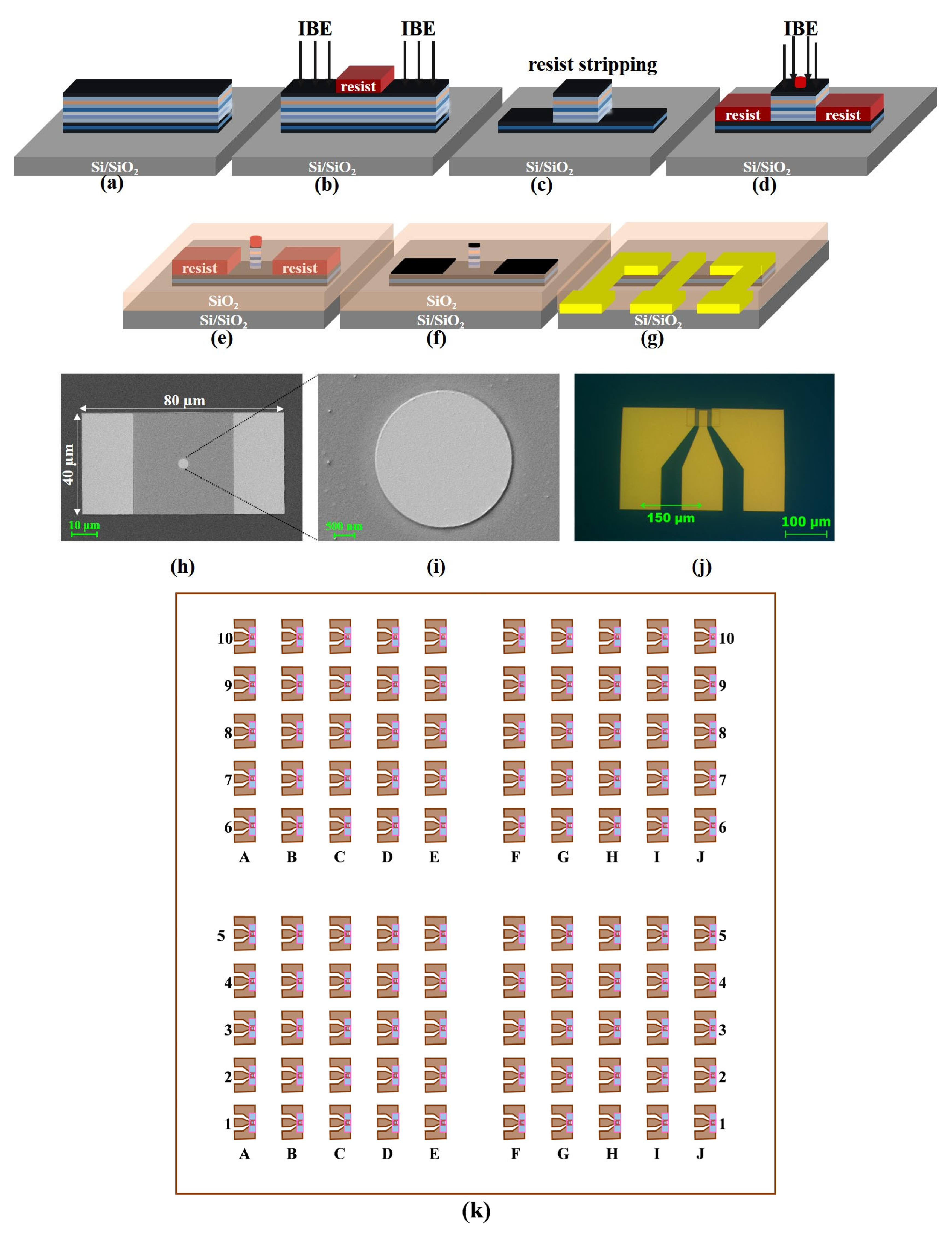
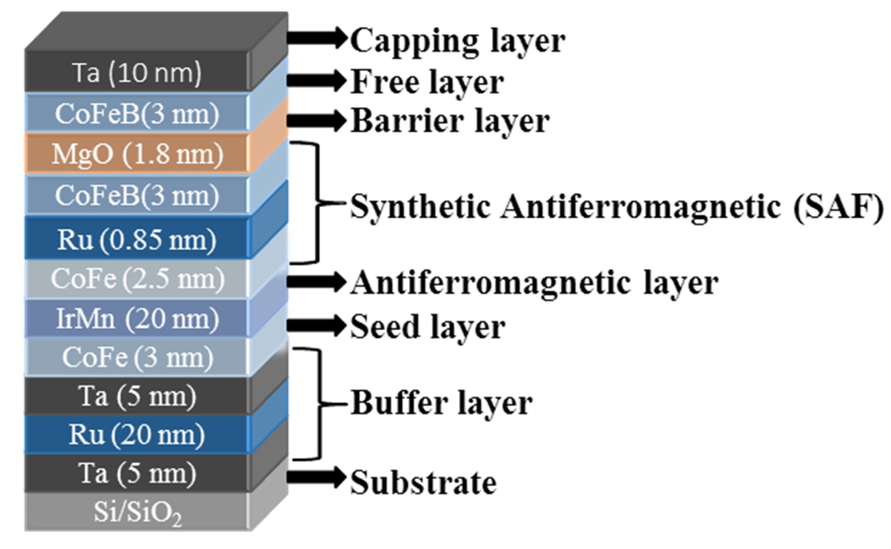
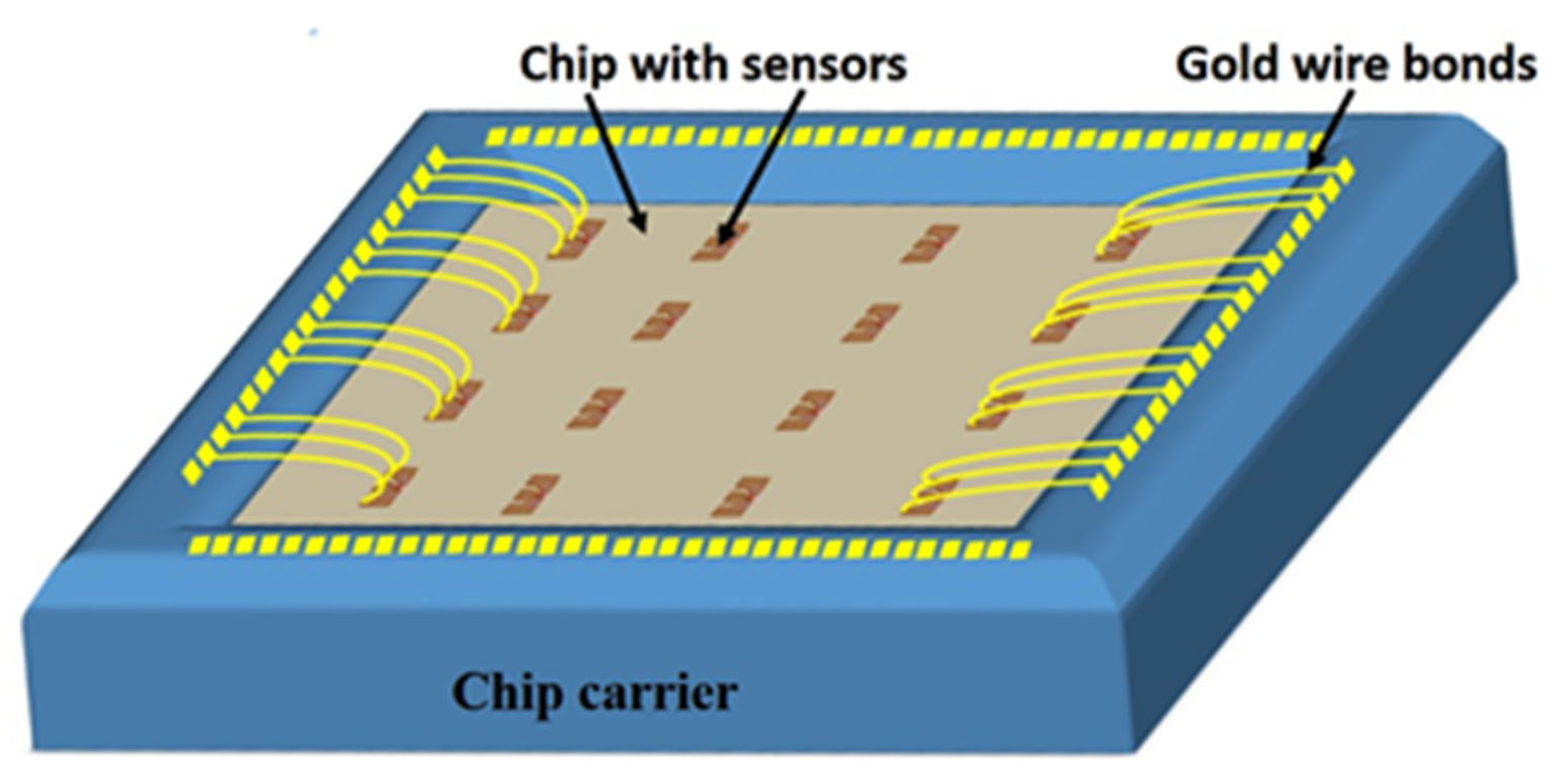
2.1. TMR-Based Sensor Microfabrication

For the structure of the TMR-based sensors studied in this work, a thin layer of magnesium oxide (MgO) was used as the separating layer and Co40Fe40B20 as the free ferromagnetic layer. To achieve higher magnetoresistance values with better sensitivity, the thicknesses of the component layers were optimized, resulting in the final configuration of: Ta (5 nm)/Ru (20 nm)/Ta (5 nm)/CoFe (3 nm)/IrMn (20 nm)/CoFe (2.5 nm)/Ru (0.85 nm)/CoFeB (3 nm)/MgO (1.8 nm)/CoFeB (3 nm)/Ta (10 nm), where the values in parentheses indicate the thickness of each layer, as shown schematically in Figure 1. The thin films were deposited on a Si/SiO2 substrate (18 × 18 mm2) using the ATC 2200/AJA International deposition system (Scituate, MA, USA), which can reach a base pressure of 5 × 10⁻⁸ Torr and allows both magnetron sputter deposition and electron beam evaporation. Except for the MgO barrier layer, which was deposited by electron beam evaporation, all other thin films were prepared by magnetron sputtering at a working pressure of 3 mTorr. During deposition, a magnetic field of 100 Oe was applied parallel to the plane of the thin films to define the easy axis of the ferromagnetic layers.
Magnetoresistive sensors used in MNP detection applications must exhibit a linear change in electrical resistance with the applied magnetic field. It has been shown that in order to achieve this goal, it is advantageous to design the detection elements in rectangular or elliptical shapes (i.e., to have a high aspect ratio). However, as the ratio increases, the sensitivity of the sensor decreases [21]. In this work, we present a detection element structure with a low aspect ratio, with the shape of a cylindrical “pillar” and a diameter of 4 µm. The total size of the device (detection element and contacts) was 400 × 250 μm2, so it is possible to fabricate 100 sensors on a single support. The sensors were divided into four groups of 25 sensors, marked with numbers and letter symbols so that the distinction during the measurements was facilitated (Figure 2k). Being a simple technological process, this type of sensor has the advantage of low cost and short manufacturing time. The microfabrication process of the sensor includes the following steps:
(1) Definition of a TMR structure with a rectangular shape with a size of 40 × 80 μm2 by electron beam lithography (EBL) and ion beam etching (IBE). The detection element and the bottom contact are later defined on this rectangular structure (Figure 2a).
(2) Definition of the bottom contacts by EBL and IBE and resist stripping (Figure 2b,c).
(3) Definition of the detection element by EBL and IBE (Figure 2d). At this stage, the surface of the bottom contacts is protected by e-resist in the same lithography step as that of the pillar.
(4) A 60 nm thick SiO2 insulating layer is deposited on the chip surface by sputtering (Figure 2e). The deposition of the insulating layer is followed by the lift-off process, which exposes only the surfaces covered by the e-resist (Figure 2f). The purpose of the insulating layer is to prevent electrical contact with the bottom contact and the top surface of the MTJ.
(5) Definition of the electrical contacts by laser beam lithography and deposition of Ta (5 nm)/Cu (200 nm). For the measurements, the CPP (current perpendicular to plane) configuration was used, which consists of the electric current flowing perpendicular to the plane of the thin films through the electrical contacts, which have a coplanar waveguide geometry (ground–signal–ground,) Figure 2g).
Figure 2. (ag) Schematic representation of the sensor microfabrication process. (h) SEM image of the magnetoresistive structure of 40 × 80 µm2 and (i) pillar detection element. (j) Optical microscopy image of the final device with coplanar waveguide geometry of the contacts. (k) Schematic representation of a chip with 100 MTJ sensor devices.
Coatings 13 00227 g002

2.2. Magnetic Annealing

Crystallization of the CoFeB layer by magnetic annealing of the MTJ stack with highly (001)-oriented MgO barriers is crucial for maximizing the tunneling magnetoresistance. In magnetic annealing, some properties such as a strongly pinned layer or perpendicular magnetic anisotropy can also be achieved.
The values of temperature, magnetic field, and annealing time can lead to changes in the crystalline structure of the magnesium oxide layer. Therefore, the annealing parameters were studied to choose the appropriate values for each of them.
After we studied the annealing parameters, the magnetic tunnel junction multilayer stack was magnetically annealed for one hour under vacuum conditions at 320 °C and a magnetic field of 5 kOe. During annealing, the magnetic field was applied in the plane of the thin films in the direction of the anisotropy induced during deposition and kept at the same value until the sample reached room temperature. The sample was cooled down naturally to room temperature in about 20 min. Although the conditions for obtaining the magnetoresistive structure are still under investigation and improvements are needed, the images taken with the electron transmission microscope LIBRA®200MC/Carl Zeiss GmbH (Jena, Germany) and shown in Figure 3 demonstrate the transition of the CoFeB/MgO interface from the amorphous state before annealing (Figure 3a) to the crystalline state after annealing (Figure 3b).

2.3. Magnetic Nanoparticles

In order to investigate the detection capability of the sensor, magnetic FeCrNbB nanoparticles (MNPs) with a diameter of 50–500 nm, obtained by high-energy ball milling from melt-spun ribbons (MSRs) precursors [19], were dispersed in transparent epoxy resin (EPON 812) at different concentrations expressed in mass percent. The total mass of epoxy resin and NP mixture was fixed and the mass of NPs was gradually increased to obtain concentrations of 2%, 4%, 6%, and 8%. FeCrNbB particles exhibited high saturation magnetization and soft magnetic properties, which make them a very good candidate for magnetic hyperthermia.
Since epoxy resin has physical and chemical properties similar to human tissue [22], a mold of EPON 812 was prepared for the detection tests in which areas without particles alternated with areas with magnetic particles (Figure 4). Due to its similarity to tissue, epoxy resin is used in a variety of experiments that require the replacement of living organisms [23,24], thus avoiding the ethical problems that the use of human or animal tissue could lead to. Therefore, even in our case, this structure of resin and particles had the task of simulating a human tissue sample in which magnetic particles had been distributed.

3. Results

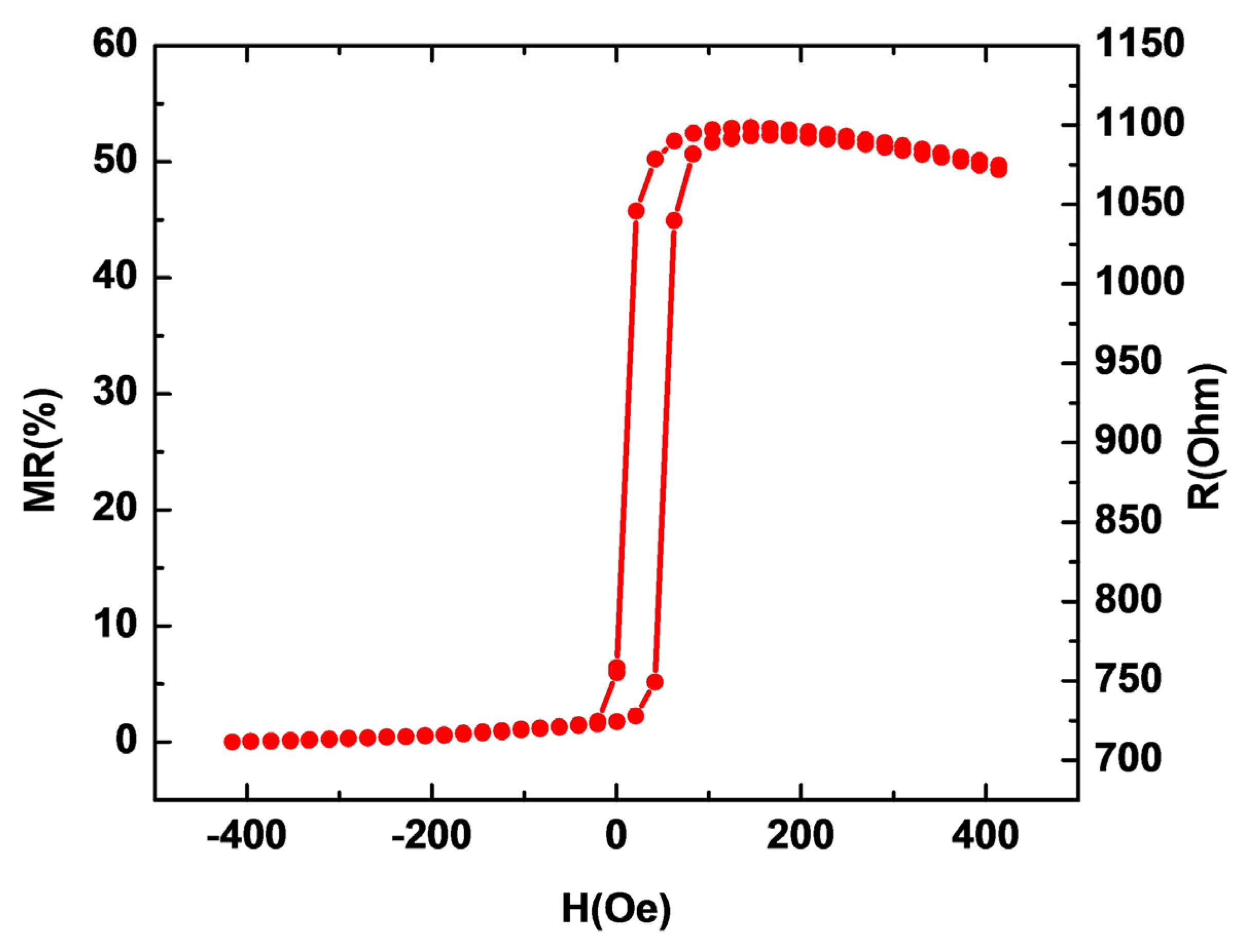
3.1. Sensor Performance

To characterize the performances of the TMR-based sensor, the magnetoresistance curve was drawn by measuring the electrical resistance of the sensor as a function of the applied magnetic field generated by a Helmholtz coil system connected to a bipolar source (Kepko BOP 100–10 MG) and measured with a Gaussmeter equipped with a Hall probe. The magnetic field was applied in the plane of the thin layers of the TMR structure in the direction of the anisotropy induced during deposition. A ground–signal–ground (GSG) probe was used to determine the electrical resistance of the TMR sensor. The system used a DC current source (Keithley 2400, Tektronix, Beaverton, OR, USA) and a multimeter (Keithley 2000, Tektronix, Beaverton, OR, USA) to measure the voltage (Figure 5). Data acquisition and system control were performed using a program developed in LabView.
Measurements of the sensor electrical resistance changes as a function of the applied magnetic field were performed with a bias current of 1 µA flowing through the MTJ sensor. During the measurements, the magnetic field was applied from −400 to +400 Oe in the direction of the easy axis of the pinned layer. From the sensor transfer curve (Figure 6), the proposed TMR sensor had a maximum magnetoresistance ratio of about 53% and a sensitivity of 1.24%/Oe.

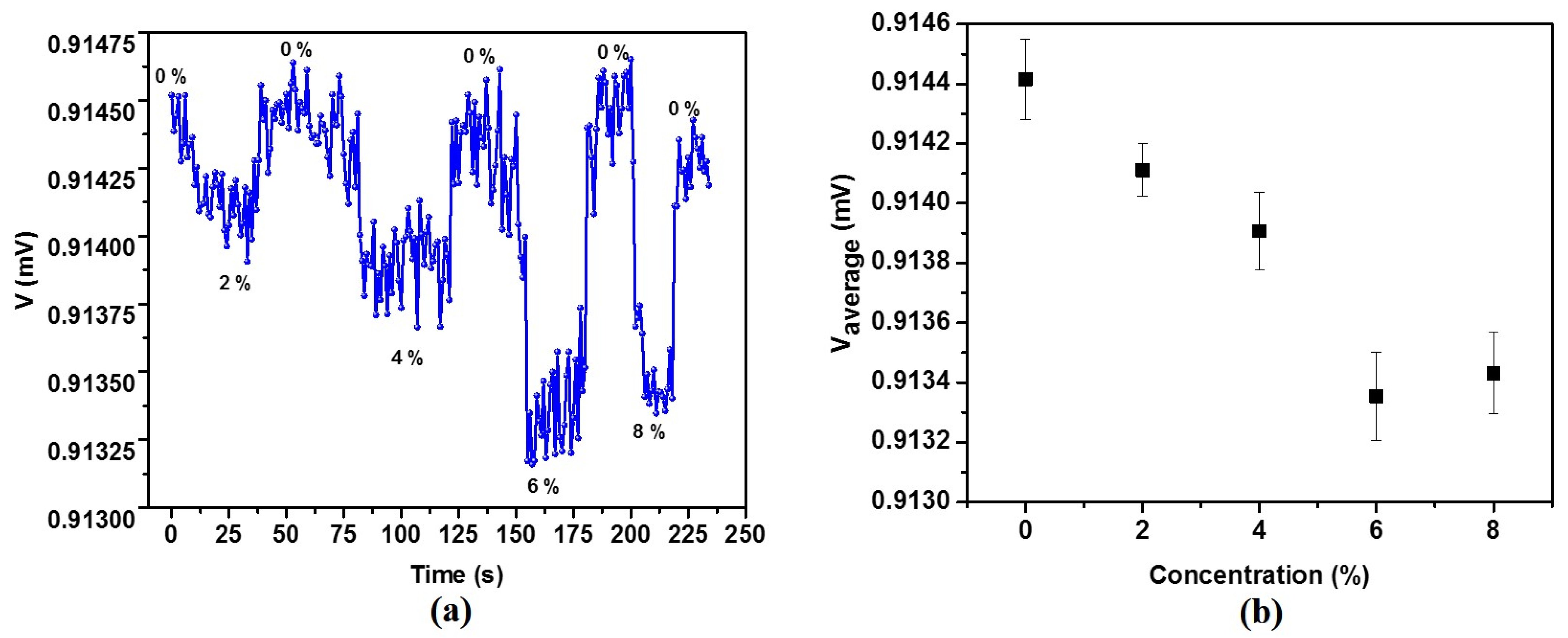
3.2. Detection of Magnetic Nanoparticles

By using the presented sensor prototype, we demonstrated in this work the possibility of detecting different concentrations of magnetic particles distributed in a given volume. Furthermore, the design needs to be improved so that it can be easily used for magnetic sensing, especially for MPN detection. The chip structure containing the sensors will be encapsulated in a chip carrier package that prevents physical damage and corrosion, as shown schematically in Figure 7. A chip wire bonding machine was used to connect the chip to the package.
To magnetize the MNPs in order to obtain a detectable stray magnetic field, an external magnetic field of 20 Oe was applied perpendicular to the film plane of the magnetoresistive sensor. The sensing direction of the sensor coincides with the direction of the easy axis of the pinned layer, therefore, the sensitivity of the sensor is not affected by the applied magnetizing field for the particles.
For the detection measurements, the magnetoresistive sensor was brought to the region of maximum sensitivity of the magnetoresistance curve and then the output voltage of the sensor was measured for a few seconds (Figure 8a) for particle concentrations of 2%, 4%, 6%, and 8%. By calculating the average values of the sensor output voltages measured at the time intervals corresponding to each particle concentration, the graph in Figure 8b was obtained. It can be seen that the sensor voltage decreased linearly with increasing particle concentration from 0% to 6%. The voltage value increased slightly at 8%, which may indicate that the sensor is able to quantify particle concentrations up to a 6% concentration, while it reaches a saturation zone at higher values.

4. Conclusions

We investigated the possibility of detecting magnetic nanoparticles in real-time using a simple TMR-based sensor model. Therefore, we proved the capability of measuring various concentrations of MNPs dispersed in a specific volume by utilizing the sensor prototype that described above. The presented sensor had a relatively high sensitivity and its fabrication did not require additional technological steps as in the case of using different configurations involving permanent magnets (Wheatstone bridge or flux concentrators). It has been shown that the sensor is able to detect in real-time and quantify these concentrations up to a saturation value. We believe that the proposed concept of a simple tunnel magnetoresistance (TMR) sensor for the real-time detection of MNPs could have significant potential applications in localizing cancer cells by detecting the magnetic particles in tissue and in cancer therapy by magnetic hyperthermia.

Author Contributions

Conceptualization, C.G., O.-G.D.-P., M.T., N.L. and H.C.; Methodology, C.G., O.-G.D.-P., M.T. and M.L.; Investigation, C.G., O.-G.D.-P. and M.T.; Writing—original draft preparation, C.G.; Writing—review and editing, C.G, O.-G.D.-P. and M.T; Visualization, N.L. and H.C.; Supervision, C.G.; Project administration, C.G.; Funding acquisition, C.G. All authors have read and agreed to the published version of the manuscript.

Funding

This work was supported by a grant from the Ministry of Research, Innovation, and Digitization, CCCDI—UEFISCDI, project number PN-III-P2-2.1-PED-2021-2739, within PNCDI III.

Institutional Review Board Statement

Not applicable.

Informed Consent Statement

Not applicable.

Data Availability Statement

Not applicable.

Conflicts of Interest

The authors declare no conflict of interest.

References

  1. Lei, Z.Q.; Li, L.; Li, G.J.; Leung, C.W.; Shi, J.; Wong, C.M.; Lo, K.C.; Chan, W.K.; Mak, C.S.K.; Chan, S.B.; et al. Liver cancer immunoassay with magnetic nanoparticles and MgO-based magnetic tunnel junction sensors. J. Appl. Phys. 2012, 111, 07E505. [Google Scholar] [CrossRef] [Green Version]
  2. Sun, X.; Zhi, S.; Lei, C.; Zhou, Y. Investigation of contactless detection using a giant magnetoresistance sensor for detecting prostate specific antigen. Biomed Microdevices 2016, 18, 60. [Google Scholar] [CrossRef] [PubMed]
  3. Nagamine, Y.; Maehara, H.; Tsunekawa, K.; Djayaprawira, D.D.; Watanabe, N.; Yuasa, S.; Ando, K. Ultralow resistance-area product of 0.4 Ω(Μm)2 and high magnetoresistance above 50% in CoFeB/MgO/CoFeB magnetic tunnel junctions. Appl. Phys. Lett. 2006, 89, 162507. [Google Scholar] [CrossRef]
  4. Cardoso, S.; Leitao, D.C.; Gameiro, L.; Cardoso, F.; Ferreira, R.; Paz, E.; Freitas, P.P. Magnetic tunnel junction sensors with pTesla sensitivity. Microsyst. Technol. 2014, 20, 793–802. [Google Scholar] [CrossRef]
  5. Zhang, Y.; He, G.; Zhang, X.; Xiao, G. Magnetotransport and electronic noise in superparamagnetic magnetic tunnel junctions. Appl. Phys. Lett. 2019, 115, 022402. [Google Scholar] [CrossRef]
  6. Franco, F.; Cardoso, S.; Freitas, P.P. Reconfigurable spintronics wheatstone bridge sensors with offset voltage compensation at wafer level. IEEE Trans. Magn. 2019, 55, 4400705. [Google Scholar] [CrossRef]
  7. Reddy, L.H.; Arias, J.L.; Nicolas, J.; Couvreur, P. Magnetic nanoparticles: Design and characterization, toxicity and biocompatibility, pharmaceutical and biomedical applications. Chem. Rev. 2012, 112, 5818–5878. [Google Scholar] [CrossRef]
  8. Weissleder, R.; Cheng, H.C.; Bogdanova, A.; Bogdanov, A., Jr. Magnetically labeled cells can be detected by MR imaging. J. Magn. Reson. Imaging 1997, 7, 258–263. [Google Scholar] [CrossRef]
  9. Ahmed, M.; Douek, M. The role of magnetic nanoparticles in the localization and treatment of breast cancer. Biomed Res. Int. 2013, 281230. [Google Scholar] [CrossRef]
  10. Revia, R.A.; Zhang, M. Magnetite nanoparticles for cancer diagnosis, treatment, and treatment monitoring: Recent advances. Mater. Today 2016, 19, 157–168. [Google Scholar] [CrossRef]
  11. Liebl, M.; Steinhoff, U.; Wiekhorst, F.; Haueisen, J.; Trahms, L. Quantitative imaging of magnetic nanoparticles by magnetorelaxometry with multiple excitation coil. Phys. Med. Biol. 2014, 59, 6607–6620. [Google Scholar] [CrossRef]
  12. Gleich, B.; Weizenecker, J. Tomographic imaging using the nonlinear response of magnetic particles. Nature 2005, 435, 1214–1217. [Google Scholar] [CrossRef]
  13. Mukhopadhyay, S.C.; Chomsuwan, K.; Gooneratne, C.P.; Yamada, S. A novel needle-type SV-GMR sensor for biomedical applications. IEEE Sens. J. 2007, 7, 401–408. [Google Scholar] [CrossRef]
  14. Loureiro, J.; Fermon, C.; Pannetier-Lecoeur, M.; Arrias, G.; Ferreira, R.; Cardoso, S.; Freitas, P.P. Magnetoresistive detection of magnetic beads flowing at high speed in microfluidic channels. IEEE Trans. Magn. 2009, 45, 4873–4876. [Google Scholar] [CrossRef]
  15. Li, L.; Mak, K.Y.; Leung, C.W.; Ng, S.M.; Lei, Z.Q.; Pong, P.W.T. Detection of 10-nm superparamagnetic iron oxide nanoparticles using exchange-biased GMR sensors in wheatstone bridge. IEEE Trans. Magn. 2013, 49, 4056–4059. [Google Scholar] [CrossRef] [Green Version]
  16. Kokkinis, G.; Jamalieh, M.; Cardoso, F.; Cardoso, S.; Keplinger, F.; Giouroudi, I. Magnetic-based biomolecule detection using giant magnetoresistance sensors. J. Appl. Phys. 2015, 117, 17B731. [Google Scholar] [CrossRef]
  17. Yang, S.-Y.; Lien, K.-Y.; Huang, K.-J.; Lei, H.-Y.; Lee, G.-B. Micro flow cytometry utilizing a magnetic bead-based immunoassay for rapid virus detection. Biosens. Bioelectron. 2008, 24, 855–862. [Google Scholar] [CrossRef]
  18. Herea, D.-D.; Labusca, L.; Radu, E.; Chiriac, H.; Grigoras, M.; Panzaru, O.D.; Lupu, N. Human adipose-derived stem cells loaded with drug-coated magnetic nanoparticles for in-vitro tumor cells targeting. Mater. Sci. Eng. C 2019, 94, 666–676. [Google Scholar] [CrossRef]
  19. Chiriac, H.; Lupu, N.; Lostun, M.; Ababei, G.; Grigoraş, M.; Dănceanu, C. Low TC Fe-Cr-Nb-B glassy submicron powders for hyperthermia applications. J. Appl. Phys. 2014, 115, 17B520. [Google Scholar] [CrossRef]
  20. Chiriac, H.; Whitmore, L.; Grigoras, M.; Ababei, G.; Stoian, G.; Lupu, N. Influence of Cr on the nanoclusters formation and superferromagnetic behavior of Fe-Cr-Nb-B glassy alloys. J. Appl. Phys. 2015, 117, 17B522. [Google Scholar] [CrossRef]
  21. Luz Ventosa, T.L.L. High Performance Magnetic Tunnel Junctions for Magnetic Scanning. Master’s Thesis, Instituto Superi-or Tecnico, Lisboa, Portugal, May 2017. [Google Scholar]
  22. Edris, A.; Choi, B.; Aguilar, G.; Nelson, J.S. Measurements of laser light attenuation following cryogen spray cooling spurt termination. Laser Surg. Med. 2003, 32, 143–147. [Google Scholar] [CrossRef] [PubMed] [Green Version]
  23. White, D.R.; Martin, R.J.; Darlison, R. Epoxy resin based tissue substitutes. Br. J. Radiol. 1977, 50, 814–821. [Google Scholar] [CrossRef] [PubMed]
  24. Yemby, H.T.; Arnold, M.P.; Giancarlo, A.V.; Felipe, C.; José, V.R. Construction and characterization of materials equivalent to the tissues and organs of the human body for radiotherapy. Radiat. Phys. Chem. 2019, 159, 70–75. [Google Scholar] [CrossRef]
Figure 1. Schematic representation of the TMR multilayer structure.
Coatings 13 00227 g001
Figure 3. (a) TEM image of the CoFeB/MgO interface before annealing; (b) TEM image of the CoFeB/MgO interface after annealing.
Coatings 13 00227 g003
Figure 4. (a) Schematic representation of the resin/resin + magnetic particle assembly with different concentrations and of the magnetoresistive device; (b) Optical image of the sensor and the resin/resin + particle assembly, before being placed in the detection area.
Coatings 13 00227 g004
Figure 5. Schematic diagram and image of the experimental setup used for the TMR measurements.
Coatings 13 00227 g005
Figure 6. Sensor transfer curve.
Coatings 13 00227 g006
Figure 7. Schematic of the housing in which the chip structure is bonded to the chip carrier.
Coatings 13 00227 g007
Figure 8. (a) Variation in the sensor output voltage in time for different particle concentrations; (b) the average value of the output voltages as a function of particle concentration.
Coatings 13 00227 g008
Disclaimer/Publisher’s Note: The statements, opinions and data contained in all publications are solely those of the individual author(s) and contributor(s) and not of MDPI and/or the editor(s). MDPI and/or the editor(s) disclaim responsibility for any injury to people or property resulting from any ideas, methods, instructions or products referred to in the content.

