Article

Microstructure and Mechanical Properties of Co-Deposited Ti-Ni Films Prepared by Magnetron Sputtering

1
Avic Chengfei Commercial Aircraft Co., Ltd., Chengdu 610092, China
2
Tianjin Key Laboratory of Materials Laminating Fabrication and Interface Control Technology, School of Material Science and Engineering, Hebei University of Technology, Tianjin 300130, China
*
Author to whom correspondence should be addressed.
Coatings 2023, 13(3), 524; https://doi.org/10.3390/coatings13030524
Submission received: 9 February 2023 / Revised: 23 February 2023 / Accepted: 24 February 2023 / Published: 27 February 2023
(This article belongs to the Special Issue Novel Coatings for Corrosion Protection)

Abstract

:
Ti-Ni films with various Ni contents (16.5, 22.0, 33.5 at. %) were deposited on Al alloy substrates using DC magnetron co-sputtering. The effects of Ni target power and substrate bias (−10, −70, −110 V) on morphologies, crystallography, nanomechanical properties and scratch behavior of films were studied. All the deposited Ti-Ni films exhibited a BCC structure of β-Ti (Ni). The Ti-Ni films grew with a normal columnar structure with good bonding to substrates. When increasing the Ni target power and substrate bias, the grain size grew larger and the surface became denser. The as-deposited Ti-Ni films significantly improved the hardness (>4 GPa) of the Al alloy substrate. With the increase of bias voltage, the hardness and modulus of the film increased. The hardness and modulus of the Ti-22.0Ni film prepared at −70 V bias were 5.17 GPa and 97.6 GPa, respectively, and it had good adhesion to the substrate.

1. Introduction

Titanium and its alloys have excellent properties including low density, high specific strength, and strong corrosion resistance, and are widely used in aerospace, automobile, biomedical applications and other fields [1,2,3,4,5,6]. Moreover, Ti-based metal films prepared using magnetron sputtering have also attracted interest. Several works have reported the microstructure of pure Ti film (α-Ti, hcp), which is related to the sputtering parameters including target power, bias and deposition temperature [7,8,9,10,11,12]. In recent years, β-Ti alloys (bcc) have gained increasing attention due to their excellent strength and rigid combinations. Notably, the lower elastic modulus of β-Ti makes it more compatible with bone, showing great prospects in biomedical fields [13,14,15]. Microstructural features such as morphology, grain size, density and texture strongly affect structural and functional properties of Ti films [16,17,18]. Thus, it is important to understand the microstructure and performance of β-Ti films for potential applications.
It is known that a solid solution is vital to strengthen the mechanical properties of Ti alloys. The addition of β-stabilizing elements (e.g., Mo, V, Nb, Ni, Cr, Fe, Ta) could shift the β-transition into lower temperatures. The content of alloying elements greatly affects the phase composition and mechanical properties. Both β and α + β alloys exhibit excellent biocompatibility and are widely used in medical applications [19]. The addition of β-stabilizing elements such as Zr and Mo to titanium alloys improves their mechanical properties and biocompatibility, resulting in a good combination of ductility, strength, and strain hardening rate. As for casted Ti-Cr and Ti-Mo alloys, only 10 wt% Cr or Mo addition is required to form the β phase [20,21]. In the spark plasma sintered Ti-Mo alloy, the highest hardness (592 HV0.3), highest flexural strength (∼2 GPa) and maximum ultimate tensile strength (852 MPa) are achieved for Ti-16Mo, Ti-12Mo and Ti-8Mo alloys (wt.%), respectively [22]. According to Lee et. al., the hcp phase (α) is dominated in Ti-Nb alloys with 15 wt.% or less Nb, while the bcc phase (β) is retained with more than 27.5 wt.% Nb [23]. In view of the powerful β-stabilizing ability of Mo elements, the equivalent percentage of Mo could be established with other betagenic elements [24]. Studies have shown that adding Ni to Ti-based alloys can enhance the stability of the β phase, thereby improving the overall mechanical properties of the material. The addition of Ni can also adjust the phase transition temperature of Ti-Ni alloys, which is crucial for shape memory applications. However, there still exist many unclear issues between β-stabilizing elements and microstructure features of Ti alloys.
In the mass production of β-Ti alloys, a rapid cooling process is often necessary after a high-temperature heating treatment or rapid sintering, as stated in Reference [25]. Nevertheless, magnetron sputtering of Ti-Me films can be easily achieved with a large series of composition just by regulating the power of co-deposited Ti and Me targets. This would be convincing for optimizing the chemical composition of bulk Ti alloys. Photiou et al. [26] revealed the structure–property relationships for magnetron-sputtered Ti-Nb films covering a broad Nb range. The β-Ti phase can be stabilized with Nb content beyond 20 at%. The Ti-15at%Nb film exhibited the lowest elastic modulus of ~85 GPa. In our previous study of Ti-Cr film (Cr, 0~40 at. %) [27], only 10% Cr could stabilize the β phase. Note that the increasing Cr content has little change in the modulus of Ti-Cr films, retaining the values at ~95 GPa. Liu et al. [28] revealed the phase formation and morphology evolution of sputtered Ti-Mo films under different substrate temperatures. The Ti-15Mo film could retain the β phase at 50~100 ℃, while the Ti-30Mo film could maintain the β phase at higher temperatures up to 300 ℃. Researchers have also explored other Ti alloy films, such as Ti-Al, Ti-Ag and Ti-Cu films, for potential biomedical applications [29,30,31,32].
The shape memory effects of Ti-Ni-based alloys or films have been the focus of many studies [33,34,35,36,37], but the structure–property relationship of Ti-Ni alloys in the Ti-rich region (<40 at%) has been rarely reported. In view of the complex processes and cost of cast Ti-Ni bulks, this study employed magnetron sputtering to deposit Ti-Ni films with a series of Ni content by adjusting the Ni target power. The effect of deposition parameters on the phase composition and mechanical properties were also investigated. Through the thin film technique, the Ni composition–structure–property relationships in Ti-Ni alloys are conveniently revealed. This might provide useful guides to tailor compositions in bulk Ti-Ni alloys. The β-phase of Ti-Ni-based alloys is an important research area, and studying the formation mechanism and phase transformation behavior of the β-phase is crucial for understanding β-Ti(Ni) alloys. Considering the need for good bonding between Ti-Ni films and substrate, metallic Al instead of glass or silicon pieces is used as a substrate. The good mutual solubility and property matching between the Ti-Ni film and Al produce good adhesion without flaking. Meanwhile, Ti-Ni films can enhance the surface hardness and corrosion resistance of the relatively soft Al substrate. In addition, post-annealing could stimulate the surface alloying of Ti and Ni on the Al substrate, thus enhancing its surface properties and prolonging the service life of the aluminum alloy.

2. Materials and Methods

Commercial 2024-Al alloy disks (Φ 20 mm × 4 mm) were used as substrate. The substrate was ground with sandpaper and polished into a mirror-like surface, then ultrasonically cleaned with acetone solution for about 30 min.
Using a magnetron sputtering technique with pure Ti and pure Ni targets (Omat Advanced Materials Co., Ltd., Dongguan, China), Ti-Ni alloy films were created on substrates. The parameters are shown in Table 1. Firstly, the bias voltage of the workpiece was first fixed at −70 V. Meanwhile, the Ti target power was fixed at 1.5 kW as basic composition and we changed the Ni target power to 0.1 kW, 0.15 kW and 0.25 kW to obtain different Ni contents. The corresponding Ti-Ni films were denoted as DTN-1, DTN-2 and DTN-3. Consequently, the Ti target power and Ni target power were fixed and we changed the substrate bias at −10 V and −110 V. The corresponding samples were recorded as DTN-4 and DTN-5.
The phase structure of the films was detected using an X-ray diffractometer (XRD) (Rigaku D/max 2500, Tokyo, Japan) with a Cu Kα source (λ = 1.542 Å), The parameters were shown as scanning angle range of 2θ = 10°–90°, and scanning speed of 4° min−1. The morphologies of the films were characterized by scanning electron microscope (JSM7100F, JEOL, Tokyo, Japan) equipped with an energy dispersive spectrometer (EDS). The particle size of the film was measured by Nano Measure software using surface SEM images. The element distribution was determined by JXA-8530 electron probe micro analyzer (EPMA, JEOL, Tokyo, Japan).
A dynamic ultra-micro hardness tester (DUH-211S, SHIMADZU, Kyoto, Japan) was used to evaluate the mechanical properties of Ti-Ni films. The test force was 30 mN, the loading speed was 1 mN/s and dwell time was 10 s. The hardness and Young’s modulus were obtained by the obtained load-displacement curves. The scratch test (WS-2005, Lanzhou institute of chemical physics, Lanzhou, China) of the films was carried out using a diamond tip, and the fracture resistance and adhesion strength data of the film were obtained. The maximum load was 80 N, the loading rate was 80 N/min and scratch distance was 2 mm.

3. Results and Discussions

3.1. Phase Analysis of Ti-Ni Films

Figure 1 shows the XRD patterns of the Ti-Ni films deposited at different Ni target powers and different bias pressures. It is apparent that all the Ti-Ni films were crystallized in a β-Ti(Ni) structure with a preferred orientation along the (110) plane. The broad peaks of (110) suggest the presence of nanocrystals in the Ti-Ni films. The XRD peak width between 34~46° becomes broader with the increase of Ni target power, implying the grain refinement in Ti-Ni films. However, the increasing substrate bias results in a slight shrinking of the (110) peak, indicating improved crystallinity. The higher target power generates more Ni atoms with higher energy, facilitating the nucleation of Ti-Ni films. In addition, the higher bias provides more kinetic energy of atoms to bombard the substrate, thus accelerating the surface diffusion of atoms and grain growth. Typically, the β-Ti phase forms at high temperatures. However, during magnetron sputtering, the high kinetic energy of particles dissipates rapidly, creating extremely rapid cooling and freezing conditions for the formation of the β phase. Moreover, the co-sputtering with Ni elements stabilizes the β phase in Ti-Ni films. It is also consistent with the finding that the addition of alloying elements (e.g., Cr, Nb, Mo, etc.) promotes the stabilization of the β-phase in the Ti-based alloy films [26,27,28]. According to a previous study of Ti-Cr films, with the addition of ~10 at. % Cr, the hcp pure Ti (α-Ti) is converted to a bcc structure (β-Ti) for the Ti-Cr alloy film [27]. In the study of Ti-Nb films, D. Photiou et al. [26] also found that when the Nb content is 20% or more, the stable β phase structure is promoted.

3.2. Surface Morphology and Chemical Composition of Ti-Ni Films

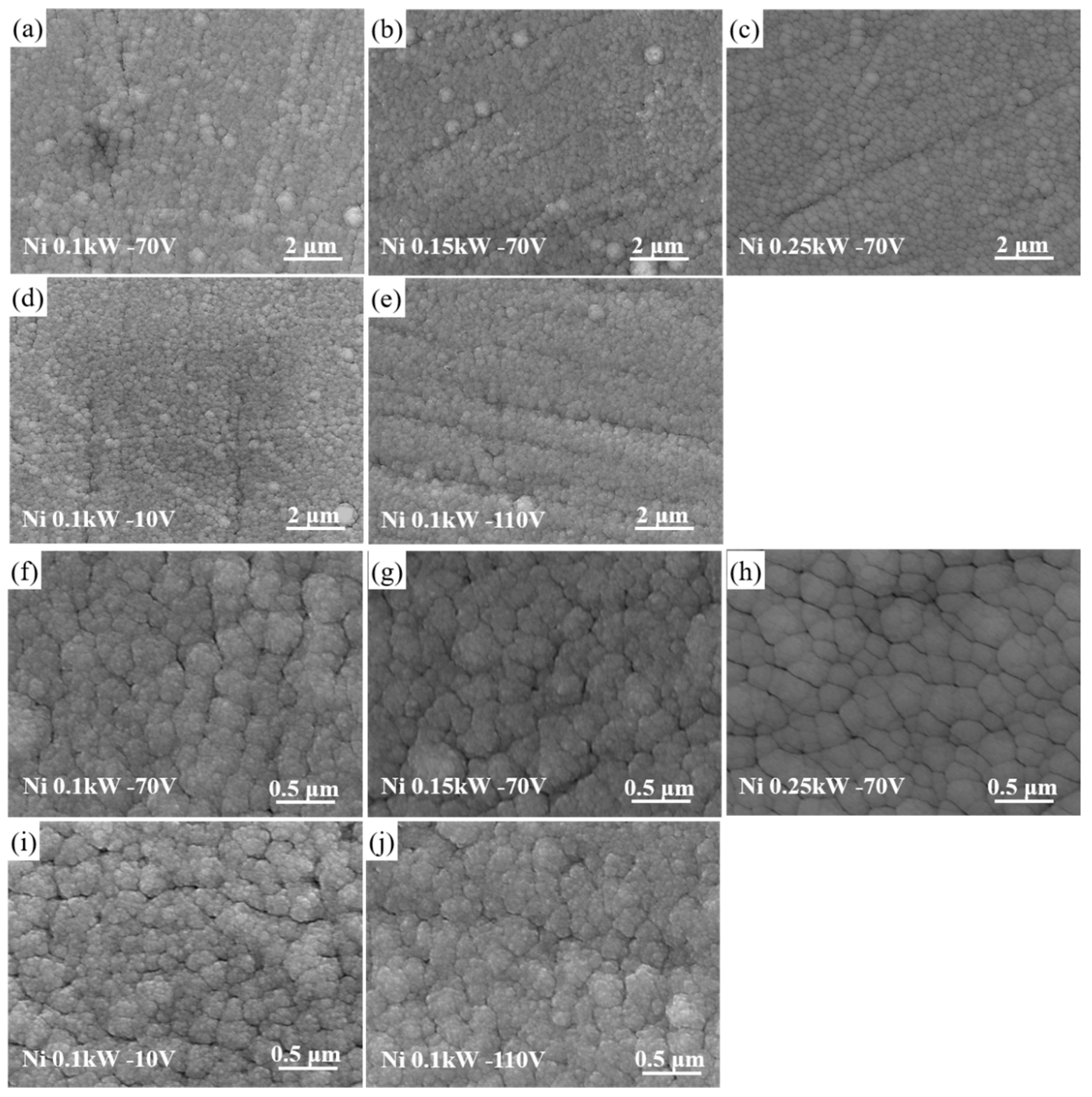
Figure 2 displays the surface morphologies of Ti-Ni films deposited at different Ni target power and substrate bias. The corresponding compositions are summarized in Table 2. The average Ni content of DTN-1, DTN-2 and DTN-3 films were 16.5%, 22.0% and 33.5% (at. %), respectively. Thus, we can refer to the three samples as Ti-16.5Ni, Ti-22Ni, and Ti-33.5Ni films. It should be noted that the substrate bias did not significantly alter the chemical composition of the Ti-16.5Ni film.
As seen from Figure 2a–e, all the β-Ti(Ni) films show spherical aggregate morphology with some abnormal large grains. The high magnified images (Figure 2f–j) show that the spherical domains are constituted of nanoscale particles (20~50 nm). However, voids are also visible between adjacent domains. The continuous bombardment of energic particles on the previous films generates more nucleation sites, thus forming fine grains in the domains. As described in Figure 3, the average size of the spherical domains is 269, 311, 327, 231 and 326 nm for DTN-1, DTN-2, DTN-3, DTN-4 and DTN-5 films, respectively. Interestingly, with increasing Ni target power, the size of the spherical particles increases. The surface of domain (Figure 2h) becomes much smoother. However, in the study of D. Photiou et al. [26], the increase in Nb target power resulted in smaller particle size of the films. Higher target power generates more energic atoms, and thus might result in a sputtering-depositing effect on the as-deposited surface. Meanwhile, the surface migration of Ti, Ni atoms is enhanced. These two factors are ascribed to the smooth feature of the Ti-33.5Ni film. As seen from Figure 2f–j, the substrate bias has a slight effect on the growth feature of the Ti-16.5Ni film. However, the film becomes denser and the internal particles grow larger with the increasing bias. As reported in [27], the α-Ti film grows cauliflower-like features with a loose structure, while the β-Ti(Cr) films grow with globular particles. The Nb addition also leads to the formation of a β phase with round particles in Ti-Nb films (20~44 at. %) [26]. These indicate that β-stabilizing elements (Cr, Nb and Ni) generate a similar sphere domain growth in β-Ti films.
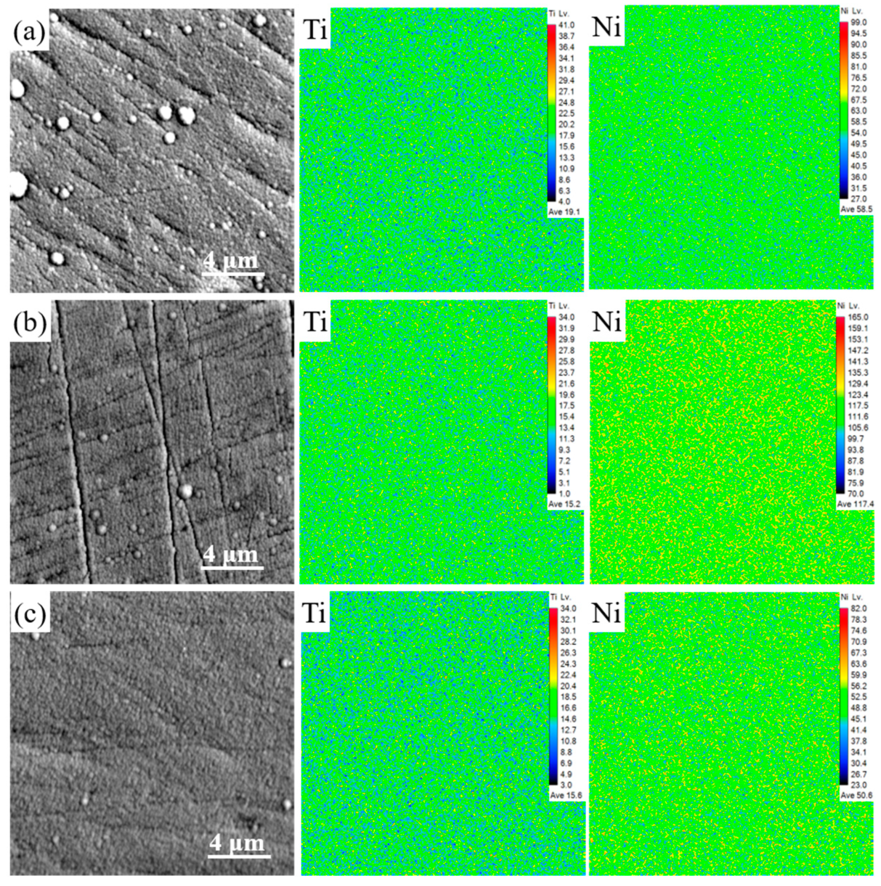
The elemental distribution of the films was analyzed using EPMA. Figure 4 shows the surface elemental distribution of DTN-1, DTN-3 and DTN-5 films. The Ti and Ni elements are uniformly dispersed without segregation. As the Ni target power increases, the Ni content on the surface of DTN-3 rises more than that on the surface of DTN-1, which is consistent with the results in Table 2. In addition, the Ti and Ni maps hardly change with the increase of substrate bias from −70 V to −110 V. These results imply that co-sputtering is a favorable method to produce homogeneous alloys and as such could provide guidelines for bulk alloy design.

3.3. Cross-Sectional and Fracture Morphology of Ti-Ni Films

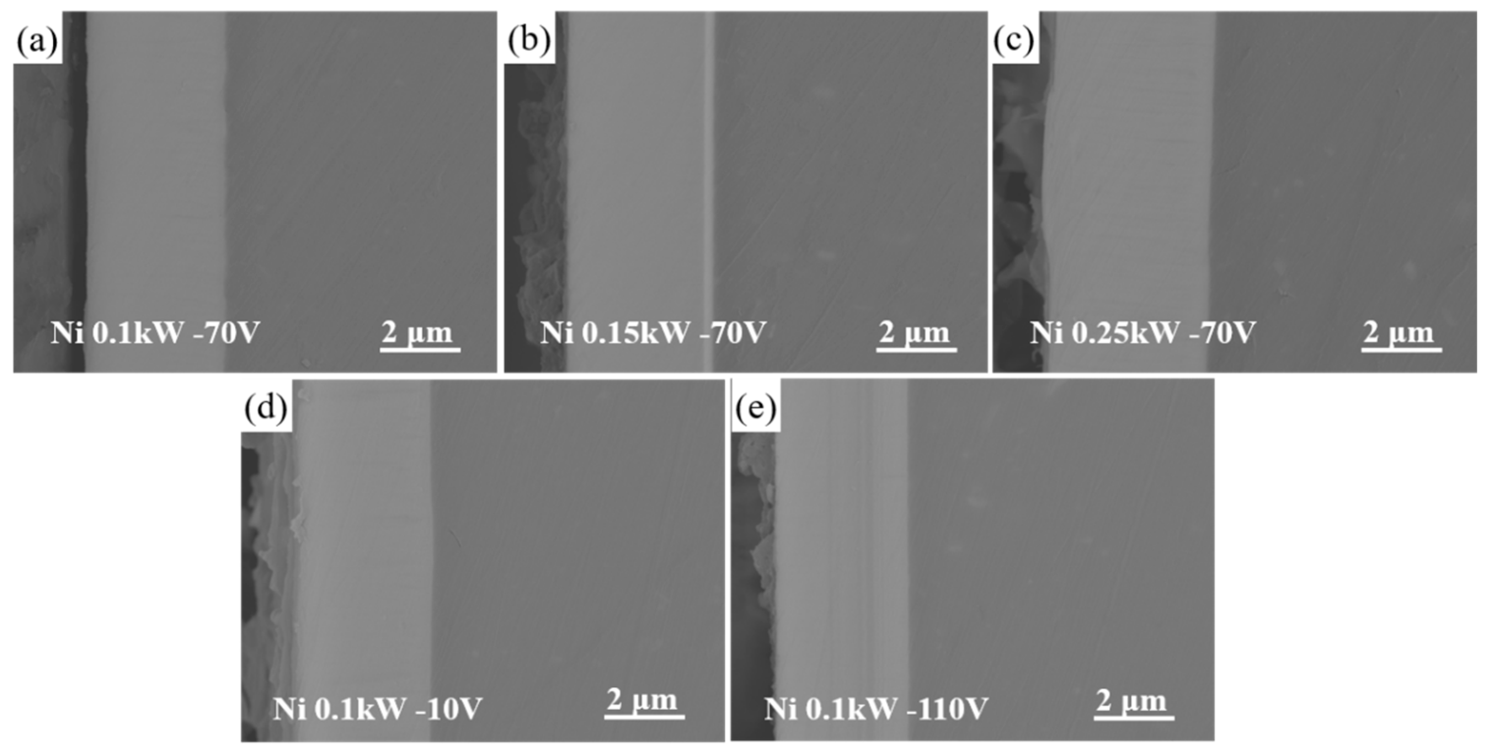
Figure 5 displays the cross-sectional morphology of the Ti-Ni films. It is clear that there are no voids or cracks at the interface between the Ti-Ni films and the Al substrates, implying good bonding state. The thickness of the Ti-16.5Ni, Ti-22Ni and Ti-33.5Ni films is 3.46, 3.82, and 4.09 μm, respectively. Obviously, the increasing Ni target power leads to thicker films. As seen from Figure 5a,d,e, the thickness of the Ti-16.5Ni film at the bias of −10 V, −70 V and −110 V is 3.47, 3.46 and 3.36 μm, respectively. The decrease in film thickness at high bias pressure was attributed to the back-sputtering effect of Ar ions. The thickness of Ti-Ni films increased with increasing Ni target power at the same Ti target power. Under the same Ni target power condition, the bias has little effect on the film thickness. The results demonstrate that the thickness of Ti-Ni films can be controlled by varying the Ni target power during co-sputtering. These results provide valuable guidance for the design of bulk alloys and demonstrate the potential of co-sputtering for producing homogeneous alloys with controlled thickness.
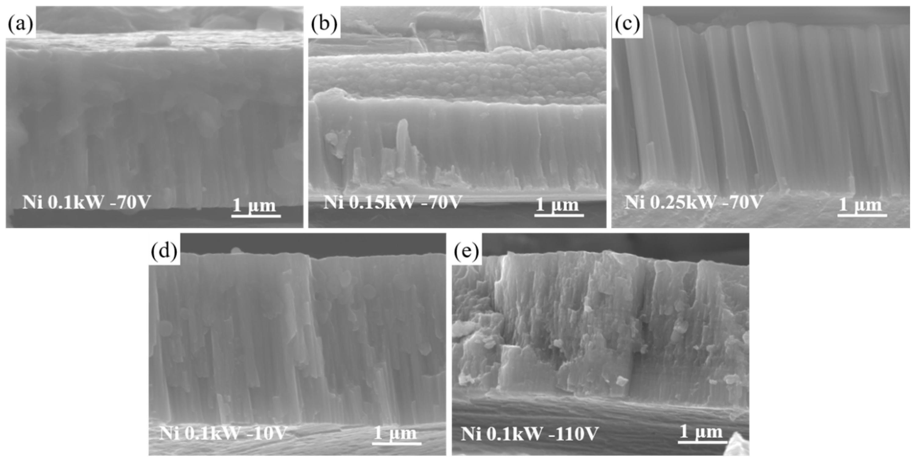
From the fracture morphology in Figure 6, all the Ti-Ni films exhibit a typical columnar structure, which is a typical morphology of the ion sputter-deposited film [7,11]. As the film thickness increases, the columnar clusters become refined at the bottom. Notably, the columnar clusters in the Ti-33.5Ni film show fiber-like characteristics. At lower substrate bias, the columnar structure is coarse and there are large gaps. With the increasing bias, the columnar morphology is not apparent, the gaps decrease, and the film becomes denser. This can be attributed to the fact that an increase in bias results in an increase in the kinetic energy of atoms, thereby enhancing their migration ability in the plane direction, which in turn inhibits the perpendicular growth of columnar crystals.

3.4. Nano-Indentation Test of Ti-Ni Films

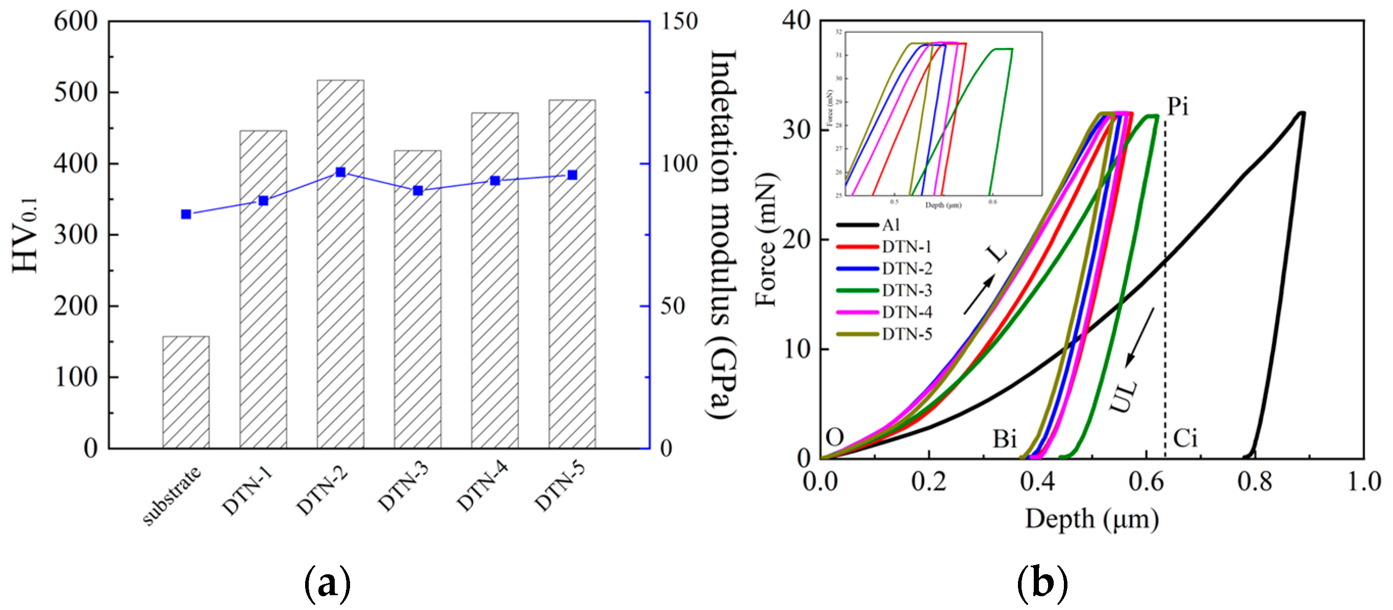
Figure 7 shows the nanoindentation hardness and elastic modulus of Ti-Ni films and the load-displacement curves. The elastic-plastic deformation ability of films is calculated according to the curves, and the corresponding values are summarized in Table 3. The hardness of the Ti-16.5Ni, Ti-22Ni and Ti-33.5Ni films is 4.45, 5.17 and 4.18 GPa. The corresponding modulus is 87, 97.6 and 90.5 Gpa, respectively. As seen from the XRD results in Figure 1, the relatively sharp peak of the (110) plane indicates the better crystallinity of the Ti-22Ni film, which explains its high hardness. The hardness of the Ti-16.5Ni film at −10 V and −110V is 4.71 and 4.89 GPa, and the elastic modulus is 94.5 and 96 GPa, respectively. With the increasing bias, the DTN-5 film also has a sharper (110) peak and denser surface, thus leading to the improved hardness. The modulus of the present Ti-Ni films (87~86 GPa) is close to that of our previous β-Ti(Cr) films (~95 GPa). It has been reported [38] that the hardness of Ti-Ni alloys prepared by selective laser melting (SLM) fluctuates around 255 ± 10 HV0.2. The Ti-Ni films deposited in this study show significantly improved hardness compared to that of SLM-TiNi alloys. In addition, the hardness and modulus of the Ti-Ni films are significantly higher than that of the 2024 Al alloy substrate (1.57 and 82 GPa).
In conditions of elastic-plastic behavior, the ability of a material to withstand elastic strain before failure can be described by the ratio of hardness (H) to Young’s modulus (E), and materials with a higher H/E usually exhibit lower wear rates; resistance to plastic deformation to failure can be described by H3/E2, and materials with high hardness and low modulus have a lower tendency towards plastic deformation [39]. As shown in Table 3, the Ti-22Ni film has the maximum H/E value. However, the H/E value decreases at higher Ni content. As for the Ti-16.5Ni film, the substrate bias has little change in the H/E value. The trend of the effect of different deposition conditions on H3/E2 is similar to that of H/E.
Figure 7b displays the load-displacement curves of Ti-Ni alloy films; the total deformation work Wt is defined by the area under the loading curve (AOPiCi) and the plastic deformation work Wp is defined by the area of the closed area of the loading and unloading curves (AOPiBi), both of which are used to assess the elastic and plastic deformation behavior of the material, respectively. The plasticity factor (ηp = Wp/Wt) is used to assess the material’s resistance to plastic deformation, and a larger value indicates a stronger plastic deformation ability of the material. As can be seen from Table 3, the ηp value of the 2024 aluminum alloy is 0.87, indicating its strong plastic deformation ability; the ηp values of DTN-1, DTN-2 and DTN-3 films are 0.69, 0.79 and 0.75, respectively, and the ηp values of DTN-4 and DTN-5 films are 0.76 and 0.77, respectively, showing good plastic deformation ability.

3.5. Scratch Test of Ti-Ni Films

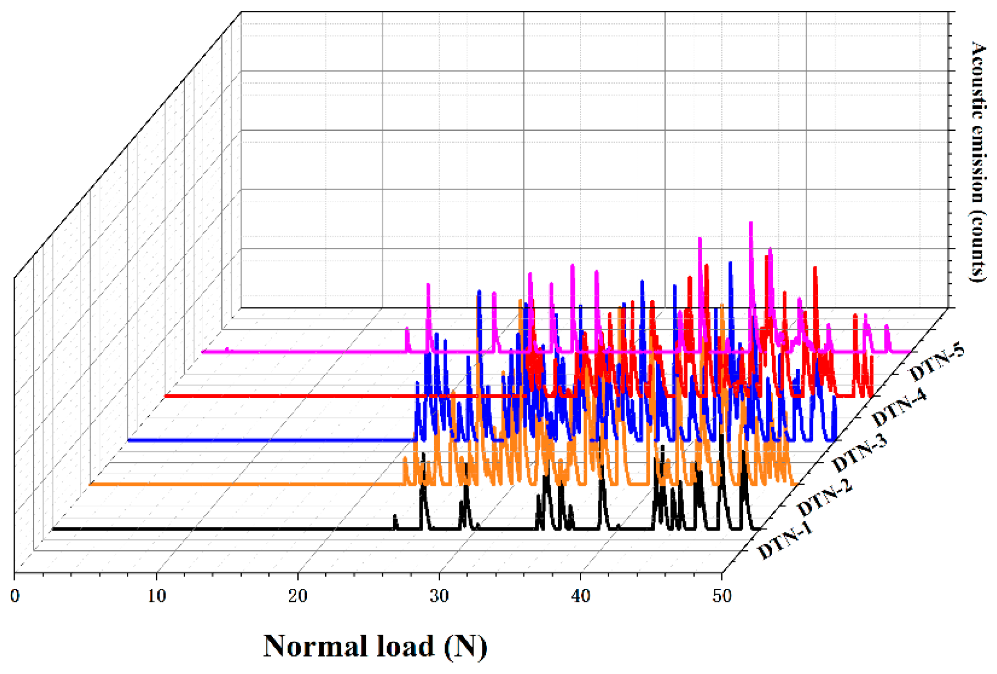
Scratch tests were used to assess the adhesion behavior of Ti-Ni films. The acoustic emission (AE) signal profile can determine the critical normal load (LC). The coating/substrate system’s binding strength can be reliably assessed using the critical normal load (LC) [40,41]. The abrupt increase in AE signal typically denotes that the substrate exposure is a factor in coating failure [42,43]. The scratch acoustic signals and critical loads are shown in Figure 8 and Table 4. The results demonstrate that the film adhesion decreases from 26.1 N to 20.5 N as the Ni target power increases. This demonstrates that a lower Ni target power is advantageous for enhancing film-to-substrate adhesion. With the increase of substrate bias, the adhesion force of the film increases from 25.5 N to 26.1 N and then decreases to 14.4 N. The increase of substrate bias generates internal stresses in the film, and the more minor internal stresses are helpful in reducing the number of defects in the films, while the larger internal stress is likely to cause film peeling.
Figure 9 shows the SEM morphologies of Ti-Ni alloy films after scratch tests. Specifically, the scratch morphology of the Ti-16.5Ni film is selected for detailed analysis. As seen from Figure 9a–e, the width of the scratch becomes wider with the increase of the load. In the load application process, cracks and “jaggedness” appear on both sides of the scratch at the initial stage. The load continues to increase until the substrate is exposed, the central crack of the scratch becomes dense, and the cracks on both sides become loose. The film at the end of the scratch shows adhesive wear with the direction of indenter movement and the film peels off with the indenter.
As seen in Figure 9a, the DTN-1 film starts to fail furthest from the initial position, indicating the best adhesion between it and the substrate, which is consistent with the data in Table 4. At the middle end of the scratch (Figure 9f,g), dense cracking along the scratch direction can be observed due to increasing load, creating cohesion and slight adhesion breakdown in the film. At the end of the scratch (Figure 9h,i), partial peeling of the film surface occurs due to compressive and radial tensile stresses, producing severe adhesive failure. When the load reaches the upper critical load, a large area of peeling occurs in both the center and edge of the scratch, thus exposing the substrate. This emphasizes the importance of controlling the scratch load in order to avoid catastrophic failure and improve the adhesion strength of Ti-Ni films. Overall, the SEM images provide valuable insights into the failure mechanism of Ti-Ni films during scratch tests and can help guide future film development.

4. Conclusions

This work deposited a series of Ti-Ni alloy films on the surface of a 2024 Al alloy using magnetron sputtering. Under different deposition conditions, the films all exhibited a stable BCC structure, mainly composed of β-Ti(Ni). The deposited films showed typical cauliflower-like features on the surface and apparent columnar growth morphology in the cross sections. The particle size increased with the increase of Ni content. The thickness of the film increased and became denser and flatter, and the bias had little effect on the phase composition and thickness of the film. With the increase of Ni target power and bias, the ability of the films to resist plastic deformation decreases after the Ni content exceeds 22%, and the Ti-22.0Ni film layer with bias of −70 V has excellent comprehensive mechanical properties with hardness and modulus of 5.76 GPa and 97.6 GPa, respectively. The overall trend of adhesion strength between Ti-Ni film and substrate decreases with increasing Ni target power and decreasing substrate bias.
In conclusion, thin film deposition provides a practical approach to study the composition–structure–property relationship of Ti-Ni alloys. The adjustment of Ni content by magnetron sputtering allows the study of its effect on phase composition and mechanical properties. This work may provide a reference for guiding the composition design of bulk Ti-Ni alloys, exploring more suitable alloys for medical applications. In future, post-annealing could be employed to stimulate the diffusion between Ti-Ni and Al, thus strengthening the surface of Al alloys.

Author Contributions

Conceptualization, F.Z. and X.Z.; methodology, Y.D.; investigation, X.Z., Y.D., F.Z. and H.M.; data curation, R.Z. and L.W.; writing—original draft preparation, Y.D. and H.M.; writing—review and editing, X.Z., H.M. and F.Z.; supervision, F.Z.; funding acquisition, F.Z. All authors have read and agreed to the published version of the manuscript.

Funding

This research was funded by National Natural Science Foundation of China, grant number No. 51701062.

Institutional Review Board Statement

Not applicable.

Informed Consent Statement

Not applicable.

Data Availability Statement

The data presented in this study are available on request from the corresponding author.

Conflicts of Interest

The authors declare no conflict of interest.

References

  1. Qi, M.H.; Xu, J.L.; Lai, T.; Huang, J.; Ma, Y.C.; Luo, J.M.; Zheng, Y.F. Novel bioactive Ti-Zn alloys with high strength and low modulus for biomedical applications. J. Alloys Compd. 2023, 931, 167555. [Google Scholar] [CrossRef]
  2. Romero-Resendiz, L.; Rossi, M.C.; Seguí-Esquembre, C.; Amigó-Borrás, V. Development of a porous Ti-35Nb-5In alloy with low elastic modulus for biomedical implants. J. Mater. Res. Technol. 2023, 22, 1151–1164. [Google Scholar] [CrossRef]
  3. Wang, W.; Cui, W.; Xiao, Z.; Qin, G. The improved corrosion and wear properties of Ti-Zr based alloys with oxide coating in simulated seawater environment. Surf. Coat. Technol. 2022, 439, 128415. [Google Scholar] [CrossRef]
  4. Zhang, L.C.; Chen, L.Y. A Review on Biomedical Titanium Alloys: Recent Progress and Prospect. Adv. Eng. Mater. 2019, 21, 1801215. [Google Scholar] [CrossRef] [Green Version]
  5. Chen, Q.; Thouas, G.A. Metallic Implant biomaterials. Mater. Sci. Eng. R Rep. 2015, 87, 1–57. [Google Scholar] [CrossRef]
  6. Celesti, C.; Gervasi, T.; Cicero, N.; Giofrè, S.V.; Espro, C.; Piperopoulos, E.; Gabriele, B.; Mancuso, R.; Vecchio, G.L.; Iannazzo, D. Titanium Surface Modification for Implantable Medical Devices with Anti-Bacterial Adhesion Properties. Materials 2022, 15, 3283. [Google Scholar] [CrossRef]
  7. Chawla, V.; Jayaganthan, R.; Chawla, A.K.; Chandra, R. Morphological study of magnetron sputtered Ti thin films on silicon substrate. Mater. Chem. Phys. 2008, 111, 414–418. [Google Scholar] [CrossRef]
  8. Jin, Y.; Wu, W.; Li, L.; Chen, J.; Zhang, J.; Zuo, Y.; Fu, J. Effect of sputtering power on surface topography of dc magnetron sputtered Ti thin films observed by AFM. Appl. Sur. Sci. 2009, 255, 4673–4679. [Google Scholar]
  9. Liu, Y.L.; Fang, L.I.U.; Qian, W.U.; Chen, A.Y.; Xiang, L.I.; Deng, P.A.N. Effect of bias voltage on microstructure and nanomechanical properties of Ti films. Trans. Nonferrous Met. Soc. China 2014, 24, 2870–2876. [Google Scholar] [CrossRef]
  10. Godfroid, T.; Gouttebaron, R.; Dauchot, J.P.; Leclere, P.; Lazzaroni, R.; Hecq, M. Growth of ultrathin Ti films deposited on SnO2 by magnetron sputtering. Thin Solid Film. 2003, 437, 57–62. [Google Scholar] [CrossRef]
  11. Chawla, V.; Jayaganthan, R.; Chawla, A.K.; Chandra, R. Microstructural characterizations of magnetron sputtered Ti films on glass substrate. J. Mater. Process. Technol. 2009, 209, 3444–3451. [Google Scholar] [CrossRef]
  12. Moskovkin, P.; Maszl, C.; Schierholz, R.; Breilmann, W.; Petersen, J.; Pflug, A.; Muller, J.; Raza, M.; Konstantinidis, S.; von Keudell, A.; et al. Link between plasma properties with morphological, structural and mechanical properties of thin Ti films deposited by high power impulse magnetron sputtering. Surf. Coat. Technol. 2021, 418, 127235. [Google Scholar] [CrossRef]
  13. Duan, R.; Li, S.; Cai, B.; Zhu, W.; Ren, F.; Attallah, M.M. A high strength and low modulus metastable β Ti-12Mo-6Zr-2Fe alloy fabricated by laser powder bed fusion in-situ alloying. Addit. Manuf. 2021, 48, 101708. [Google Scholar] [CrossRef]
  14. Prakash, C.; Singh, S.; Ramakrishna, S.; Królczyk, G.; Le, C.H. Microwave sintering of porous Ti–Nb-HA composite with high strength and enhanced bioactivity for implant applications. J. Alloys Compd. 2020, 824, 153774. [Google Scholar] [CrossRef]
  15. Markhoff, J.; Weinmann, M.; Schulze, C.; Bader, R. Influence of different grained powders and pellets made of Niobium and Ti-42Nb on human cell viability. Mater. Sci. Eng. C 2017, 73, 756–766. [Google Scholar] [CrossRef]
  16. Liu, L.; Li, W.; Sun, H.; Wang, G. Effects of Ti Target Purity and Microstructure on Deposition Rate, Microstructure and Properties of Ti Films. Materials 2022, 15, 2661. [Google Scholar] [CrossRef]
  17. Cai, K.; Müller, M.; Bossert, J.; Rechtenbach, A.; Jandt, K.D. Surface structure and composition of flat titanium thin films as a function of film thickness and evaporation rate. Appl. Surf. Sci. 2005, 250, 252–267. [Google Scholar] [CrossRef]
  18. Oya, T.; Kusano, E. Effects of radio-frequency plasma on structure and properties in Ti film deposition by dc and pulsed dc magnetron sputtering. Thin Solid Film. 2009, 517, 5837–5843. [Google Scholar] [CrossRef]
  19. Bălţatu, M.S.; Vizureanu, P.; Goanţă, V.; Ţugui, C.A.; Voiculescu, I. Mechanical Tests for Ti-Based Alloys as New Medical Materials; IOP Publishing: Bristol, UK, 2019; Volume 572, p. 012029. [Google Scholar]
  20. Hsu, H.C.; Wu, S.C.; Chiang, T.Y.; Ho, W.F. Structure and grindability of dental Ti-Cr alloys. J. Alloys Compd. 2009, 476, 817–825. [Google Scholar] [CrossRef]
  21. Xu, W.; Chen, M.; Lu, X.; Zhang, D.W.; Singh, H.P.; Jian-shu, Y.; Pan, Y.; Qu, X.H.; Liu, C.Z. Effects of Mo content on corrosion and tribocorrosion behaviours of Ti-Mo orthopaedic alloys fabricated by powder metallurgy. Corros. Sci. 2020, 168, 108557. [Google Scholar] [CrossRef]
  22. Asl, M.S.; Delbari, S.A.; Azadbeh, M.; Namini, A.S.; Mehrabian, M.; Nguyen, V.H.; Van Le, Q.; Shokouhimehr, M.; Mohammadi, M. Nanoindentational and conventional mechanical properties of spark plasma sintered Ti-Mo alloys. J. Mater. Res. Technol. 2020, 9, 10647–10658. [Google Scholar]
  23. Lee, C.M.; Ju, C.P.; Chern Lin, J.H. Structure-property relationship of cast Ti-Nb alloys. J. Oral. Rehabil. 2022, 29, 314–322. [Google Scholar] [CrossRef]
  24. Dos Santos, R.F.; Rossi, M.C.; Vidilli, A.L.; Borrás, V.A.; Afonso, C.R.M. Assessment of β stabilizers additions on microstructure and properties of as-cast β Ti–Nb based alloys. J. Mater. Res. Technol. 2023, 22, 3511–3524. [Google Scholar] [CrossRef]
  25. Fikeni, L.; Annan, K.A.; Mutombo, K.; Machaka, R. Effect of Nb content on the microstructure and mechanical properties of binary Ti-Nb alloys. Mater. Today 2021, 38, 913–917. [Google Scholar] [CrossRef]
  26. Photiou, D.; Panagiotopoulos, N.T.; Koutsokeras, L.; Evangelakis, G.A.; Constantinides, G. Microstructure and nanomechanical properties of magnetron sputtered Ti-Nb films. Surf. Coat. Technol. 2016, 302, 310–319. [Google Scholar] [CrossRef]
  27. Zhang, F.; Li, C.; Yan, M.; He, J.; Yang, Y.; Yin, F. Microstructure and nanomechanical properties of co-deposited Ti-Cr films prepared by magnetron sputtering. Surf. Coat. Technol. 2017, 325, 636–642. [Google Scholar] [CrossRef]
  28. Liu, G.; Yang, Y.; Luo, X.; Huang, B.; Li, P. The phase, morphology and surface characterization of Ti–Mo alloy films prepared by magnetron sputtering. RSC Adv. 2017, 7, 52595–52603. [Google Scholar] [CrossRef] [Green Version]
  29. Lopes, C.; Vieira, M.; Borges, J.; Fernandes, J.; Rodrigues, M.S.; Alves, E.; Barradas, N.P.; Apreutesei, M.; Steyer, P.; Tavares, C.J.; et al. Multifunctional Ti–Me (Me = Al, Cu) thin film systems for biomedical sensing devices. Vacuum 2015, 122, 353–359. [Google Scholar] [CrossRef]
  30. Stranak, V.; Wulff, H.; Rebl, H.; Zietz, C.; Arndt, K.; Bogdanowicz, R.; Nebe, B.; Bader, R.; Podbielski, A.; Hubicka, Z.; et al. Deposition of thin titanium–copper films with antimicrobial effect by advanced magnetron sputtering methods. Mater. Sci. Eng. C 2011, 31, 1512–1519. [Google Scholar] [CrossRef]
  31. Kobata, J.; Miura, K.I.; Amiya, K.; Fukuda, Y.; Saotome, Y. Nanoimprinting of Ti–Cu-based thin-film metallic glasses deposited by unbalanced magnetron sputtering. J. Alloys Compd. 2017, 707, 132–136. [Google Scholar] [CrossRef]
  32. Wojcieszak, D.; Mazur, M.; Kaczmarek, D.; Mazur, P.; Szponar, B.; Domaradzki, J.; Kepinski, L. Influence of the surface properties on bactericidal and fungicidal activity of magnetron sputtered Ti-Ag and Nb-Ag thin films. Mater. Sci. Eng. C 2016, 62, 86–95. [Google Scholar] [CrossRef] [PubMed]
  33. Frenzel, J.; Wieczorek, A.; Opahle, I.; Maaß, B.; Drautz, R.; Eggeler, G. On the effect of alloy composition on martensite start temperatures and latent heats in Ni–Ti-based shape memory alloys. Acta Mater. 2015, 90, 213–231. [Google Scholar] [CrossRef]
  34. Li, B.Y.; Rong, L.J.; Li, Y.Y.; Gjunter, V.E. Electric resistance phenomena in porous Ni-Ti shape-memory alloys produced by SHS. Scr. Mater. 2001, 44, 823–827. [Google Scholar] [CrossRef]
  35. Yi, X.; Wang, H.; Sun, K.; Sun, B.; Wu, L.; Meng, X.; Gao, Z.; Cai, W. Tailoring of microstructure and martensitic transformation of nanocrystalline Ti–Ni-Hf shape memory thin film. Prog. Nat. Sci.-Mater. 2021, 31, 288–295. [Google Scholar] [CrossRef]
  36. Li, J.; Sun, K.; Li, X.; Meng, X.; Cai, W. High damping performances over wide temperature range in the B doped Ti-Ni shape memory alloys. Mater. Lett. 2023, 330, 133245. [Google Scholar] [CrossRef]
  37. Karki, V.; Debnath, A.K.; Kumar, S.; Bhattacharya, D. Synthesis of co-sputter deposited Ni–Ti thin alloy films and their compositional characterization using depth sensitive techniques. Thin Solid Film. 2020, 697, 137800. [Google Scholar] [CrossRef]
  38. Ren, D.C.; Zhang, H.B.; Liu, Y.J.; Li, S.J.; Jin, W.; Yang, R.; Zhang, L.C. Zhang, Microstructure and properties of equiatomic Ti–Ni alloy fabricated by selective laser melting. Mater. Sci. Eng. A 2020, 771, 138586. [Google Scholar] [CrossRef]
  39. Macías, H.A.; Yate, L.; Coy, L.E.; Olaya, J.J.; Aperador, W. Effect of nitrogen flow ratio on microstructure, mechanical and tribological properties of TiWSiNx thin film deposited by magnetron co-sputtering. Appl. Surf. Sci. 2018, 456, 445–456. [Google Scholar] [CrossRef]
  40. Kabir, M.S.; Munroe, P.; Zhou, Z.; Xie, Z. Study of the structure, properties, scratch resistance and deformation behaviour of graded Cr-CrN-Cr(1-x)AlxN coatings. Ceram. Int. 2018, 44, 11364–11373. [Google Scholar] [CrossRef]
  41. Sha, C.; Zhou, Z.; Xie, Z.; Munroe, P. Scratch response and tribological behaviour of CrAlNiN coatings deposited by closed field unbalanced magnetron sputtering system. Surf. Coat. Technol. 2019, 367, 30–40. [Google Scholar] [CrossRef]
  42. Heinke, W.; Leyland, A.; Matthews, A.; Berg, G.; Friedrich, C.; Broszeit, E. Evaluation of PVD nitride coatings, using impact, scratch and Rockwell-C adhesion tests. Thin Solid Film. 1995, 270, 431–438. [Google Scholar] [CrossRef]
  43. Kim, H.K.; La, J.H.; Kim, K.S.; Lee, S.Y. The effects of the H/E ratio of various Cr–N interlayers on the adhesion strength of CrZrN coatings on tungsten carbide substrates. Surf. Coat. Technol. 2015, 284, 230–234. [Google Scholar] [CrossRef]
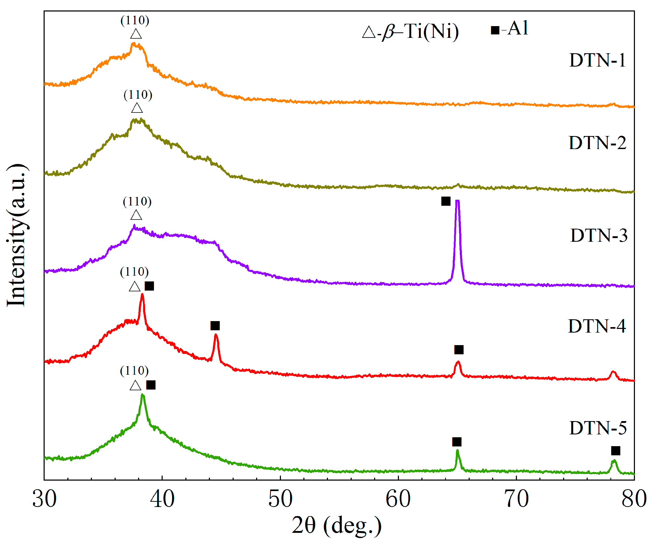
Figure 1. XRD patterns of Ti-Ni film deposited with different Ni target power and bias.
Coatings 13 00524 g001
Figure 2. Surface morphology of Ti-Ni films deposited at different Ni target powers and substrate bias. (a,f) DTN-1; (b,g) DTN-2; (c,h) DTN-3; (d,i) DTN-4; (e,j) DTN-5.
Coatings 13 00524 g002
Figure 3. Particle size of Ti-Ni films deposited under different Ni target power and bias.
Coatings 13 00524 g003
Figure 4. Element distribution of Ti-Ni films deposited at different Ni target power and bias pressures: (a) DTN-1, (b) DTN-3, (c) DTN-5.
Coatings 13 00524 g004
Figure 5. Cross-sectional morphology of Ti-Ni films deposited at different Ni target powers and bias: (a) DTN-1; (b) DTN-2; (c) DTN-3; (d) DTN-4; (e) DTN-5.
Coatings 13 00524 g005
Figure 6. Fracture morphology of Ti-Ni films deposited at different Ni target power and bias: (a) DTN-1; (b) DTN-2; (c) DTN-3; (d) DTN-4; (e) DTN-5.
Coatings 13 00524 g006
Figure 7. Nanoindentation results of Ti-Ni films deposited at different Ni target powers and bias. (a) Hardness and modulus, (b) load-displacement curves.
Coatings 13 00524 g007
Figure 8. Schematic diagram of the acoustic signals of Ti-Ni films deposited with different Ni target power and bias.
Coatings 13 00524 g008
Figure 9. Scratch morphology of Ti-Ni films deposited with different Ni target powers and bias: (a) DTN-1, (b) DTN-2, (c) DTN-3, (d) DTN-4, (e) DTN-5, (f,g) DTN-1 mid-scratch, (h,i) DTN-1 end-scratch.
Coatings 13 00524 g009
Table 1. Parameters of magnetron sputtering deposition of Ti-Ni films.
Process ParameterUnitValue
Background pressurePa4 × 10−3
Argon fluxsccm16
Ti target powerkW1.5
Ni target powerkW0.1, 0.15, 0.25
Bias voltageV−10, −70, −110
Sputtering timemin120
Sputtering pressurePa0.2–0.3
Target-substrate distancemm70
Table 2. EDS results of Ti-Ni films deposited at different Ni target power and substrate bias.
Films/ElementsTi (at. %)Ni (at. %)
DTN-183.516.5
DTN-278.022.0
DTN-366.533.5
DTN-483.416.6
DTN-583.716.3
Table 3. Calculated nanoindentation results of Ti-Ni films.
SampleH (GPa)E (GPa)H/E
(×10−2)
H3/E2
(×10−2)
Wt (nJ)Wp (nJ)ηp
2024Al1.57821.910.0510.659.30.87
DTN-14.45875.121.176.174.590.69
DTN-25.1797.65.291.146.45.030.79
DTN-34.1890.54.620.897.475.590.75
DTN-44.7194.54.981.177.095.370.76
DTN-54.89965.101.276.114.690.77
Table 4. Critical loads of Ti-Ni films deposited at different Ni target powers and bias pressures.
SampleCritical Load (N)
DTN-126.1
DTN-222.2
DTN-320.5
DTN-425.5
DTN-514.4
Disclaimer/Publisher’s Note: The statements, opinions and data contained in all publications are solely those of the individual author(s) and contributor(s) and not of MDPI and/or the editor(s). MDPI and/or the editor(s) disclaim responsibility for any injury to people or property resulting from any ideas, methods, instructions or products referred to in the content.