Article

Comparative Analysis of Strength Fatigue Properties and Abrasive Wear Resistance for a New Composition of Polymer Concrete Coated with Metal Alloy Powders

1
Department of Technological Equipment, Mechanical Engineering and Standardization, Abylkas Saginov Karaganda Technical University, Karaganda 100027, Kazakhstan
2
Institute of Machine Design, Faculty of Mechanical Engineering, Poznan University of Technology, 60-965 Poznan, Poland
3
Department of Mechatronics, Robotics and Digital Manufacturing, Faculty of Mechanics, Vilnius Gediminas Technical University, LT-10223 Vilnius, Lithuania
4
Faculty of Chemical Technology, Poznan University of Technology, 60-965 Poznan, Poland
*
Authors to whom correspondence should be addressed.
Coatings 2023, 13(3), 586; https://doi.org/10.3390/coatings13030586
Submission received: 30 December 2022 / Revised: 25 February 2023 / Accepted: 2 March 2023 / Published: 8 March 2023
(This article belongs to the Special Issue Smart Coatings)

Abstract

:
The possibility of using powder spraying to improve the strength properties of polymer concrete products has been studied. Different compositions of polymer concrete mixtures have been compared and analyzed in order to find out the adhesive and cohesive properties of coatings. An analysis of the stress-strain state under static loads has been carried out. To improve the tribological properties and wear resistance of critical parts of metal-cutting machine tools, such as beds, it is proposed to spray polymer concrete surfaces using the gas-thermal method. Two types of powder mixtures for spraying have been compared, and the adhesive properties of the analyzed coatings have been considered. The finite element method was used for the calculation of the abrasion resistance of polymer concrete models according to the proposed modification of Ni-7Cr-3Fe + 60% WC coating composition, which showed that the use of gas-thermal coating for polymer concrete is justified. Based on a simulation of adhesive peeling strength, it can be concluded that the wear coefficient of the coated sample is quite large. Under the impact of amplitude loads applied during 5 × 10⁶ loading cycles with a high degree of wear equal to 1.5, the sample showed high safety margins equal to 0.67. The presence of a sprayed layer prevents the concentration of internal stresses in the area of polymer concrete, taking over the resulting stresses under an external force caused by the mechanical properties of the materials, thereby increasing the service life of a manufactured part.

1. Introduction

Today, the requirements for machine tool performance are getting higher and higher because of the need to obtain more accurate and high-quality products. This is due to the fact that the performance of a machine depends on its individual elements, which are subjected to various loads during operation. Thus, the demand for new technologies and materials to manufacture machine tool elements has increased.
Such elements of the machine as the bed, the base, the frames, etc. are subjected to the greatest loads. Basically, these elements are composed of cast iron and steel. However, elements composed of steel and cast iron do not meet the latest requirements, as they exhibit low vibration resistance and cannot maintain dimensional stability for a long time [1]. Thus, new materials, that is, composite materials [2,3,4,5,6,7], are a promising alternative. It has been established that manufacturing a bed from polymer concrete increases vibration resistance by 1.4 times. Additionally, the machine tool metal consumption is reduced by 60% [8].
The type of composite material, such as a mineral-polymer composite, which consists of a stone base and synthetic resin as a binder, has become widespread in the field of machine tool construction [9]. Polymer concrete differs from cement concrete in that, in the presence of a binder, a polymer is used instead of cement [10,11,12,13,14,15]. Therefore, it can be said that the abrasion strength of polymer concrete depends on many parameters. Different structures obtained from different resins and fillers have different properties. To obtain a composite material that can meet the conditions and requirements of the application, the parameters determining the properties of the polymer concrete need to be carefully examined and tested.
From a technological point of view, composite materials make it possible to perform high-precision casting of parts that often do not require mechanical or heat treatment, which significantly reduces the time of manufacturing large elements [16]. Therefore, in a serial production, the period needed to manufacture parts using composites and transfer them to the next production stage is 3–10 days, depending on the dimensions of the parts [17].
The use of polymer concrete parts in a machine carrier system helps to increase its productivity, reduce energy costs and the production time, and increases the accuracy and purity of the manufactured products [18].
Studying the fatigue behavior of a material that is to be used in structures, machine parts, etc., with high cyclic loading is of great importance [19]. According to the results of the research on the polymer concrete properties provided by the literature [20,21], polymer concrete, as compared to metal materials, is characterized by significantly lower fatigue strength.
However, there are only a few studies of the fatigue properties of polymer concrete used in machine tools as supporting structures, as it is difficult to predict the strength of composite materials due to their physical nature.
In addition, a wide use of polymer composite materials in the machine tool industry is limited by the complexity of their stress-strain state characteristics under cyclic loading. Therefore, the issue of the fatigue strength of polymer concrete used in metal-cutting machine frames exposed to cyclic loading is a serious scientific problem.
According to the authors of [22,23], the fatigue strength of polymer composite materials under cyclical loading is much more intensely affected. Residual deformations and microdestructions occur under the impact of loading forces, which have an adverse effect on the long-term strength limit of the weakest particles. Destruction occurs upon removing the load, not upon loading, because the removal of the load from particles that have received irreversible direct sign deformations causes stresses of the opposite sign. If stresses exceed the ultimate tensile strength, a particle will be destroyed, and microfractures will appear all over the material. To prevent this, it is proposed to apply a modified surface to the polymer-concrete frame using the gas-thermal method.
Under the prolonged impact of cyclic loads, the structure of polymer composite materials changes due to local self-heating at the tips of growing submicrocracks and subsequent changes in the material’s elastic hysteresis properties [24,25].
It was found that for a frame model composed of polymer concrete with thermally sprayed guides, the strength and dynamic characteristics of polymer concrete increased [2]. However, according to the study of adhesion between the coating material and polymer, the concrete surface revealed that not all the materials of the polymer concrete surface were laid on it in an even layer and with the required bonding strength.
The purpose of the article is to analyze the impact of the polymer concrete composition and the composition of the powder coating mixtures thermally sprayed on the surface layer of the polymer concrete by reducing internal stresses and increasing the fatigue strength of the machine tool-supporting structures. In addition, an analysis of the coating’s resistance to external cyclical loads was carried out. The authors of the article aimed at determining the optimal composition of polymer concrete in combination with a powder composition sprayed on a single sample of the guide sections of a machine support structure.

2. Materials and Methods

2.1. Study of the Mechanical Properties of Polymer Concrete of Various Grades

2.1.1. Sample Preparation

To meet the research goal, various optimal compositions of this composite material were identified based on a theoretical analysis of its polymer-concrete characteristics.
Many authors [26,27,28] who study the nature and structure of polymer concrete have considered mainly two areas of research:
the effect of changing the composition of the polymer-concrete material on its mechanical properties;
the effect of changing polymer-concrete variables on its mechanical properties;
to identify the best compositions of polymer-concrete mixtures for manufacturing machine frames; single samples of two compositions were used (Table 1 and Table 2);
polymer-concrete samples with different fillers were prepared; however, both were based on quartz sand of the same fraction. The following additives were used:
  • MMA compound is an elastic compound with the following advantages: resistance to vibration and movement of the substrate, good wear resistance, high impact resistance, and resistant to many chemicals designed for heavy loads [29].
  • Polyethylene-polyamine (PEPA) is a hardener that provides higher physical and mechanical properties, greater heat resistance, and low exothermicity [30].
  • Epoxy resin is characterized by high hardness, dielectric properties, resistant to aggressive environments, and does not cause corrosion of materials in contact with it [31,32].
  • FA resin (FAM) is a furan resin resistant to temperatures, acids, and alkalis [33,34].
Preparing a single sample (Figure 1 and Figure 2) with the use of both mixture compositions includes the following stages:
(1)
mixing of components;
(2)
casting into a special mold;
(3)
compacting on a vibro-table;
(4)
finishing operations.
The manufacturing process was identical for both samples. The components of the polymer-concrete mixtures were selected according to economic factors, so that the bed would not be too expensive.

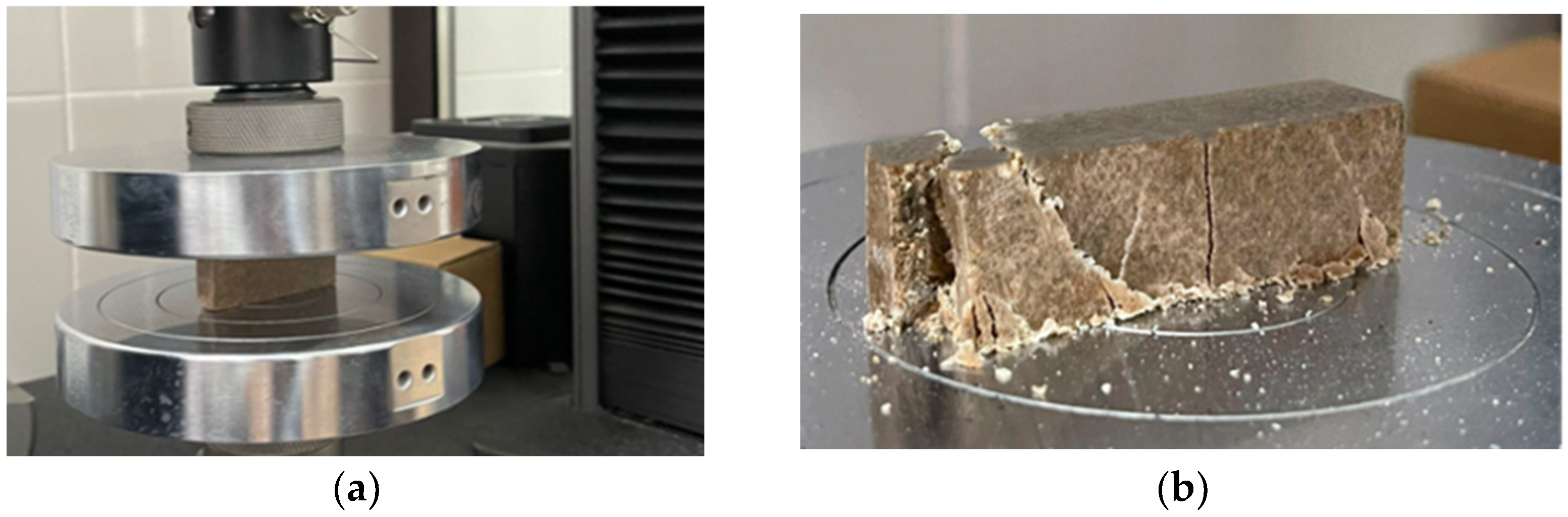
2.1.2. Conducting an Experiment

To study the strength properties of the obtained samples, compression, tension, fatigue strength, and residual stresses, a static analysis of the samples was carried out by the finite element method in the BETA CAE SYSTEM, ABAQUS environment. The unified and completely integrated ANSA/MΕΤA package is the preferred choice for modeling and strength calculations for pre- and postprocessing, as well as for solving some unique finite element modeling problems [35].
During the simulation, the boundary conditions were as follows:
(1)
the values of gravity and axial force in the range of 50 kN;
(2)
geometric parameters of the sample—200 × 500 × 100 mm;
(3)
sample compositions according to Table 1 and Table 2;
(4)
the ambient temperature was 30 °C.
An important aspect of the simulation studies was generating the correct finite element mesh (FEM). A standard procedure is followed when creating a computational model of representative blocks. Second-order three-dimensional pyramidal elements were used in the discretization process. To accurately represent the distribution of internal stresses in blocks under the impact of external forces, it is necessary to pay attention to the distribution of the finite element mesh. Figure 3 and Figure 4 show the finite element mesh applied to polymer-concrete samples. The unsprayed polymer sample was divided into 67,872 nodes and 62,000 elements, and the sprayed polymer sample was divided into 72,114 nodes and 66,000 elements.
The results of the analysis are shown in Figure 5 and Figure 6.
The concentration of internal stresses occurring in the outer layers of the model, that is, in the corners, of the rigidly fixed system, is 20.95 MPa in Figure 5 and 19.04 MPa in Figure 6.
The input data were the properties of the materials used for the analysis of the sample fatigue strength. The mechanical properties of the samples are presented in Table 3.
Based on the calculations, the following parameters characterizing the fatigue strength of the studied polymer-concrete mixture samples, shown in Table 4 and Table 5, were obtained.
To analyze fatigue strength and the nature of internal stresses in the samples, a calculation method [36] was used, according to which the readings of the internal stress characteristics were taken from two points, taking into account the distance between them, and calculating the stress gradient (Figure 7).
Among all the available loads, the amplitude (alternating) loads are the worst, so the effect of these loads on the fatigue strength parameters of the model components is obvious. On the basis of this effect, the model sensitivity to amplitude loads, as well as the fatigue strength of the components, were calculated. The calculation results are presented in Table 6.
The effect of the number of working cycles on the strength of the model is studied in Table 7. The initial loading conditions for the two models are the average value of the loading cycles of at least 4 × 10⁶. Let us consider the worst case by increasing the value of duty cycles by 25%.
Table 8 presents the results of the worst-case operating conditions of polymer concrete without performing supporting operations (cleaning and additional reinforcement) with the imposition of large amplitude loads and a high degree of wear.
As a result of the fatigue strength, it can be concluded that the wear coefficient of both samples is quite large. Under the impact of amplitude loads, for 5 × 10⁶ load cycles with a high wear degree equal to 1.5; the samples showed high strength reserves equal to 21% for the sample of polymer concrete No. 23, and 14% for the sample of polymer concrete No. 15.
Based on the static analysis of the loading of the samples, the best result was found for the values and nature of internal stress propagation in the model of a single sample under the impact of gravity, axial force of 100 kN, with the highest wear equal to 1.5 at 5 × 10⁶ loading cycles. The polymer-concrete variant with composition No. 23 showed the best values. This polymer-concrete composition is used for further research and mathematical analysis.

2.2. Experiments on the Deposition of Coatings and Studying the Properties of the Obtained Layers

In order to determine the adhesion properties of the coatings, the following two variants of powder alloys were selected for application (Figure 8):
(1)
META Ceram 28010 (Castolin Eutectic, Dublin, Ireland);
(2)
Eutalloy SF PE 8215 (Castolin Eutectic, Dublin, Ireland).
The data obtained from the experiment, and data concerning the metal-cutting machine frame geometry were used for the calculation of the optimal parameters of the spraying process for the selected powder alloys. Polymer-concrete model No. 23 with applied experimental coatings was used as a sample. The parameters of the deposition process in the developed installation were taken from previous studies [37].
The sprayed sample part was cooled in air at a temperature of 20 ± 5 degrees in a well-ventilated room.
The coating based on the MetaCeram 28010. Cr2O3 powder alloy was selected because, after application, the coating had the following properties:
low electrical conductivity;
high resistance to wear;
high hardness;
high protection against corrosion;
low coefficient of friction.
This powder has the following characteristics: the resulting coating hardness is 2200 HV10, the maximum operating temperature is 550 °C, the grain size is 16–64 microns.
Figure 9 shows the microstructure of the Cr2O3 coating. Based on the application of the experimental coating of Cr2O3, it was found that the layered structure had a small amount of large pores. Such pores can occur during the preparation of thin sections in the chipping process. Such elements arise due to insufficient heating during spraying, as a result of which rather large coating elements (pulls) can separate during cutting. A more detailed description of the coating is presented in Table 9.
The coating based on SF PE 8215—Ni-7Cr-3Fe + 60% WC powder alloy, consisting of tungsten carbide and other mixtures is intended for coatings to provide properties such as hardness and high abrasive wear.
This powder has the following major characteristics: coating hardness is 950 HV10, the maximum operating temperature is 750 °C, the grain size is 16–64 microns.
Figure 10 shows the microstructure of the Ni-7Cr-3Fe + 60% WC coating, no gaps or deformed particles were found in the coating, and there was almost no porosity. Figure 8 shows the formation of a uniform layer of various particles that are in the solid state and, subsequently, have high cohesive strength. It should also be noted that in the nickel matrix, the carbide particles are embedded quite firmly. A more detailed description of the coating is presented in Table 10.
Based on the results obtained, it can be concluded that the Ni-7Cr-3Fe + 60% WC coating has the best strength characteristics. It should also be noted that the porosity of the coating that is absent in the Ni-7Cr-3Fe + 60% WC is of small importance.
To study the tribological properties of the coatings, it is necessary to carry out an evaluation of the strength properties of the coating material, depending on the type of destruction and according to the power and geometric parameters of the load application site, as well as the distribution of internal stresses. A static analysis of the samples was carried out by the finite element method in the BETA CAE SYSTEM, ABAQUS environment. During the simulation, the boundary conditions were as follows:
(1)
the values of gravity and axial force in the range of 50 kN;
(2)
the geometric parameters of the sample—200 × 500 × 100 mm;
(3)
the ambient temperature was 20 ± 5 °C.
(4)
the sample compositions according to Table 2.
(5)
the composition of the coating according to Table 9 and Table 10.
Based on the results of the static analysis (Figure 11), No. 23 polymer concrete in Ni-7Cr-3Fe + 60% WC (V02) was selected as the base material for the tests, since under the impact of gravity and an axial force of 100 kN, the smallest internal stresses occur in the model with a value of 11.12 MPa in the sprayed layer and 7.23 MPa in the predominant part of the polymer concrete. The results of the static analysis of polymer concrete No. 23 in its configuration with sprayed Cr2O3 (V04) in Figure 12 showed a satisfactory result; no further modeling was required.
The presence of a sprayed layer prevents the concentration of internal stresses in the area of polymer concrete by taking over the stresses caused by the impact of external forces due to the material’s mechanical properties, thereby increasing the service life of the manufactured part.
Thus, for the sample composed of polymer-concrete composition No. 23 with the Ni-7Cr-3Fe + 60% WC thermal coating, the internal stress was 11.12 MPa, while for the sample composed of polymer-concrete composition No. 23 with the Cr2O3 thermal coating, the total stress was 17.65 MPa under the same loading conditions.
In this case, it can be concluded that the strength characteristics of the Ni-7Cr-3Fe + 60% WC coating are higher than those of a similar sample. Therefore, for further mathematical analysis of the adhesive strength of the coating, a sample with the above composition (Table 11) and with the following physical and mechanical properties (Table 12) should be used.
Based on the calculations, the following parameters characterizing the adhesion strength of the coating sample (presented in Table 12, Table 13, Table 14 and Table 15) were obtained.
Thus, it can be concluded that the adhesive strength of the Ni-7Cr-3Fe + 60% WC coating composition obtained by thermal spraying on a preprepared polymer concrete is equal to 100 MPa (Table 2) for cyclic alternating loads and for the same number of cycles (5 × 10⁶), in contrast to the sample composed of polymer concrete of the same composition but without a coating (36 MPa). When amplitude loads are applied to the samples, it can be concluded that a sample with a thermal coating has a 12% greater margin of wear resistance than a similar sample with no coating.

3. Results

To calibrate the results of a mathematical analysis carried out using the BETA CAE SYSTEM, the ABAQUS software package, a compression test of a prototype (46 × 10 × 20 mm) composed of polymer concrete No. 23 with a gas-thermal coating of Ni-7Cr-3Fe + 60% WC was carried out. The experiment was carried out on a small sample since it is economically beneficial to avoid an error affecting large material models. The experiment was carried out using the technical equipment of the INSTRON 5980 universal testing system.
The experiment was carried out under normal conditions, with the ambient temperature being 25 °C and the humidity being 60%. Using the INSTRON 5980 technical equipment of the Universal Testing System, an axial force of 93.94 kN was applied, at which point the sample structure was destroyed (Figure 13). The sample failure graph is shown in Figure 14, and the descriptions of the failure graph are presented in Table 16.
After the compression test, a similar test was carried out using the BETA CAE SYSTEM software (V22.03), ABAQUS. The experiment showed that for a sample with dimensions of 46 × 10 × 20 mm, with a load of 93.94 kN applied, stress equal to 152.00 MPa arose on the surface of the sprayed layer and 108.39 MPa on the polymer-concrete structure, which led to the destruction of the sample (Figure 15).
The experiment was conducted for known parameters of polymer concrete and tensile strength (120 MPa). Tensile strength and physicomechanical parameters of the sprayed layer Ni-7Cr-3Fe + 60% WC were found.
Thus, it can be concluded that, for the same conditions as those for full-scale mathematical experiments, the results for a sample of 200 × 500 × 100 mm are valid.

4. Discussion

When studying the test frequency effect, it must be concluded that test frequency (load cycles) should be used as a parameter for fatigue testing of the polymer concrete.
An analysis of the literature shows that it is quite difficult to predict the fatigue strength of polymer concrete under cyclic loading, and the available methods for materials with crystalline structures and polymers are not always applicable to them.
In the course of the literature’s theoretical analysis, it was found that there were a few sources dealing with the analysis of the fatigue strength of polymer concrete used for manufacturing machine tool beds to increase the wear resistance of their guides.
Studies have shown that destruction occurs upon removing the load, not during loading, because the removal of the load from the particles that have received irreversible direct sign deformations causes stresses of the opposite sign. If the stresses exceed the ultimate tensile strength, the particles will be destroyed and microfractures will appear all over the material. To prevent this, it is proposed to apply a modified coating on the surface of the frame made of polymer concrete by the gas-thermal method in appropriate modes [37]. To determine the optimal technological parameters for coating application by the gas-thermal method, the authors have developed a special software that allows, in the shortest possible time, to use input data (design parameters of the part and part material) to determine the main technological parameters of the process (sputtering distance, linear speed, thickness of the sprayed coating, number of passes, and many others).
Previously, the authors conducted research on the practical application of the thermal spraying method on the guide frame made of polymer concrete [8]. It was found that for a model frame made of polymer concrete with thermally sprayed guides, the internal stress was 9.8 MPa and the displacement was 0.5 mm, while for a structure made of polymer concrete without spraying, the total stress was 12.5 Mpa, and the deformation was 0.65 mm under the same loading conditions.
To identify the best compositions of polymer concrete mixtures for manufacturing metal cutting machine frames in terms of cyclic loads, only two compositions were made. Based on the fatigue strength simulation and the distribution of internal stresses, it can be concluded that the wear coefficient of both samples is quite large. Under the impact of amplitude loads during 5 × 10⁶ loading cycles with a high degree of wear equal to 1.5, the samples showed high strength factors equal to 21% for the polymer concrete sample No. 23, and 14% for the polymer concrete sample No. 15.
To reduce adverse internal stresses and increase the fatigue strength, a method of applying thermal spraying was studied on the surface of the guides. It was established that for the sample made of polymer concrete composition No. 23 with a thermal coating of Ni-7Cr-3Fe + 60% WC, the internal stress was 11.12 MPa, while for the large polymer concrete composition No. 23 with a Cr2O3, thermal coating, the total stress was 17.65 MPa under the same loading conditions. In this case, it can be concluded that the peeling strength characteristics of the Ni-7Cr-3Fe + 60% WC coating are higher than those of a similar sample.
The adhesive strength of the coating with Ni-7Cr-3Fe + 60% WC obtained by thermal spraying on a preprepared polymer concrete surface, alternating an optimal composition with cyclic loads with the same number of cycles (5 × 10⁶), was 100 MPa, in contrast to the sample made of polymer concrete of the same composition but with no coating (36 MPa). When amplitude loads are applied to samples, it can be concluded that a sample with a thermal coating has a 12% higher margin of wear resistance than a similar sample with no coating.
The presence of the modified coating layer was found to prevent the concentration of internal stresses in the polymer concrete area by taking over the resulting stresses under the impact of an external force due to the mechanical properties of the materials, thereby increasing the service life of the manufactured part.

5. Conclusions

Selecting the composition of polymer concrete and the composition of mixtures of powder coatings used on the surface layer for applications in machine structures, e.g., support frames of machine tools, requires taking into account many factors, such as internal stresses and fatigue strength. The use of coatings on polymer concrete provides a composite material with various properties depending on the materials used.
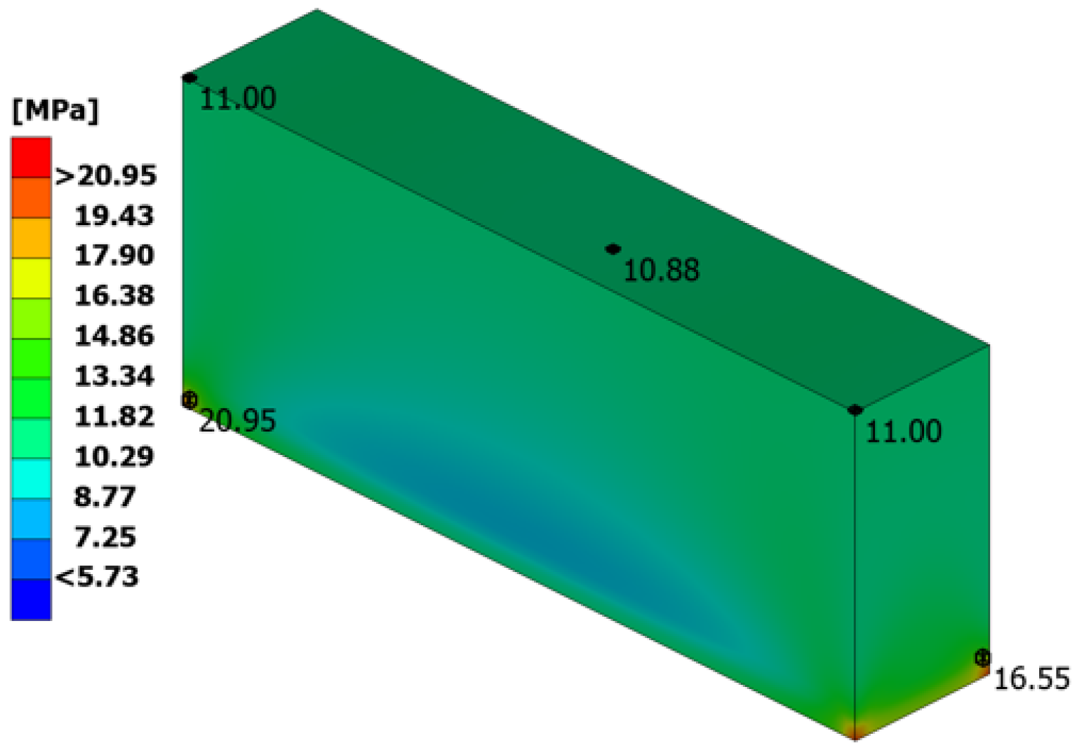
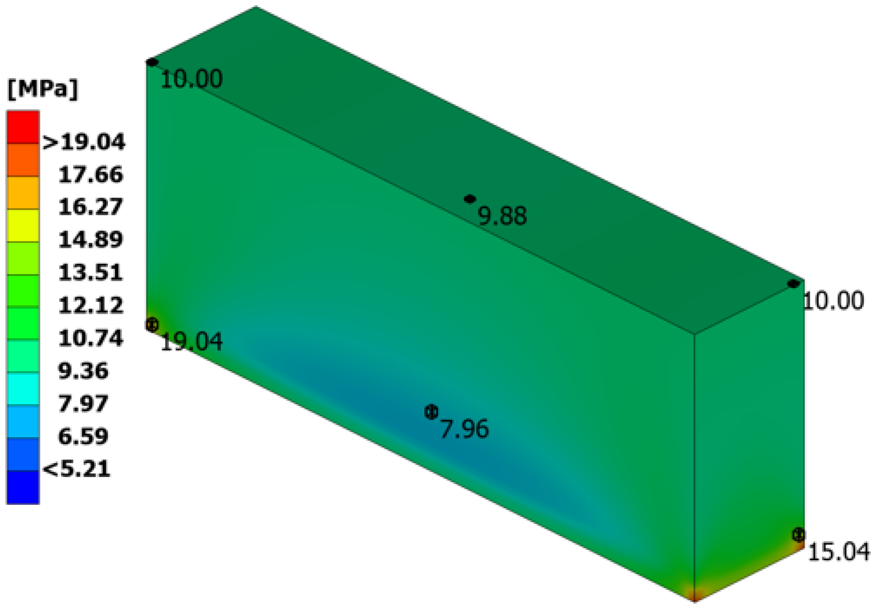
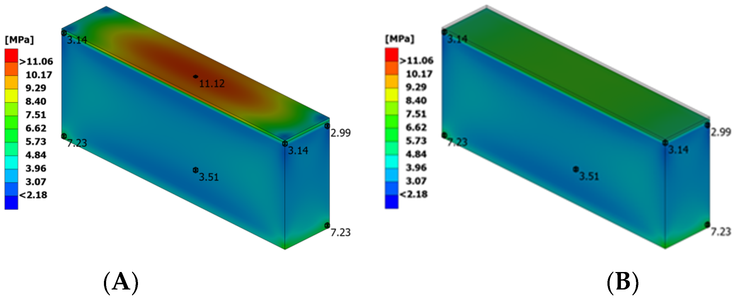
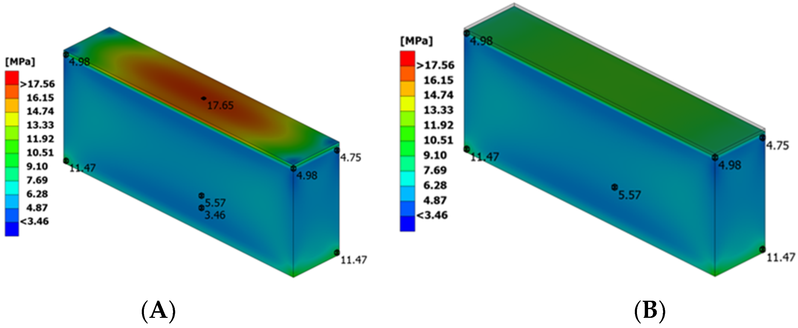
  • The use of thermally sprayed surfaces on polymer concrete machine tool frames can reduce internal stresses by approximately 21.6% and increase fatigue strength from 14% to 21% (depending on the type of composition).
  • When comparing the impacts of the use of 7Cr-3Fe + 60% WC and Cr2O3 thermal coatings, it can be seen that the first can be characterized by a greater reduction in internal stresses (11.12 MPa and 17.65 MPa, respectively) of 37%. Polymer concrete without Ni-7Cr-3Fe + 60% WC coating is characterized by a lower fatigue strength of 63% (36 MPa and 100 MPa, respectively).
  • The applied coating also increased wear resistance by 12%.
The composition of polymer concrete with Ni-7Cr-3Fe + 60% WC coating presented in the article is the most advantageous in terms of durability and the strength of machine tool frames of all the tests carried out for this stage. Further studies should be carried out on machine tools under real conditions, as the presented studies include experimental tests and numerical research.

Author Contributions

Conceptualization T.N.; supervision, V.T. and Ł.G.; methodology, T.N., A.B. and Ł.G.; formal analysis, D.Z. and Ł.G.; investigation, G.A. and A.B.; writing—original draft preparation, T.N., A.B., Ł.G., Ł.W. and G.A.; writing—review and editing, D.E., Ł.G., V.Y., Ł.W., B.W., M.R. and T.N.; project administration, T.N.; funding acquisition, D.E., Ł.G. and T.N. All authors have read and agreed to the published version of the manuscript.

Funding

The Science Committee of the Ministry of Education and Science of the Republic of Kazakhstan IRN: project No. AP08856371.

Institutional Review Board Statement

Not applicable.

Informed Consent Statement

Not applicable.

Data Availability Statement

Not applicable.

Conflicts of Interest

The authors declare no conflict of interest.

References

  1. Haddad, H.; Al Kobaisi, M. Optimization of the Polymer Concrete Used for Manufacturing Bases for Precision Tool Machines. Compos. Part B Eng. 2012, 43, 3061–3068. [Google Scholar] [CrossRef]
  2. Shafei, B.; Kazemian, M.; Dopko, M.; Najimi, M. State-of-the-Art Review of Capabilities and Limitations of Polymer and Glass Fibers Used for Fiber-Reinforced Concrete. Materials 2021, 14, 409. [Google Scholar] [CrossRef]
  3. Shiravi, M.M.; Eftekhar, M.R.; Hamadani, A.Z. Establishing an empirical relation between the compressive, tensile, and flexural strengths of polymer concrete. Innov. Infrastruct. Solut. 2023, 8, 87. [Google Scholar] [CrossRef]
  4. Struk, V.A.; Kravchenko, V.I.; Kostyukovich, G.A.; Skaskevich, A.A. Composite polymeric coatings for reconditioning friction units of machines and process equipment. Trenie Iznos 2002, 23, 329–333. [Google Scholar]
  5. Vipulanandan, C.; Paul, E. Characterisation of polyester polymer and polymer concrete. J. Mater. Civ. Eng. 1993, 5, 62–82. [Google Scholar] [CrossRef]
  6. Sanaei Ataabadi, H.; Arash Sedaghatdoost, A.; Rahmani, H.; Zare, A. Microstructural characterization and mechanical properties of lightweight polymer concrete exposed to elevated temperatures. Constr. Build. Mater. 2021, 311, 125293. [Google Scholar] [CrossRef]
  7. Jafari, K.; Tabatabaeian, M.; Joshaghani, A.; Ozbakkaloglu, T. Optimizing the mixture design of polymer concrete: An experimental investigation. Constr. Build. Mater. 2018, 167, 185–196. [Google Scholar] [CrossRef]
  8. Zhetessova, G.; Nikonova, T.; Gierz, Ł.; Berg, A.; Yurchenko, V.; Zharkevich, O.; Alexey, K. A Comparative Analysis of the Dynamic Strength Properties of the Long Guides of Intelligent Machines for a New Method of the Thermal Spraying of Polymer Concrete. Appl. Sci. 2022, 12, 10376. [Google Scholar] [CrossRef]
  9. Ergun, A.; Mahmut, N.G. Usability of Polymer Concrete as a Machine-Making Material Regarding Fatigue Strength. World J. Eng. Technol. 2013, 1, 59–64. [Google Scholar] [CrossRef] [Green Version]
  10. Abbasnejadfard, M.; Morteza Bastami, M.; Hashemi, S.-A. Experimental investigation on the stress-strain behavior of unsaturated polyester polymer concrete subjected to monotonic and cyclic loadings. J. Build. Eng. 2022, 48, 103966. [Google Scholar] [CrossRef]
  11. Rebeiz, K.S. Precast use of polymer concrete using unsaturated polyester resin based on reccles PET waste. Constr. Build. Mater. 1996, 10, 215–220. [Google Scholar] [CrossRef]
  12. Vipulanandan, C.; Mebarkia, S. Aggregates, fibers and coupling agents in polymer concrete. In Proceedings of the 1st Materials Engineering Conference, Denver, CO, USA, 13–15 August 1990; pp. 785–794. [Google Scholar]
  13. Okada, K.; Yonezawa, T. Thermo dependent properties of polyester resin concrete. J. Soc. Mater. Sci. Jpn. 1975, 24, 394–400. [Google Scholar] [CrossRef]
  14. Vipulanandan, C.; Dharmarajan, N.; Ching, E. Mechanical behaviour of polymer concrete systems. Mater. Struct. 1988, 21, 268–277. [Google Scholar] [CrossRef]
  15. Bruni, C.; Forcellese, A.; Gabrielli, F.; Simoncini, M. Hard turning of an alloy steel on a machine tool with a polymer concrete bed. J. Mater. Process. Technol. 2008, 202, 493–499. [Google Scholar] [CrossRef]
  16. Vrtanoski, G.; Dukovski, V. Design of polymer concrete main spindle housing for CNC lathe. In Proceedings of the 13th International Scientific Conference on Achievements of Mechanical and Materials Engineering, Gliwice, Poland, 13–16 June 2005; pp. 696–698. [Google Scholar]
  17. Cortes, F.; Castillo, G. Comparison between the dynamical properties of polymer concrete and grey cast iron. Mater. Des. 2007, 28, 1461–1466. [Google Scholar] [CrossRef]
  18. Suh, J.D.; Lee, D.G. Design and manufacture of hybrid polymer concrete bed for high-speed CNC milling machine. Int. J. Mech. Mater. Des. 2008, 4, 113–121. [Google Scholar] [CrossRef]
  19. Sezan, O. Investigation of vibration damping on polymer concrete with polyester resin. Cem. Concr. Res. 2000, 30, 171–174. [Google Scholar] [CrossRef]
  20. Suh, J.D.; Lee, D.G.; Kegg, R. Composite Machine Tool Structures for High Speed Milling Machines. CIRP Ann. Manuf. Technol. 2002, 51, 285–288. [Google Scholar] [CrossRef]
  21. Yin, J.; Zhang, J.; Wang, W. Effective resin content and its effect on the overall performance of polymer concrete for precision machine tools. Constr. Build. Mater. 2019, 222, 203–212. [Google Scholar] [CrossRef]
  22. Hassani Niaki, M.; Fereidoon, A.; Ghorbanzadeh Ahangari, M. Mechanical properties of epoxy/basalt polymer concrete: Experimental and analytical study. Struct. Concr. 2018, 19, 366–373. [Google Scholar] [CrossRef]
  23. Möhring, H.-C. Composites in Production Machines. Procedia CIRP 2017, 66, 2–9. [Google Scholar] [CrossRef]
  24. Mula, V.R.; Ramachandran, A.; Pudukarai Ramasamy, T. A review on epoxy granite reinforced polymer composites in machine tool structures—Static, dynamic and thermal characteristics. Polym. Compos. 2023; Early View. [Google Scholar] [CrossRef]
  25. Mayr, J.; Jedrzejewski, J.; Uhlmann, E.; Donmez, M.A.; Knapp, W.; Hartig, F.; Wendt, K.; Moriwaki, T.; Shore, P.; Schmitt, R.; et al. Thermal issues in machine tools. CIRP Ann. Manuf. Technol. 2012, 61, 771–791. [Google Scholar] [CrossRef] [Green Version]
  26. Hameed, A.M.; Hamza, M.T. Characteristics of polymer concrete produced from wasted construction materials. Energy Procedia 2019, 157, 43–50. [Google Scholar] [CrossRef]
  27. Lokuge, W.; Aravinthan, T. Effect of fly ash on the behaviour of polymer concrete with different types of resin. Mater. Des. 2013, 51, 175–181. [Google Scholar] [CrossRef]
  28. Jafari, K.; Toufigh, V. Experimental and analytical evaluation of rubberized polymer concrete. Constr. Build. Mater. 2017, 155, 495–510. [Google Scholar] [CrossRef]
  29. Kuenzel, C.; Grover, L.M.; Vandeperre, L.; Boccaccini, A.R.; Cheeseman, C.R. Production of nepheline/quartz ceramics from geopolymer mortars. J. Eur. Ceram. Soc. 2013, 33, 251–258. [Google Scholar] [CrossRef] [Green Version]
  30. Sorokin, V.; Avdeychik, S.; Struk, V.; Antonov, A. Activation of components functional polymer materials according to energy technologies. In Proceedings of the 21st International Scientific Conference: Mechanika, Kaunas, Lithuania, 12–13 May 2016; pp. 241–244. Available online: https://elib.grsu.by/doc/19511 (accessed on 25 December 2022).
  31. Cao, J.; Luo, Y. Study on tribological properties of epoxy resin composites. J. Phys. Conf. Ser. 2022, 2256, 012014. [Google Scholar] [CrossRef]
  32. Kumar, M.S.; Raju NM, S.; Sampath, P.S.; Vivek, U. Tribological analysis of nano clay/epoxy/glass fiber by using Taguchi’s technique. Mater. Des. 2015, 70, 1–9. [Google Scholar] [CrossRef]
  33. Ciaran McSwiggan, A.F. Bio-based resins for flexural strengthening of reinforced concrete beams with FRP sheets. Constr. Build. Mater. 2017, 131, 618–629. [Google Scholar] [CrossRef]
  34. Foruzanmehr, M.; Elkoun, S.; Fam, A.; Robert, M. Degradation characteristics of new bio-resin based-fiber-reinforced polymers for external rehabilitation of structures. J. Compos. Mater. 2016, 50, 1227–1239. [Google Scholar] [CrossRef]
  35. Available online: https://www.beta-cae.com/why_ansa_meta.htm (accessed on 20 December 2022).
  36. Rennert, R.; Kulling, E. Rechnerischer Festigkeitsnachwe1s fur Maschinenbauteile aus Stahl, Eisenguss- und Aluminiumwerkstoffen; Forschungskuratorium Maschincnbau (FKM): Frankfurt, Germany, 2020; p. 230. [Google Scholar]
  37. Nikonova, T.Y.; Zhetesova, G.S.; Yurchenko, V.V.; Zharkevich, O.M.; Zhunuspekov, D.S.; Kalinin, A.A. Calculation of Technological. Parameters of Coating Application during Gas Thermal Treatment (Certificate for an Object Protected by the Law of the Republic of Kazakhstan), No. 27846. 2022. Available online: https://copyright.kazpatent.kz/?!.iD=zXkt (accessed on 15 January 2023).
Figure 1. Sample No. 3 (polymer-concrete composition No. 15). (A) Top view; (B) Front (main) view; (C) Right side view.
Coatings 13 00586 g001
Figure 2. Sample No. 2 (polymer-concrete composition No. 23). (A) Top view; (B) Front (main) view; (C) Right side view.
Coatings 13 00586 g002
Figure 3. Finite element grid view for the polymer sample without sputtering.
Coatings 13 00586 g003
Figure 4. Finite element mesh view of polymer specimen with spraying.
Coatings 13 00586 g004
Figure 5. The results of the V05 static analysis (polymer concrete No. 15).
Coatings 13 00586 g005
Figure 6. The results of the V0 static analysis (polymer concrete No. 23).
Coatings 13 00586 g006
Figure 7. Point of defined stress amplitudes. σ1—internal voltage at the first point. σ2—internal voltage at the second point. Δs—the distance between the points.
Coatings 13 00586 g007
Figure 8. The result of coating a single sample of polymer concrete. (A) Coating based on powdered alloy MetaCeram 28010—Cr2O3 in a single sample of polymer concrete (composition No. 23); (B) coating based on powdered alloy SF PE 8215—Ni-7Cr-3Fe + 60% WC in a single sample of polymer concrete (composition No. 23).
Coatings 13 00586 g008
Figure 9. Microstructure of the Cr2O3 coating. A—pull.
Coatings 13 00586 g009
Figure 10. Microstructure of the Ni-7Cr-3Fe + 60% WC coating.
Coatings 13 00586 g010
Figure 11. The results of the V02 static analysis (spraying Ni-7Cr-3Fe + 60% WC + polymer 23). (A) Stress concentration on the surface layer of spraying; (B) stress concentration on the polymer-concrete surface under spraying (the spraying layer is hidden).
Coatings 13 00586 g011
Figure 12. The results of the static analysis (spraying Cr2O3 + polymer 23). (A) Stress concentration in the spraying surface layer; stress concentration on the surface of spraying; (B) stress concentration on the polymer concrete under spraying (the spraying layer is hidden).
Coatings 13 00586 g012
Figure 13. The experiment results: (a) Compression experiment process on the Universal Testing System INSTRON 5980; (b) the result of the experiment (destruction of the sample at an axial force of 93.94 kN).
Coatings 13 00586 g013
Figure 14. Graph of the sample destruction. ▲—Compressive displacement at specimen failure. •—Compressive travel at maximum load.
Coatings 13 00586 g014
Figure 15. The experiment calibration result. (A) Stress concentration on the surface layer of spraying; (B) stress concentration on the polymer-concrete surface under spraying (the spraying layer is hidden).
Coatings 13 00586 g015
Table 1. Polymer-concrete composition No. 15.
Consumption of Composition No. 15
ComponentsFraction, mm%kg/m3
Sand: quartz gabbro0.14–1.25
0.315–1.25
31.0–55.0
1145–1165
Filler0.1426.5–27.5560–580
Epoxy resin 8–9170–190
Fam resin8–9170–190
Polyethylene-polyamine (PEPA)3.2–3.668–76
MMA compound
Table 2. Polymer-concrete composition No. 23.
Consumption of Composition No. 23
ComponentsFraction, mm%kg/m3
Sand: quartz gabbro0.14–2.5
0.315–2.5
57.0–58.5
1225–1260
Filler0.1424–25515–540
FAM resin7–8150–170
Epoxy resin ED–20 7–8150–170
Polyethylene-polyamine (PEPA)2.8–3.260–69
Sand: quartz gabbro0.14–2.5
0.315–2.5
57.0–58.5
1225–1260
Table 3. The main mechanical parameters (compositions No. 15, 23).
Material Properties
Material gradepol
Tensile strength, MPaRm = 120
Yield strength, MPaRp02 = 90
Roughness (Default–200)Rz = 200
Table 4. Intermediate results of calculations (composition No. 23).
Material Fatigue StrengthσW,zd = 36
Related Stress GradientGσ = −0.014286
Roughness FactorKR,σ = 1.0452447
Construction FactorsKWK,σ = 1.0033647
Component Fatigue StrengthσW,K = 35.879276
Table 5. Intermediate results of calculations (composition No. 15).
Material Fatigue StrengthσW,zd = 36
Related Stress GradientGσ = −0.009625
Roughness FactorKR,σ = 1.0452447
Construction FactorsKWK,σ = 0.9876545
Component Fatigue StrengthσW,K = 36.449979
Table 6. Results of calculating the internal stress propagation.
Stress Value (Polymer Concrete No. 23)
σmax, MPa 19.04
σmin, MPa −19.04
intermediate results (polymer concrete No. 23)
Stress amplitudes, MPaσa = 19.04
Load typeR = −1
Stress sensitivityMσ = 0.172
Medium stress factorKAK,σ = 1
Fatigue strength, MPaσA,K = 35.87927604
Medium Stress, MPaσm = 0
stress value (polymer concrete No. 15)
σmax, MPa20.9
σmin, MPa−20.9
intermediate results (polymer concrete No. 15)
Stress amplitudes, MPaσa = 20.9
Load typeR = −1
Stress sensitivityMσ = 0.172
Medium stress factorKAK,σ = 1
Fatigue strength, MPaσA,K = 36.44997973
Medium Stress, MPaσm = 0
Table 7. The effect of the number of working cycles on the model strength.
Number of Cycles (Default Number Work Cycles 4 × 10⁶).
N5,000,000
intermediate results (polymer concrete No. 23)
fatigue factor
KBK1
Fatigue strength of components, MPa
σBK35.87927604
intermediate results (polymer concrete No. 15)
fatigue factor
KBK1
Fatigue strength of components, MPa
σBK36.44997973
Table 8. The results of polymer-concrete operation with high amplitude loads.
Safety Factors of the Materials for Block Structures
jfdamage consequences
highmediumlow
Supporting operationsno1.51.41.3
yes1.351.251.2
outputno1.51.41.3
output
jf1.5
intermediate results (polymer concrete No. 23)
safety factor
jD1.5
αBK,σ0.796002683
intermediate results (polymer concrete No. 15)
safety factor
jD1.5
αBK,σ0.860082783
Table 9. Physical and mechanical parameters of the Cr2O3 coating.
HV0.5 (according to the dint diagonal)1200 ± 25
HV0.5 (according to the diagram)1105 ± 40
HV1855 ± 80
E (elasticity modulus), GPa187.5 ± 14
Ra (roughness), µm0.8 ± 0.25
Table 10. Physical and mechanical parameters of the Ni-7Cr-3Fe + 60% WC coating.
HV0.5 (according to the dint diagonal)1280 ± 45
HV0.5 (according to the diagram)755 ± 40
HV1900 ± 50
E (elasticity modulus), GPa198 ± 27
Ra (roughness), µm0.55 ± 0.15
Table 11. Basic physical and mechanical properties of the Ni-7Cr-3Fe + 60% WC coating.
Material Properties
Material gradepol
Tensile strength, MPaRm = 230
Yield strength, MPaRp02 = 85
Roughness (Default—200)Rz = 200
Table 12. Intermediate results of calculations (Ni-7Cr-3Fe + 60% WC).
Material fatigue strengthσW,zd = 103.5
Related stress gradientGσ = −0.00236
Roughness factorKR,σ = 0.96927
Construction factorsKWK,σ = 1.003371
Component fatigue strengthσW,K = 100.124617
Table 13. The results of calculating the internal stress distribution.
Stress Value (Ni-7Cr-3Fe + 60% WC)
σmax, MPa7.23
σmin, MPa−7.23
intermediate results
Stress amplitudes, MPaσa = 7.23
Load typeR = −1
Stress sensitivityMσ = −0.0195
Medium stress factorKAK,σ = 1
Fatigue strength, MPaσA,K = 100.1246171
Medium Stress, MPaσm = 0
Table 14. The number of working cycles effect on the model strength.
Number of Cycles (Default Number Work Cycles 4 × 10⁶)
N5,000,000
intermediate results
fatigue factor
KBK1
Fatigue strength of components, MPa
σBK100.1246171
Table 15. The results of polymer-concrete operation under high amplitude loads.
Safety Factors of the Materials for Block Structures
jfdamage consequences
highmediumlow
Supporting operationsno1.51.41.3
yes1.351.251.2
outputno1.51.41.3
output
jf1.5
intermediate results
safety factor
jD1.5
αBK,σ0.674159881
Table 16. The experiment results.
Compression test plate height [mm]14.20000
Maximum load [kN]93.94
Compressive travel at maximum load [mm]58.13961
Compressive displacement at specimen failure [mm]59.35169
Disclaimer/Publisher’s Note: The statements, opinions and data contained in all publications are solely those of the individual author(s) and contributor(s) and not of MDPI and/or the editor(s). MDPI and/or the editor(s) disclaim responsibility for any injury to people or property resulting from any ideas, methods, instructions or products referred to in the content.

