Article

High-Temperature Erosion of SiC-NiCrAlY/Cr3C2-NiCr Coating

by
Eduardo Enrique Velez Barragan
1,
Marco Aurelio González Albarrán
2,
Eduardo Rodríguez de Anda
1,*,
Gabriel Israel Vásquez Guillen
3,
José de Jesús Ibarra Montalvo
3,
Juan Carlos Díaz Guillén
4 and
Jorge Manuel Chávez Aguilar
5
1
Departamento de Ingeniería de Proyectos, Centro Universitario de Ciencias Exactas e Ingenierías, CUCEI, Universidad de Guadalajara, Ciudad Universitaria, Blvd. Marcelino García Barragán #1421, Guadalajara 44430, Jalisco, Mexico
2
Departamento de Ingeniería de Proyectos, Centro Universitario de Ciencias Exactas e Ingenierías, CUCEI, CONACyT-Universidad de Guadalajara, José Guadalupe Zuno #48, Los Belenes, Zapopan 45100, Jalisco, Mexico
3
Instituto Tecnológico Superior de Zapopan, Camino Arenero No. 1101, Col. El Bajío, Zapopan 45019, Jalisco, Mexico
4
CONACyT, Corporación Mexicana de Investigación en Materiales, Saltillo 25290, Coahuila, Mexico
5
Departamento de Ingeniería Mecánica Eléctrica, CUCEI, Universidad de Guadalajara, Blvd. Marcelino García Barragán # 1421, Guadalajara 44430, Jalisco, Mexico
*
Author to whom correspondence should be addressed.
Coatings 2023, 13(4), 720; https://doi.org/10.3390/coatings13040720
Submission received: 23 February 2023 / Revised: 26 March 2023 / Accepted: 29 March 2023 / Published: 31 March 2023
(This article belongs to the Special Issue Surface Engineering, Coatings and Tribology)

Abstract

:
High-temperature erosion is a detrimental phenomenon in industries where particle flow exists, in which the search for new materials and mixes to increase the lifespan of mechanical components exposed to erosion is crucial. The present work studied the erosion resistance of two coatings at 25 °C (RT) and 900 °C in a sandblast-type rig. The coatings were fabricated with cermet-type powders: (C1) commercial Cr3C2-NiCr and (C2) commercial Cr3C2-NiCr mixed with a laboratory-conditioned powder consisting of NiCrAlY (linking matrix) and SiC (ceramic phase). Both coatings were applied on an Incoloy 330 substrate using an HVOF thermal spray process. The C2 coating was 11% harder than C1 but had a 62.2% decrement in its KIC value. The erosion test results at RT and 900 °C showed better erosion resistance on C1 than C2 at both testing temperatures and the three impact angles (30°, 60°, and 90°); this was attributed to the minor KIC induced by SiC hard particles and the bigger propagation of inter-splat and trans-splat cracks in C2. The erosion mechanisms at RT and 900 °C were similar, but at high temperature, the apparent size of plastic deformation (micro-cutting, grooves, and craters) increased due to an increase in the matrix ductility. Maximum penetration depth always occurred at a 60° impact angle.

1. Introduction

Erosion wear is the progressive material loss from a solid surface due to mechanical interaction between the surface and a fluid (multicomponent fluid, impinging liquid, or solid particles) [1]. This wear phenomenon also occurs under high-temperature conditions in various industries such as casting, petrochemical, garbage incineration, and power generation [2,3,4]. High-velocity oxyfuel (HVOF) coatings are commonly applied to mitigate this type of wear by spraying materials such as WC-Co and Cr3C2-NiCr. However, these materials show operation limits at temperatures of 450–550 °C and 800–900 °C, respectively [4,5,6,7]. For this reason, the use of high-temperature alloys that are Fe-based, Ni-based, and MCrAlY (M=Ni, Co or NiCo), and the mixture of these alloys with different ceramics and cermets such as TiC-NiMo, CrB, Cr3C2, WC-Co, etc., have been proposed [4,8,9,10,11,12]. The MCrAlY alloy family is attractive because these alloys are used in thermal barriers and for protection against high-temperature oxidation corrosion up to 1000 °C [13,14,15], and recently as a binder phase for cermet materials subjected to high-temperature erosion investigations [16,17,18].
L. Zhao et al. [16] studied the high-temperature erosive wear behavior of NiCoCrAlY+Al2O3 cermet processed by mechanical alloying and compared to NiCoCrAlY, under heating conditions at 900 °C and a 45° impact angle, obtaining an erosion rate of 47% bigger on the NiCoCrAlY+Al2O3 coating and penetrating the substrate. M. Mathapati et al. [17] investigated the erosion resistance up to 600 °C of NiCrAlY/WC-Co coating with the addition of cenosphere (oxides of Al, Fe, and Si). In their work was found that at 200 °C, the wear rate was similar at impact angles of 30° and 90°, and erosion rose ~81 % at 600 °C and a 90° impact angle, compared to a 30° impact angle. H. Nithin et al. [18] compared the erosion resistance at 600 °C of two CoCrAlY coatings, one reinforced with WC-Co and the other with Cr3C2-NiCr. The authors report that the coating with WC-Co showed a lower wear volume, 30% less at a 90° impact angle and 60% at 30° compared with the Cr3C2-NiCr coating.
The superior performance of WC-Co cermets is clear. Still, as mentioned, they have a limiting operation temperature of around 500°C. The MCrAlY + reinforcement coatings mentioned above have low hardness compared with conventional WC-Co and Cr3C2-NiCr, so maintaining or increasing the hardness and its thermal stability result is of interest because erosion-wear resistance at high-temperature conditions could be improved. In this sense, the use of SiC as the hard phase is of potential interest since it is one of the hardest carbides (3500 HV), with low density (3.2 g/cm3), and also presents thermal stability up to its fusion temperature [19]. It is also known that the spraying of SiC is challenging because it reacts and decomposes at 2540 °C [19,20,21,22,23].
The present work proposes to synthesize a NiCrAlY + SiC cermet powder by mechanofusion and mixing it with a commercial Cr3C2-NiCr cermet to produce coatings using the HVOF spraying process, studying its erosion resistance at room and high temperature and correlating its behavior with their microstructure and mechanical properties (hardness and fracture toughness).

2. Materials and Methods

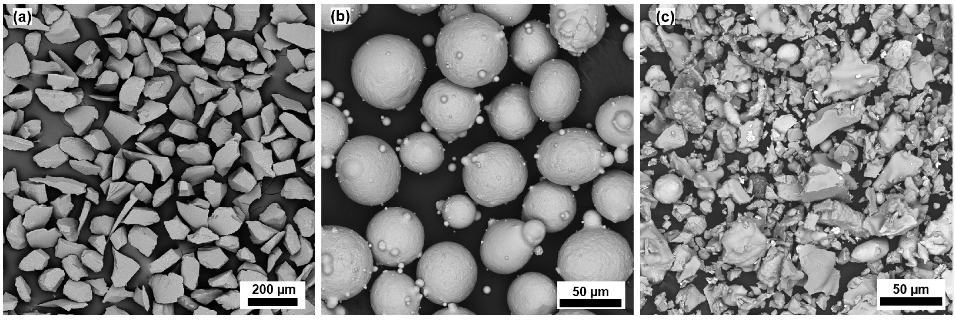
2.1. Synthesis and Coatings Deposition

The SiC-NiCrAlY cermet was synthesized in a planetary ball mill (PQ-N2, Across International), using a ball and material weight ratio of 20:1 at 300 rpm. First, industrial-grade SiC of a 180 mesh grain size (Figure 1a) was milled for 4 h; then, 3 wt.% of ZrB2 nanoparticles (80–100 nm Nanoshell) was added to stabilize the SiC during thermal spraying [23] and milled for 2 more hours. This mixture was added to NiCrAlY metallic powders (Oerlikon Metco (Figure 1b), with a relation of 21:79 wt.%, respectively, by milling for 8 h. Finally, additional SiC (32 wt.%) was added to the resulting SiC-NiCrAlY cermet to increase the carbide content. This carbide was ground for approximately 1.5 h to avoid the production of a finer powder, followed by a superficial chemical treatment at 400 °C for 30 min with Triethoxy(ethyl)silane (Sigma Aldrich) to stabilize the SiC [24,25], in order to reduce its decomposition during the spraying process. The low density of the final powder generated in the laboratory detrimentally affects its fluidity, making it difficult to feed it during the spraying process. This difficulty was resolved by adding commercial Cr3C2-NiCr (Amdry) powder (Figure 1c) in a proportion of 30:70 wt.%, respectively. These final conditions were defined after a series of preliminary tests to reach a minimum hardness of ~690 HV on the coating.
Incoloy 330 was used as a substrate for coating deposition. The surface to be coated was conditioned by grit-blasting up to Ra ≈ 7.2 μm and acetone cleaned. The Cr3C2-NiCr (C1) and SiC-NiCrAlY/Cr3C2-NiCr (C2) coatings (Figure 2) were fabricated at the SURESA company facilities with the HVOF (XPOJET 5000) spraying process; the spraying parameters are shown in Table 1. The coatings’ thicknesses were approximately 350 µm for C1 and 162 µm for C2. The difficulties associated with the fluidity of the C2 powder affected its feeding during the spraying process, making it difficult to grow past 150 microns. Once the coatings were fabricated, the specimens were heat-treated in an oven at 560 °C for 8 h to induce chromium carbide precipitation, increasing the hardness of both coatings [26]. Finally, the plates were sectioned by a water jet into 25 × 25 mm and 40 × 25 mm samples.

2.2. Coatings’ Characterization

Cross-sections of coatings C1 and C2 were prepared metallographically. The microstructure was examined using a scanning electron microscope (SEM, TESCAN MIRA 3 LMU). Phase identification of the powders and coatings was analyzed by the X-ray diffraction technique (XRD, PANalytical Empyrean diffractometer) using a CuKα radiation source at an acceleration potential of 45 kV, a diffraction angle 2θ range between 20° and 100°, and a step of 0.02°.
The microhardness of the specimens was measured by Vickers indentation, in a cross-section, using a Future Tech FM-800 microhardness tester, a load of 500 g, 15 s dwell time, and a series of 10 indentations. The fracture toughness (KIC) was evaluated by the indentation method using the same micro-hardness tester, by making a series of 7 indentations to obtain a statistic of this value. The KIC was calculated with the Palmqvist equation [27]
K l c = 0.0319 P a l a
where P is the load, a is half of the length of the indentation mark, and la is the length of lateral cracks (Palmqvist cracks) plus a. The applied loads were 1000 g for C1 and 300 g for C2 to generate cracks on the edge of the indentation. Images of the cracks and indentation marks were captured by SEM to take their measurements.

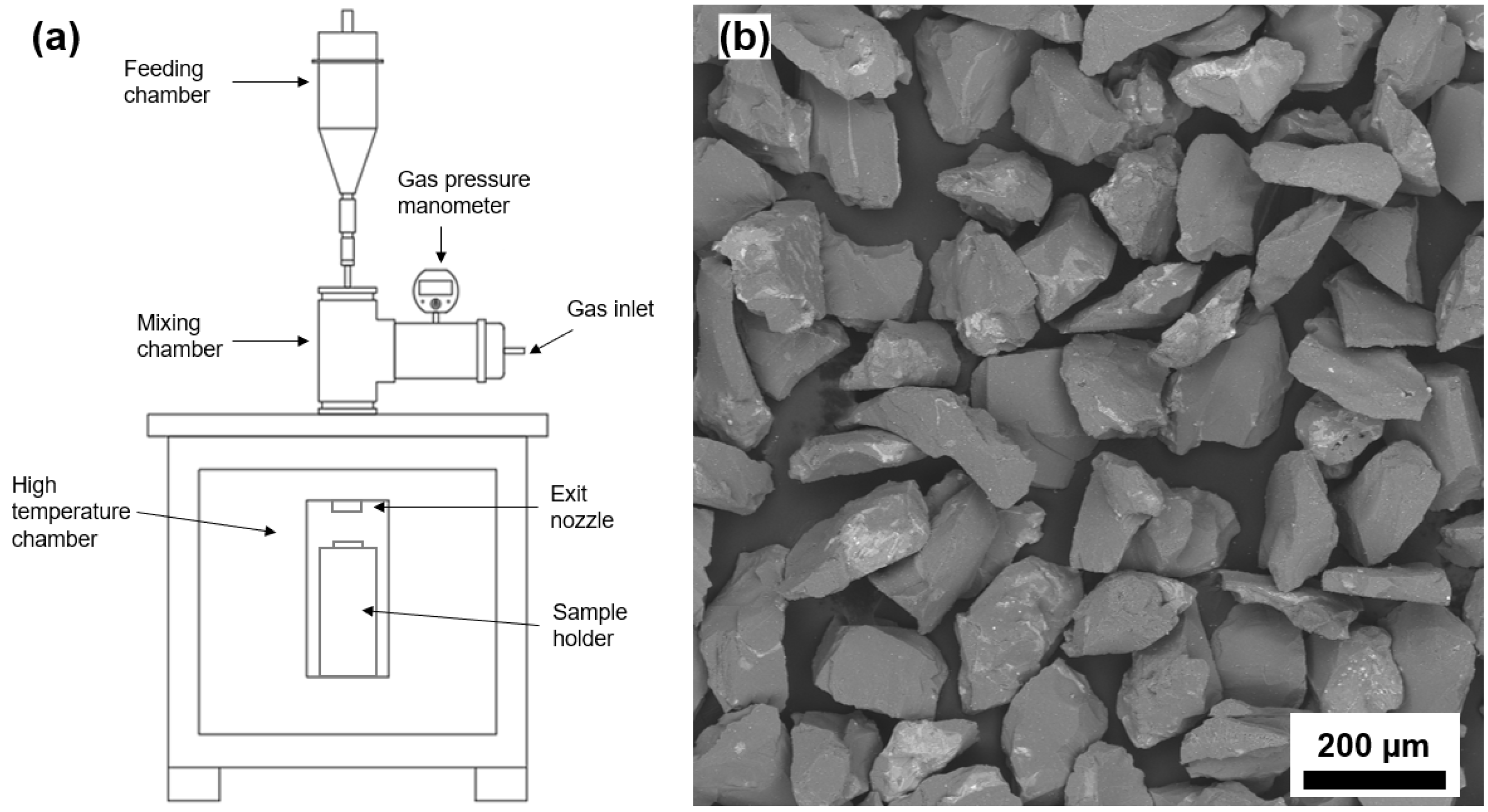
2.3. High-Temperature Erosion Wear Test

The erosion test at both temperatures (900 °C and room temperature (RT)) were carried out in a sand-blast type erosion test machine (Figure 3a). Semi-angular alumina (Figure 3b) of 125–150 µm, sieved, was used as erodent. Drag air with a dew point of −45 °C was used as the carrier fluid and accelerated through a 1.5875 mm diameter outlet nozzle. The erosion parameters are listed in Table 2. Particle velocity was measured by the double-disc method. Surface specimens were prepared to obtain a roughness ≤ 1 µm, according to ASTM G76 [1], and ultrasonically cleaned in an acetone bath for 10 min before and after the erosion. The mass loss was measured using a 0.01 mg precision analytical balance (Sartorius ATILON). Each condition was repeated twice to confirm the result, performing a third test if the difference between the values was greater than 8% [28]. The volumetric erosion rate was calculated by [29,30]:
E = v o l u m e   o f   r e m o v e d   m a t e r i a l   m a s s   o f   e r o s i v e   p a r t i c l e s   s t r i k i n g   t h e   s u r f a c e  
The maximum penetration of wear marks was measured using contact profilometry (Veeco DEKTAK 150 SURFACE PROFILER). Moreover, eroded surfaces and cross-sections were analyzed with the SEM to characterize the erosion mechanisms (damage generated).

3. Results and Discussion

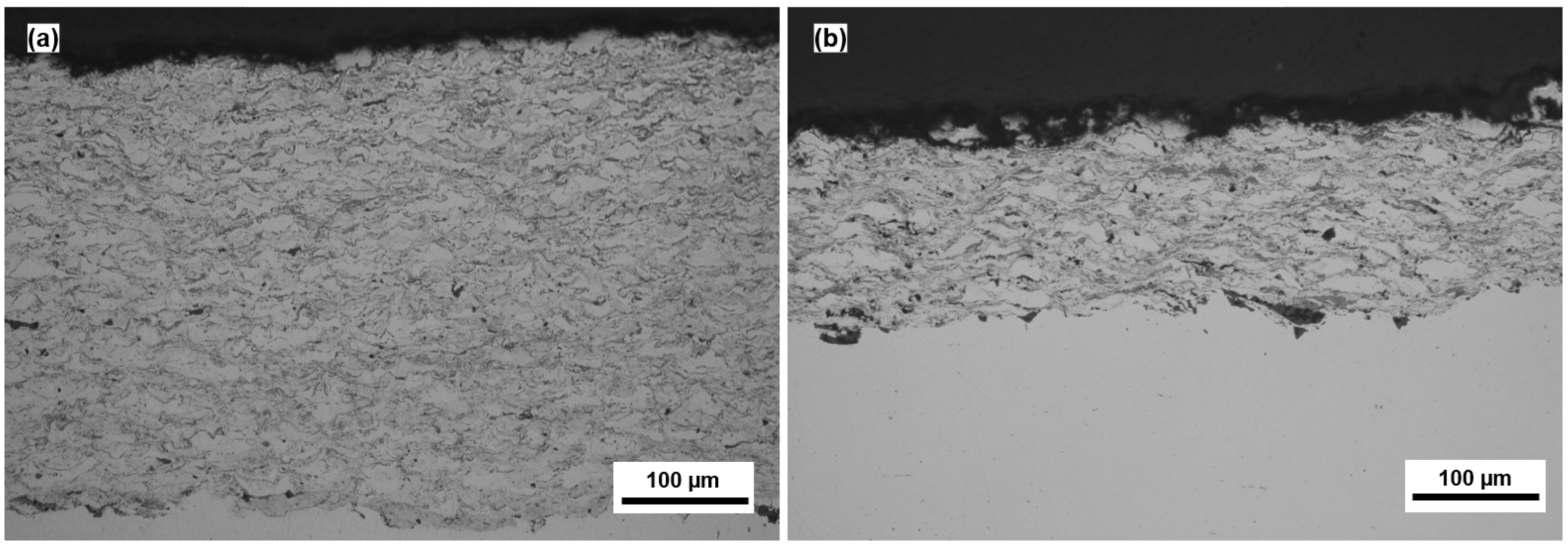
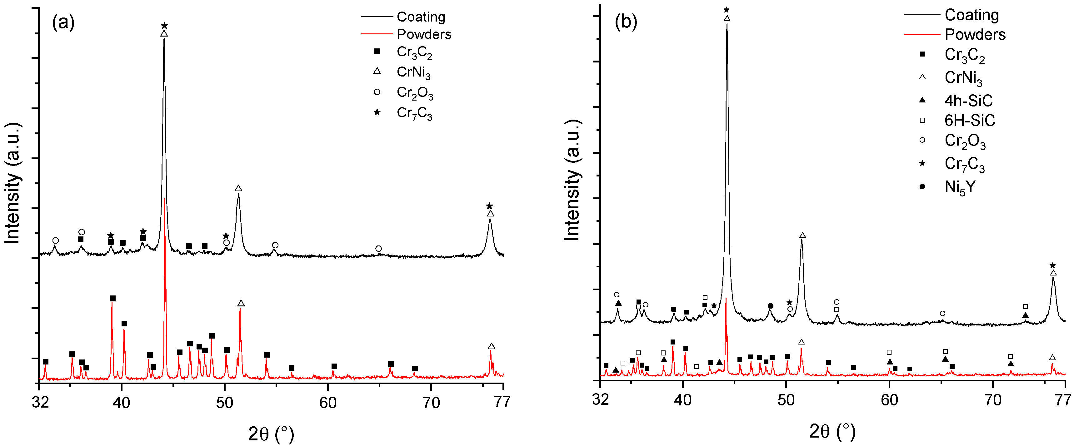
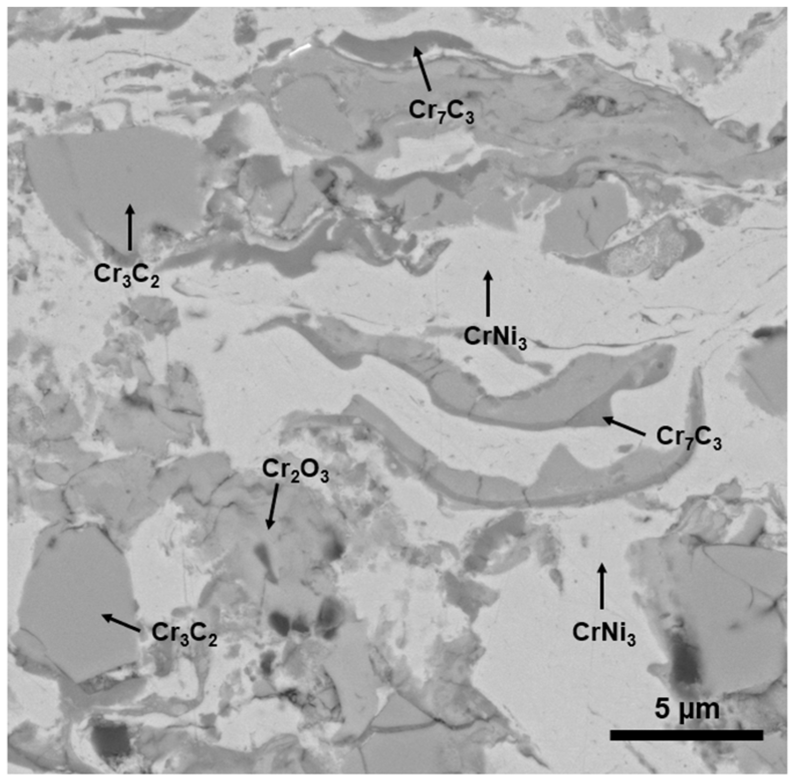
3.1. Coating Characterization
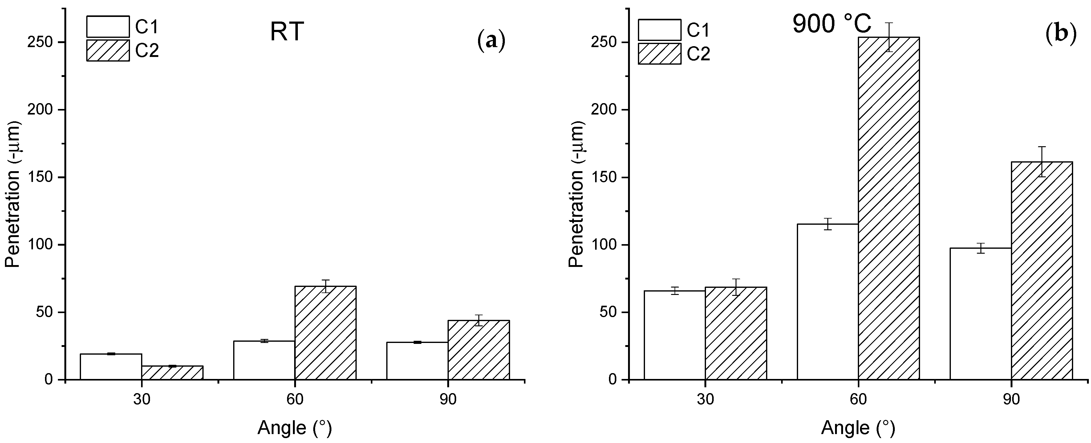
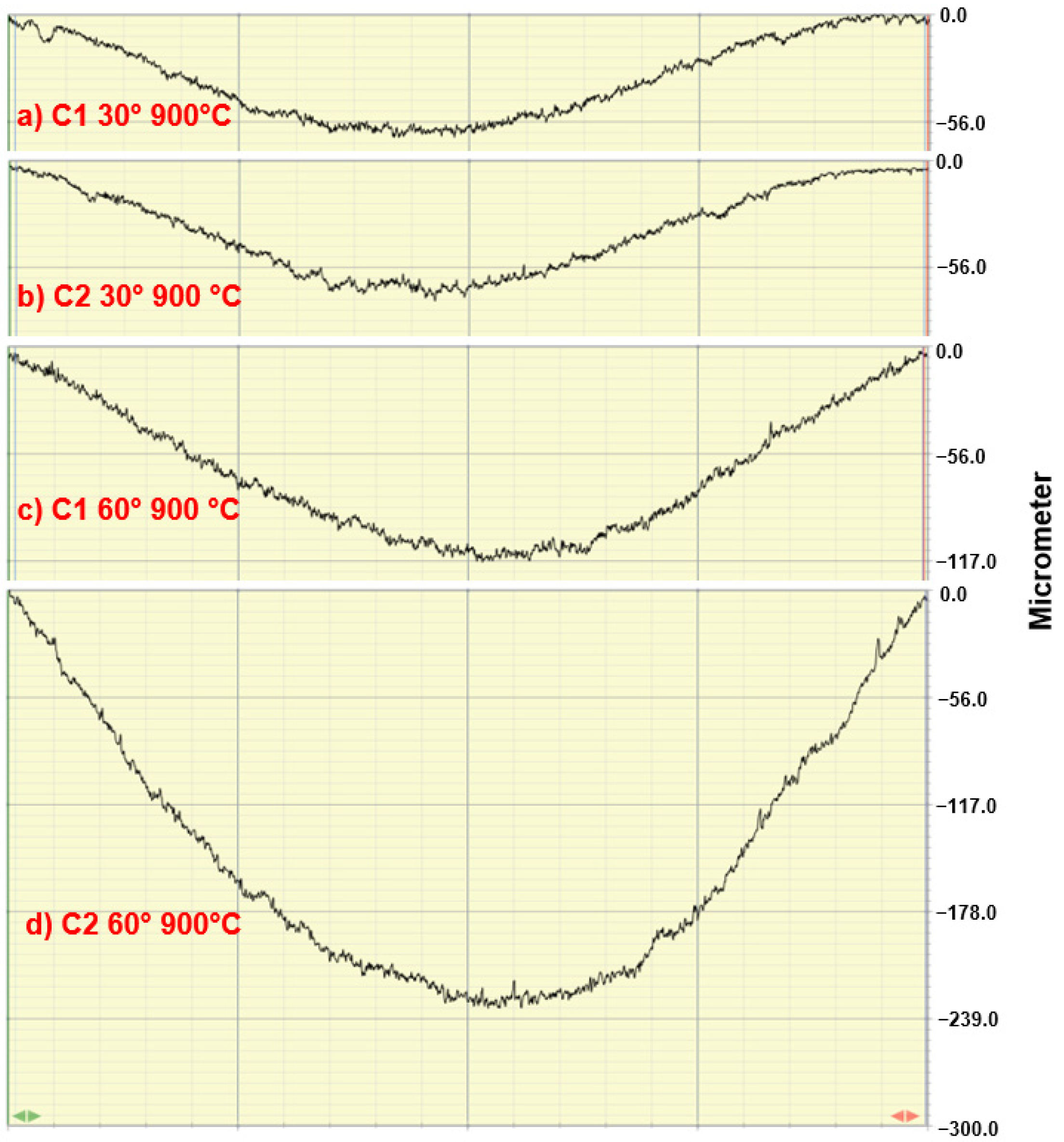
The diffraction patterns of the C1 coating and powders are shown in Figure 4a. CrNi3 peaks are observed in both conditions; the coating pattern shows secondary Cr3C2 peaks with less intensity, and some disappear (not detected) compared with the powder pattern. This phenomenon is due to the decarburization of Cr3C2 and the Cr oxidation processes that the material experiences during the spraying process (formation of Cr7C3 and Cr2O3, respectively) [31,32,33,34,35,36,37]. Due to the high content of Cr3C2-NiCr (70 wt.%) the C2 material contains, the diffraction patterns of both powders and coating (Figure 4b) are similar to those observed for the C1 material, only showing additional peaks corresponding to SiC phases and Ni5Y related to NiCrAlY [38]. The absence of SiO suggests that the SiC maintains its stability during the spraying process. Additional peaks related to the NiCrAlY were not identified due to a possible overlap with the CrNi3 peaks.
The cross-section of C1 (Figure 5) shows the typical microstructure generated with the HVOF process consisting of a dense Cr3C2-NiCr splat-like structure (chromium carbides distribution in the nickel–chromium (CrNi3) matrix). The porosity percentage was less than 1%, as is expected for this type of coating [33,35,36].
The C2 coating (Figure 6a) has a more complex microstructure than C1. It contains two metallic phases (NiCr and NiCrAlY) that are indistinguishable from one another using backscattered electrons because Ni is the principal element. The darker particles observed are associated with the SiC. The rest of the splat-like Cr3C2-NiCr structure and the porosity (less than 1%) are similar [33,34]. An EDS elemental mapping analysis (Figure 6b) revealed the distribution of the phases mentioned above. In this image, it is possible to identify the NiCrAlY because of the presence of aluminum. The oxygen-rich areas are associated with decarburized and oxidized Cr3C2 splats.
The microhardness and fracture toughness by the indentation method are shown in Table 3. The results show that C2 is 11% harder than C1. This increase was attributed to the cermet prepared in the laboratory (SiC/NiCrAlY) and its presence in the final coating [16,17,18]. The C1 fracture toughness had a superior value of 62.2% greater than C2. This can be related to better inter-splat cohesion and the lower hardness value of this coating compared to C2. Moreover, comparing the KIC of C1 with those values reported in the literature (2.1 to 4.2 MPa m1/2), it is noticed (Table 3) that the C1 coating displayed better fracture toughness, since it had greater hardness values (from 825 to 1050 HV) and therefore more brittleness [6,31,35,39]. The low fracture toughness of the C2 coating can be attributed to poor inter-splat cohesion, promoted by the silicon carbide grains. When seeking to stabilize these particles during the thermal spraying process, they did not soften enough to achieve good cohesion with the other phases, and as a result, generated areas that facilitated the propagation of cracks. Figure 7 shows an indentation mark and the crack length for the KIC measurement, in which can be observed the inter-splat crack propagation.

3.2. Erosion Tests

The erosion rate graphs of all the studied conditions are shown in Figure 8. From Figure 8a, it can be observed that at 25° C (RT), the erosion of C1 has a brittle tendency, with maximum wear at 60°. Similar results were reported by Z. Li et al. and X. Zhang et al., where their Cr3C2-NiCr coatings achieved maximum erosion at middle impact angles (60° or 70°) [40,41]. M.A. González et al. [42] and H. Zhang et al. [43] reported in cermet-type materials that this ductile-brittle behavior of the Cr3C2-NiCr coating could be attributed to the preferential erosion of the binder phase (NiCr). The continuous impact of particles induces considerable plastic deformation and embrittlement of the binder, promoting its detachment by cracking; then, the exposed Cr3C2 particles fracture rapidly due to their subsequent impact. On the other hand, C2 showed a completely brittle behavior (maximum erosion rate at 90°). At 30°, these two coatings have no notable difference in their erosion rate, but at medium (60°) and normal (90°) impact angles, the erosion rate of C2 samples increases, experiencing maximum wear at normal impact angles. These C1 and C2 behaviors can be explained in terms of their hardness and toughness properties and the impact angle. At a low impact angle, the normal load component of the impact is low. Both coatings’ metallurgical condition (hardness) is such to impart good erosion resistance (a somewhat lower erosion rate is observed for the harder cermet, C2). As the impact angle increases, so does the component of the normal load. The impact load effect reaches deeper splats, not just the superficial ones. In this sense, it is important to consider the effect of the KIC, as was presented earlier. C2 possesses lower values, which is assumed to affect its erosion resistance under medium or high impact angles (medium or high normal load). On the other hand, C1 displayed higher KIC, which means that under repetitive particle hitting (cyclic load) C1 will possess better erosion resistance.
As was expected (Figure 8b), at 900 °C, the erosion rate of both systems increases for all impact angles compared to room temperature, e.g., an increment of 83.8% for C1 and 118.4% for C2 at the impact angle of 30°. The erosion behavior of C1 showed a constant erosion rate at the three impact angles (3 % biggest difference) and presented better erosion resistance than C2 in all test conditions. This behavior could be explained by the increment of ductility that the materials experience at this temperature, inducing major material removal at low erosion angles (increasing the ductile erosion behavior) [44]. This change in erosion tendency is more notorious for the C2 material, shifting its maximum erosion rate from 90° at RT to 60° at 900 °C, also by comparing the erosion rate difference between 30° and 90° at room temperature (84.2%—brittle tendency) and 900 °C (23.7%—brittle tendency reduced considerably).
It is worth mentioning that in many applications, the remaining life of a component is determined by its thickness loss and not by the volumetric loss, so it is important to analyze the erosion penetration in the material. Figure 9 shows the maximum penetration profiles obtained by profilometry from both specimens. Let us take the case of C1 at 900 °C with impact angles of 30° and 60°; the difference in erosion rate was only 2.8. %, while the penetration difference was 75% (see Figure 10a,c). In both cases, the lower penetration occurred at 30°; this is because the tilt of the sample created a greater erosion area, and their hardness reduced the penetration on the coatings.
A similar example is the comparison of C2 at 900 °C, 30°, and 60°. Its volumetric erosion difference is 28.8%; meanwhile, the penetration difference between them is 231.3% (Figure 10b,d). At 30° RT, C2 shows less penetration than C1, which can be attributed to the fact that harder materials have better erosion penetration resistance at low impact angles. It was observed that the highest penetration was always at a 60° impact angle in all cases, reaching full penetration in the C2 at 900 °C and even eroding the substrate; this can be attributed to the combination of low and normal angle erosion mechanisms resulting in more material removal, as is shown in the next section. The erosion of C2 at 900 °C and 60° was the only case where the substrate was eroded. Therefore, an approximation to determinate the volume percentage of the eroded substrate was made using profilometry results, showing that this represented less than 7% of the total eroded volume.

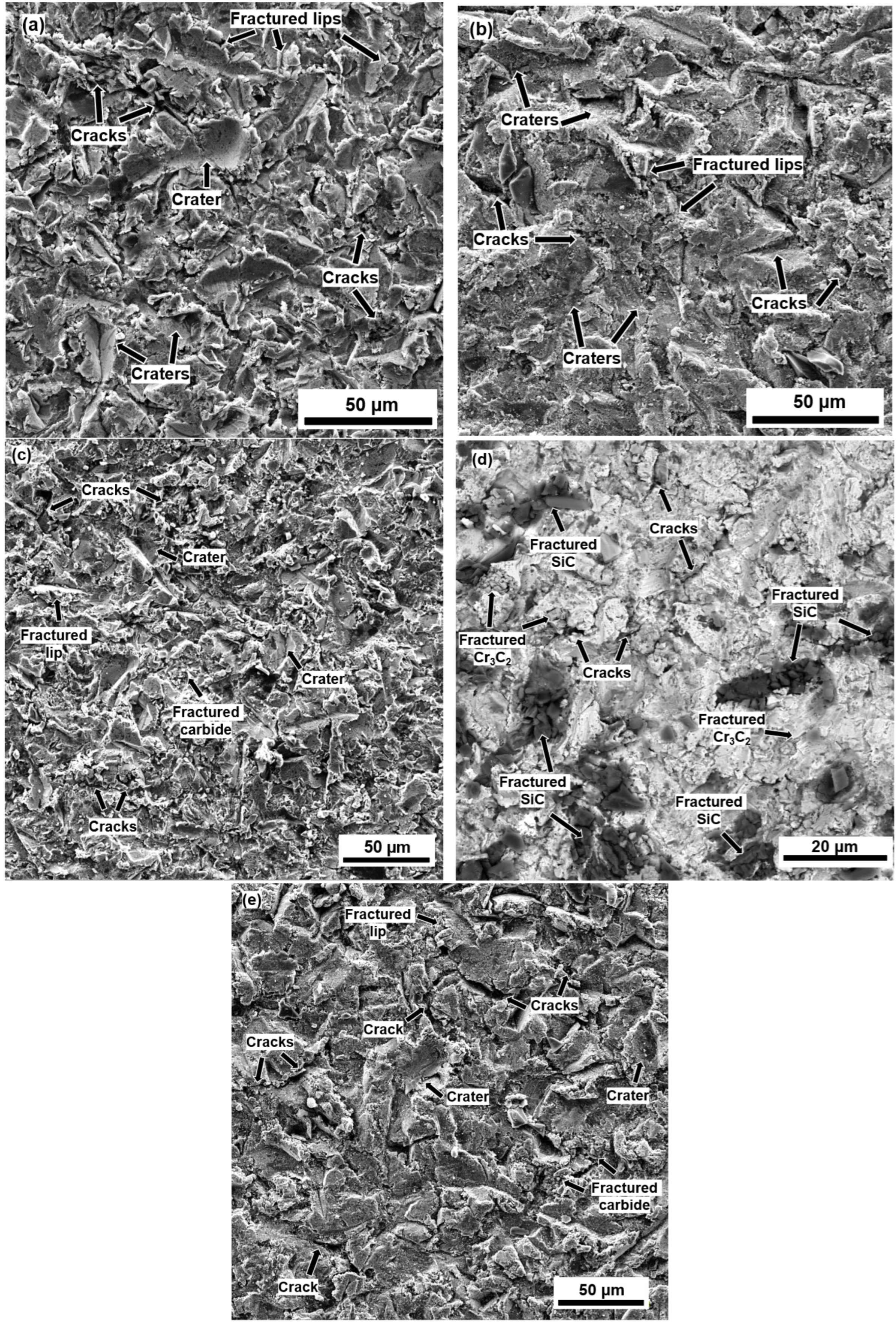
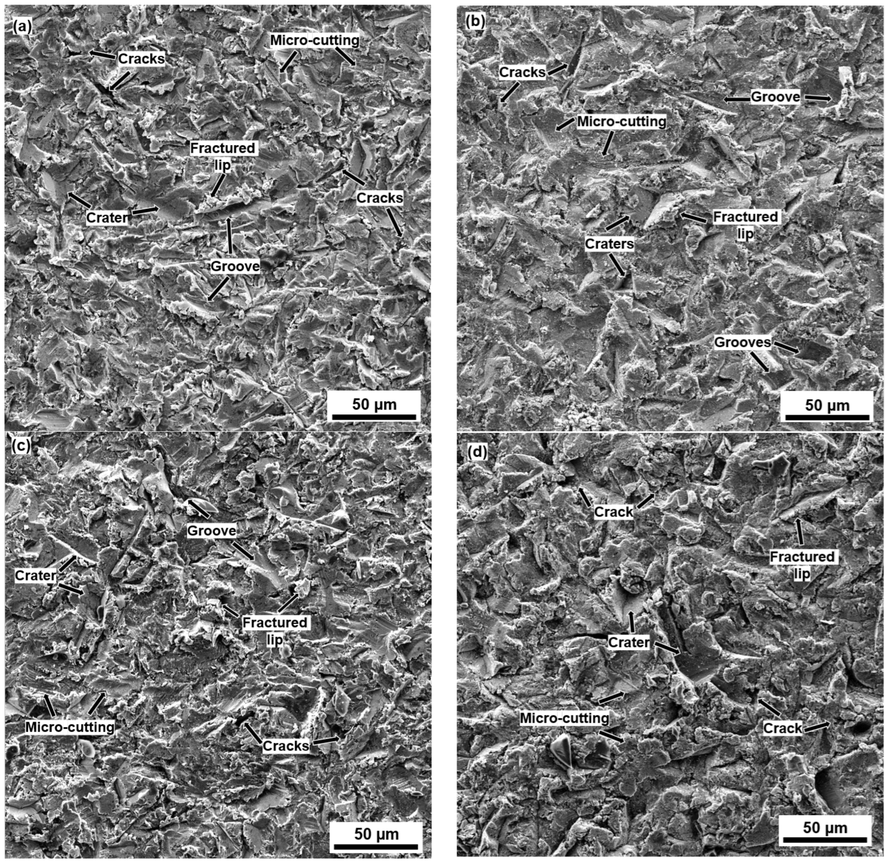
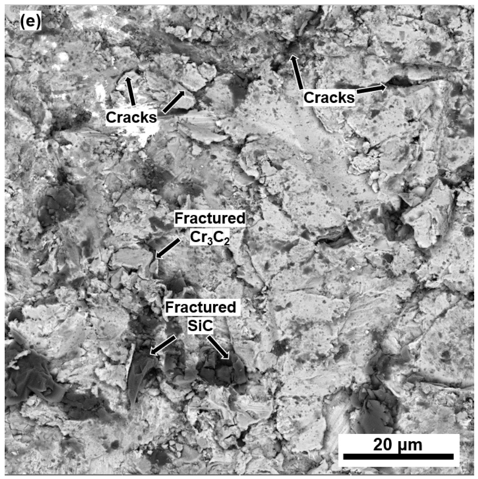
3.3. Erosion Mechanisms

The C1 and C2 samples at both RT and 900 °C showed the same erosion ductile mechanisms (craters, micro-cutting, grooves, and lips formation). Still, they increased in size at 900 °C for both coatings and all impact angles.
The erosion mechanisms presented in C1 and C2 specimens at RT and 30° (Figure 11a,b,d) were mainly by micro-cutting and in minor presence grooves, frontal, and lateral lips (associated with plastic deformation). In these same figures, cracking is observed in some lips, indicating that during the erosion test, they were susceptible to being fractured by the continuous impact of erodent particles, generating detached chips. As mentioned earlier, the appearance (smaller erosion damage features) of this type of erosion mechanism in the C2 coating is attributed to its higher hardness. Also identified were fractured chromium carbide and silicon carbide grains (Figure 11e). At 900 °C (Figure 11c,f), there were no observed fractured carbides in C1, while in C2 the fractured carbides were less abundant but still present. These phenomena were attributed to the matrix’s ductility (softening) increment, which explains the high erosion rate difference between RT and 900 °C (increment of 83.8% in C1 and 118.4% in C2) [2,44].
In the case of the C1 and C2 coatings eroded at RT at a 90° impact angle (Figure 12a,c), the brittle fracture was the principal mechanism. Evidence of this was the presence of cracked and fractured lips and carbides (a large number of micro-cracks along almost the total eroded surface of the C2 coating sample (Figure 12d)). The deformation features (craters shape) attributed to the plastic damage mechanisms were irregular due to the angular particles hitting at a normal impact and forming lips at their edge; this observation was more notorious in C1. At 900 °C (Figure 12b,e), the brittle mechanisms were still present, especially in C2; this is assumed to be possible because SiC particles are hard but brittle, even under high-temperature conditions.
The C1 and C2 eroded surface at RT and at an impact angle of 60° (Figure 13) showed a combination of erosion mechanisms commonly observed under normal and oblique impact angles. Plastic deformation and brittle fractures are commonly observed on these cermets constituted by ductile and brittle phases. There were craters, grooves, lips in the edges of the grooves and the craters, and micro-cutting (Figure 13a,c). Brittle mechanisms, such as fractured carbides and some cracks, were observed. The main difference was found on the C2 specimens, where more fractured carbides were observed (Figure 13e). Then, the presence of a second brittle phase (SiC particles) in these samples explains the large volume loss value compared to the C1 specimen. At 900 °C (Figure 13b,d), the presence of a second soft phase (splats of NiCrAlY) affected the C2 sample’s ductility (softening) to a greater extent. Both factors induced this coating to experience the greatest erosion rate and penetration.
Cross-sections of eroded C1 and C2 at the 900 °C and 90° impact angle samples were selected to analyze the erosion damage. The C2 sample (Figure 14a) showed considerable inter-splat cracking and splat detachment (fractured). It is observed that the SiC particles are preferential sites for inter-spalt crack propagation (Figure 14a,b). Trans-splat fracture is also observed in this coating (Figure 14c). Contrarily, the eroded C1 sample showed less damage in terms of fracture and cracking propagation (Figure 14d). The above confirms the better performance of the C1 coating subjected to the erosion conditions of this investigation.

4. Conclusions

  • The SiC added to the C2 specimen was successfully stabilized, increasing the microhardness by 11% compared with the C1 coating but decreasing its KIC by 62.2%.
  • The better erosion resistance of C1 was attributed to its higher KIC.
  • The addition of SiC particles combined with their low KIC promoted the nucleation and propagation of inter-splat cracking, detrimentally affecting their erosion resistance at both temperatures.
  • At 900 °C, the erosion rate of both coatings increased, and the ductile behavior of both coatings also increased due to the increment in the metallic matrix ductility.
  • The maximum penetration depth always occurred at a 60° impact angle due to a combination of low-impact-angle erosion mechanisms (micro-cutting and grooves), and normal-impact-angle erosion mechanisms (craters and cracks formation).

Author Contributions

Conceptualization, E.E.V.B. and M.A.G.A.; methodology, E.E.V.B., E.R.d.A. and M.A.G.A.; validation, E.E.V.B., J.C.D.G. and E.R; formal analysis, E.E.V.B., E.R.d.A. and M.A.G.A.; investigation, E.E.V.B.; resources, E.R.d.A., J.C.D.G. and M.A.G.A.; data curation, E.E.V.B., G.I.V.G. and J.M.C.A.; writing—original draft preparation, E.E.V.B.; writing—review and editing, E.R.d.A., J.d.J.I.M. and M.A.G.A.; visualization, E.E.V.B. and G.I.V.G.; supervision, E.R.d.A.; project administration, E.E.V.B. and M.A.G.A.; funding acquisition, E.R.d.A., J.d.J.I.M. and J.M.C.A. All authors have read and agreed to the published version of the manuscript.

Funding

This research received no external funding.

Institutional Review Board Statement

Not applicable.

Informed Consent Statement

Not applicable.

Data Availability Statement

The data that support the findings of this study are available from the corresponding author upon reasonable request.

Acknowledgments

The authors would like to thank to the CONACyT for the scholarship conferred to the Ph student E.E.V. with number: 856693. Additionally, they wish to thank the Universidad de Guadalajara, SURESA, and COMIMSA for their technical support and cooperation.

Conflicts of Interest

The authors declare no conflict of interest.

References

  1. ASTM G76-18; Standard Test Method for Conducting Erosion Tests by Solid Particle Impingement Using Gas Jets. ASTM International: West Conshohocken, PA, USA, 2018; pp. 1–6.
  2. Kumar, P.; Sidhu, B.S. Characterization and High-Temperature Erosion Behaviour of HVOF Thermal Spray Cermet Coatings. J. Mater. Eng. Perform. 2016, 25, 250–258. [Google Scholar] [CrossRef]
  3. Yang, J.Z.; Fang, M.H.; Huang, Z.H.; Hu, X.Z.; Liu, Y.G.; Sun, H.R.; Huang, J.T.; Li, X.C. Solid Particle Impact Erosion of Alumina-Based Refractories at Elevated Temperatures. J. Eur. Ceram. Soc. 2012, 32, 283–289. [Google Scholar] [CrossRef]
  4. Surzhenkov, A.; Antonov, M.; Goljandin, D.; Kulu, P.; Viljus, M.; Traksmaa, R.; Mere, A. High-Temperature Erosion of Fe-Based Coatings Reinforced with Cermet Particles. Surf. Eng. 2016, 32, 624–630. [Google Scholar] [CrossRef]
  5. Berger, L.M. Application of Hardmetals as Thermal Spray Coatings. Int. J. Refract. Met. Hard Mater. 2015, 49, 350–364. [Google Scholar] [CrossRef]
  6. Murthy, J.K.N.; Satya Prasad, K.; Gopinath, K.; Venkataraman, B. Characterisation of HVOF Sprayed Cr3C2-50(Ni20Cr) Coating and the Influence of Binder Properties on Solid Particle Erosion Behaviour. Surf. Coat. Technol. 2010, 204, 3975–3985. [Google Scholar] [CrossRef]
  7. Matthews, S.; James, B.; Hyland, M. High Temperature Erosion of Cr3C2-NiCr Thermal Spray Coatings-The Role of Phase Microstructure. Surf. Coat. Technol. 2009, 203, 1144–1153. [Google Scholar] [CrossRef]
  8. Mishra, S.B.; Chandra, K.; Prakash, S. Characterisation and Erosion Behaviour of NiCrAlY Coating Produced by Plasma Spray Method on Two Different Ni-Based Superalloys. Mater. Lett. 2008, 62, 1999–2002. [Google Scholar] [CrossRef]
  9. Wang, Y.; Sun, C.; Sun, J.; Zhao, W.; Dong, L.; Li, L.; Meng, F. Erosion Behavior of Arc Sprayed FeTi/CrB MMC Coating at Elevated Temperature. Surf. Coat. Technol. 2015, 262, 141–147. [Google Scholar] [CrossRef]
  10. Kulu, P.; Hussainova, I.; Veinthal, R. Solid Particle Erosion of Thermal Sprayed Coatings. In Proceedings of the Wear; Elsevier: Amsterdam, The Netherlands, 2005; Volume 258, pp. 488–496. [Google Scholar]
  11. Raghavendra Naik, K.; Kumar, R.K.; Saravanan, V.; Seetharamu, S.; Sampathkumaran, P. The Study of Cr3C2-25NiCr and 35WC-Co/65NiCrBSi-Based HVOF Coatings for High-Temperature Erosion Resistance Application. Tribol.-Mater. Surfaces Interfaces 2021, 16, 10–22. [Google Scholar] [CrossRef]
  12. Luo, L.M.; Liu, S.G.; Yu, J.; Luo, J.; Li, J. Effect of Al Content on High Temperature Erosion Properties of Arc-Sprayed FeMnCrAl/Cr3C2 Coatings. Trans. Nonferrous Met. Soc. China (Engl. Ed.) 2010, 20, 201–206. [Google Scholar] [CrossRef]
  13. Nicholls, J.R. Designing Oxidation-Resistant Coatings. JOM 2000, 52, 28–35. [Google Scholar] [CrossRef]
  14. Mori, T.; Kuroda, S.; Murakami, H.; Katanoda, H.; Sakamoto, Y.; Newman, S. Effects of Initial Oxidation on β Phase Depletion and Oxidation of CoNiCrAlY Bond Coatings Fabricated by Warm Spray and HVOF Processes. Surf. Coat. Technol. 2013, 221, 59–69. [Google Scholar] [CrossRef]
  15. Ajdelsztajn, L.; Tang, F.; Kim, G.E.; Provenzano, V.; Schoenung, J.M. Synthesis and Oxidation Behavior of Nanocrystalline MCrAIY Bond Coatings. J. Therm. Spray Technol. 2005, 14, 23–30. [Google Scholar] [CrossRef]
  16. Zhao, L.; Parco, M.; Lugscheider, E. Wear Behaviour of Al2O3 Dispersion Strengthened MCrAlY Coating. Surf. Coat. Technol. 2004, 184, 298–306. [Google Scholar] [CrossRef]
  17. Mathapati, M.; Ramesh, M.R.; Doddamani, M. High Temperature Erosion Behavior of Plasma Sprayed NiCrAlY/WC-Co/Cenosphere Coating. Surf. Coat. Technol. 2017, 325, 98–106. [Google Scholar] [CrossRef]
  18. Nithin, H.S.; Desai, V.; Ramesh, M.R. Elevated Temperature Solid Particle Erosion Behaviour of Carbide Reinforced CoCrAlY Composite Coatings. Mater. Res. Express 2018, 5, 066529. [Google Scholar] [CrossRef]
  19. Wielage, B.; Wilden, J.; Schinck, T.; Wank, A. Development of SiC-Composite Feedstock for HVOF Applications. In Proceedings of the International Thermal Spray Conference, Essen, Germany, 4–6 March 2002; pp. 790–795. [Google Scholar] [CrossRef]
  20. Rincón, A.; Pala, Z.; Hussain, T. A Suspension High Velocity Oxy-Fuel Thermal Spray Manufacturing Route for Silicon Carbide–YAG Composite Coatings. Mater. Lett. 2020, 281, 128601. [Google Scholar] [CrossRef]
  21. Arrabal, R.; Pardo, A.; Merino, M.C.; Mohedano, M.; Casajús, P.; Merino, S. Al/SiC Thermal Spray Coatings for Corrosion Protection of Mg–Al Alloys in Humid and Saline Environments. Surf. Coat. Technol. 2010, 204, 2767–2774. [Google Scholar] [CrossRef]
  22. Mubarok, F.; Armada, S.; Fagoaga, I.; Espallargas, N. Thermally Sprayed SiC Coatings for Offshore Wind Turbine Bearing Applications. J. Therm. Spray Technol. 2013, 22, 1303–1309. [Google Scholar] [CrossRef]
  23. Tului, M.; Giambi, B.; Lionetti, S.; Pulci, G.; Sarasini, F.; Valente, T. Silicon Carbide Based Plasma Sprayed Coatings. Surf. Coat. Technol. 2012, 207, 182–189. [Google Scholar] [CrossRef]
  24. Meguro, K.; Ushida, T.; Hiraoka, T.; Esumi, K. Effects of Surfactants and Surface Treatment on Aqueous Dispersion of Silicon Carbide. Bull. Chem. Soc. Jpn. 1987, 60, 89–94. [Google Scholar] [CrossRef]
  25. Sawyer, L.C. Process for Dispersing Silicon Carbide Whiskers. U.S. Patent No. 4,956,316, 1990. Available online: https://patentscope.wipo.int/search/es/detail.jsf?docId=US37885526&_cid=P22-LFVGRB-57515-1 (accessed on 1 February 2023).
  26. Guilemany, J.M.; Miguel, J.M.; Vizcaíno, S.; Lorenzana, C.; Delgado, J.; Sánchez, J. Role of Heat Treatments in the Improvement of the Sliding Wear Properties of Cr3C2-NiCr Coatings. Surf. Coat. Technol. 2002, 157, 207–213. [Google Scholar] [CrossRef]
  27. Ponton, C.B.; Rawlings, R.D. Vickers Indentation Fracture Toughness Test Part 1 Review of Literature and Formulation of Standardised Indentation Toughness Equations. Mater. Sci. Technol. 1989, 5, 865–872. [Google Scholar] [CrossRef]
  28. Ibarra, J.; Rodríguez, E.; González, M.A.; Cuenca, S.L.; Medina, A.; Vásquez, G.I. Erosion Behavior of 440C Stainless Steel Cryogenically Treated. Rev. Mex. Ing. Química 2020, 19, 1255–1264. [Google Scholar] [CrossRef]
  29. Antonov, M.; Yung, D.L.; Goljandin, D.; Mikli, V.; Hussainova, I. Effect of Erodent Particle Impact Energy on Wear of Cemented Carbides. Wear 2017, 376–377, 507–515. [Google Scholar] [CrossRef]
  30. Sharma, S.K.; Venkata Manoj Kumar, B.; Kim, Y.W. Effect of Impingement Angle and WC Content on High Temperature Erosion Behavior of SiC-WC Composites. Int. J. Refract. Met. Hard Mater. 2017, 68, 166–171. [Google Scholar] [CrossRef]
  31. Xie, M.; Zhang, S.; Li, M. Comparative Investigation on HVOF Sprayed Carbide-Based Coatings. Appl. Surf. Sci. 2013, 273, 799–805. [Google Scholar] [CrossRef]
  32. Guilemany, J.M.; Nutting, J.; Llorca-Isern, N. Characterisation of Cr3C2–Nicr Cermet Powder for High Velocity Oxyfuel Spraying. Powder Metall. 1994, 37, 289–292. [Google Scholar] [CrossRef]
  33. Hussainova, I.; Antonov, M.; Jasiuk, I.; Du, X. Characterisation of Microstructure and Mechanical Properties of Cermets at Micro- and Nanoscales. Int. J. Mater. Prod. Technol. 2011, 40, 58. [Google Scholar] [CrossRef]
  34. Jonda, E.; Łatka, L.; Pakieła, W. Microstructure and Selected Properties of Cr3C2-Nicr Coatings Obtained by Hvof on Magnesium Alloy Substrates. Materials 2020, 13, 2775. [Google Scholar] [CrossRef]
  35. Vashishtha, N.; Sapate, S.G.; Jyoti Sahariah, B.; Bagde, P. Microstructural Characterization and Wear Behaviour of High Velocity Oxy-Fuel Sprayed Cr3C2-25NiCr Coating. Mater. Today Proc. 2018, 5, 17686–17693. [Google Scholar] [CrossRef]
  36. Zhou, W.; Zhou, K.; Li, Y.; Deng, C.; Zeng, K. High Temperature Wear Performance of HVOF-Sprayed Cr3C2-WC-NiCoCrMo and Cr3C2-NiCr Hardmetal Coatings. Appl. Surf. Sci. 2017, 416, 33–44. [Google Scholar] [CrossRef]
  37. Matthews, S. Development of High Carbide Dissolution/Low Carbon Loss Cr3C2-NiCr Coatings by Shrouded Plasma Spraying. Surf. Coat. Technol. 2014, 258, 886–900. [Google Scholar] [CrossRef]
  38. Bai, M.; Song, B.; Reddy, L.; Hussain, T. Preparation of MCrAlY–Al2O3 Composite Coatings with Enhanced Oxidation Resistance through a Novel Powder Manufacturing Process. J. Therm. Spray Technol. 2019, 28, 433–443. [Google Scholar] [CrossRef] [Green Version]
  39. Robertson, A.L.; White, K.W. Microscale Fracture Mechanisms of a Cr3C2-NiCr HVOF Coating. Mater. Sci. Eng. A 2017, 688, 62–69. [Google Scholar] [CrossRef]
  40. Li, Z.; Li, Y.; Li, J.; Li, F.; Lu, H.; Du, J.; Ran, X.; Zhang, X. Effect of NiCr Content on the Solid Particle Erosion Behavior of NiCr-Cr3C2 Coatings Deposited by Atmospheric Plasma Spraying. Surf. Coat. Technol. 2020, 381, 125144. [Google Scholar] [CrossRef]
  41. Zhang, X.; Li, F.; Li, Y.; Lu, Q.; Li, Z.; Lu, H.; Ran, X.; Qi, X. Comparison on Multi-Angle Erosion Behavior and Mechanism of Cr3C2-NiCr Coatings Sprayed by SPS and HVOF. Surf. Coat. Technol. 2020, 403, 126366. [Google Scholar] [CrossRef]
  42. González, M.A.; Rodríguez, E.; Mojardín, E.; Jiménez, O.; Guillen, H.; Ibarra, J. Study of the Erosive Wear Behaviour of Cryogenically and Tempered WC-CoCr Coating Deposited by HVOF. Wear 2017, 376–377, 595–607. [Google Scholar] [CrossRef]
  43. Zhang, H.; Dong, X.; Chen, S. Solid Particle Erosion-Wear Behaviour of Cr3C2–NiCr Coating on Ni-Based Superalloy. Adv. Mech. Eng. 2017, 9, 168781401769458. [Google Scholar] [CrossRef]
  44. Yang, G.J.; Li, C.J.; Zhang, S.J.; Li, C.X. High-Temperature Erosion of HVOF Sprayed Cr3C2-NiCr Coating and Mild Steel for Boiler Tubes. Proc. J. Therm. Spray Technol. 2008, 17, 782–787. [Google Scholar] [CrossRef]
Figure 1. Micrographs of (a) SiC particles, (b) NiCrAlY powder, and (c) Cr3C2-25NiCr powder.
Coatings 13 00720 g001
Figure 2. Cross-section of (a) C1 coating and (b) C2 coating.
Coatings 13 00720 g002
Figure 3. (a) High-temperature erosion test rig. (b) Alumina erodent particles.
Coatings 13 00720 g003
Figure 4. Diffraction patterns: (a) Cr3C2-NiCr and (b) SiC-NiCrAlY/Cr3C2-NiCr.
Coatings 13 00720 g004
Figure 5. Cr3C2-NiCr coating microstructure.
Coatings 13 00720 g005
Figure 6. SiC-NiCrAlY/Cr3C2-NiCr coating (a) microstructure and (b) EDS analysis.
Coatings 13 00720 g006aCoatings 13 00720 g006b
Figure 7. Indentation mark for KIC measurement in the C2 coating.
Coatings 13 00720 g007
Figure 8. Volumetric erosion rate plots (a) at room temperature and (b) at 900 °C.
Coatings 13 00720 g008
Figure 9. Average of erosion penetration plots (a) at room temperature and (b) at 900 °C.
Coatings 13 00720 g009
Figure 10. Profilometry plot of maximum penetration: (a) C1 30° 900 °C; (b) C1 60° 900 °C; (c) C1 30° RT; and (d) C2 60° 900 °C. (units in micrometers).
Coatings 13 00720 g010
Figure 11. Eroded surface 30° angle: (a) and (b) C1 at RT; (c) at 900 °C. (d) C2 at RT; (e) RT, backscattered electrons; and (f) at 900 °C.
Coatings 13 00720 g011
Figure 12. Eroded surface 90° angle: (a) C1 at RT and (b) at 900 °C. (c) C2 at RT; (d) RT, backscattered electrons; and (e) at 900 °C.
Coatings 13 00720 g012
Figure 13. Eroded surface 60° angle: (a) C1 at RT; (b) at 900 °C. (c) C2 at RT; (d) at 900 °C; and (e) RT, backscattered electrons.
Coatings 13 00720 g013aCoatings 13 00720 g013b
Figure 14. Cross section of eroded samples 90° at 900 °C. (ac) C2; (d) C1.
Coatings 13 00720 g014
Table 1. HVOF Spraying parameters.
Spraying ParametersC1C2
Oxygen flow707.92 L/min707.92 L/min
Kerosene flow333 mL/min333 mL/min
Spraying distance 38.1 cm38.1 cm
Feed rate8.8 RPM12.12 RPM
Argon flux3.78 L/min11.8 L/min
Table 2. Wear test parameters.
Parameters
ErodentAngular Alumina
Particle size125–150 µm
Feed rate14.6 g/min
Test time~40 min
Particle velocity46.8 m/s
Impact angle30°, 60°, 90°
Inner diameter of the outlet nozzle1.5875 mm
Erodent load500 g
Impact distance69.85 mm
Air pressure34.5 kPa
Test temperaturesRoom temperature (RT), 900 °C
Table 3. Mechanical properties of coatings.
CoatingMicrohardness (HV0.5)KIC (MPa m1/2)
C1641 ± 585.14 ± 0.27
C2711 ± 633.2 ± 0.47
Disclaimer/Publisher’s Note: The statements, opinions and data contained in all publications are solely those of the individual author(s) and contributor(s) and not of MDPI and/or the editor(s). MDPI and/or the editor(s) disclaim responsibility for any injury to people or property resulting from any ideas, methods, instructions or products referred to in the content.

