Article

Correlation of Tensile Properties of Arc-Sprayed Coatings and Easy Testing Methods

1
Laboratoire de Mécanique, Matériaux et Énergétique (L2ME), Faculté de Technologie, Université de Bejaia, Bejaia 06000, Algeria
2
Department of Chemical Engineering Materials Environment, Sapienza University of Rome, 00184 Roma, Italy
3
Academic Department of Mechanics, Universidade Tecnológica Federal do Paraná, Curitiba 81280-340, Brazil
*
Author to whom correspondence should be addressed.
Coatings 2023, 13(5), 878; https://doi.org/10.3390/coatings13050878
Submission received: 9 April 2023 / Revised: 27 April 2023 / Accepted: 5 May 2023 / Published: 7 May 2023
(This article belongs to the Special Issue Surface Engineering, Coatings and Tribology)

Abstract

:
Different techniques are usually employed to evaluate the mechanical properties of arc-sprayed coatings. In many situations, comparing properties is complex, and values extracted from tensile tests are required for structural projects. X6CrNi18-8 stainless steel and molybdenum were sprayed onto a mild steel substrate using the electric arc thermal spray technique to discuss this issue. After a detailed microstructure characterization, tensile tests were performed on both coatings to determine the yield strength and total elongation. Easy techniques were also applied: Vickers hardness and Charpy impact test. Tensile tests have shown that applying coatings increased the steel substrate’s total elongation. Molybdenum coating presented a higher impact resistance than the X6CrNi18-8 one, resulting in no correlation between elongation and Charpy values. On the other hand, correlations between hardness and yield strength were identified, opening a discussion on the effects of the microstructure and type of test used.

1. Introduction

Determining the mechanical properties of coatings is a relevant and complex task. This complexity is primarily associated with the possibility of assessing results affected by the properties of the substrate and its interface [1].
Thermally sprayed coatings are relatively thicker compared to other processes [2]. Because of the mechanical nature of anchoring the coating to the substrate [3], the adhesion strength is considered crucial, and it is standardized by ASTM; for example, by using tensile (C633-13) [4] or scratch (ASTM C1624-22) [5] devices.
Despite the importance of adhesion strength as a quality control of coating manufacturing, their applications for structural purposes should obey design requirements established by the same mechanical properties of bulk materials. Structural projects can be designed by strength (yield or ultimate tensile), toughness (total elongation), or both [6]. For these determinations, isolating the effects of the substrate and interface is not possible, and may not be helpful, considering that the system will operate as a unit in practice.
Building samples for tensile tests implies costs; performing this test takes longer than other methods. Hardness is usually made to evaluate strength [7] to surpass this issue, while impact test methods estimate the toughness of materials [8]. These accessible methodologies can save time and expenses, but interpreting results takes time.
Although expressing the strength of materials using hardness is a common task in engineering, the relationship depends on a series of conditions (e.g., indenter geometry and load) and different properties (e.g., elastic modulus, Poisson ratio, and strain hardening exponent). Pintaude [7] revised these aspects, showing that there are diverse approaches in the literature for brittle materials, meaning that a single value to convert hardness into strength has yet to exist.
The impact test is a practical methodology to check the brittleness of ductile metals. However, the specimen size is a variable that disturbs the interpretation of results. The fracture toughness depends on the plastic zone radius and the stress state to be considered an intrinsic material property. Li et al. [8] determined the plane fracture and impact toughness of 4340 steel under different metallurgical conditions. Relating each one to the tensile strength, they found a trade-off relationship between strength and fracture toughness. Conversely, an approximately invariable trend between strength and impact toughness could be described.
These issues should be considered for determining coatings’ strength. Tensile tests of coatings can be conducted using the same preparation of bulk materials, resulting in relationships between hardness and yield strength (constraint factor), for example. In the same way, the total elongation can be used as a toughness indicator, and the result obtained from the impact test used for a coating/substrate setup. Gärtner et al. [9] discussed cold-sprayed copper coatings’ hardness and strength relationships. They verified an excellent agreement with the bulk copper in comparatively soft states of deposited coatings. With increasing hardness, the yield strength increasingly deviates from the ideal correlation.
Within this perspective, this communication presents the results obtained for arc-sprayed metallic coatings tested under tensile tests, Vickers hardness, and Charpy impact test, checking possible correlations between properties and verifying the range of validity to use easy test methods to evaluate the strength and toughness of coatings.
This paper aims to check the possibility of evaluating a future application of arc-sprayed coatings in structural parts, such as crane components, which can be subject to wear, corrosion, or fatigue. However, their performances depend on similar or better mechanical properties than substrates. For these cases, correlating easy techniques with tensile tests is crucial for coating evaluation once each approach has particular issues.

2. Materials and Methods

2.1. Substrate and Raw Materials

Mild steel was used as a substrate, and its chemical composition as obtained using X-ray fluorescence analysis is shown in Table 1.
We deposited two types of coatings: X6CrNi18-8 stainless steel and Molybdenum (Mo), using wires as raw materials. These coatings were sprayed onto the surfaces of the samples using an electric arc gun. The chemical compositions of the input materials are shown in Table 2.

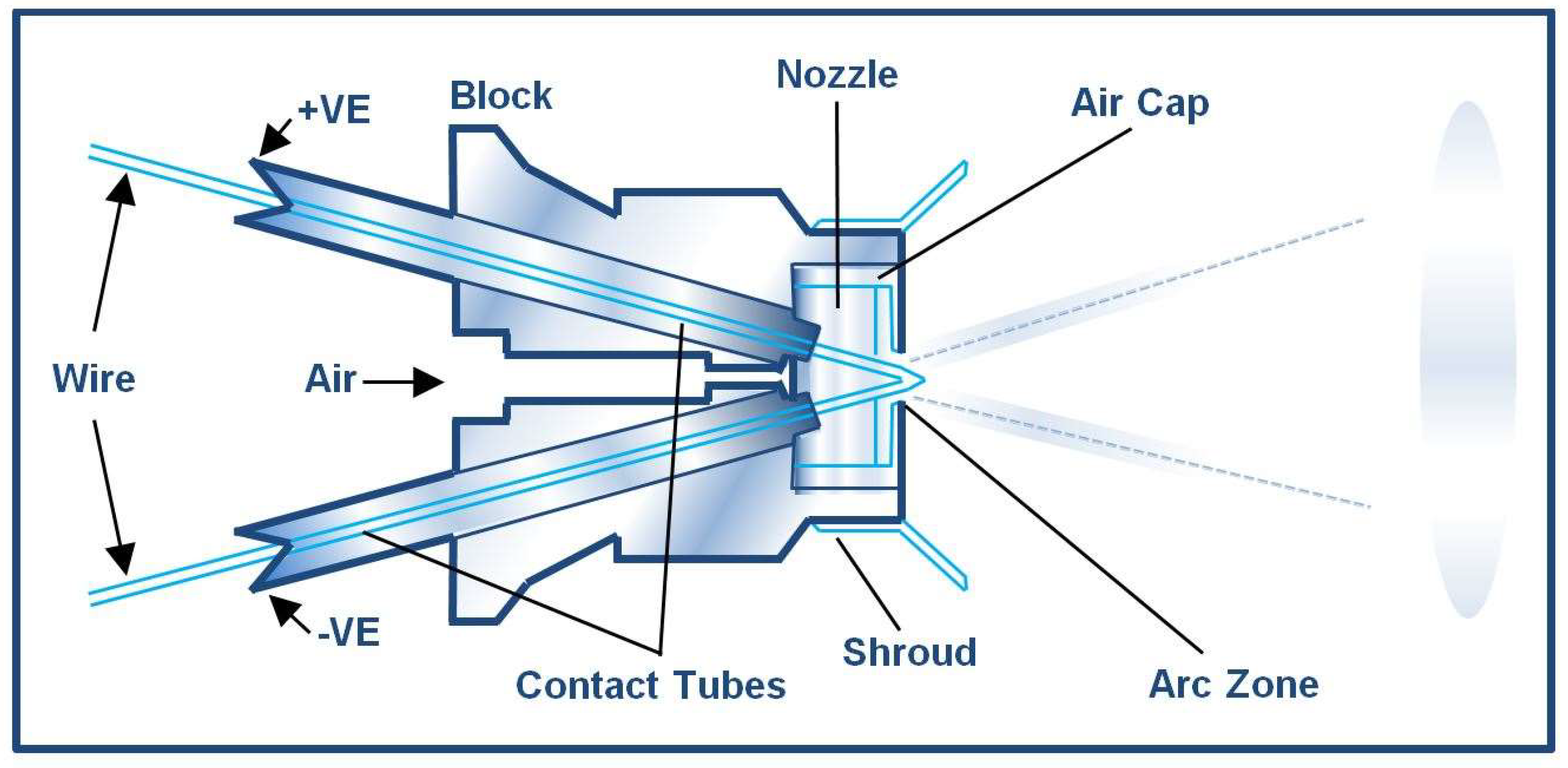
2.2. Spray Process and Parameters

The metal deposits were made using an arc spray 234 gun (Mettalisation LTD; Dudley, UK) using the electric arc as the energy source (Figure 1).
An electric arc is formed between two electrodes, continuously melting and breaking into droplets via a high-velocity jet of compressed air onto the substrate. The shot-blasted substrates were made to increase the surface roughness of the samples and improve the mechanical bond between the coating and substrate. The thickness of these coatings was approximately 1 mm. During spraying, the gun was positioned perpendicular to the surface of the substrates at a controlled distance of approximately 140 mm. A jet of compressed air located approximately 80 mm from the sample was directed toward the deposition surface. The spraying parameters used are given in Table 3.

2.3. Microstructural Characterization

The microstructural observations were carried out using a PHILIPS scanning electron microscope (SEM, FEI Co., Hilsboro, OR, USA) of the FEI Quanta 200 type. It was equipped with a field emission gun; the acceleration voltage was 25 kV.

2.4. Mechanical Properties

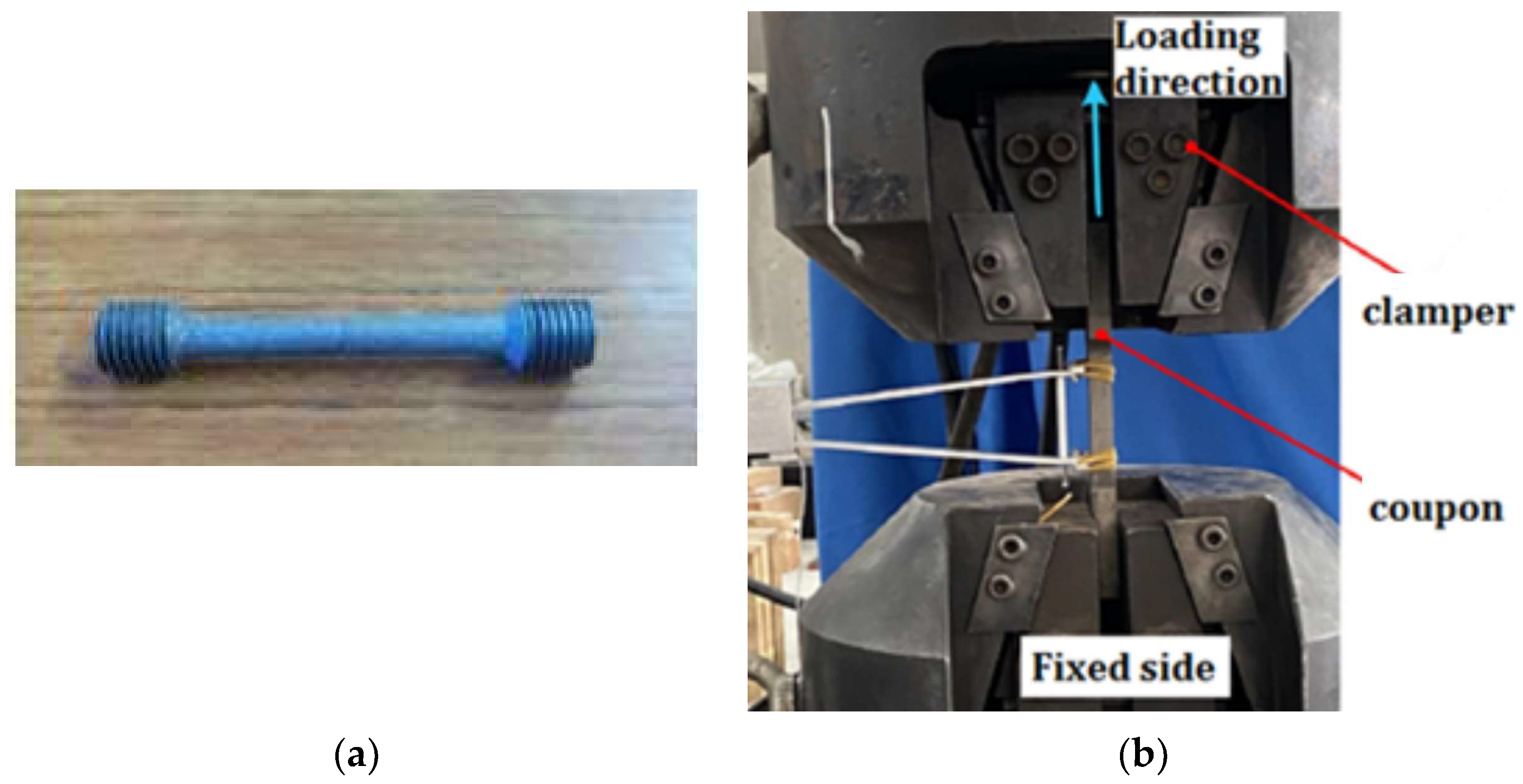
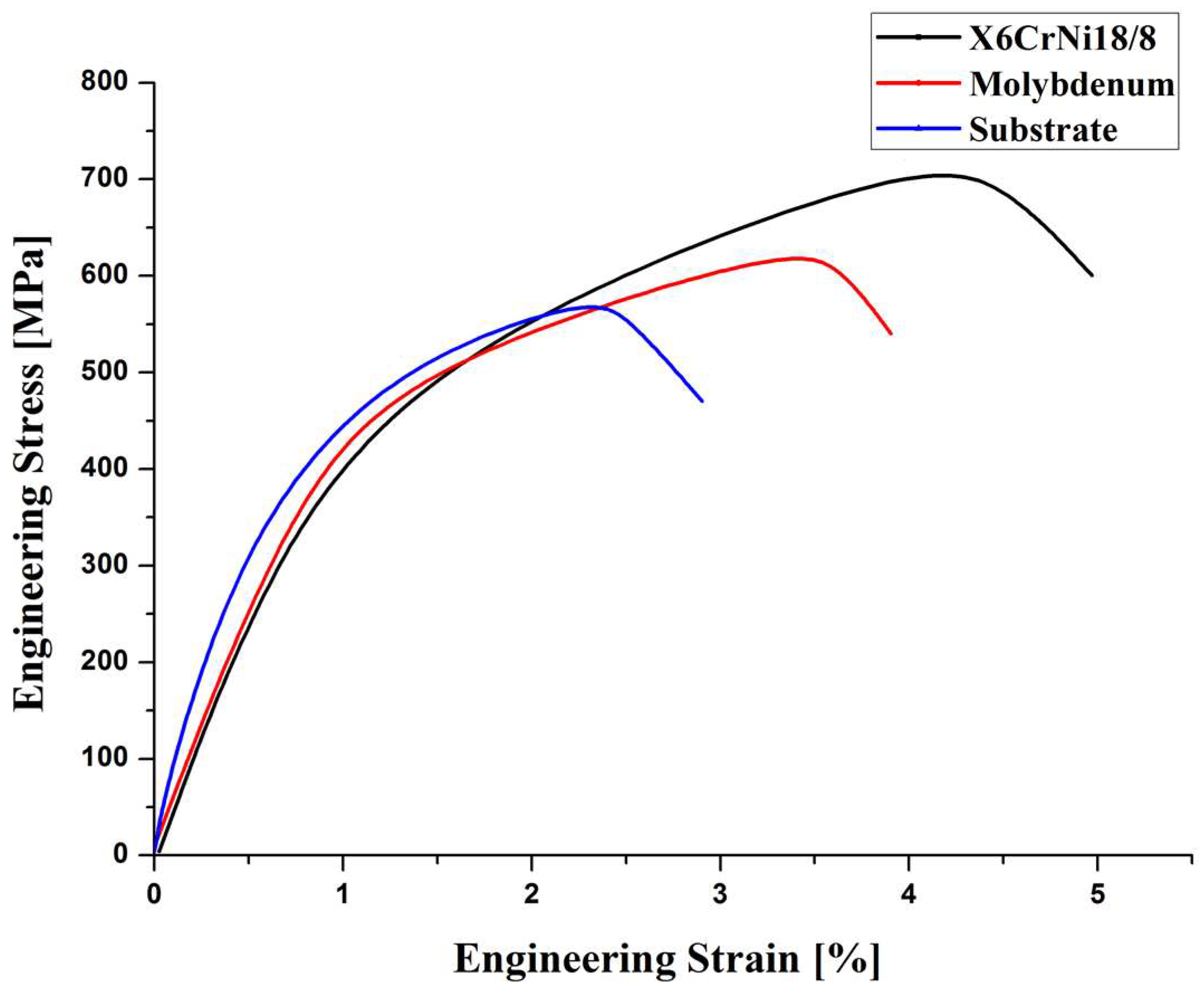
2.4.1. Uniaxial Tensile Test

The uniaxial tensile tests on cylindrical specimens of 5 mm diameter and 45 mm length were performed to extract the mechanical properties of the studied coatings. The tests were carried out on a tensile machine MT 3017 Tensile and Brinell Testing Machine, according to ISO 6892-1 standard [10]. Figure 2 presents a prepared sample for uniaxial tensile tests and the utilized testing setup.

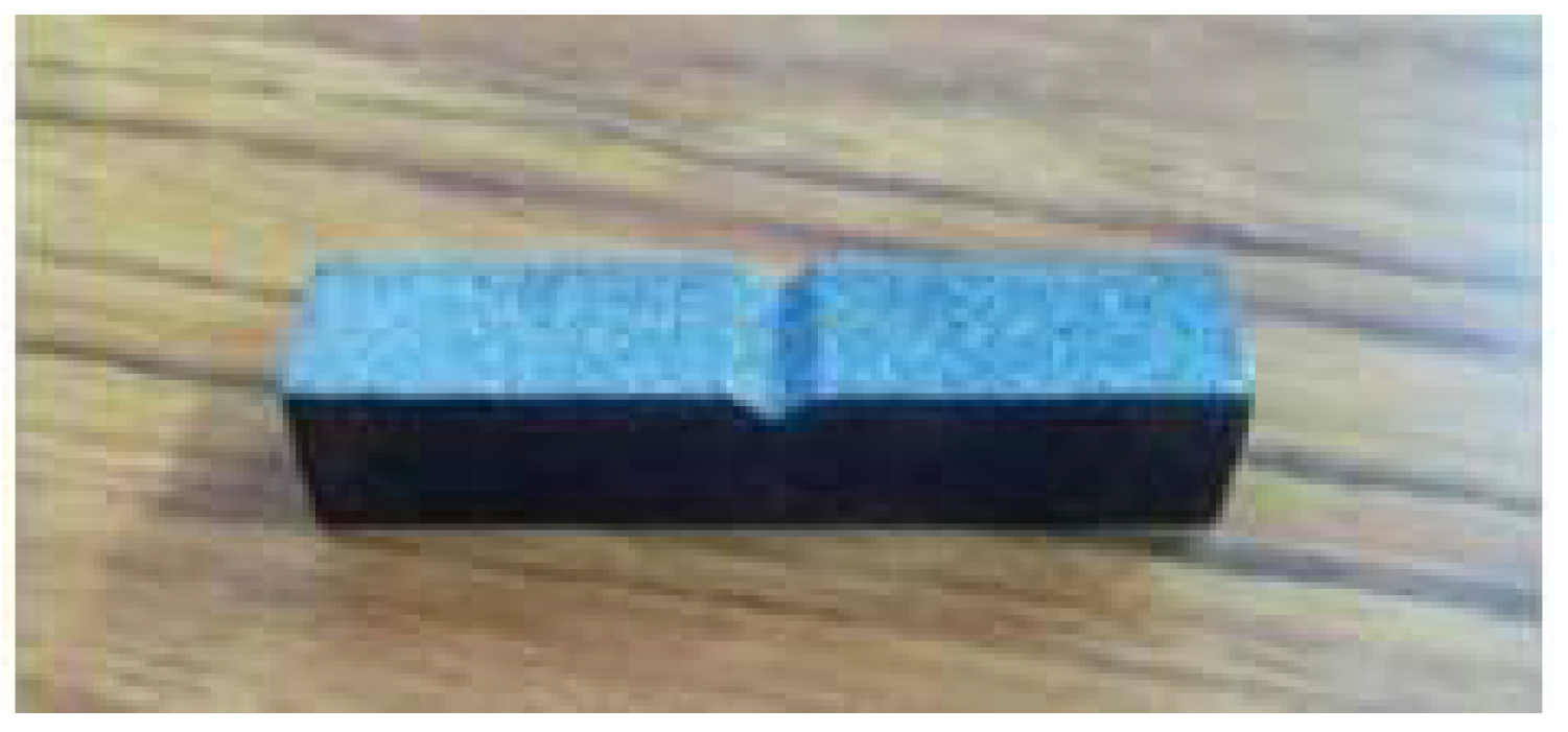
2.4.2. Hardness and Impact Resistance

Vickers hardness measurements of coatings and the substrate were carried out on polished surfaces of the different samples using Zwick B 3,212,001 equipment. A load of 249.1 N was applied for 15 s, and the average values were a series of 10 measurements. Charpy impact tests, using V-notch, were conducted on a MT 3016 Impact Tester, with a maximum capacity of 15 J, according to the ISO 179-2 standard [11]. Figure 3 presents the sample prepared for impact tests, with dimensions of 55 × 10 × 10 mm3.
The constraint factor (CF) was calculated using hardness (H) and yield strength (Y) values through Equation (1):
CF = H/Y,

3. Results

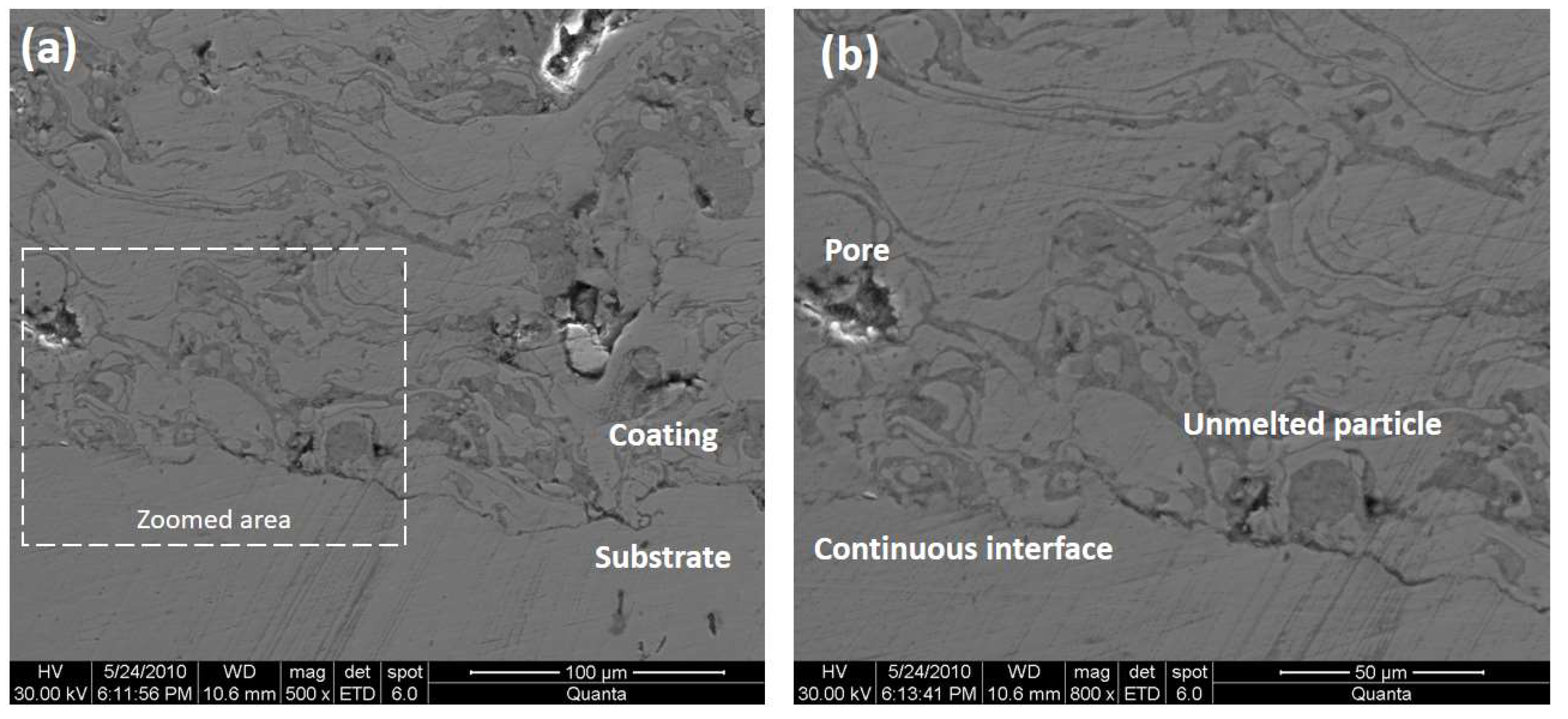
3.1. Microstructural Characterization

Figure 4a shows the cross-sectional back-scattering (BSE) image of the as-sprayed molybdenum coating. A zoom view is presented in Figure 4b, where porosity and a stratified lamellar microstructure are observed. From EDS analysis, only one phase can be identified as the molybdenum coating matrix, as previously verified by Ozgurluk [12], who used high-velocity oxygen fuel (HVOF) to produce refractory coatings. A certain oxygen level was detected in the detached region used for EDS analysis—16.3 wt.%—meaning that available oxygen reacted with molybdenum during the deposition. Additionally, other undesired features can be seen in Figure 4b, particularly pores and unmelted particles, resulting from the high strain of the particles during the solidification process. Finally, looking at the interface between the coating and substrate (Figure 5a), one can observe irregularities. Indeed, the mechanical properties will be affected by this characteristic. Bradai et al. [13] verified the oxide formation using a bond coat of Mo while depositing bearing steel coating onto 35CrMo4 steel. They inferred that this formation was responsible for better adhesion strength without the Mo-bonding coat.
Figure 5a shows the cross-sectional BSE image of the as-sprayed X6CrNi18-8 stainless steel coating. Figure 5b shows a magnified image indicated in the previous one. Comparing these images to those described for Mo coating, the morphology remained lamellar, but the round shape was more frequent. Interposed splats with some oxidation levels were also detected, and large pores were observed. However, the most remarkable feature is the morphology of the interface. In Figure 5b, a continuous interface turns complex to distinguish the coating and substrate characteristics. This can assure a much higher level of adhesion strength, which can result in different mechanical properties from those determined by Mo coating.
Further, the small impact force was not conducive to the combination of lamellar structure, allowing easy generation of large pores, especially in these regions. In Figure 5b, two phases can be identified using the image contrast. The bright areas are a Cr-rich binder phase, as later revealed by EDS (Cr ~12 wt.%). Variation in the grayscale of the Cr-rich phase can be observed, which can be attributed to the small number of carbides dissolved in the coating matrix and the interlayer oxidation (Oxygen ~12.4 wt.%).

3.2. Mechanical Properties

Figure 6 presents the stress–strain curve obtained for substrate and arc-sprayed coatings.
Figure 6 shows the increase in total elongation promoted by coatings concerning the substrate. At the same time, the strengths of coatings were higher than the substrate, leading to a positive effect in antagonist properties. The values of yield strength and total elongation extracted from these curves, as well as the Vickers hardness and impact resistance, are presented in Table 4.
Before discussing a possible correlation between mechanical properties, checking the hardness profiles determined from the top surface up to the interface is helpful. Figure 7 shows the hardness profile determined using Vickers hardness.
Looking at Figure 7, one can conclude that the hardness determined at the top surface is representative of the whole thickness. Only a slight reduction of values towards the interface is affected by the coating microstructures previously described (Figure 4 and Figure 5).
Defects are crucial to understanding crack propagation since they are stress concentrators. We obtained a much higher value for the Mo coating than stainless steel coating, as can be seen by looking at the impact resistances. This result is explained by the more compact and homogeneous microstructure of Mo coating compared to stainless steel coating.
On the other hand, the total elongation was smaller for Mo coating, impeding the correlation of the properties. In this fashion, the interface can play a vital role once the integrity is higher for stainless steel coating, justifying the difference in this mechanical behavior. The sensitivity of impact tests to internal defects is a well-known fact in the literature. A significant example is the application of this test for cast irons containing graphite. Al-Ghonamy et al. [14] demonstrated that the impact resistance could be doubled in value depending on the graphite morphology for the exact composition of cast iron.
Regarding resistance properties, yield strength, and hardness, one can conclude that the values followed an order from the substrate to X6CrNi18-8 coating: the higher the strength, the higher the hardness. In the next section, we will discuss the relationship between hardness and yield strength in detail.

4. Discussion

Performing tensile tests using a substrate/coating as a single system implies that the deformation processes will happen at different portions of samples, including the bulk, interface, and surface. On the other hand, there is an expectation to avoid the substrate effect during the indentation, as thermally sprayed coatings’ thickness is big enough to ultimately accommodate maximum depths during a hardness test. Therefore, the hardness and yield strength relationship (constraint factor) should be higher than the ratios reported for metals once the values obtained in tensile tests do not correspond exclusively to the coating response.
Pintaude [7] argued that an ideal value of constraint factor is a very restricted concept, in which the endless number of 3 is only valid for a specific group of bulk metals. With this point in mind, we built a chart with our results, including those obtained by Ham et al. [15] for HVOF coatings for comparison (Figure 8).
From the constraint factor value of substrates used here and in reference [15], we can note a decrease in HVOF coatings, while an increase is evident in our coatings. All values are higher than 3, a typical value for metallic materials. The values for ferritic/pearlitic steels agree with those determined by Uememoto et al. [16], which are larger than 4.
Following the discussions presented in reference [9], the increase in constraint factor can result from local microstructural differences. This reasoning fits well for stainless steel coating, which identified homogeneities within the microstructure. However, a local decrease in yielding point would be less expected for a Mo coating once we identified a more homogeneous microstructure, as observed in Figure 4. On the other hand, a decrease in hardness due to defects could explain the reduction in constraint factor values, as determined for the HVOF coatings. This is valid for the Cr3C2–25NiCr case, compared to other HVOF depositions, because it presented less porosity and, consequently, a higher constraint factor.
It is essential to mention the differences in test systems to assess the mechanical properties. Gärtner et al. [9] tested ‘micro-flat’ samples that were 0.5 mm thick. This means that the effect of substrate properties was eliminated. Conversely, Ham et al. [15] provided no geometric details of the tested samples. However, they demonstrated that the specimens followed the same system used here, i.e., the substrate was coated after the proper testing geometry was machined. Another critical issue in reference [15] is the need for standard deviation values of testing results, which made the reliability questionable.
Finally, there is a difference between the hardness determination between our investigation and reference [15]. Ham et al. [15] determined the nanoindentation of coatings, meaning that minute portions of material were assessed. Depending on the tested region, the hardness can increase or decrease, changing the local constraint factor. We have applied heavier loads to determine the hardness, making the effect of microstructural features and the coating less variable. Therefore, there is an opportunity to investigate the usefulness of the constraint factor to evaluate the effect of thermally sprayed coatings on metallic substrates to validate hardness as an indicator of strength.

5. Conclusions

Depositing two metallic coatings through the arc-spray technique, we have discussed the relationship between mechanical properties extracted from tensile tests and easy methodologies to express the strength and toughness of materials. From our described results and discussions, the following conclusions can be put forward:
-
Total elongation was dependent on the interface integrity, while the impact resistance was sensible for the level of defects;
-
Yield strength and hardness could be correlated. The value of this relationship (constraint factor) depends on the microstructure. Comparing other values reported in the literature showed that the testing details are critical to assertively conclude the use of the constraint factor determined from tests performed with coated substrates. Hardness applied with high loads seems suitable to estimate the resistance of coatings for structural parts.

Author Contributions

Conceptualization, R.Y. and G.P.; methodology, R.Y.; validation, M.A.B., A.I. and G.P.; formal analysis, L.B. and G.P.; investigation, Y.R and A.I.; resources, A.S.; data curation, G.P.; writing—original draft preparation, A.I.; writing—review and editing, L.B. and G.P.; supervision, A.S. All authors have read and agreed to the published version of the manuscript.

Funding

This research received no external funding.

Institutional Review Board Statement

Not applicable.

Informed Consent Statement

Not applicable.

Data Availability Statement

Not applicable.

Acknowledgments

The authors are deeply grateful to Mettalisation Ltd., Dudley, UK, for arc deposition of samples.

Conflicts of Interest

The authors declare no conflict of interest.

References

  1. Bhattacharya, A.K.; Nix, W.D. Analysis of elastic and plastic deformation associated with indentation testing of thin films on substrates. Int. J. Solids Struct. 1988, 24, 1287–1298. [Google Scholar] [CrossRef]
  2. Matthews, A.; Leyland, A.; Holmberg, K.; Ronkainen, H. Design aspects for advanced tribological surface coatings. Surf. Coat. Technol. 1998, 100, 1–6. [Google Scholar] [CrossRef]
  3. Paredes, R.S.; Amico, S.C.; d’Oliveira, A.S.C.M. The effect of roughness and pre-heating of the substrate on the morphology of aluminium coatings deposited by thermal spraying. Surf. Coat. Technol. 2006, 200, 3049–3055. [Google Scholar] [CrossRef]
  4. ASTM C633-13; Standard Test Method for Adhesion or Cohesion Strength of Thermal Spray Coatings. ASTM International: West Conshohocken, PA, USA, 2021; pp. 1–8.
  5. ASTM C1624-22; Standard Test Method for Adhesion Strength and Mechanical Failure Modes of Ceramic Coatings by Quantitative Single Point Scratch Testing. ASTM International: West Conshohocken, PA, USA, 2022; pp. 1–29.
  6. Ashby, M.F.; Jones, D.R.H. Engineering Materials 1: An Introduction to Properties, Applications and Design, 1st ed.; Elsevier: Amsterdam, The Netherlands, 2012; Volume 1. [Google Scholar]
  7. Pintaude, G. Hardness as an indicator of material strength: A critical review. Crit. Rev. Solid State Mater. Sci. 2022, in press. [Google Scholar] [CrossRef]
  8. Li, H.F.; Duan, Q.Q.; Zhang, P.; Zhang, Z.F. The Relationship between Strength and Toughness in Tempered Steel: Trade-Off or Invariable? Adv. Eng. Mater. 2019, 21, 1801116. [Google Scholar] [CrossRef]
  9. Gärtner, F.; Stoltenhoff, T.; Voyer, J.; Kreye, H.; Riekehr, S.; Kocak, M. Mechanical properties of cold-sprayed and thermally sprayed copper coatings. Surf. Coat. Technol. 2006, 200, 6770–6782. [Google Scholar] [CrossRef]
  10. ISO 6892-1:2019; Metallic Materials—Tensile Testing—Part 1: Method of Test at Room Temperature. ISO: Geneva, Switzerland, 2019; pp. 1–78.
  11. ISO 179-2:2020; Plastics—Determination of Charpy Impact Properties—Part 2: Instrumented Impact Test. ISO: Geneva, Switzerland, 2020; pp. 1–23.
  12. Ozgurluk, Y. Investigation of oxidation and hot corrosion behavior of molybdenum coatings produced by high-velocity oxy-fuel coating method. Surf. Coat. Technol. 2022, 444, 128641. [Google Scholar] [CrossRef]
  13. Bradai, M.A.; Braccini, M.; Ati, A.; Bounar, N.; Benabbas, A. Microstructure and adhesion of 100Cr6 steel coatings thermally sprayed on a 35CrMo4 steel substrate. Surf. Coat. Technol. 2008, 202, 4538–4543. [Google Scholar] [CrossRef]
  14. Al-Ghonamy, A.I.; Ramadan, M.; Fathy, N.; Hafez, K.M.; El-Wakil, A.A. Effect of graphite nodularity on mechanical properties of ductile iron for waterworks fittings and accessories. Int. J. Civil. Environ. Eng. 2010, 10, 1–5. [Google Scholar]
  15. Ham, G.S.; Kreethi, R.; Kim, H.J.; Yoon, S.H.; Lee, K.A. Effects of different HVOF thermal sprayed cermet coatings on tensile and fatigue properties of AISI 1045 steel. J. Mater. Res. Technol. 2021, 15, 6647–6658. [Google Scholar] [CrossRef]
  16. Umemoto, M.; Liu, Z.G.; Tsuchiya, K.; Sugimoto, S.; Bepari, M.M.A. Relationship between Hardness and Tensile Properties in Various Single Structured Steels. Mater. Sci. Technol. 2001, 17, 505–511. [Google Scholar] [CrossRef]
Figure 1. Arc Spray 234.
Coatings 13 00878 g001
Figure 2. (a) A sample for uniaxial tensile tests; (b) testing setup.
Coatings 13 00878 g002
Figure 3. A sample for Charpy tests.
Coatings 13 00878 g003
Figure 4. (a) Cross-sectional SEM image of the as-sprayed molybdenum coating, (b) zoomed area used to determine the local chemical composition.
Coatings 13 00878 g004
Figure 5. (a) Cross-sectional SEM image of the as-sprayed X6CrNi18-8 stainless steel coating; (b) zoomed area used to clarify the structural features.
Coatings 13 00878 g005
Figure 6. Stress–strain curves of studied coatings from tensile tests.
Coatings 13 00878 g006
Figure 7. Hardness profiles determined for studied coatings using the Vickers scale.
Coatings 13 00878 g007
Figure 8. Chart with constraint factor values determined for current investigated arc-sprayed and HVOF coatings studied in reference [15].
Coatings 13 00878 g008
Table 1. Chemical composition of the mild steel substrate, wt.%.
CSiMnPSFe
0.140.051.20.110.27bal
Table 2. Chemical composition of different filler materials, wt.%.
As-Sprayed MaterialsCNiMnCrMoFeOther
X6CrNi18-80.068318-bal0.2
Molybdenum----99-1
Table 3. Different settings for arc spray parameters 234.
Spray Parameters
Pressure4 bar
Pressure of the air3 bar
Wire feed speed0.06 m/s
Generator voltage30 V
Generator intensity100 A
Distance projection140 mm
Angle90°
Nozzle feed speed4 mm/tour
Table 4. Mechanical properties of studied coatings: yield strength and total elongation from the tensile test, Vickers hardness, and Charpy impact resistance.
MaterialYield Strength, MPaTotal Elongation, %Hardness, HV25Impact Resistance, J/cm2
X6CrNi18-8 coating535 ± 44.48± 0.07248 ± 134.4 ± 0.8
Mo coating430 ± 73.63± 0.09227 ± 108 ± 2
Substrate332 ± 42.24 ± 0.03136 ± 8n.d.
n.d.: not determined.
Disclaimer/Publisher’s Note: The statements, opinions and data contained in all publications are solely those of the individual author(s) and contributor(s) and not of MDPI and/or the editor(s). MDPI and/or the editor(s) disclaim responsibility for any injury to people or property resulting from any ideas, methods, instructions or products referred to in the content.

