1. Introduction
The Marangoni effect is a phenomenon of mass transfer between two fluids with different surface tensions where the fluid flows from a region of low surface tension to a region of high surface tension [
1,
2]. In nature, some insects can propel themselves rapidly by using the Marangoni effect without employing the oscillatory movements of legs [
1]. The Marangoni effect is also responsible for the formation of “wine tears” on glass walls. As the alcohol in the wine evaporates from the surface continuously, the alcohol concentration of the liquid on the glass wall drops even faster, causing the surface tension of the liquid on the glass wall to be greater than that of the liquid in the glass, so that the wine moves upward along the glass wall and eventually forms “wine tears”. The Marangoni effect can be used to induce nanosheets spread out into a thin single film. Compared with the films prepared by drip casting and spin coating, the film based on the Marangoni effect has a significant advantage in uniformity, a fast film-formation rate and simple operation [
2].
Shim et al. [
2] demonstrated a rapid interfacial assembly strategy for large-area graphene sheets. When EA (ethyl acetate) was injected into a water/N-methylpyrrolidone suspension of graphene, EA triggered the graphene sheets’ convective transport rapidly and assembled into a uniform graphene film of arbitrarily large areas in a matter of minutes. The Marangoni effect has important applications in different fields. For example, Wu et al. [
3] used Marangoni self-assembly technology to prepare large-area graphene films with a low friction coefficient (about 0.05) and developed a new lubrication system, which has broad prospects in engineering applications. Yoshida et al. [
1] proposed a Marangoni propelling microrobot integrated with a wireless photonic colloidal crystal hydrogel sensor for detecting water environments and transmitting environmental information.
Recently, the Marangoni effect has been used in the fabrication of flexible strain sensors, which convert mechanical strains into electrical signals [
4]. As the “nerve endings” in the Internet of Things world, flexible strain sensors are the key components of intelligent devices and wearable devices, which have a wide range of applications in human–computer interaction [
5,
6,
7], electronic skin [
8], health monitoring [
9,
10,
11], etc.
According to sensing principles, flexible sensors can generally be divided into resistance sensors [
12,
13], capacitive sensors [
14] and piezoelectric sensors [
15,
16]. Resistance sensors, which convert strains to resistance changes, have been widely studied because of their simple structures, high sensing performance, simple signal conversion mechanism and stable signal output. Moreover, flexible sensors can be roughly classified according to their microstructures, including full-filling [
17,
18], sandwich-like [
9,
19] and adsorption sensors [
20,
21]. The sandwich-like sensors, consisting of conductive films and two layers of flexible substrates, have received extensive attention owing to their high sensitivity and stability. The common methods of sensor preparation include spinning coating [
22], spraying [
9,
23], scraping [
24], rod coating [
25], printing [
12,
19], swelling/permeating [
26,
27,
28], self-assembly [
5,
29], layer-by-layer (LBL) assembly [
20,
30,
31], laser inducement [
32,
33,
34], chemical vapor deposition (CVD) [
35,
36], electrodeposition (ED) [
37], etc. Flexible strain sensors are generally composed of conductive materials and flexible substrates. Conductive materials play an important role in constructing conductive networks and generating resistance change under strain. Graphene (GN) [
12,
25], carbon nanotubes (CNTs) [
8,
9,
20], carbon black (CB) [
38], silver nanowires (AgNWs) [
29,
39] and conductive polymers [
37,
40] have been widely used as conductive materials. Flexible substrates show the function of supporting and connecting conductive materials, responding to stress and strain, which is crucial to the flexibility and stretchability of sensors. Flexible substrates such as polydimethylsiloxane (PDMS) [
9,
22], polyurethane (PU) [
8,
12,
15] and fabric [
41,
42] have been widely applied in the electronic field. Gauge factor (GF) is a factor used to estimate the sensitivity of strain sensors, which is defined as GF = (ΔR/R
0)/ε, where R
0 (Ω), ΔR (Ω) and ε (%) represent the initial resistance without strain, and the resistance change with strain and applied strain, respectively [
43,
44]. Sensitivity and the working range are a pair of parameters that restrict each other. The strategy of increasing sensitivity often reduces the working range and vice versa. Generally, the sensing performance of sensors is synthetically evaluated by their conductivity, sensitivity, working range, response time and cyclic stability [
43,
44].
Most of the sensors based on the Marangoni effect employ ultrathin graphene films as sensitive layers, all of which show high sensitivity and excellent sensing performance. Li et al. [
43] injected graphene/ethanol dispersion onto the surface of deionized (DI) water. Due to the Marangoni effect, ethanol with graphene sheets flowed from the region of low surface tension (ethanol) to that of high surface tension (DI water). As ethanol evaporated, graphene sheets collided and bonded at the liquid/air interface through π–π interactions. “Fish scale” graphene film was formed on the water surface with a thickness of 2.5–5.0 nm and high transparency (86%–94% at 550 nm). Ultrathin graphene film (UGF) strain sensors with a “fish scale” microstructure showed an ultrahigh sensitivity of 1037 GF at 2% strain and could be used to detect electrical signals generated by small deformation, such as pulse and sound waves. Similarly, Jia et al. [
44] skimmed the assembled graphene film to pre-stretched PDMS substrates. The strain sensor (pre-strain, 50%) based on the double-layer pleated graphene films showed high sensitivity (GF = 37.1), a wide working range (>50%) and excellent cyclic stability (ε = 20%, >5000 times). Jiang et al. [
45] transferred Marangoni self-assembled graphene films to patterned PDMS by skimming, and assembled them onto an interdigitated Ni/Au electrode to fabricate a high-performance piezoresistive pressure sensor. The sensor exhibited high sensitivity (1.04–1875.5 kPa
−1) and high durability (15,000 cycles) over a large linear detection range (1–40 kPa).
Inspired by the Marangoni effect, we prepared Marangoni-assembled ultrathin conductive films with GN and CNTs to exert their synergistic effect. After transferring the films twice onto flexible substrates and assembling them face to face, we obtained flexible strain sensors with high conductivity. Expensive instruments and complicated operations are not necessary in the fabrication progress, and the sensitivity, working range and cyclic stability of strain sensors are excellent. Compared with the reported Marangoni-based sensors, our fabrication process improves the utilization of carbonous nanomaterials and exerts the synergistic effect of GN and CNTs to adjust the sensitivity and working range of sensors.
2. Materials and Methods
2.1. Materials
The graphite paper was supplied by Beijing Jinglong Special Carbon Technology Co., Ltd. (Beijing, China). CNTs (carbon purity: >99 wt%; diameter: 5–15 nm; length: 10–30 μm) was purchased from Chengdu Organic Chemicals Co., Ltd. (Chengdu, China). 3M4910 tape was obtained from 3M China Co., Ltd. (Shanghai, China). PDMS (Sylgard 184 Silicone Elastomer) was provided by Dow Corning Corp. (Midland, MI, USA). Conductive silver paste was supplied by Shenzhen Woweisi Electronic Technology Co., Ltd. (Shenzhen, China). NaOH (superior purity) was provided by Damao Chemical Reagent Factory (Tianjin, China). Ethanol (95%, analytical purity) was purchased from Tianjin Jiangtian Chemical Technology Co., Ltd. (Tianjin, China).
2.2. Preparation of the Sensor
Preparation of graphene. GN was produced by electrochemical exfoliation method. The graphite paper (anode) was electrolyzed at 5.5 V, using the platinum electrode as the contrast electrode (cathode) and 1 mol·L−1 NaOH solution as the electrolyte. The electrolysis process was carried out in an ice bath and more than 100 mg product was obtained within 20 min. After the electrolysis process, the electrolyte solution was filtered through a 0.22 μm PTFE microporous filter membrane, and then the filter cake was washed to neutral with DI water. After drying at 50 °C for about 6 h, GN was obtained.
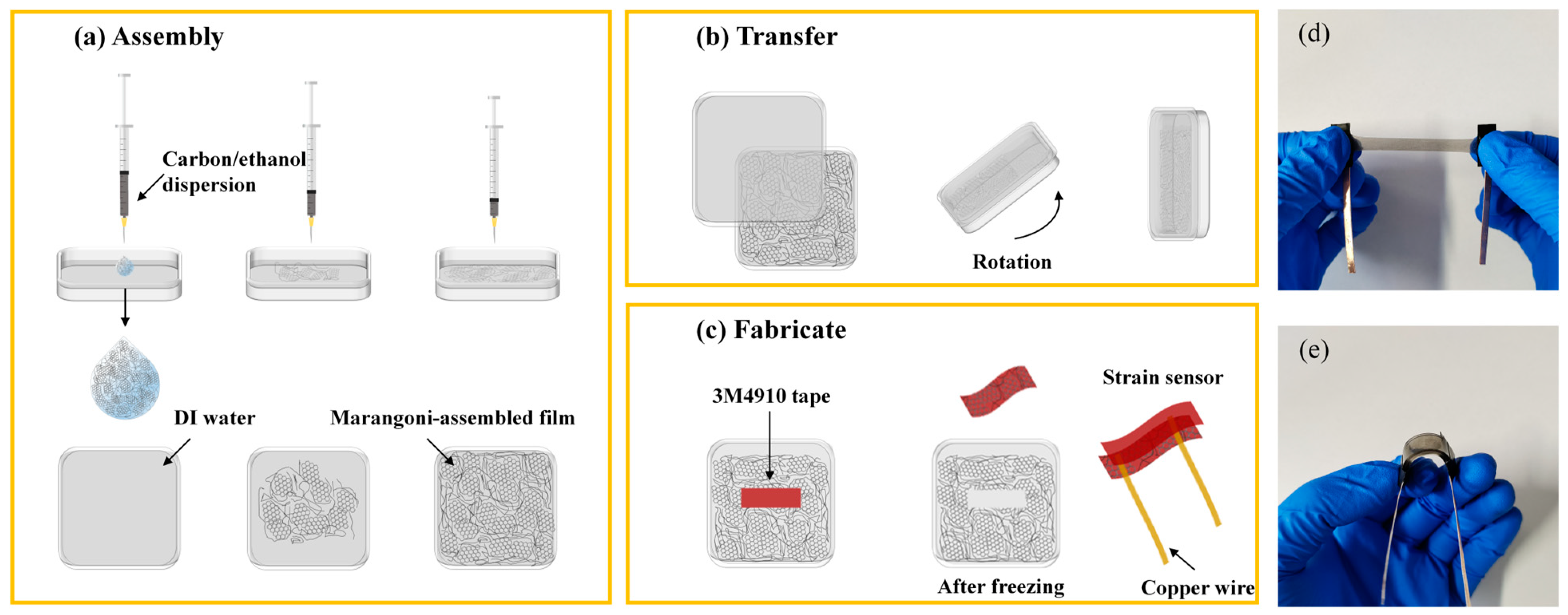
Fabrication of Marangoni-driven conductive film. We used GN and CNTs as conductive materials. A certain volume of carbonous nanomaterials/ethanol dispersion with the concentration of 1 mg·mL−1 was added dropwise onto the surface of 100 cm2 DI water in a plastic square petri dish. As the dispersion dropped in, the carbonous nanomaterials (GN or CNTs) gradually covered the water surface, forming a layer of continuous film in a few seconds. Then we put the matching lid on the petri dish tightly and flipped it carefully to transfer the film onto the lid. After that, the film on the lid was dried at 50 °C for 20 min.
Transfer of Marangoni-driven conductive film. The dried conductive film on the petri dish lid was pasted onto 3M4910 tape. A scraping plate was used to drive out the bubbles so as to make a thorough transfer of conductive film. After freezing at −20 °C for 15 min, the 3M tape (lost elasticity temporarily to avoid being stretched) was torn off, and the conductive film was transferred onto the stretchable 3M tape. In addition, the paste progress can be repeated again to increase their electrical conductivity. Moreover, the conductive film on water can be transferred to PDMS (main agent to hardener mass ratio 10:1, spun at 300 r·min−1 on the spin coater, cured at 45 °C for 6 h) by skimming method, which skims a layer of conductive film by PDMS with the plane size of 0.8 cm × 2.5 cm on a glass sheet.
Fabrication procedures of the strain sensor. A strain sensor was fabricated by combining two pieces of composite films face to face. The substrate of the composite film was 3M tape (3M4910) or PDMS, where only one layer of conductive film could be pasted to PDMS, while one or two layers of conductive film could be pasted to 3M4910 tape. In order to distinguish the number of the conductive film layers of the sensor, we named the 3M4910-based sensors composed of different layers of conductive film as the (m + n) sensor, where m and n, respectively, represented the number of layers of conductive film pasted on the 3M tapes. For example, (2 + 1) represented the sensor formed by a piece of 3M tape with two conductive layers and another piece of 3M tape with one conductive layer, while (1 + 0) represented a sensor composed of a piece of 3M tape with one layer of conductive layer and another piece of clean 3M tape without conductive film. For 3M4910-based sensors, if their names were not specified, they were (2 + 2)-type sensors. Copper wires were drawn by conductive silver paste at both ends of the conductive layer to form electrodes. The width of the conductive layer was 0.8 cm and the distance between the two electrodes was 2 cm. For clarity, a schematic diagram for the fabrication procedures of the 3M4910-based strain sensor and photos are presented in
Figure 1.
2.3. Characterization and Measurement
The morphologies of GN and CNTs were characterized by field emission scanning electron microscope (SEM, Regulus 8100, Hitachi, Tokyo, Japan) at an accelerating voltage of 3.0 kV, transmission electron microscopy (TEM, Talos F200x, FEI, Brno, Czechia) and atomic force microscope (AFM, Dimension Icon, Bruker, Karlsruhe, Germany). A thin layer of platinum was sputter-coated before SEM measurements. Raman spectrometer (inVia, Renishaw, Wotton-under-Edge, UK) was employed to characterize the quality of CNTs and GN with 532 nm laser. The thickness of Marangoni-assembled films was measured by an ellipsometer (M-2000v, J. A. Woollam Co., Inc., Lincoln, NE, USA). Sheet resistances of the conductive films were measured by a four-probe resistivity tester (RTS-8, Guangzhou Four Probe Technology Co., Ltd., Guangzhou, China) under 25 °C and 60% RH. A UV-visible spectrophotometer (TU-1900, Beijing Purkinje General Instrument Co., Ltd., Beijing, China) was employed to measure the light transmittance of the samples in the range of 400–800 nm. The strain-sensing behaviors were measured using an electrochemical workstation (VERTEX V16407, Ivium Technologies, Eindhoven, Netherlands) coupled with a universal electronic tensile machine (WDW-05L, Jinan Spai Technology Co., Ltd., Jinan, China) with the rate of 50 mm·min−1.
3. Results and Discussion
3.1. The Characterization of CNTs and GN
SEM, AFM and TEM were used to characterize the microstructure of carbon materials. As can be seen from
Figure 2a and
Figure S1a,b, CNTs are a one-dimensional structure with a pipe diameter of about 10–20 nm. In the natural state, CNTs are curled and intertwined, forming an interconnected network. GN exhibits a two-dimensional layered structure in
Figure 2b,c and
Figure S1c,d. Moreover, GN is composed of multiple stacked layers together with a large number of folds. These folds are easily disperses under a strong ultrasound, thus forming small transverse lamellae and causing cracks around the GN. TEM was used to analyse the microstructure of GN (
Figure 2d). The TEM image shows that the surface of the GN is relatively flat and the transverse size of the lamellae is about 1–2 μm. In
Figure 2e, the AFM image further proves that the transverse size of GN is about 1–3 μm and the thickness is about 1.4 nm, which means the GN has a large lateral dimension and thin thickness and may be composed of 1–3 layers of a GN monolayer [
43]. The cracks were observed around the graphene lamellar layer as well.
Raman spectroscopy was used to assess the quality of CNTs and GN, as shown in
Figure 2f. The value of I
D/I
G is critical to evaluate the degree of crystal defects of graphene derivatives. The larger the value of I
D/I
G, the more defects exist in the material; conversely, the smaller the value of I
D/I
G, the fewer defects exist and the more structured the material. The I
D/I
G values of CNTs and GN were 1.29 and 0.75, respectively, indicating the high quality of the CNTs and GN with few defects.
3.2. Effects of the Proportions of CNTs and GN
One-dimensional CNTs and two-dimensional GN can be combined as conductive materials to enhance their synergy. Marangoni-assembled films exhibit different structures and performance when CNTs and GN are mixed in different proportions, which is crucial for sensor design. GN nanosheets can easily slip during stretching, resulting in damage to the conductive network, which is beneficial to the sensitivity but limits the working range of sensors. CNTs have a certain tensile property due to their one-dimensional structure with a high length–diameter ratio, and are curly and tangled in their natural state. Even the sensor based on CNTs is stretched due to large strains, although the CNTs’ network is not completely destroyed, which benefits the conductivity and working range of the sensor.
In the process of Marangoni assembly, we injected 1 mg·mL−1 carbonous nanomaterials/ethanol dispersion with the volume of 0.5 mL, in which the CNTs’ mass proportions were 25%, 50%, 75% and 100%, respectively. When GN was used alone without CNTs, the Marangoni self-assembly phenomenon of the carbon nanomaterials was completely different to the GN/CNTs composite, so we will discuss the situation separately.
Compared with the 25% CNTs film (
Figure 3a and
Figure S2a,e), there were more CNTs distributed on the surface of the GN nanosheets when the mass ratio of CNTs and GN increased to 1:1, as shown in
Figure 3b and
Figure S2b. It could be clearly observed that the junctions between GN nanosheets were also overlapped by CNTs, and the conductive pathways were further increased. It is worth noting that the GN network was formed while CNTs were too sparse to form a single CNT network.
Figure 3c and
Figure S2c,f show the microstructure of the conductive film with 75% CNTs. It can be seen that it was not only GN nanosheets that were connected to a network, but CNTs were also connected to form a CNT network. While using 100% of CNTs, the conductive network obtained by self-assembly with the same mass of carbonous materials was tighter, as shown in
Figure 3d and
Figure S2d.
The thicknesses of the films with 50% CNTs and 100% CNTs were 28 nm and 38 nm, respectively, tested by the ellipsometer on polished silicon wafer substrates. Four kinds of conductive films were transferred to quartz plates, and the resistance of the films was measured by a four-probe resistivity tester. As can be seen from
Figure 3e, the sheet resistances of the conductive films with CNTs of 25%, 50%, 75% and 100% were 21.1 kΩ·sq
−1, 10.0 kΩ·sq
−1, 8.3 kΩ·sq
−1 and 7.3 kΩ·sq
−1, respectively. The conductivity increased successively mainly because the electrical conductivity of the CNTs (0.12 Ω·cm) used in the experiment was higher than that of the GN (1.57 Ω·cm).
We used 3M4910 tape as a flexible substrate, and pasted the self-assembled films twice on the tape. Two pieces of composite conductive films were assembled face to face with copper tapes as electrodes, then a strain sensor was obtained. We stretched the sensors using a tension machine with the rate of 50 mm·min
−1, and recorded the resistance change. As shown in
Figure 3f–i, the ratio of GN and CNTs affected the working range and sensitivity of the sensors. The working range broadened as the CNTs’ proportion increased, while the sensitivity decreased. GN has a lamellar structure, which means it can easily slip during stretching and result in damage to the conductive network [
43,
44]. When the composite film was stretched to large strains, CNTs worked as “bridges”, which was helpful to reduce the agglomeration between GN nanosheets, increase the number of conductive paths and enhance the overall electrical conductivity to a large extent. Therefore, a higher proportion of CNTs is helpful to protect the network and increase the working range.
The working range of the sensor with 75% CNTs was broader than that of the sensor with 100% CNTs because of the synergistic effect of GN and CNTs. When the CNTs’ network was completely destroyed under a large strain, GN with a large area could still play a role in connecting the CNTs. Therefore, the conductive network with 75% CNTs was less likely to be damaged than that with 100% CNTs.
3.3. Effect of Carbonous Nanomaterials/Ethanol Dispersion Volume on Properties of Sensors
The volume of the added dispersion affects the density of the self-assembled film when the water surface is limited. A total of 1 mg·mL−1 50% CNTs/ethanol dispersion with different volumes was added dropwise to a 100 cm2 water surface. In the self-assembly process, when less than 0.3 mL dispersion was used, the conductive film could not cover the entire water surface, while when more than 0.6 mL dispersion was added, the excess carbon material aggregated on the water surface or sank in the water.
Figure 4a–d and
Figure S3 show the SEM images of Marangoni-assembled films formed by 50% CNTs dispersion in different volumes. It can be seen that GN and CNTs completely covered the silicon substrate at the addition of the volume of 0.3 mL, forming good conductive paths. CNTs were also evenly distributed on the GN layer when the added volume was successively increased to 0.4, 0.5 and 0.6 mL. The sheet resistances of films self-assembled by different volumes of dispersions were 17.7 kΩ·sq
−1, 12.9 kΩ·sq
−1, 10.0 kΩ·sq
−1 and 8.5 kΩ·sq
−1, respectively, as shown in
Figure 4e. The more carbon materials that were used in self-assembly, the denser the conductive network, and the better the conductivity of the film.
As shown in
Figure 4f, the transmittance of the conductive film was tested with an ultraviolet–visible spectrophotometer. The films self-assembled from 0.3 mL and 0.5 mL dispersion had light transmittances of 83% and 74% at 550 nm, respectively. As the volume of dispersion increased, the density of the film increased, so the light transmittance decreased gradually.
As can be seen from
Figure 4g–i, the working ranges of sensors prepared by different volumes of dispersion are all over 170%, and the sensitivities are 2.9, 3.6, 5.7 and 3.9, respectively. With more and more carbon materials assembled on films, the GN and CNTs connected with each other even tighter, with a certain overlap area. The tighter the conductive network, the less likely it was to be broken. Therefore, when the sensor was stretched to large strains, the overlapped nanosheets and numerous CNTs were more helpful to avoid the network being damaged totally, which increased the working range and decreased the sensitivity of the sensor. However, the sensitivity of the sensor from 0.5 mL dispersion was higher than that of the sensor from 0.4 mL dispersion, possibly because the aggregation between nanomaterials made the sheets slip more easily, resulting in the film being more prone to fracturing.
3.4. Effect of Layers of Conductive Films on Properties of Sensors
The number of conductive films transferred to the substrate has an important effect on the conductivity of the sensor. In the experiment, we pasted conductive films (50% CNTs film assembled by 0.5 mL dispersion) at different times with the 3M tape and assembled them face to face to fabricate sensors with different layers of conductive films. It is worth mentioning that the conductive film could be completely transferred using the 3M tape firstly, and a small part of the film was left in the second pasting because the stickiness of the 3M tape reduced a lot after the first pasting. After pasting twice, the stickiness of the tape was too weak to paste any film.
As shown in
Figure 5a, the transparency of the films decreased together with the total paste times. The (2 + 2) sensor still exhibited good transparency and the printed words “strain sensor” under the films could be observed clearly. The resistance of the sensors with different layers of conductive films increased in turn with the decrease in conductive film layers, shown in
Figure 5b. In other words, the more conductive materials that were transferred to the substrate, the conductive layer was thicker, and the conductivity of the sensor was better.
Electrical signals were collected under constant tension, and the resistance change is shown in
Figure 5c–f. The working ranges of sensors with different layers of conductive films were 193% (2 + 2), 112% (2 + 1), 85% (1 + 1) and 61% (2 + 0). As the thickness of the conductive layer and the content of carbon materials increased, the network was harder to break and the working range of the sensor increased as a result.
The sensitivity of the sensors (2 + 2), (2 + 1) and (1 + 1) increased from 5.7 to 7.3 and 9.3, respectively. In other words, the sensors’ sensitivities became higher and higher as the thickness of the conductive layers and the content of carbon materials decreased because the conductive network became easier to break. Moreover, the (2 + 0) sensor was less sensitive than the (1 + 1) one because these two layers of conductive films were pressed tightly together and the conductive network was not so easy to damage.
The (2 + 2) sensors responded to different strains repeatedly with the rate of 50 mm·min
−1, as shown in
Figure 5g. ΔR/R
0 increased as the sensor was stretched, and exhibited basically consistent performance under the same strain, showing good recovery performance and stability. The microstructure of the film after repeated stretching and recovery with the strain of 30% is shown in
Figure S4.
Cyclic stability is an important performance measurement for sensors. In
Figure 5h, the 3M-based sensor (made of 0.5 mL 50% CNTs/ethanol dispersion) was repeatedly stretched to ε = 10% at a rate of 20 mm·min
−1. After cycle testing for a long time, the electrical signal basically remained stable and the peak shape remained consistent.
The (2 + 2) sensor was applied to the joints of the human body to detect the resistance change during movement, as shown in
Figure 5i–k. When the sensor was fixed at the second joint of the index finger and bent to about 45°, the sensor responded quickly and sensitively, with ΔR/R
0 reaching 4. When the bend degree increased to the maximum (about 120°), ΔR/R
0 raised to about 15. In addition, when the finger repeated the same bending motion several times, the electrical signals were similar, due to the sensor’s good accuracy and repeatability.
The sensor was affixed to the wrist and knee to detect changes in electrical signals caused by different joints, as shown in
Figure 5j,k. The relative resistance increased as the wrist joint gradually bent, and decreased as the joint gradually returned to the straight state. When the wrist was bent inward by about 30°, ΔR/R
0 increased to about 0.4, and when it bent inward by about 45° (maximum), ΔR/R
0 increased to about 0.7. Moreover, when the tester subjected the sensor on the knee to a kick back motion, the electronic signal responded quickly, and ΔR/R
0 reached about 0.2. The sensor made from 50% CNTs proved its ability to detect human body action.
3.5. Effect of Substrates on Properties of Sensors
A flexible substrate is an important part of a sensor, as it affects the structure and function of the sensor. In order to explore the influence of substrate types on the performance of the sensor, the sensors based on 3M4910 and PDMS were fabricated using the conductive films formed by carbonous materials/ethanol dispersion with 50% CNTs and 100% CNTs, respectively.
The 3M4910-based sensor was fabricated by using 3M4910 tape to paste a 50% CNTs film twice face to face, while the PDMS-based sensor was fabricated by skimming the conductive film twice. No matter which kind of material was used as the flexible substrate, the sensitivity and working range of the sensors showed the same trend as the proportion of CNTs; that is, the sensor with 100% CNTs, exhibited a wider working range and lower sensitivity than that with 50% CNTs, as shown in
Figure 6.
When the proportion of CNTs was the same, the working range of the 3M4910-based sensor was much larger than that of the PDMS-based sensor because 3M tape has a higher fracture strain (more than 1100%). Even if the 3M4910-based sensor was stretched to an extremely high strain and lost its conductivity totally, the 3M tape remained unbroken. When the PDMS-based sensor was stretched so there was a sharp increase in resistance, the PDMS ruptured at the same time. The sensitivity of the PDMS-based sensor was slightly higher than that of the 3M4910-based sensor, which may be caused by the harder PDMS material and there being less carbon material.
3.6. GN Strain Sensor
When using GN/ethanol dispersion without CNTs to prepare conductive films through Marangoni self-assembly, the experimental results were completely different from the case with CNTs. At least 3 mL of GN/ethanol dispersion was required to form a dense GN film on a 100 cm
2 water surface, while when using the dispersion containing 50% CNTs and 50% GN, only 0.5 mL dispersion was needed to form a self-assembled film of the same area. The SEM images, as shown in
Figure 7a,b, exhibit GN nanosheets stacked on the top of each other similar to “fish scales”. The GN film was as thick as 4 μm, and the average sheet resistance of the GN films was 1.4 kΩ·sq
−1, measured by AFM and a four-probe resistivity tester, respectively. A large number of bubbles and cracks occurred frequently when we transferred the GN films on water to petri dish lids, which limited the transfer of the GN films to 3M tape by pasting. Therefore, we used PDMS as the flexible substrate to skim the GN films repeatedly, and the average resistance of the GN sensors fabricated face to face was 10.9 kΩ.
We stretched the GN sensors at the rate of 50 mm·min
−1 and recorded the change in resistance to obtain the strain−ΔR/R
0 relationship diagram, as shown in
Figure 7c. GN sensors exhibited a smaller working range (78%) and higher sensitivity (GF = 34) than GN/CNTs sensors, mainly due to the GN nanosheets slipping very easily and causing resistance changes when the film was stretched without the overlapping of CNTs.
The GN sensor was repeatedly stretched to different strains and recovered at the stretching rate of 50 mm·min
−1, and the results are shown in
Figure 7d,e. The ΔR/R
0 was obviously different under different strains, and was basically consistent under the same strain, showing good recovery performance and stability. As shown in
Figure 7f, the response and recovery time of the GN sensor were about 110 ms and 250 ms, respectively, which means the sensor responses were fast enough to be applied in reality.
The GN sensor also exhibited excellent cyclic stability. In
Figure 7g, the sensor was stretched to ε = 10% with the rate of 100 mm·min
−1. After 8000 cycles of testing, the electrical signal remained stable. In conclusion, the test shows that the sensors have excellent cyclic stability and can meet the requirements of electronic devices.
As shown in
Figure 8a–c, when the GN sensor was stretched together with the bend and recover of the finger, wrist and knee, the resistance changed quickly and ΔR/R
0 was higher than that of the 50% CNTs sensor because of the high sensitivity of the GN sensor. In addition, the GN sensor could detect subtle movements of the human body. In
Figure 8d–i, the sensor was successfully applied to detect the mouth opening, swallowing, saying “hi”, a frown, a blink and the pulse beating, and all of these output stable and reliable electrical signals. The experiments have proved that our strain sensors show great potential in real-time motion detection and can hopefully be applied in reality.
4. Conclusions
In this paper, we designed high-performance flexible strain sensors with a simple strategy. Ultrathin GN/CNTs conductive films were self-assembled on the water surface in a few seconds due to the Marangoni effect. The sheet resistance, optical transmittance (at 550 nm) and thickness of the Marangoni self-assembled film (with the mass ratio of CNTs and GN 1:1) were 8.3 kΩ·sq−1, 74% and 28 nm, respectively. After transferring the films to flexible substrates twice and packaging them face to face, flexible strain sensors with high sensing performance were obtained. The mass ratio of CNTs and GN and overall carbon content exhibited an enormous influence on sensors’ properties, especially their sensitivity, working range, conductivity and transparency. The synergistic effect between CNTs and GN was helpful for the conductivity and working range of sensors because of the combined network structure. With the increase in overall carbon content, the conductivity and working range of sensors increased, while their sensitivity and optical transmittance decreased, for the reason that tighter and thicker conductive networks were vulnerable to being destroyed. The sensors made of the Marangoni self-assembled film using 0.5 mL carbonous nanomaterials/ethanol dispersion with 50% CNTs based on 3M4910 showed satisfactory sensitivity (GF = 5.7), a large working range (193%) and good cyclic stability. The sensors made of the film assembled by 3 mL GN/ethanol dispersion based on PDMS exhibited high sensitivity (GF = 34), a wide working range (78%) and excellent cyclic stability (ε = 10%, >8000 cycles). In addition, they both performed outstandingly in sensing different strains with a short response and recovery time. The experimental results indicate the remarkable potential for the strain sensors to be applied in human motion detection.


