Article

Study on the Tribological Properties of Micro-Al2O3 Modified Carbon Fiber Hybrid-Reinforced Polymer

1
College of Mechanical and Transportation, Southwest Forestry University, Kunming 650224, China
2
Institute of Civil Engineering, Southwest Forestry University, Kunming 650224, China
*
Authors to whom correspondence should be addressed.
Coatings 2023, 13(7), 1227; https://doi.org/10.3390/coatings13071227
Submission received: 24 May 2023 / Revised: 2 July 2023 / Accepted: 6 July 2023 / Published: 9 July 2023

Abstract

:
Micro-sized Al2O3-modified carbon fiber hybrid reinforced polymer composites (CFHRP) were prepared using the vacuum-assisted resin transfer molding (VARTM) process, and friction and wear tests were performed on an MRTR-1 multifunctional friction and wear tester to study the effect of carbon fiber surface doping with trace amounts of Al2O3 and its content on the tribological properties of carbon fiber reinforced polymer composites. The surface morphology of the composite material was characterized using a three-dimensional confocal laser scanning microscope (LSM). The results showed that under dry friction conditions, the wear behavior of the composite material with micro-Al2O3 added was mainly abrasive wear and adhesive wear. Under the condition of water lubrication, the friction coefficient of the composite material with micro-Al2O3 added was higher than that of the carbon fiber/epoxy resin-based composite material without Al2O3, and the abrasive wear and adhesive wear were significantly reduced. In addition, under the condition of water lubrication, the cooling and boundary lubrication of water played a dominant role in the tribological behavior, so the influence of transfer film on the tribological behavior of the composite material was smaller than that under dry friction conditions. When the micro alumina content is 6%, the friction and wear reduction of CFHRP composite material are improved under water containing conditions. Under dry friction conditions, the content of micrometer alumina has a minimal effect on the change in friction coefficient.

1. Introduction

Carbon fiber-reinforced composite materials (CFRP) have excellent properties such as small specific gravity, excellent heat resistance, low coefficient of thermal expansion, high thermal conductivity, corrosion resistance, and good conductivity compared to traditional materials. The specific strength and specific modulus of composite materials formed with resins are about three times higher than those of steel and aluminum alloys. Therefore, as a new type of engineering composite material, it is applied in various fields. Carbon fiber-reinforced composite material (CFRP) is currently used in the shells of “Delta” carrier rockets, “Trident” II (D5), “dwarf” missiles, and other fields. It is widely used in military industry [1] and aviation [2,3]. At home and abroad, the weight of ultra light golf clubs made of carbon fiber pipes is only about 50 g, while the steel body weighs over 120 g [4,5]. While reducing weight, the carbon fiber material makes the club more elastic and resilient. The slide rails made of carbon fiber tubes are used in photography and camera equipment, which have a beautiful appearance and are easy to use, especially their lightweight and load-bearing characteristics, making them very suitable for outdoor photography and carrying. Carbon fiber composite materials are suitable for different parts of the drone body, arms, and wing frames. Compared to aluminum alloy, the weight reduction effect of 30% can improve the aircraft’s endurance and load capacity. The advantages of carbon fiber materials such as high tensile strength, corrosion resistance, energy absorption and seismic resistance, and stable chemical properties also effectively ensure the service life of the human-machine. It also appears in civil engineering construction, especially in bridge construction where it is widely used [6]. As bridges are mostly built-in wet and weathered erosive exposed environments, the anti-slip, corrosion, and deformation resistance of the material becomes its main consideration [7], and the excellent frictional properties of CFRP make them gradually become indispensable materials for bridge construction (Mei, Kuihua [8] et al.). Through the application study of the first carbon fiber fabric cable-stayed bridge in China, the results showed that all sections of the bridge could meet the ultimate load carrying capacity. On reinforced precast segmental bridge columns [9], CFRP also showed excellent performance, with reduced concrete damage after repair using CFRP compared to the original specimens, and the main damage pattern of the repaired specimens was the relative slip between segments. In contrast, when CFRP-reinforced low corrosion bridge columns, it can significantly reduce the ultimate displacement of bridge columns and improve their ductile performance and deformation capacity [10]. Using CFRP in bridges avoids occurring slippage between metal and concrete members, and the coefficient of friction matters in its ability to inhibit slippage and affect the anchorage effect when strengthening bridges. It is known that the larger the friction coefficient is, the better the anchorage performance of CFRP [11]. Therefore, it is especially important to study the frictional wear behavior of CFRP under different working conditions. Under dry conditions, the wear rate of the composite of carbon fiber and aluminum mesh increased with the increase of sliding speed, and the experimentally measured friction coefficient was 0.175 [12]. In contrast, under water-lubricated conditions, composites such as CFRP maintain a lower coefficient of friction and present better wear resistance compared to dry friction conditions [13]. Currently, the use of modified particles has become one of the important methods for improving the frictional wear properties of CFRP. Österle, W. et al. investigated the role of silica nanoparticles in friction and wear reduction of polymer composites and showed that, under dry friction conditions, silica nanoparticles form a silica-based protective film on the surface of polymer composites due to the thermal effect of the friction process, which gives the mixed composites good friction and wears reduction properties [14]. Wang, Zhi, et al. [15] studied the influence of micro amount of Al2O3 doped on the surface of carbon fiber and its content on the mechanical properties of carbon fiber-reinforced polymer composite strength of materials. The interlaminar fracture toughness and flexural strength of the composite without micro alumina are 348 J/m2 and 682 MPa, respectively. However, the interlaminar fracture toughness and flexural strength of the modified composite reached 522 J/m2 and 759 MPa, respectively. Compared with the traditional carbon fiber, the thermal properties of the composite were improved after adding trace Al2O3 into the layer. In contrast, the use of modified particles to improve the friction and wear reduction properties of carbon fiber composites in different environments has been less studied. In this experiment, researchers attempted to disperse micro-Al2O3 particles into CFRP matrix to prepare carbon fiber-reinforced composites (CFHRP). They mainly investigated the frictional wear behavior of CFHRP [16]. Frictional wear tests were carried out under different working conditions to provide a parametric basis for improving the friction reduction performance of CFHRP. Among them, the main purpose of hybridization was to optimize the frictional wear performance of high-performance fiber-reinforced composites.

2. Materials and Methods

2.1. Materials and Specimen Preparation

The CFRP was prepared by TC-35 (12K480g) twill carbon fiber cloth, the performance index of carbon fiber cloth is shown in Table 1, and ER5072 epoxy resin was used as the base material. The modified particles’ micro-Al2O3 powder with the average particle size of 3 μm and the SEM image of micro-Al2O3 powder (shown in Figure 1) were selected.
Firstly, the carbon fiber cloth (300 mm × 350 mm) was layered and sealed according to the required thickness, and the dispersed micro-Al2O3 epoxy resin solution was infused into the sealed carbon fiber cloth using a negative pressure vacuum pump until the carbon fiber cloth was completely infiltrated by the epoxy resin. Repeat the above process, adjusting the mass fraction of micron alumina in the epoxy resin solution each time, and finally determine the mass fraction of micron alumina as 0%, 1%, and 6%, respectively. Keep the vacuum pressure −0.1 Mpa and cool at room temperature (20 °C ± 3 °C) for 24 h to ensure the epoxy resin is completely infiltrated and cured. The CFHRP were prepared using a vacuum-assisted resin transfer molding process [17,18], and the vacuum-assisted resin transfer molding process is shown in Figure 2, and the carbon fiber composites with micro-Al2O3 (wt%) content of 0%, 1%, and 6% prepared in this study are named in Table 2.

2.2. Characterization

The friction and wear performance test of CFHRP was conducted in the MRTR-1 multifunctional friction and wear tester, and the pin-disk friction test equipment and experimental procedure are shown schematically in Figure 3.
The size of the lower CFHRP is 40 mm × 40 mm × 3 mm. Before the test, the CFHRP was put into an anhydrous ethanol beaker, cleaned for 15 min using an ultrasonic cleaner, dried quickly with a hairdryer, and weighed for the specimen. The upper specimen is a steel cylindrical pin, its size is Φ5 mm × 15 mm, and the chemical composition and hardness are shown in Table 3. The upper and lower specimens are clamped in Figure 4.
The frictional wear characteristics of CFHRP were studied under a normal load of 20 N, a rotational speed of 100 r/min, and a friction time of 120 min with water lubrication and dry friction conditions. All tests were conducted at room temperature (20 °C ± 3 °C) and relative humidity of 70% ± 5% under standard atmospheric pressure. To avoid chance factors, each group of tests was conducted two to three times. The friction coefficient was recorded continuously for the online data acquisition system of the testing machine, and the data acquisition interval was 10 s. After the friction experiment, the weight of the CFHRP after friction was measured using a FA324C multifunctional electronic balance with a division value of 0.01 mg. The wear rate was calculated according to Equation (1) [19]:
δv = Δm/ρFS·
where δv is the volumetric wear rate, mm3/N·mm2; Δm is the wear weight loss, mg; ρ is the density of the test material, g/cm3; F is the normal load, N; S is the wear distance. The specimens were observed by OLYMPUS-OLS4000 three-dimensional confocal laser scanning microscope (LSM) from Olympus Tokyo, Japan, and the crystalline composition of the specimens was characterized by an Ultima Ⅳ X-ray Diffractometer (XRD) from Rigaku, Japan.

3. Results and Discussion
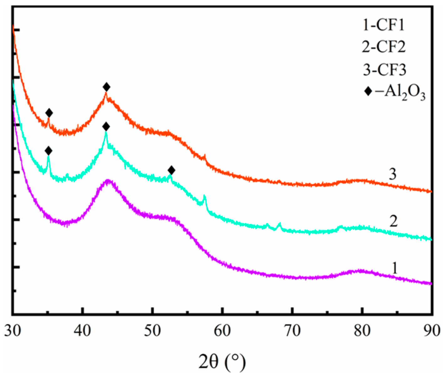
3.1. XRD Analysis

Figure 5 shows the XRD diffractograms of the three specimens, CF2 presents diffraction peaks representing the Al2O3 phase at (see curve 2) 2θ = 35.1°, 43.3°, and 57.3°, and CF3 presents diffraction peaks representing Al2O3 phase at (see curve 3) 2θ = 35.0° and 44.5°, CF1 does not find diffraction peaks of Al2O3 phase in the whole spectrum (see curve 1) This indicates that the specimens CF2 and CF3 successfully dispersed micro-Al2O3 in the carbon fiber plate, while the Al2O3 diffraction peak of CF2 is higher than that of CF3, which is related to the mass fraction of Al2O3 added, showing that the three specimens have different mass fractions of Al2O3 content, which provides a basis for comparison in the post-friction test.

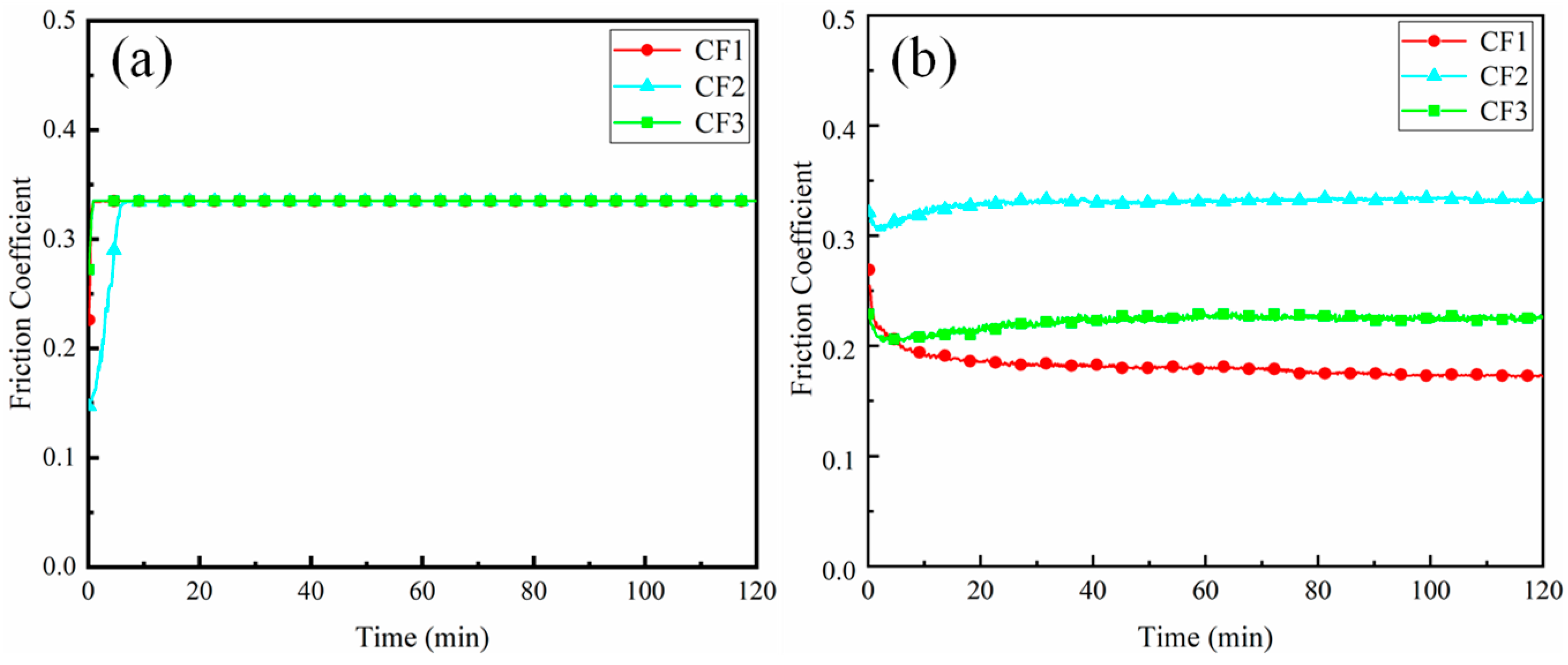
3.2. Change in Friction Coefficient of CFHRP under Dry Friction and Water-Lubricated Friction
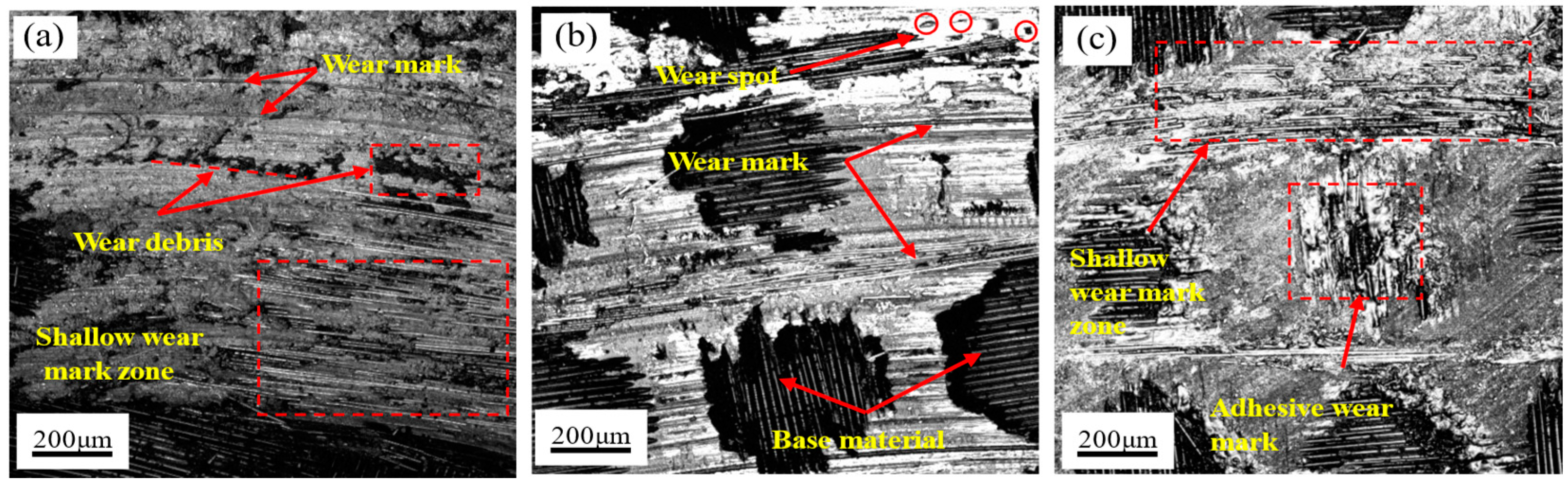
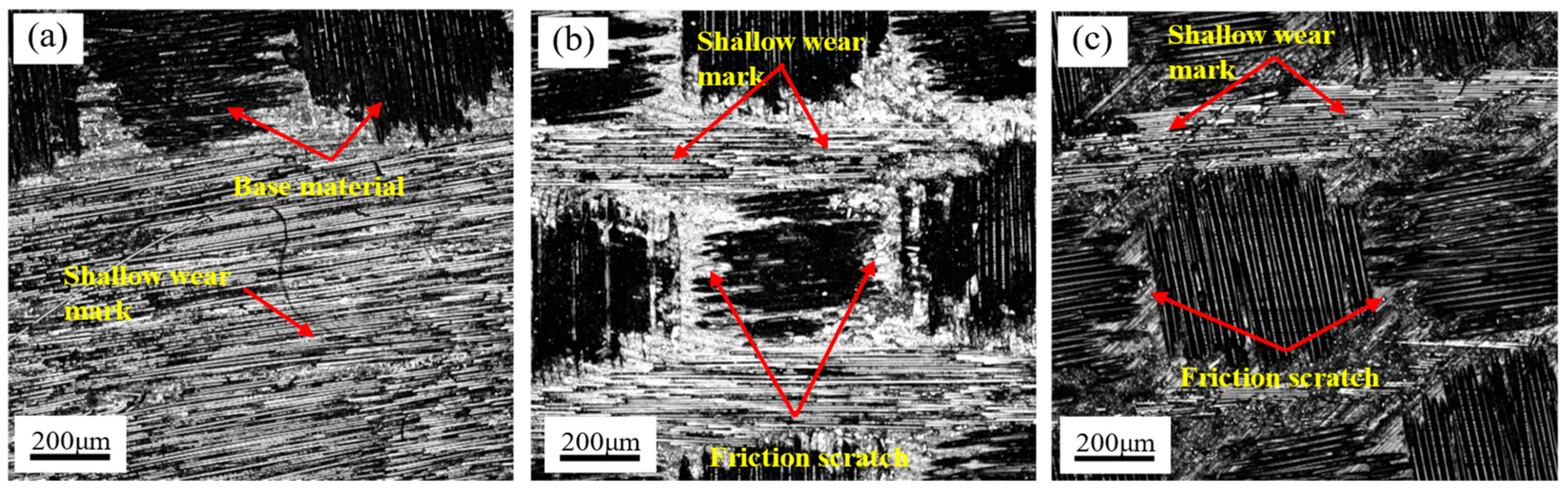
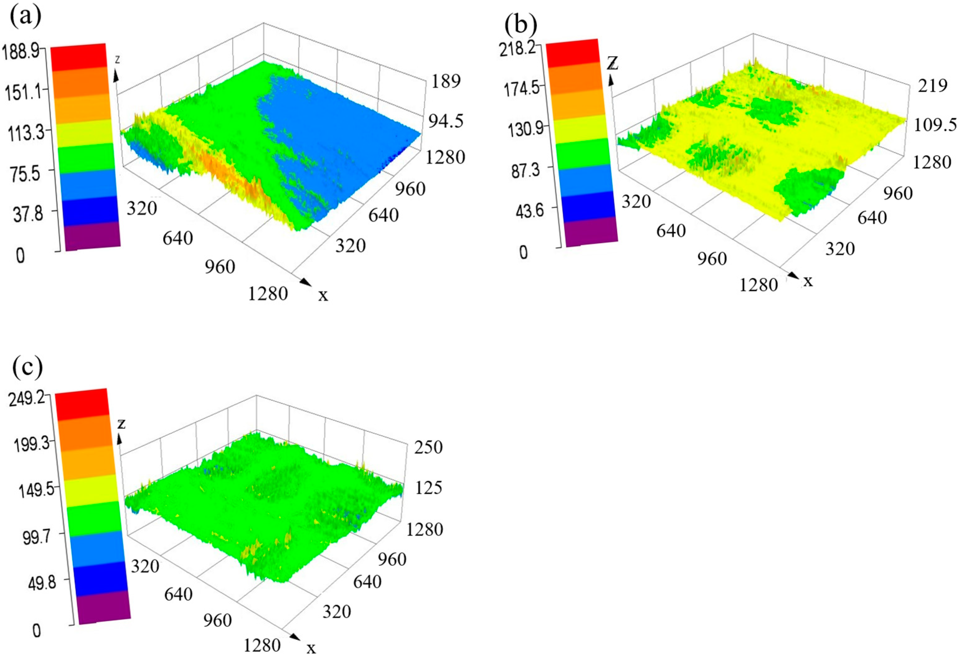
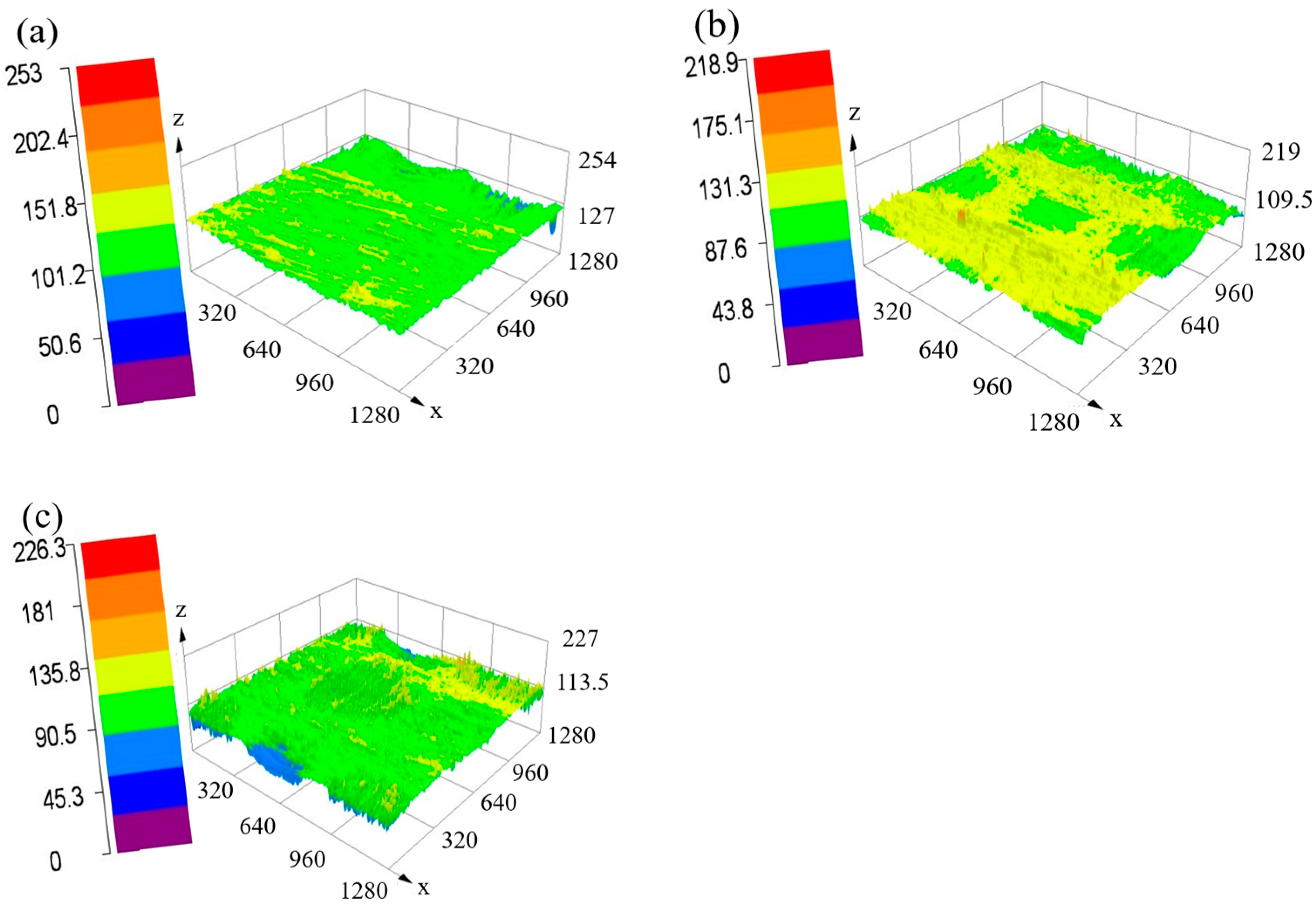
Figure 6a,b show the curves of the friction coefficient of the three materials with time under dry friction and water-lubricated conditions. It can be seen that the friction coefficient of all tests under dry friction conditions will rise rapidly within 2 min, and then gradually tends to a stable state with the increase of friction time, which is mainly due to the relatively rough surface of the specimen at the beginning of friction and the plowing effect of the micro-convex body of the upper specimen on the surface of the friction specimen, which will lead to a sharp increase in the coefficient of friction. Carbon fiber has the characteristics of self-lubricating plastic. When sliding occurs, the epoxy resin on the surface of the carbon fiber gradually wears, so that the carbon fiber is exposed. As the carbon fiber wears, the upper specimen and the lower specimen are in the grinding stage, which effectively reduces the frictional wear of the specimen and keeps the friction coefficient at a fixed value. The friction coefficient under the condition of water lubrication will drop sharply within 6 min and finally will slowly tend to a stable state. As the friction is in the mixed stage of dry friction and water lubrication at the beginning of the friction, and as the friction proceeds the friction coefficient shows a sharp decrease and then slowly stabilizes, the boundary lubrication effect of water makes the composite material enter the stable wear stage, which is consistent with the results of Junhong Jia [13] et al. The friction coefficients of the three specimens after stable wear were ranked: under dry friction conditions, the friction coefficients of CF1, CF2, and CF3 were stable at 0.33; under conditions with water lubrication, the friction coefficient of CF2 was greater than that of CF3, while the friction coefficient of CF1 was the lowest among the three.
In summary, the results show that the specimens all exhibit lower friction coefficients under friction conditions containing water lubrication than under dry friction conditions. First, this is due to the softening of the specimen surfaces under the action of a large amount of frictional heat, which increases the mutual adhesion between the sliding surfaces and further increases the frictional force, resulting in a higher coefficient of friction [20]. Secondly, water itself acts as a lubricant. Its presence leads to a decrease in the friction coefficient of the composite material during grinding and the flow of water facilitates the dissipation of frictional heat and reduces the adhesion of the composite material so that the friction coefficient under friction conditions containing water lubrication is less than that under dry friction conditions [21].

3.3. Wear Mechanism

Figure 7 shows the wear surface morphology of the three specimens under dry friction conditions. From Figure 7a, it can be seen that in the CF1 specimen, in the process of frictional friction, the hardness of the material decreases due to frictional heat generation, and a large number of broken carbon fibers gather on the frictional surface. Figure 7b,c show the surface wear morphology of specimens CF2 and CF3, respectively. The surface wear marks on the specimens are shallow and do not form a continuous shape, and the wear area is reduced compared with the CFHRP without the addition of micro-Al2O3. This is because the addition of micron-Al2O3 in carbon fibers effectively enhances the anti-spalling properties of the composites and no loose particles appear on the friction surface, thus reducing the wear of the composites, which is consistent with the results of Ren, Jie [22] et al. No obvious abrasive chips were observed on the specimen surface, which was mainly because the addition of micro-Al2O3 enhanced the wear resistance of the CFHRP, thus reducing the actual wear area, and the wear mechanism was adhesive and abrasive wear.
Figure 8 shows the wear surface morphology of the three specimens under water-lubricated friction conditions, as shown in the figure. In the case of water-lubricated friction [23], all specimens do not have continuous uniform abrasion marks on the surface, and the surface morphology is local abrasion. There are no obvious abrasion marks in dry friction, which is due to the mechanical micro-cutting and water flushing effect. The abrasive chips are carried away by the water flow, and the water flow makes the broken carbon fibers unable to be gathered, so the wear surface has small furrows that are generated. Secondly, the water flow also takes away the heat generated by friction, so the specimen surface does not appear softened due to high temperature, and the addition of micro-Al2O3 significantly improves the interlayer fracture toughness of the composite [24], enhances the wear resistance of the specimen, and improves the resistance to adhesive wear [25]. Therefore, the surfaces of CF2 and CF3 with the addition of micro-Al2O3 were mainly dominated by abrasion morphology, while CF1 was dominated by continuous wear marks. The wear mechanism during friction with water lubrication is mainly dominated by abrasive wear.

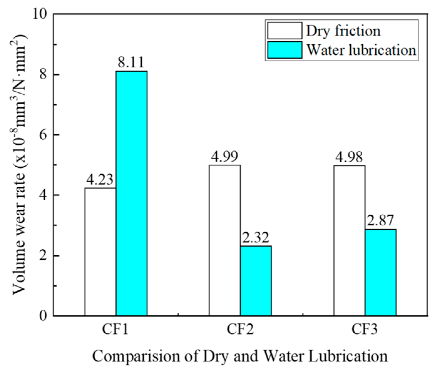
3.4. The Volume Wear Rate
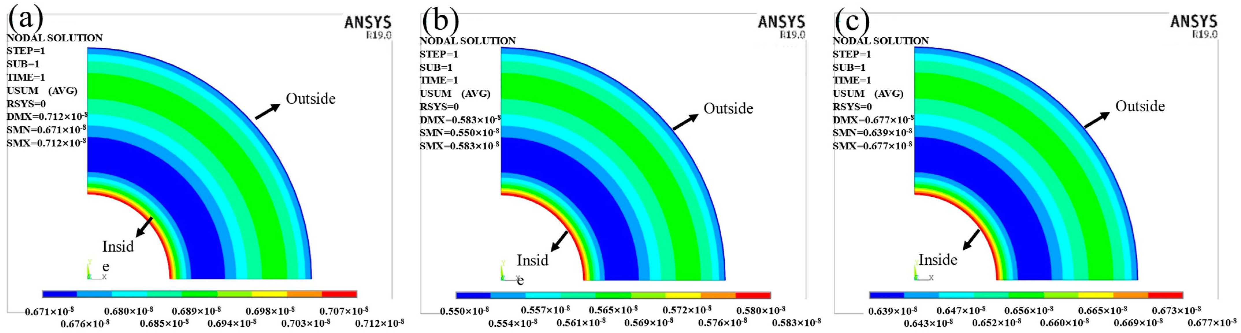
Figure 9 shows the three-dimensional morphology of the three specimens after wear under dry friction conditions, and the peaks appear on the surface of the specimens under dry friction conditions. CF1 shows a transition from a smooth surface to a peaked surface, with uneven distribution of surface abrasion marks and peaks concentrated on one side, as shown in Figure 10a. On the surface of CF2 and CF3, the crest-like protrusions showed a regular distribution of squares, and the protrusions were mainly concentrated in the position of the longitudinal and transverse crosses of the twill carbon fibers, as shown in Figure 9b,c. This is because the wear process raises the surface temperature of the contact surface under dry friction conditions. Subsequently, the surface material of CFHRP is prone to plastic deformation, which further softens the matrix [26], leading to an increase in the wear area of CF1. During the friction process, due to the accumulation of a large amount of debris, irregular mountain-like protrusions appear on the surface of CF1. CF2 and CF3 form regular peak-like protrusions due to the toughening effect of micron alumina [27], which makes the carbon fibers less susceptible to direct tearing.
Figure 10 shows the three-dimensional morphology of the three specimens after wearing under water-lubricated conditions. The surface of the specimens under water-lubricated conditions all showed the phenomenon of plow grooves, and the area of the crest-like protrusion structure increased. CF1 showed small grooves along the friction direction, and the crest-like protrusions were not concentrated on one side, but were evenly distributed, as shown in Figure 10a. In contrast, CF2 and CF3 peak-like protrusions were still squarely distributed, and the number of such peak-like protrusions formed after wear without flaking increased compared to the dry friction condition. A large number of crested protrusions can be seen in the linear and lamellar wear areas on the contact surface in the friction direction, and these protrusions bear the main load during the friction process. The peaks of CF1 are smaller and sparser than those of CF2 and CF3, which indicates that CF2 and CF3 have better anti-wear and drag reduction properties. This case was similarly found in the references [20,28,29].
After the statistics, it can be seen from Figure 11 that the volumetric wear rate of the three specimens under dry friction conditions is ranked as δCF2 > δCF3 > δCF1, but the wear amount of the three is not much different. Under the condition of water lubrication, the volume wear rate of the three specimens is δCF1 > δCF3 > δCF2, and the volume wear rate of CF1 is significantly higher than that of CF2 and CF3.
The volume wear rates of both CF2 and CF3 are smaller than the dry friction conditions under water-lubricated conditions [30], while the volume wear rate of CF1 is the opposite. This is because CF1 has a self-lubricating effect on carbon fiber itself under dry friction conditions, and the broken carbon fiber acts as a solid lubricant during the friction process, thus reducing the friction effect. However, under water-lubricated conditions, the carbon fiber particles produced by friction are washed away by the water flow during the grinding process, and there is no agglomeration. Although water also has a lubricating effect, it is weaker than the self-lubricating effect of carbon fiber, and the broken carbon fiber is insoluble in water, thus having a cutting effect on the friction surface under the water washout. The friction surface has a cutting effect, which increases the volume wear rate of the specimen, so the volume wear rate of CF1 increases under the condition of friction with water lubrication than under the condition of dry friction. CF2 and CF3 are due to the better heat resistance and hardness of micro-Al2O3 under dry friction conditions, resulting in the gathering of heat during the friction of the friction surface of the specimen to soften the surface of the friction surface, and as the friction proceeds, the carbon fiber is further broken off, and the micro-Al2O3 particles dispersed in the exposed composite material play a plowing role on the material surface so that the volume wear rate of CF2 and CF3 increased. Under the condition of water-lubricated friction, the flow of the water carried away the heat generated during friction and removed the abrasive debris from the friction area, preventing the accumulation of abrasive debris on the surface of the friction substrate, thus reducing the volumetric wear rate of carbon fiber composites. In addition, the cooling and lubricating effect of the water medium reduces the temperature of the contact area, which further inhibits the adhesive wear of the CFHRP. The micro-Al2O3 embedded in the carbon fiber surface enhanced the toughness of the composite and prevented it from being torn directly during wear, thus playing a role in reducing friction and wear [31], which reduced the wear of CF2 and CF3, and the volume wear rate of CF2 was smaller than that of CF3 under water-lubricated conditions, which was due to the strengthening effect of micro-Al2O3 on the composite with the added mass fraction. This is consistent with the study of Bingli, Fan et al. [27], so the volume wear rate of CF2 and CF3 under water-lubricated conditions is less than that under dry friction conditions [32].

3.5. Simulation

To investigate the influence of radial inertia load on frictional wear during the rotation of CFHRP, a simplified model of the grinding process was established, and the stress distribution and radial deformation of CFHRP in the grinding process were simulated using mechanical APDL analysis software in ANSYS.

3.5.1. Model Establishment

Through the analysis of the actual grinding surface, the grinding surface entity is a spatial axisymmetric problem. Because the carbon fiber plate thickness is thin and the forces are in a plane, all radial inertia load and the same radius inertia load size are equal, so the model can be simplified to an asymmetric plane stress analysis problem. The plane stress problem of the circular surface is an axisymmetric plane, and the model can be established to take its 1/4 circle for simulation.

3.5.2. The Setting of Simulation Conditions

The CFHRP is fixed on the rotating platform during the test, so the vertical load can be considered uniformly distributed in the plane of the counter-grinding ring during the rotation process, and its rotating angular speed is 84 rad/s (100 r/min). The elastic modulus of the three specimens is shown in Table 4, Poisson’s ratio is 0.3, the inner diameter of the ring is 5 mm, and the outer diameter is 15 mm.
Figure 12 shows the displacement contour cloud of the nodes of carbon fiber plate under the influence of radial load. As shown in the figure, the maximum deformation area is mainly concentrated near the inner circle. The maximum and minimum displacement deformation of each specimen are shown in Table 5, so the displacement deformation of the three specimens is ordered as CF2 < CF3 < CF1 and the nodal variation interval of CF1 is the largest, while the nodal variation interval of CF2 is the smallest, which indicates that the distribution of deformation on the same area CF2 and CF3 are more uniform than CF1. This is related to the tensile strength [24] and elastic modulus [33] of the specimens, while the mass fraction of micron-Al2O3 added directly affects the mechanical properties of the specimens [34,35].

4. Conclusions

In summary, the mechanical properties and wear resistance of carbon fiber hybrid-reinforced composites (CFHRP) with the addition of micrometer Al2O3 have been improved. According to the experimental results and analysis under dry and aqueous friction conditions, it can be concluded that under aqueous conditions, the addition of 6% micrometer Al2O3 has the best effect on increasing friction and reducing wear. The friction coefficient is CF2 < CF3 < CF1, and the volume wear rate is: δCF1 > δCF2 > δCF3. Under dry friction conditions, the friction coefficient was CF1≈CF2≈CF3 and the volumetric wear rate was δCF2 > δCF3 > δCF1. Under different elastic moduli, the deformation of the three samples was DMAXCF2 < DMAXCF3 < DMAXCF1. Therefore, the addition of micrometer Al2O3 under water-containing conditions has a prominent effect on increasing friction and reducing the wear of CFHRP.

Author Contributions

Conceptualization, W.C. and L.Z.; methodology, L.Z.; software, L.Z.; validation, L.Z., Z.W., Y.M. and W.C.; formal analysis, X.H.; investigation, L.Z.; resources, Y.B.; data curation, W.G.; writing—original draft preparation, L.Z.; writing—review and editing, W.C.; visualization, H.Y.; supervision, Y.B.; project administration, W.C.; funding acquisition, W.C. All authors have read and agreed to the published version of the manuscript.

Funding

This work was financially supported by Academician Dongyang Li Workstation in Yunnan Province (202305AF150019), Yunnan Provincial Agricultural Joint Special Key Project (202301BD070001-001), Yunnan Agricultural Joint Special General Project (202101BD070001-051), National Natural Science Foundation of China (No. 51865053).

Institutional Review Board Statement

Not applicable.

Informed Consent Statement

Written informed consent has been obtained from the patient(s) to publish this paper.

Data Availability Statement

The data that support the findings of this study are available on request from the corresponding author, [Chen], upon reasonable request.

Conflicts of Interest

The authors declare that they have no known competing financial interests or personal relationships that could have appeared to influence the work reported in this paper.

References

  1. Outirba, B.; Hendrick, P. Experimental characterization of friction and heat generation of carbon fibre brush seals for aero-engines. Tribol. Int. 2020, 151, 106448. [Google Scholar] [CrossRef]
  2. Sudhin, A.; Remanan, M.; Ajeesh, G.; Jayanarayanan, K. Comparison of Properties of Carbon Fiber Reinforced Thermoplastic and Thermosetting Composites for Aerospace Applications. Mater. Today Proc. 2020, 24, 453–462. [Google Scholar] [CrossRef]
  3. Soutis, C. Carbon fiber reinforced plastics in aircraft construction. Mater. Sci. Eng. A 2005, 412, 171–176. [Google Scholar] [CrossRef]
  4. Yadvinder, S.; Jujhar, S.; Shubham, S.; Lam, T.D.; Nguyen, D.N. Fabrication and characterization of coir/carbon-fiber reinforced epoxy based hybrid composite for helmet shells and sports-good applications: Influence of fiber surface modifications on the mechanical, thermal and morphological properties. J. Mater. Res. Technol. 2020, 9, 15593–15603. [Google Scholar]
  5. Sreejith, M.; Rajeev, R.S. 25—Fiber reinforced composites for aerospace and sports applications. In Fiber Reinforced Composites; Joseph, K., Oksman, K., George, G., Wilson, R., Appukuttan, S., Eds.; Woodhead Publishing: Sawston, UK, 2021; pp. 821–859. [Google Scholar]
  6. Ali, H.T.; Akrami, R.; Fotouhi, S.; Bodaghi, M.; Saeedifar, M.; Yusuf, M.; Fotouhi, M. Fiber reinforced polymer composites in bridge industry. Structures 2021, 30, 774–785. [Google Scholar] [CrossRef]
  7. Jiang, X.; Kolstein, H.; Bijlaard, F.S.K. Moisture diffusion and hygrothermal aging in pultruded fibre reinforced polymer composites of bridge decks. Mater. Des. 2012, 37, 304–312. [Google Scholar] [CrossRef]
  8. Mei, K.; Li, Y.; Lu, Z. Application study on the first cable-stayed bridge with CFRP cables in China. J. Traffic Transp. Eng. (Engl. Ed.) 2015, 2, 242–248. [Google Scholar] [CrossRef] [Green Version]
  9. Zhang, Y.; Tabandeh, A.; Ma, Y.; Gardoni, P. Seismic performance of precast segmental bridge columns repaired with CFRP wraps. Compos. Struct. 2020, 243, 112218. [Google Scholar] [CrossRef]
  10. Jia, J.; Zhao, L.; Wu, S.; Wang, X.; Bai, Y.; Wei, Y. Experimental investigation on the seismic performance of low-level corroded and retrofitted reinforced concrete bridge columns with CFRP fabric. Eng. Struct. 2020, 209, 110225. [Google Scholar] [CrossRef]
  11. Ye, H.; Wu, C.; Liu, D.; Wang, T.; Zhang, Q. Friction and wear behavior of CFRP plate in contact with roughened mould steel under high normal pressure. Constr. Build. Mater. 2019, 220, 308–319. [Google Scholar] [CrossRef]
  12. Yogesh, S.; Madhu, S. Comparative study of wear and friction behavior of CFRP/AL composite laminate under dry condition. Mater. Today Proc. 2020, 33, 716–719. [Google Scholar] [CrossRef]
  13. Jia, J.; Chen, J.; Zhou, H.; Hu, L.; Chen, L. Comparative investigation on the wear and transfer behaviors of carbon fiber reinforced polymer composites under dry sliding and water lubrication. Compos. Sci. Technol. 2004, 65, 1139–1147. [Google Scholar] [CrossRef]
  14. Österle, W.; Dmitriev, A.I.; Wetzel, B.; Zhang, G.; Häusler, I.; Jim, B.C. The role of carbon fibers and silica nanoparticles on friction and wear reduction of an advanced polymer matrix composite. Mater. Des. 2016, 93, 474–484. [Google Scholar] [CrossRef]
  15. Wang, Z.; Huang, X.; Bai, L.; Du, R.; Liu, Y.; Zhang, Y.; Zhao, G. Effect of micro-Al2O3 contents on mechanical property of carbon fiber reinforced epoxy matrix composites. Compos. Part B Eng. 2016, 91, 392–398. [Google Scholar] [CrossRef]
  16. Du, J.; Liu, Y.-H.; Yu, S.-Y.; Li, W.F. Dry sliding friction and wear properties of Al2O3 and carbon short fibres reinforced Al–12Si alloy hybrid composites. Wear 2004, 257, 930–940. [Google Scholar]
  17. Poodts, E.; Minak, G.; Mazzocchetti, L.; Giorgini, L. Fabrication, process simulation and testing of a thick CFRP component using the RTM process. Compos. Part B Eng. 2014, 56, 673–680. [Google Scholar] [CrossRef]
  18. Vita, A.; Castorani, V.; Germani, M.; Marconi, M. Comparative life cycle assessment of low-pressure RTM, compression RTM and high-pressure RTM manufacturing processes to produce CFRP car hoods. Procedia CIRP 2019, 80, 352–357. [Google Scholar] [CrossRef]
  19. Jing, P.; Wang, H.; Chen, W.; Chen, L.; Yin, H.; Wu, H.; Li, D. Effect of Ti addition on microstructure and tribological properties of laser cladding Ni35/WC coating in an oxygen-free environment. Surf. Coat. Technol. 2022, 440, 128480. [Google Scholar] [CrossRef]
  20. Chen, B.; Wang, J.; Yan, F. Comparative investigation on the tribological behaviors of CF/PEEK composites under sea water lubrication. Tribol. Int. 2012, 52, 170–177. [Google Scholar] [CrossRef]
  21. Wang, Z.; Gao, D. Friction and wear properties of stainless steel sliding against polyetheretherketone and carbon-fiber-reinforced polyetheretherketone under natural seawater lubrication. Mater. Des. 2014, 53, 881–887. [Google Scholar] [CrossRef]
  22. Ren, J.; Chen, H.; Ma, B.; Zhao, F.; Wang, C.; Hong, H.; Li, Y.; He, X.; Chen, X.; An, R. Tribological performance of in-situ transformed Cf/Al2O3 self-lubricating composite. Wear 2017, 376–377, 363–371. [Google Scholar] [CrossRef]
  23. Guan, Z.; Wu, D.; Cheng, Q.; Wang, Z.; Tang, M.; Liu, Y. Friction and Wear characteristics of CF/PEEK against 431 stainless steel under high hydrostatic pressure water lubrication. Mater. Des. 2020, 196, 109057. [Google Scholar] [CrossRef]
  24. Chen, B.; Li, X.; Jia, Y.; Li, X.; Yang, J.; Yan, F.; Li, C. MoS2 nanosheets-decorated carbon fiber hybrid for improving the friction and wear properties of polyimide composite. Compos. Part A Appl. Sci. Manuf. 2018, 109, 232–238. [Google Scholar] [CrossRef]
  25. Johansson, P.; Marklund, P.; Björling, M.; Shi, Y. Effect of humidity and counterface material on the friction and wear of carbon fiber reinforced PTFE composites. Tribol. Int. 2021, 157, 106869. [Google Scholar] [CrossRef]
  26. Unal, H.; Kurtulus, E.; Mimaroglu, A.; Aydin, M. Tribological Performance of PTFE Bronze Filled Composites under Wide Range of Application Conditions. J. Reinf. Plast. Compos. 2010, 29, 2184–2191. [Google Scholar] [CrossRef]
  27. Bingli, F.; Dalei, Z.; Yulin, Y. Tribological properties of hybrid Kevlar/PTFE fabric reinforced phenolic composite filled with nano-alumina. In Proceedings of the 2010 International Conference on Mechanic Automation and Control Engineering, Wuhan, China, 26–28 June 2010; pp. 457–460. [Google Scholar]
  28. Xie, G.Y.; Sui, G.X.; Yang, R. Effects of potassium titanate whiskers and carbon fibers on the wear behavior of polyetheretherketone composite under water lubricated condition. Compos. Sci. Technol. 2011, 71, 828–835. [Google Scholar] [CrossRef]
  29. Wang, J.; Gu, M. Wear properties and mechanisms of nylon and carbon-fiber-reinforced nylon in dry and wet conditions. J. Appl. Polym. Sci. 2004, 93, 789–795. [Google Scholar] [CrossRef]
  30. Chen, J.D.; Chern Lin, J.H.; Ju, C.P. Effect of humidity on the tribological behavior of carbon-carbon composites. Wear 1996, 193, 38–47. [Google Scholar] [CrossRef]
  31. Zhang, X. Study on the Tribological Properties of Carbon Fabric Reinforced Phenolic Composites Filled with Nano-Al2O3. Journal of macromolecular science. Physics 2017, 56, 568–577. [Google Scholar]
  32. Ye, H.; Zhang, Q.; Liu, C.; Wu, C.; Duan, Z. Failure mechanisms governing anchoring force of friction-based wedge anchorage for prestressed CFRP plate. Compos. Struct. 2019, 225, 111142. [Google Scholar] [CrossRef]
  33. Duan, S.; Iyer, A.H.; Carlstedt, D.; Rittweger, F.; Sharits, A.; Maddox, C.; Riemschneider, K.R.; Mollenhauer, D.; Colliander, M.; Liu, F.; et al. Effect of lithiation on the elastic moduli of carbon fibres. Carbon 2021, 185, 234–241. [Google Scholar] [CrossRef]
  34. Hussain, M.; Nakahira, A.; Niihara, K. Mechanical property improvement of carbon fiber reinforced epoxy composites by Al2O3 filler dispersion. Mater. Lett. 1996, 26, 185–191. [Google Scholar] [CrossRef]
  35. Zhu, C.; Su, Y.; Zhang, D.; Ouyang, Q. Effect of Al2O3 coating thickness on microstructural characterization and mechanical properties of continuous carbon fiber reinforced aluminum matrix composites. Mater. Sci. Eng. A Struct. Mater. Prop. Microstruct. Process. 2020, 793, 139839. [Google Scholar] [CrossRef]
Figure 1. SEM image of Micro-Al2O3 powder.
Coatings 13 01227 g001
Figure 2. Schematic diagram of the vacuum-assisted resin transfer molding process.
Coatings 13 01227 g002
Figure 3. Schematic diagram of pin disc continuous friction.
Coatings 13 01227 g003
Figure 4. Clamping of the sample (a) upper; (b) lower.
Coatings 13 01227 g004
Figure 5. X-ray diffraction pattern of carbon fiberboard.
Coatings 13 01227 g005
Figure 6. Friction coefficient of three samples under different lubrication conditions: (a). Dry friction condition. (b). Water lubrication condition.
Coatings 13 01227 g006
Figure 7. Surface morphology of three samples after wear under dry friction conditions: (a) Sample CF1, (b) Sample CF2, (c) Sample CF3.
Coatings 13 01227 g007
Figure 8. Surface morphology of three samples after wearing underwater lubrication: (a) Sample CF1, (b) Sample CF2, (c) Sample CF3.
Coatings 13 01227 g008
Figure 9. Three-dimensional morphology of three samples after wearing dry friction conditions: (a) Sample CF1, (b) Sample CF2, (c) Sample CF3.
Coatings 13 01227 g009
Figure 10. Three-dimensional morphology of three samples after wearing underwater lubrication: (a) Sample CF1, (b) Sample CF2, (c) Sample CF3.
Coatings 13 01227 g010
Figure 11. Comparison of volumetric wear rates of three samples under dry friction and water lubrication.
Coatings 13 01227 g011
Figure 12. Cloud diagram of displacement isoline: (a) CF1, (b) CF2, (c) CF3.
Coatings 13 01227 g012
Table 1. Performance parameters of carbon fiber for the experiment.
TowTensile StrengthElastic ModulusDensityDiameter
12 K4 GPa240 GPa1.8 g/cm37 μm
Table 2. Mass fraction of Al2O3 added to three samples (wt%).
SampleCF1CF2CF3
Al2O3 06%1%
Table 3. Chemical composition of the GCr15 steel ring.
Chemical Composition (wt.%)
CSiMnCrMo
0.95~1.050.15~0.350.25~0.451.4~1.65≤0.1
Table 4. Elastic modulus of the sample (MPa).
SampleCF1CF2CF3
Elastic modulus (E)1.18 × 1051.44 × 1051.24 × 105
Table 5. Node displacement variation of three samples (10–8 mm).
CF1CF2CF3
DMAX0.7120.5830.677
DMIN0.6710.5500.639
ΔMax–Min0.0950.0330.038
Disclaimer/Publisher’s Note: The statements, opinions and data contained in all publications are solely those of the individual author(s) and contributor(s) and not of MDPI and/or the editor(s). MDPI and/or the editor(s) disclaim responsibility for any injury to people or property resulting from any ideas, methods, instructions or products referred to in the content.

