Article

A New Coated Proppant for Packing Fractures in Oil Reservoirs

1
School of Petro-Gas Engineering, Liaoning Petrochemical University, Fushun 113001, China
2
Geological Research Institute of Daqing Oilfield No.1 Production Plant, Daqing 163318, China
3
Petro China Tarim Oilfield Company, Talimu 843300, China
*
Author to whom correspondence should be addressed.
Coatings 2023, 13(7), 1238; https://doi.org/10.3390/coatings13071238
Submission received: 25 June 2023 / Revised: 6 July 2023 / Accepted: 6 July 2023 / Published: 11 July 2023

Abstract

:
The method of packing conventional proppant into fractures is used to maintain high liquid permeability. In this study, by coating a hydrophobic material on the surface of a proppant, the layer packed with this coated proppant was endowed with water-plugging and oil-permeability capacities. Moreover, several research experiments were carried out to verify the proposed method: a water plugging capacity (WPC) test of the coated proppant layer, compression and temperature resistance tests of the coated proppant (temperature range from 90 to 210 °C; pressure range from 5.9 to 91.4 MPa), and a 3D test of the oil recovery enhancement. The results show that the proppant coating has good compression resistance, and the proppant begins to break at 27.3 MPa. The upper limit of the temperature resistance of the coating is 170 °C. The WPC of the layer packed with coated proppant was still reliable during fracture, which was enhanced by at least 20% compared with that of the layer packed with a conventional proppant. The fracture packed with the coated proppant had superior working performance compared with that packed with a conventional proppant. It can reduce the flow capacity of the water phase breaking into the dominant flow passage so as to delay the rise in the water production of the oil well and prolong the duration of oil production. In this way, oil recovery could be increased by about 7.7%. In conclusion, the technology proposed in this paper has particular water-plugging and oil-permeating characteristics, with remarkable technical advantages, thus providing a new idea for the development of water control in fracture reservoirs.

1. Introduction

Hydraulic fracturing can significantly enhance oil recovery [1]. However, long fractures bring about production challenges and are usually affected adversely by water breakthrough [2]. Once the water breaks into the fracture, the water cut rises rapidly, the oil production efficiency decreases sharply, the life of the oil well is severely shortened, and the overall swept volume of the oil reservoir reduces [3]. Some of the methods for addressing the problem of water breakthrough are as follows:
(1)
The time of water breakthrough can be delayed by perforating wellbores with variable densities [4,5]. This is based on the throttling principle to balance the flow quantities of different layers.
(2)
People also use inflow control devices (ICDs) to control water production and to equalize the oil influx of each part of horizontal wellbores [6,7,8,9].
(3)
Some scholars have studied tertiary oil recovery technology. Polymer flooding, surfactant flooding, and ultrasonic waves flooding are adopted to control water breakthrough and enhance oil recovery [10,11,12,13].
These technologies have been applied to main reservoirs in oil fields and achieved good results. However, from the perspective of water control, technologies (1) and (3) can only control the water flow before water breakthrough, and the water eventually breaks into the oil well. In contrast, technology (2) can control the water when it breaks into the bottom of the well. However, ICD technology is generally used for horizontal wells or wells with multiple layers for combined production, and the cost is high. Therefore, for controlling water coning and increasing the production of oil wells, this paper proposes a technology of packing fractures with a coated proppant, which has water-plugging and oil-permeating capacities. As a source of inspiration, the superhydrophobic surfaces of lotus leaves aroused great interest in our research [14,15], which possess potential in water-plugging and oil-permeability applications. Another source of inspiration was superhydrophobic surfaces, which show extremely good effects in some applications, for example, self-cleaning [16], anti-corrosion [17], and oil-water separation [18] applications. It showed us that a superhydrophobic surface could be designed for coating a proppant and fabricating an appropriate rough proppant surface in terms of hierarchical nano/microstructures and introducing low-surface-energy materials [19,20]. To date, various technologies of coating have been reported, including thermal spray [21], sol-gel dip coating [22], electrostatic painting [23], chemical etching [24], solution immersion [25], etc. However, for artificial coatings that provide super hydrophobicity effects, one of the biggest problems is their low compression resistance and temperature stability due to the easily damaged microstructures [26,27]. This greatly limits their practical application. In addition, coating technologies are rarely applied for proppants except when coating proppants to adjust density to enhance suspension ability [28,29,30] or thermally fixing the proppant in a hydraulic fracturing crack in order to limit the removal of the proppant from the well during production. Additionally, few existing studies have focused on using superhydrophobic-coated proppants in fractures with excellent compression resistance and temperature stability to achieve water plugging and oil permeability in fractures. Compared with conventional proppants, this coated proppant has apparent advantages.
Several strategies have been applied to improve the behavior of superhydrophobic coatings, such as adding styrene-butadiene rubber and polydopamine in the coatings [31], endowing the ceramic coating with hydrophilic polylithium and nano-sized Al2O3 power [32], and introducing carbon nanotube (CNT) composite material to obtain high mechanical strength [33]. Despite the significant progress noted above, challenges still remain in developing superhydrophobic coatings with high compression resistance and temperature stability to accommodate real environmental conditions.
In this study, a superhydrophobic coating was fabricated onto a proppant surface based on an epoxy solution using a simple and versatile two-step dip-coating method. The conventional proppant was hydrophobicated via the chemical etching of the surfaces and then coated with a low-surface-energy material, APDMS. The introduction of APDMS also provided an epoxy matrix to enhance the stability of the coating. Moreover, the epoxy solution could also be employed as the binder between the coating and micro/nano-SO2 through the curing process. In addition, considering the science and practicality of water control in fractures under a particular high-pressure and -temperature environment, we carried out compression resistance, temperature resistance, and water plugging capacity (WPC) tests with the coated proppant. Then, we conducted experiments using a large-scale simulation device for the development of a 3D oil reservoir to compare the development effects between fractures packed with a conventional proppant and those packed with the coated proppant, aiming to provide a new idea for water control in the development of oil reservoirs with artificial hydraulic fracturing.

2. Experimental Section

2.1. Materials

Selected Lanzhou quartz sand was used as a conventional proppant (density:1400 kg/m3, mesh count: 40, Tonghua Daquan Gravel Co., Ltd., Tonghua, China). Ethyl acetate (EA) and alcohol (purity 99.8 wt%) solvents were supplied by Shenyang Tiangang Chemical Co., Ltd., Shenyang, China. Hydrophobic SiO2 nanoparticles (average diameter: 40 nm); rubber powders (average diameter: 40 nm); bisphenol A epoxy resin (Epoxy E44) and curing agent (triethylene tetramine) were supplied by Fushun Chemical Co., Ltd., Fushun, China. NaOH (purity 96 wt%), amino silicone oil (APDMS, purity 99.8 wt%), and poly-uoroalkoxy (PFA) were provided by Dupont, Wilmington, DE, USA.

2.2. Preparation of Tyzs-40-Coated Proppant

Chemical etching of proppant: Pristine proppant was first cleaned with deionized water and anhydrous ethanol to remove the impurities and dried at 90 °C. Then, the cleaned proppant was treated with a sodium hydroxide solution (100 g L−1) at 100 °C for 20 min, washed with abundant water until the pH value of the proppant surfaces reached 7, and finally dried at 90 °C in an oven.
Hydrophobization of etched proppant: A total of 0.5 g of APDMS was dissolved in 10 mL of ethyl acetate and ultrasonicated for 20 min. Subsequently, the etched proppant was dipped into the as-prepared solution at 60 °C for 30 min and dried at 90 °C for 1 h. The APDMS-coated proppant was superhydrophobic and denoted as Z-proppant.
Preparation of superhydrophobic coating: The superhydrophobic coating was prepared via the rapid solution immersion method. Firstly, 10 g of epoxy E44 was dissolved into a certain amount of ethyl acetate solution; then, 3 g of PFA and 3% hydrophobic SiO2 nanoparticles were added into the mixture and under ultrasonic oscillation for 1 h. In order to improve the abrasion resistance, 19% rubber powders was added, and then ultrasonic oscillation was repeated for 20 min. Subsequently, the Z-proppant was immersed into the prepared epoxy resin solution for 3 min. Finally, the coating of the proppant was cured at 90 °C for 3 h. The curing reaction of epoxy resin and amine curing agent occurred based on the chemical bonding connection between the epoxy group and amino group, and then the achievement of proppant coating was indicated by its transformation into black particles with high sphericity. The cost of this coated proppant is about 310 USD/m3, which is a very reasonable cost for use to develop any oil field. Additionally, the molecular structures of some of the chemicals used in this work and the complete process of fabricating the sample are shown in Figure 1.

2.3. Tests of FT-IR Spectra

The compositions of the pristine and coated proppant were all characterized with a Tensor 27 infrared spectrometer (FT-IR). The test steps were as follows: (1) start up Tensor 27 infrared spectrometer and preheat for 20 min; (2) prepare coated proppant and uncoated proppant compression sample 1 and sample 2, paying attention to ensure the uniformity of the samples; (3) collect the background, then place the prepared samples and test the infrared spectra of sample 1 and sample 2, separately; (4) map peak labeling and save the detection report.

2.4. Tests of Compression Resistance, Temperature Resistance, Surface Wettability, and Water Plugging Capacity (WPC)

2.4.1. Test of Compression Resistance, Temperature Resistance, and Surface Wettability

The objective of this experiment was to determine the limitation of the coated proppant regarding safety because the water-plugging capacity of the coated proppant depends on the superhydrophobic performance of the surface coating on the proppant. Under the special working conditions of oil reservoir development, when a proppant is filled in a fracture, the fracture closure pressure and oil body temperature are very high. Therefore, it was necessary to conduct relevant tests to confirm whether the surface coating of the proppant is reliable.
A particle strength tester (Jiangsu Haian Co., Ltd., Suzhou, China) was used to measure the compressive strength of a layer packed with coated proppant at 5.9, 23.7, and 91.4 MPa, separately. The scientific reason for choosing these pressures was because of the relationship between reservoir depth and fracture closure pressure; the relationship between pressure gradient and reservoir depth is about 1.0 MPa/100 m in oil fields in China. The average fracture closure pressure is shown in Table 1.
A constant-temperature box (Jiangsu Huada Co., Ltd., Changzhou, China) was used to measure the temperature resistance of the coated proppant at 120, 170, and 210 °C, separately. The scientific reason for choosing these temperatures was because we needed know the upper temperature limit of the coating. So, the temperature setting was gradually increased from coating preparation temperature of 90 °C. The operation of this test was very simple: we only needed to place the coated proppant into the prepared constant-temperature box at the corresponding temperature conditions and let it sit for 180 days. Then, the surface morphology of the coated gravel was observed using a Tecnai G2 F20 S-TWIN field-emission transmission electron microscope (FEI Company, Hillsboro, OR, USA). The purpose was to find the coating failure window as influenced by temperature.
A contact angle measuring instrument (Hack Company in Kurtscheid, Germany) was used to measure the surface wettability of the coated proppant layer. The purpose of this test was to confirm the coating failure window under the influence of temperature and pressure. The test method steps were as follows: (1) take the coated proppant affected by different temperatures or pressures as a test sample; (2) stack the sample particles into a flat layer with a thickness of 0.5 cm; (3) drip water onto the surface of the sample particles layer; (4) directly measure the contact angle between the water droplets and the sample layer’s surface.

2.4.2. WPC Test

The actual WPC of a fracture layer packed with coated proppant was tested and compared with that of a fracture layer packed with conventional proppant under the same gas permeability conditions. In the test, the oil permeability of the layers packed with proppants was 3000 mD (1 mD = 10−3 μm2), and the differential pressure of water injection was between 0.2 and 6 MPa. The experimental flow chart is shown in Figure 2. The specific test steps were as follows: (1) put the conventional proppant (40 mesh) into a proppant pack device; (2) test the gas permeability of the gravel-packed model; (3) test the water permeability of the proppant-packed model for various pressures; (4) replace the conventional proppant with the coated proppant (here, it is necessary to adjust the packing method with the coated proppant continually until the gas permeability equals the gas permeability tested in step (2), then repeat the corresponding water permeability test; (5) after the WPC test, use the air flooding sample, open the sample valve, and let it stand at 90 °C to evaporate the remaining water; (6) test the oil flow quantity with different pressure differences.
The WPC of the proppant was tested. Both proppants had a thickness of 5 cm. The WPC of the packing layer was calculated by Formula (1):
WPC = | K con ,   i K coa ,   j | K con ,   i
where WPC is the WPC of the layer packed with coated proppant; K con ,   i is the water permeability of the layer packed with conventional proppant; K coa ,   j is the water permeability of the layer packed with coated proppant.

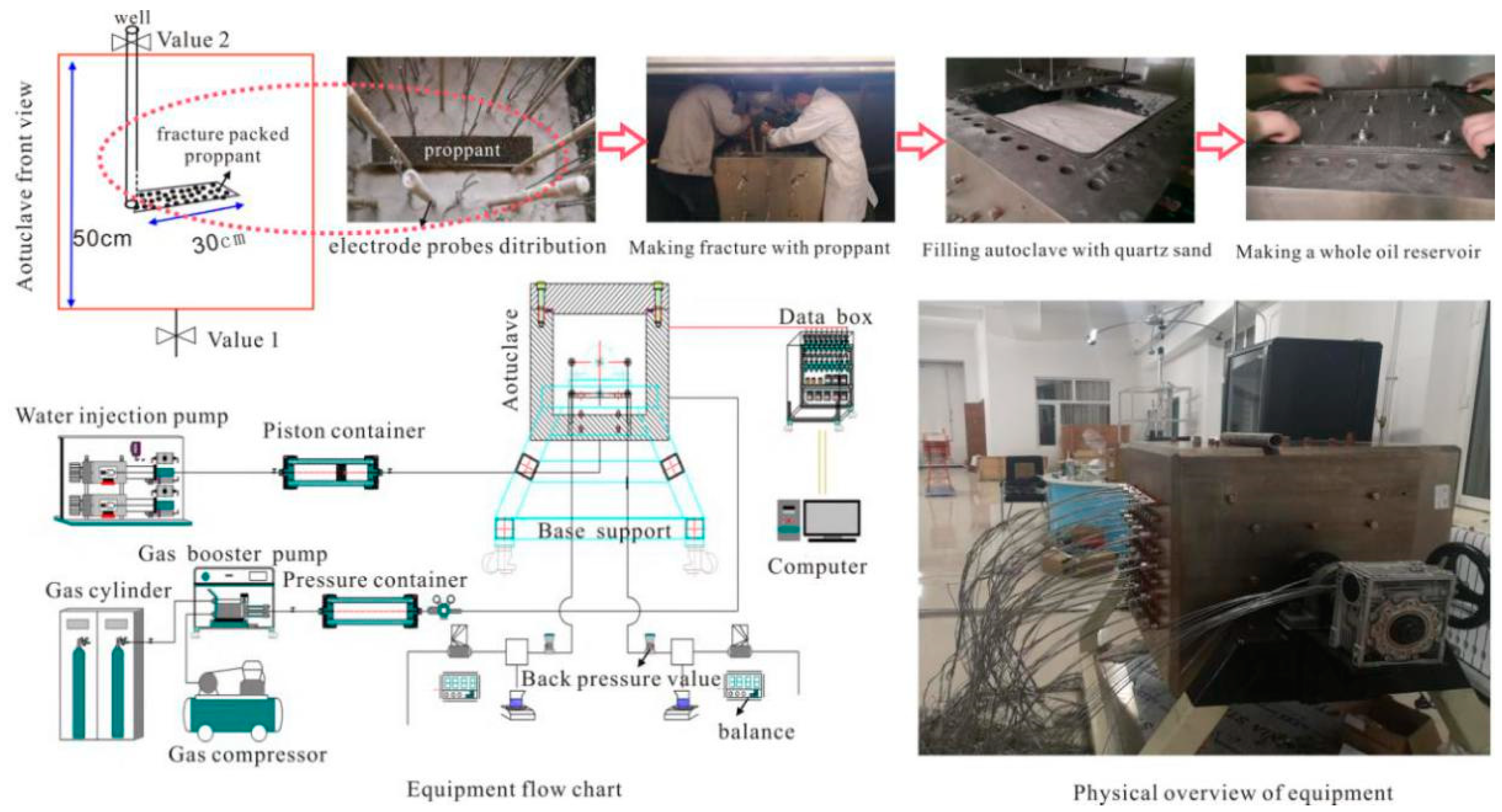
2.5. Test of Coated Proppant Application in 3D Oil Reservoir Development

As illustrated in Figure 3, a large-scale 3D experiment was carried out using resistivity probes to develop an oil reservoir. The size of the autoclave in this study was 50 cm × 50 cm × 50 cm (length, width, and height, respectively). The permeability of the layer packed with coated proppant was 3000 mD. There were 25 sets of electrode probes placed inside the autoclave. The water-plugging and production-increasing effects of the layer packed with coated proppant were evaluated by measuring the change in the water saturation field of the water-flooded oil reservoir during production. Based on the parameters of Well DQSL-II-142 (the well had a length of 300 m and a width of 200 m; the average porosity was 0.214; the fracture length was 30 m; and the oil production was 11.2 t/d), and according to oil field similarity criterion, simulation parameters were determined as follows: the length and the width of the fracture were 30 and 1 cm, respectively; the wellbore diameter was 6 mm; the packing thickness of the proppants was 1.4 cm; and the production pressure difference was 0.4 MPa.
The experimental steps were as follows: First, we surrounded the well (6 mm in diameter, with a hole density of 4 holes/cm) with conventional proppant (scheme 1) or coated proppant (scheme 2). Then, we filled the autoclave with quartz sand until the permeability of reservoir layer reached 3000 mD. Second, we opened the No.1 valve to inject water into the oil reservoir. The pore volume of the oil reservoir model was set to 44.65 L. The oil was injected through the No.1 valve and flowed out of the No.2 valve, so as to keep the bound water saturation of the oil reservoir model at 0.284. After 12 h, we opened the No.1 valve to inject water until the water cut reaches 98%. We recorded the gas and water production.

3. Results and Discussion
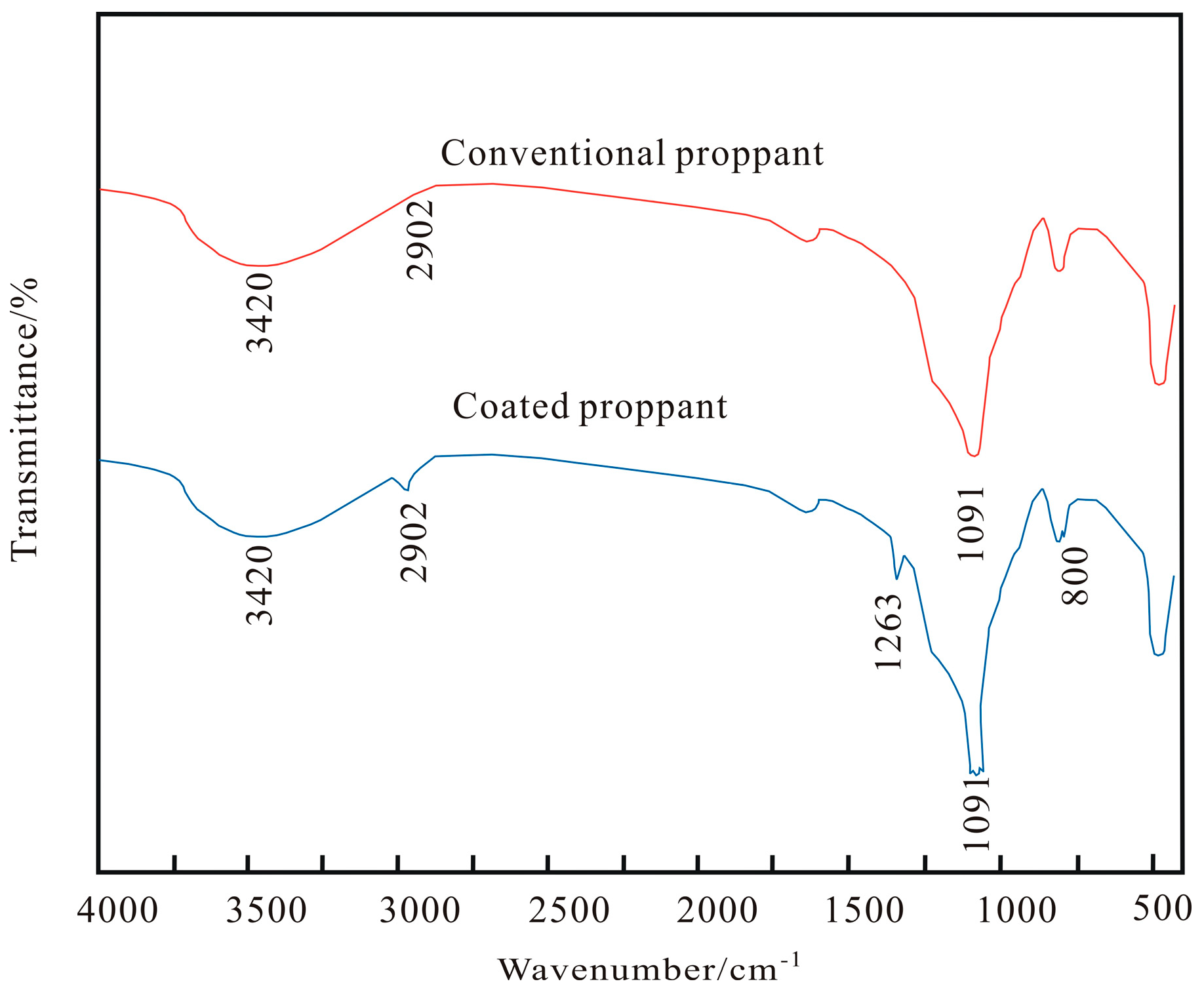
3.1. FT-IR Spectrum

In order to examine the change in the surface groups after surface hydrophobic treatments, the FT-IR spectra of the hydrophobic proppant were compared with those of the pristine one. The result is shown in Figure 4. After the hydrophobic treatment of the proppant, a new peak at 2902 cm−1 was observed, which we assigned to the C–H stretching vibration, and indicated the formation of epoxy resin coatings. In addition, the FT-IR spectrum of the hydrophobic coating presented characteristic absorptions around 1263 and 801 cm−1, corresponding to C–N stretching vibration and N–H deformation vibration. Amino silicone oil (APDMS) was coated onto the surface of the proppant, and the presence of amino groups may have underwent curing bonding with epoxy groups. Also, the spectrum of the coating proppant exhibited amplitude stretching and local fluctuations at 1091 cm−1; obviously, the total amount of Si–O–Si increased; then, combined with Figure 5e, we found that micro/nanosilica was successfully coated on the proppant.

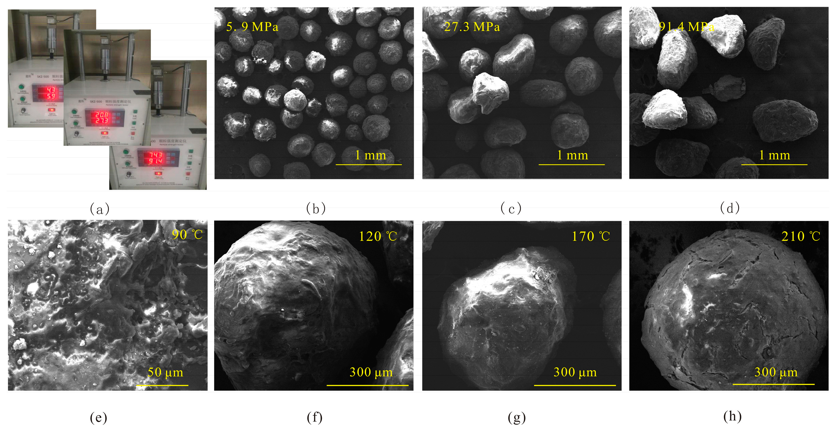
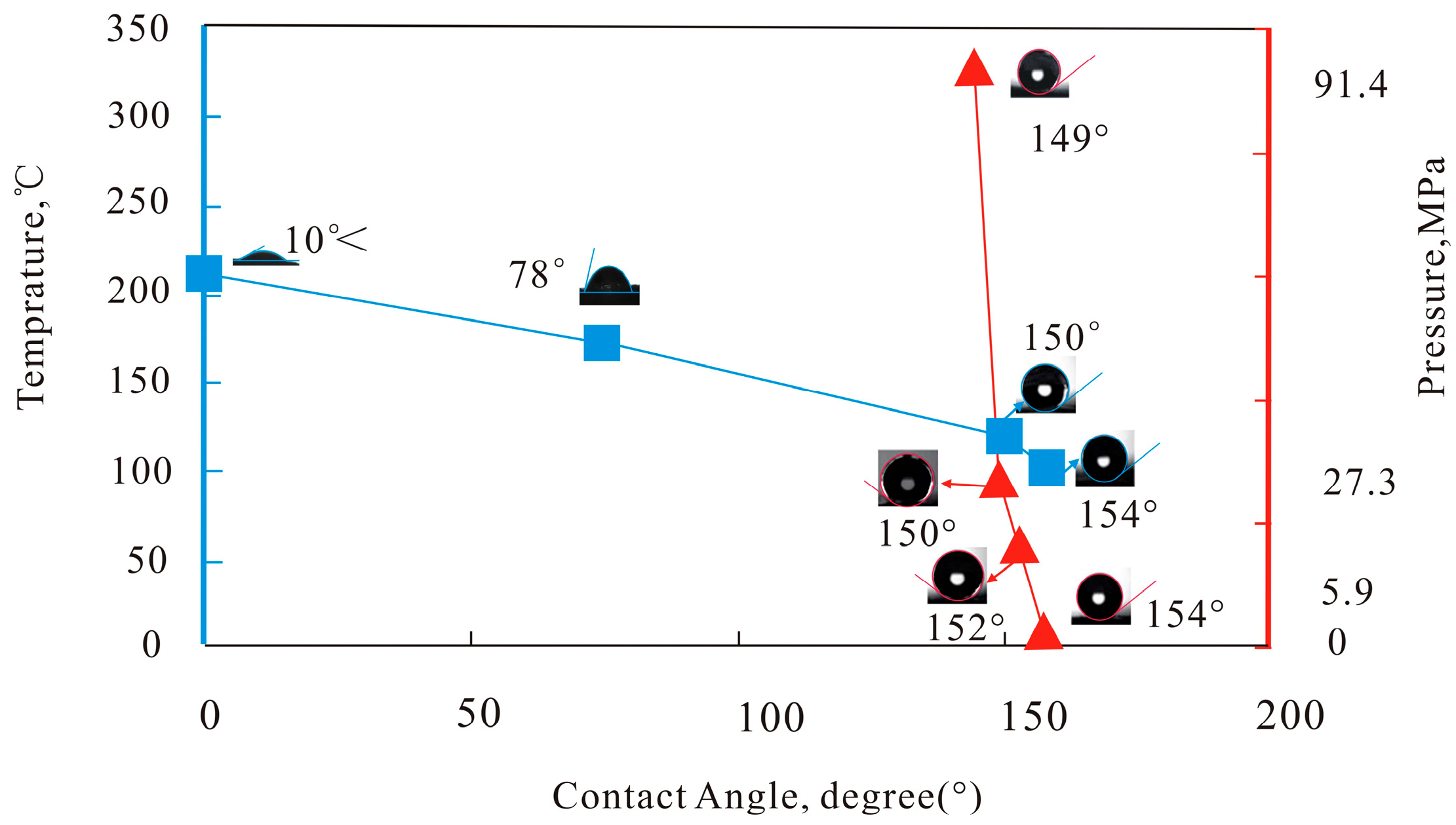
3.2. Morphology and Surface Wettability of Proppant Coating

Figure 5e displays the original surface microstructure of the coated proppant (magnified 1600 times), which has a micro/nanostructure with some spots in a concave–convex shape. These spots are micro/nanosilica. Figure 5b–d show that as the pressure increased, the shape of the proppant transformed from spheroid to elliptical. After the proppant is compressed and deformed, the fracture conductivity is affected. Additionally, the structure of the coated proppant did not change at a temperature of 90 °C, and the corresponding contact angle was larger than 154°, as shown in Figure 6.
Figure 5f and Figure 6 show that the surface structure of the coated proppant was still in good condition and remained superhydrophobic when the temperature was lower than 120 °C, and the contact angle was larger than 154°. In Figure 5g and Figure 6, when the temperature reaches 170 °C, the surface coating of the proppant is about to fracture, and the hydrophobic angle decreases to 78°. It is shown in Figure 5h and Figure 6 that when the temperature exceeded 210 °C, the surface coating was completely broken, and the hydrophobic angle was very small and could not be tested. This is because the covalent bond between the amine group of the surface coating and the epoxy group of the epoxy resin was damaged by high temperatures.

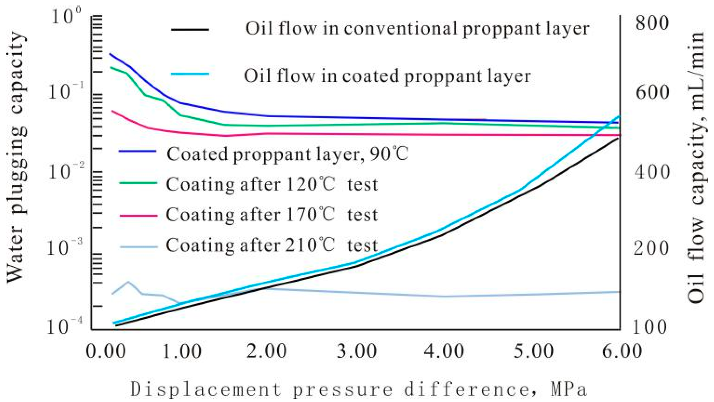
3.3. WPC of Coated Proppant Layer

The result in Figure 7 indicates that the property of the surface coating of the coated proppant was extremely stable, with excellent compression resistance. The WPC of the layer packed with coated proppant exceeded that of the layer packed with conventional proppant by more than 20%. The temperature resistance window of the coated proppant was between 170 and 210 °C, in which the WPC quickly fell. The results were the same as those for the surface morphology of the coating. The WPC of the layer packed with coated proppant was outstanding when the temperature was lower than 120 °C, exceeding that of the layer packed with conventional proppant by more than 20%, as the driving differential pressure was lower than 0.4 MPa. However, the WPC of the coated proppant was fully lost when the temperature was higher than 210 °C. At this temperature, the WPC of the layer packed with coated proppant exceeded that of the layer packed with conventional proppant by only 0.1%.
After the WPC test, the water in the proppants was dried with high-pressure air. Then, the oil flow experiment was conducted to determine the difference in the oil flow capacity between the layers packed with conventional proppant and those packed with coated proppant. The oil flow capacity of the layer packed with coated proppant exceeded that of the layer packed with conventional proppant by more than at least 5% under a pressure difference of 0.4 MPa (Figure 7). The oil flow capacity of the layer packed with coated proppant became stronger with the increase in differential pressure: when the differential pressure reached 6 MPa, the oil flow capacity of the layer packed with coated proppant exceeded that of the layer packed with conventional proppant by more than 10%.
As shown in Figure 8, the conventional proppant and coated proppant with a thickness of 0.5 cm were laid on a desktop, and water was dripped on them. Water droplets infiltrated into the layer packed with conventional proppant but stayed on the surface of the layer packed with coated proppant. This indicated that the layer packed with coated proppant had WPC. The WPC mechanism is the hydrophobic property of the coated proppant that causes water to be spherical on its surface, to retain a large diameter at the pore entrance, and to create additional flow resistance. In other words, the contact angle between the layer packed with coated proppant and the water was greater than 90°, indicating hydrophobicity, and the capillary force presented resistance. Meanwhile, the supporting resistance of water droplets increases as they squeeze into pores. The contact angle between the layer packed with conventional proppant and water was less than 90° (hydrophilic), and the capillary force presented a driving force. Therefore, the force analysis implied that the layer packed with coated proppant had additional water flow resistance compared with the layer packed with conventional proppant.

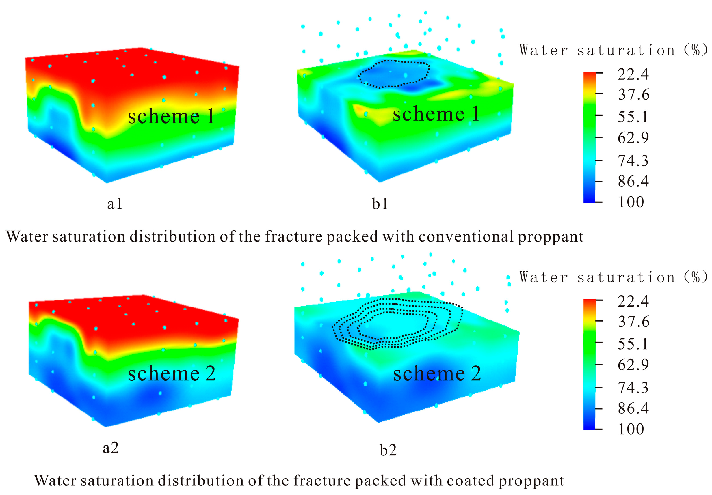
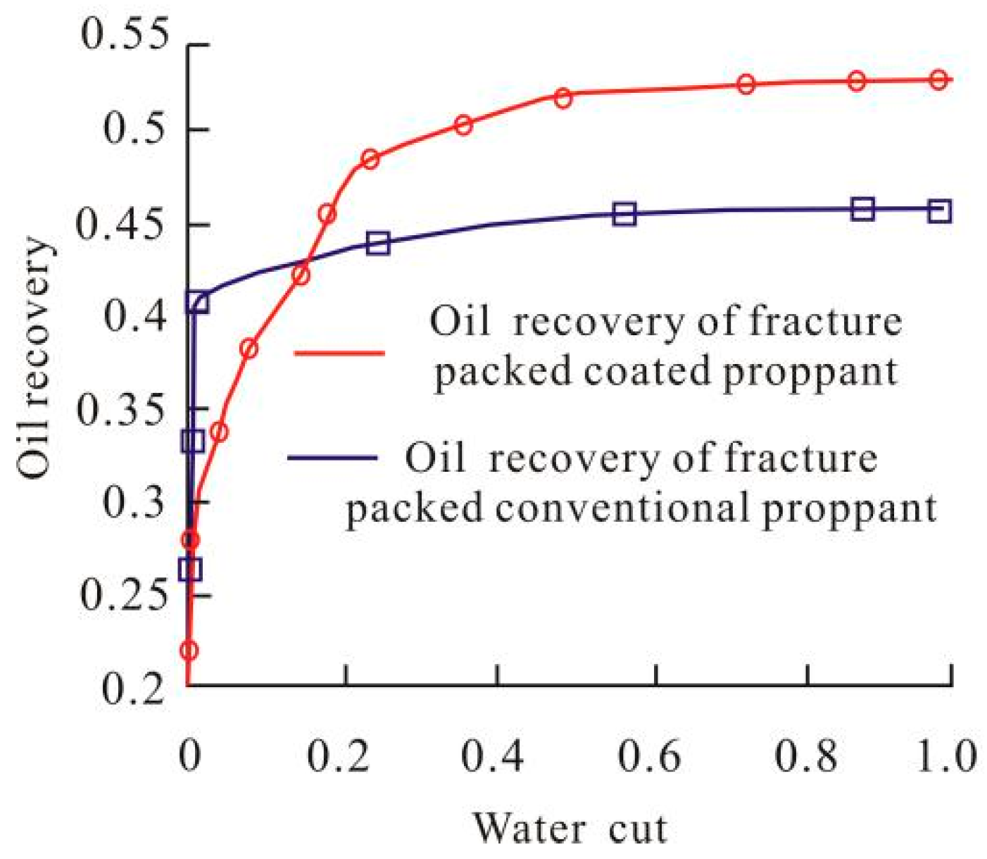
3.4. Coated Proppant Application in 3D Oil Reservoir Development

According to Figure 9, the fracture was packed with conventional proppant (scheme 1) and was developed until the water cut during production reached 98% (Figure 9). This implies that the sweeping degree of the oil reservoir was smaller (Figure 9(a1,a2)), and the water saturation around the fracture was centrally distributed (Figure 9(b1)). When the fracture was packed with the coated proppant (scheme 2) and developed until the water cut when the production reached 98% (Figure 9), the sweeping degree of the oil reservoir was bigger (Figure 9(a1,a2)), and the water saturation around the fracture was widely distributed (Figure 9(b2)). The distribution of the water saturation of the oil reservoir indicated that the fracture packed with coated proppant had WPC, which reduced the water’s ability to flow into the fracture, thus delaying the rise in the water production in the oil well, effectively extending the oil recovery period and improving oil recovery.
Figure 10 shows the results of oil recovery and water cut. Both development methods had stable oil production in the early stage. Once the water flowed in, the oil production decreased rapidly in the scheme where the fracture was packed with conventional proppant, the oil recovery no longer increased, while the water cut rose rapidly. However, the oil production decreased slowly in the scheme where the fracture was packed with coated proppant, the water cut increased slowly, and the well would not be abandoned for some time. Therefore, the recovery time would be extended. When the water cut reached 98%, the final oil recovery of the fracture packed with coated proppant was 7.7% higher than that of the fracture packed with conventional proppant.

4. Conclusions

In summary, we presented a new technique, the preparation of a hydrophobic coated proppant, for packing fractures. And then the results of the analysis of the coating via tests (FT-IR, compression resistance, temperature resistance, surface wettability, and water plugging capacity (WPC)) indicated that coated proppant, which showed compression and temperature resistance, could be prepared via the immersion method. The temperature of the coated proppant working safely reached 170 °C, and the safe compressive strength was over 27.3 MPa. The WPC of the layer packed with coated proppant exceeded that of the layer packed with conventional proppant by more than 20%. Furthermore, the fracture packed with this kind of hydrophobic coated proppant showed increased water-plugging and oil-permeability capacities and showed superior working performance to that packed with a conventional proppant, with the benefits of reducing the speed of water-cut rising and enhancing oil recovery. The final oil recovery of the fracture packed with coated proppant was 7.7% higher than that of the fracture packed with conventional proppant. The water-plugging mechanism of the layer packed with coated proppant occurs via water droplets maintaining their spherical shape when entering the intergranular pores of the coated proppant, which increases flow resistance. To the best of our knowledge, such water-plugging and oil-permeability capacities has not previously been produced via the established methods of fracture packing with conventional proppant. We expect this technique to open up an entirely new range of proppant applications and research directions.

Author Contributions

Conceptualization, H.W. and H.K.; methodology, H.W.; validation, J.L.; formal analysis, F.W.; investigation, C.W.; resources, H.W.; data curation, H.K.; writing—original draft preparation, H.K.; writing—review and editing, H.W.; supervision, F.Y.; project administration, Y.Z.; funding acquisition, H.W. All authors have read and agreed to the published version of the manuscript.

Funding

This research was funded by the 2021 Major Project of Liaoning Provincial Department of Education Grant No. LJKZ0392.

Institutional Review Board Statement

The study did not require ethical approval.

Informed Consent Statement

The study did not involve humans.

Data Availability Statement

All research data are provided in the article.

Acknowledgments

Thank you to all coauthors, editors, and reviewers.

Conflicts of Interest

The authors declare no conflict of interest.

References

  1. Ektefa, G.; Shahbazi, K. Hydraulic Fracturing Process in Tight Base Shale of Asmari Formation in Ahwaz Oilfield. J. Pet. Sci. Technol. 2020, 10, 49–55. [Google Scholar]
  2. Gao, D.; Liu, Y.; Ye, J.; Hu, Y.; Hou, S.; Li, Q.; Han, G. Performance Model for Vertical Wells with Multi-stage Horizontal Hydraulic Fractures in Water Flooded Multilayer Reservoirs. J. Pet. Sci. Technol. 2017, 7, 57–66. [Google Scholar]
  3. Hashemi, S.M.; Bashiri, G. utilizing conceptual modeling in the study of one the Iranian fractured carbonate reservoirs. J. Pet. Sci. Technol. 2013, 3, 65–76. [Google Scholar]
  4. Yildiz, T. Inflow Performance Relationship for Perforated Horizontal Wells. SPEJ 2004, 9, 265–279. [Google Scholar] [CrossRef]
  5. Wang, Z.; Wei, J.; Zhang, J.; Gong, B.; Yan, H. Optimization of perforation distribution for horizontal wells based on genetic algorithms. Pet. Sci. 2010, 7, 232–238. [Google Scholar] [CrossRef] [Green Version]
  6. Brekke, K.; Lien, S.C. New and Simple Completion Methods for Horizontal wells Improve Production Performance in High-Permeability, Thin Oil Zones. SPE Drill. Complet. 1994, 9, 205–209. [Google Scholar] [CrossRef]
  7. Li, M.; Yongxin, M.; Yi, X. A New Discovery about Inflow Control Devices in Controlling Water and Increasing Oil Recovery. J. Pet. Sci. Technol. 2017, 7, 32–40. [Google Scholar]
  8. Zernin, A.A.; Molokov, R.A.; Zharkova, K.V.; Plitkina, Y.A.; Sharipov, I.F.; Deryugin, I.I.; Nigmatullin, R.R.; Klassen, V.V. Design and prospects for the use of inflow control devices at the Tagulskoye oil-gas-condensate field (Russian). Neft. Khozyaystvo-Oil Ind. 2022, 11, 37–41. [Google Scholar]
  9. Konopczynski, M.; Moradi, M.; Krishnan, T.; Sandhu, H.; Lai, C.-L. Case Study: Oil Production Optimized With Autonomous Inflow Control Devices Offshore Malaysia. J. Pet. Technol. 2022, 74, 44–51. [Google Scholar] [CrossRef]
  10. Xie, K.; Lu, X.; Li, Q.; Jiang, W.; Yu, Q. Analysis of Reservoir Applicability of Hydrophobically Associating Polymer. SPE J. 2016, 21, 1–9. [Google Scholar] [CrossRef]
  11. Xie, K.; Lu, X.; Pan, H.; Han, D.; Hu, G.; Zhang, J.; Zhang, B.; Cao, B. Analysis of Dynamic Imbibition Effect of Surfactant in Microcracks of Reservoir at High Temperature and Low Permeability. Soc. Pet. Eng. 2018, 33, 596–606. [Google Scholar] [CrossRef]
  12. Shi, Y.; Niu, F.; Mohanty, K. Wettability Alteration with Weak Acid-Assisted Surfactant Flood. SPE J. 2023, 13, 1–15. [Google Scholar] [CrossRef]
  13. Mohammadian, E.; Junin, R.; Rahmani, O.; Idris, A.K. Effects of sonication radiation on oil recovery by ultrasonic waves stimulated water-flooding. Ultrasonics 2013, 53, 607–6014. [Google Scholar] [CrossRef] [PubMed]
  14. Chao, H.; Xue, Q.; Jing, Z.; Jian, Z.; Shun, T. Biomimetic superhydrophobic surfaces by combining mussel-inspired adhesion with lotus-inspired coating. Nanotechnology 2015, 26, 335602. [Google Scholar]
  15. Guo, Z.; Liu, W.; Su, B.-L. Superhydrophobic surfaces: From natural to biomimetic to functional. J. Colloid Interface Sci. 2011, 353, 335–355. [Google Scholar] [CrossRef]
  16. Luévano-Hipólito, R.E.; Torres-Martínez, L.M.; Cantú-Castro, L.V.F. Self-cleaning coatings based on fly ash and bismuth-photocatalysts: Bi2O3, Bi2O2CO3, BiOI, BiVO4, BiPO4. Constr. Build. Mater. 2019, 220, 206–213. [Google Scholar] [CrossRef]
  17. Shah, A.J.; Bhagchandani, G.B. Anti corrosive rubber coating. Int. J. Sci. Eng. Technol. 2013, 2, 443–447. [Google Scholar]
  18. Yang, J.; Tang, Y.; Xu, J.; Chen, B.; Tang, H.; Li, C. Durable superhydrophobic/superoleophilic epoxy/attapulgite nanocomposite coatings for oil/water separation. Surf. Coat. Technol. 2015, 272, 285–290. [Google Scholar] [CrossRef]
  19. Anokhina, T.S.; Ilyin, S.O.; Ignatenko, V.Y.; Bakhtin, D.S.; Kostyuk, A.V.; Antonov, S.V.; Volkov, A.V. Formation of Porous Films with Hydrophobic Surface from a Blend of Polymers. Polym. Sci. Ser. A 2019, 61, 619–626. [Google Scholar] [CrossRef]
  20. Paterlini, T.T.; Nogueira, L.F.B.; Tovani, C.B.; Cruz, M.A.E.; Derradi, R.; Ramos, A.P. The role played by modified bioinspired surfaces in interfacial properties of biomaterials. Biophys. Rev. 2017, 9, 683–698. [Google Scholar] [CrossRef] [Green Version]
  21. Park, I.C.; Kim, S.J. Electrochemical Characteristics in Seawater for Cold Thermal Spray-Coated Al-Mg Alloy Layer. Acta Metal. Sin. (Engl. Lett.) 2016, 29, 727–734. [Google Scholar] [CrossRef] [Green Version]
  22. Haider, A.J.; AL-Anbari, R.H.; Kadhim, G.R.; Salame, C.T. Exploring potential Environmental applications of TiO2 Nanoparticles. Energy Procedia 2017, 119, 332–345. [Google Scholar] [CrossRef]
  23. Schmitt, C.; Lebienvenu, M. Electrostatic painting of conductive composite materials. J. Mater. Process. Technol. 2003, 134, 303–309. [Google Scholar] [CrossRef]
  24. Jeong, S.; Park, S.; Cho, J. High-Performance, Layered, 3D-LiCoO2 Cathodes with a Nanoscale Co3O4 Coating via Chemical Etching. Adv. Energy Mater. 2011, 1, 368–372. [Google Scholar] [CrossRef]
  25. Liu, H. Preparation of Superhydrophobic Coatings on Zinc, Silicon, and Steel by a Solution-Immersion Technique. ACS Appl. Mater. Interfaces 2009, 1, 2086–2107. [Google Scholar] [CrossRef] [PubMed]
  26. Hu, S.; Cao, X.; Song, Y.; Li, C.; Xie, P.; Jiang, L. New responsive property of poly (e-caprolactone) as the thermal switch from superhydrophobic to superhydrophilic. Chem. Commun. 2008, 17, 2025–2027. [Google Scholar] [CrossRef]
  27. Xu, Z.; Zhao, Y.; Wang, H.; Zhou, H.; Qin, C.; Wang, X.; Lin, T. Fluorine-Free Superhydrophobic Coatings with pH-induced Wettability Transition for Controllable Oil-Water Separation. ACS Appl. Mater. Interfaces 2016, 8, 5661–5667. [Google Scholar] [CrossRef] [PubMed]
  28. Vreeburg, R.-J.; Roodhart, L.P.; Davies, D.R.; Penny, G.S. Proppant Backproduction During Hydraulic Fracturing-A New Failure Mechanism for Resin-Coated Proppants. J. Pet. Technol. 1994, 46, 884–889. [Google Scholar] [CrossRef]
  29. Shaoul, J.R.; Park, J.; Langford, M. The Effect of Resin-Coated Proppant and Proppant Production on Convergent-Flow Skin in Horizontal Wells With Transverse Fractures. SPE Prod. Oper. 2020, 35, 214–230. [Google Scholar] [CrossRef]
  30. Rassenfoss, S. Rethinking Proppant: From Liquid to Solid. J. Pet. Technol. 2015, 67, 58–59. [Google Scholar] [CrossRef]
  31. Shi, C.; Dai, J.; Li, C.; Shen, X.; Peng, L.; Zhang, P.; Wu, D.; Sun, D.; Zhao, J. A Modified Ceramic-Coating Separator with High-Temperature Stability for Lithium-Ion Battery. Polymers 2017, 9, 159–171. [Google Scholar] [CrossRef] [PubMed]
  32. Choi, J.-A.; Kimb, S.H.; Kima, D.-W. Enhancement of thermal stability and cycling performance in lithium-ion cells through the use ofceramic-coated separators. J. Power Sources 2010, 195, 6192–6196. [Google Scholar] [CrossRef]
  33. Panarin, V.Y.; Svavil’nyi, N.Y.; Khominich, A.I. An experimental study of the composite CNT/copper coating. Appl Nanosci. 2019, 9, 1111–1117. [Google Scholar] [CrossRef]
Figure 1. The molecular structures of some of the chemicals used in this work and the complete process of fabricating the sample, (a) APDMS; (b) Epoxy E44; (c) Curing agent:triethylene teramine.
Coatings 13 01238 g001
Figure 2. WPC test.
Figure 2. WPC test.
Coatings 13 01238 g002
Figure 3. Development of the simulation unit.
Coatings 13 01238 g003
Figure 4. FT−IR spectra of the coated proppant and pristine one.
Coatings 13 01238 g004
Figure 5. Surface of the coated proppant under different conditions. (a) Particle strength tester; (b) Test pressure of 5.9 MPa; (c) Test pressure of 27.3 MPa; (d) Test pressure of 91.4 MPa; (e) 90 °C, Original surface; (f) 120 °C, static temperature; (g) 170 °C, static temperature; (h) 210 °C, static temperature.
Coatings 13 01238 g005
Figure 6. Change in the contact angle.
Coatings 13 01238 g006
Figure 7. Effect of packing conditions on WPC of coated proppant.
Coatings 13 01238 g007
Figure 8. Water-plugging mechanism of the layer packed with coated proppant.
Coatings 13 01238 g008
Figure 9. Water saturation distribution of the fracture packed with different proppants. (a1) whole oil reservoir of scheme 1, (a2) whole oil reservoir of scheme 2, (b1) cross-section along the fracture of scheme 1 and (b2) cross-section along the fracture of scheme 1, scheme 1 fracture packed with conventional proppant, scheme 1 fracture packed with coated proppant.
Coatings 13 01238 g009
Figure 10. Oil recovery and water cut.
Coatings 13 01238 g010
Table 1. Relationship between the reservoir depth and the fracture closure pressure.
PetroChina Category of Reservoir Layer DepthShallow Reservoir LayerAverage Reservoir LayerMaximum Reservoir Layer
Reservoir Depth, m≈6001800 ~ 28898937.77
Average Fracture Closure Pressure, MPa5.923.791.4
Disclaimer/Publisher’s Note: The statements, opinions and data contained in all publications are solely those of the individual author(s) and contributor(s) and not of MDPI and/or the editor(s). MDPI and/or the editor(s) disclaim responsibility for any injury to people or property resulting from any ideas, methods, instructions or products referred to in the content.

