Research on the Application of Domestic High-Modulus Carbon Fiber/Epoxy Composites to Solar Panels for Solar Arrays
Abstract
:1. Introduction
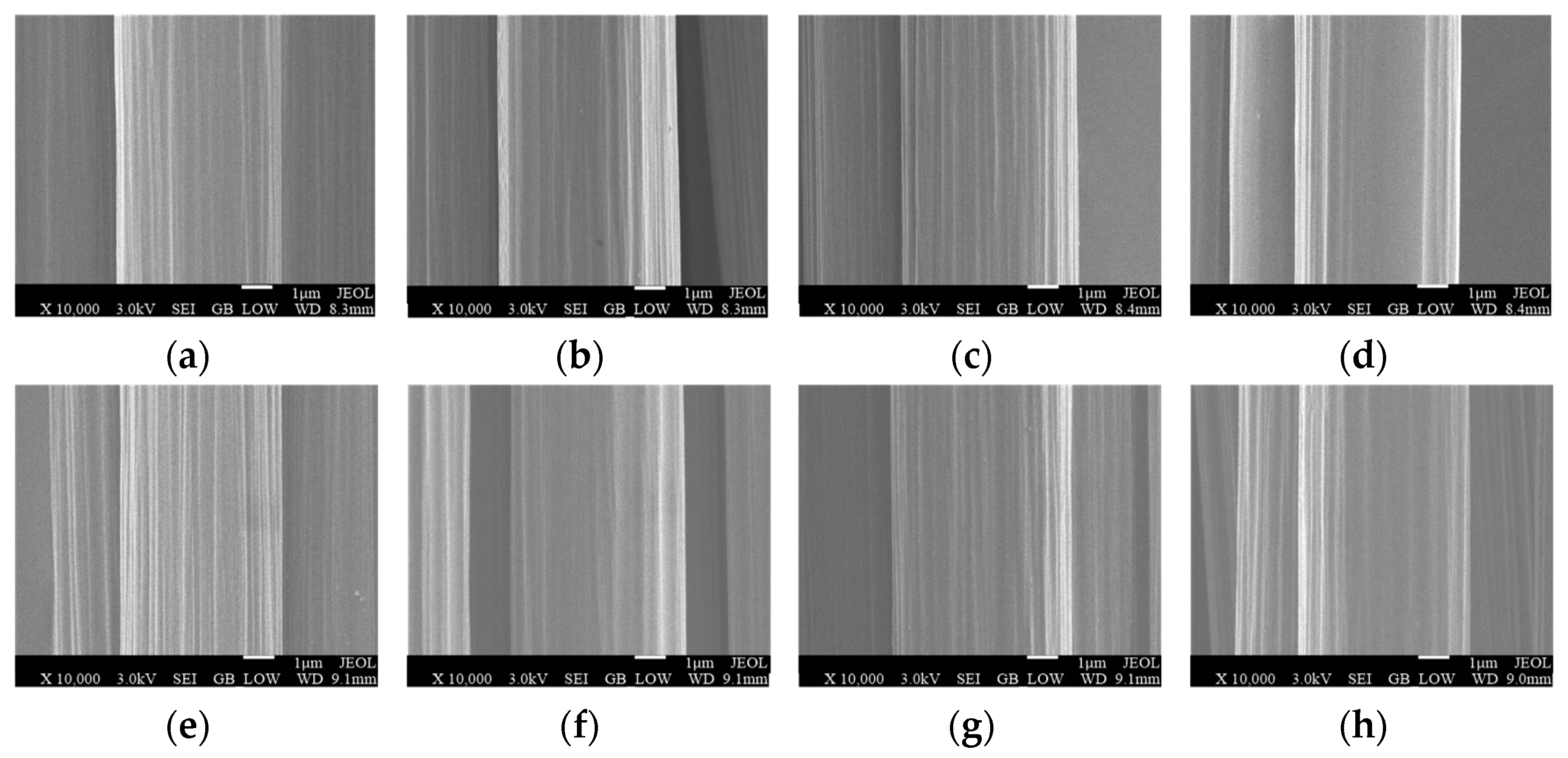
2. Comparison of Surface Physical Properties, Crystal Structure, and Performance of Two Types of Carbon Fibers
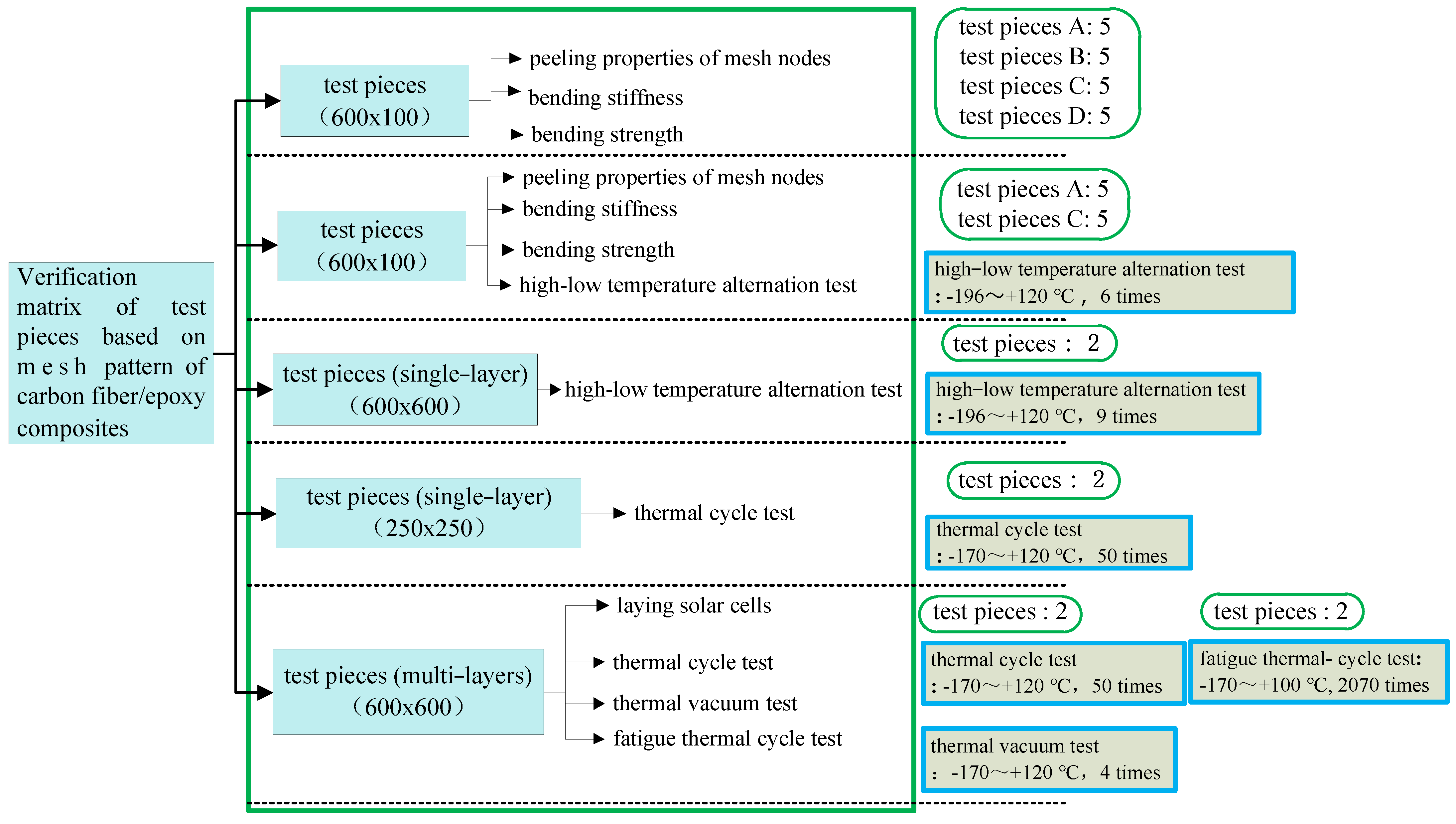
3. Key Design and Verification Matrix
4. Performance of Test Pieces Based on the CCM40J-6k Carbon Fiber/Epoxy Composite at Room Temperature
- (1)
- For test pieces with a mesh spacing of 6 mm × 4 mm, the bending stiffness of the aluminum honeycomb along the long side in the L direction is 2.4% higher, the shear stiffness is 52% higher, the failure load is 7.6% higher, and the bending strength is 7.5% higher than that of the aluminum honeycomb along the long side in the W direction.
- (2)
- For test pieces with a mesh spacing of 5.3 mm × 3.8 mm, the bending stiffness of the aluminum honeycomb along the long side in the L direction is 8.1% higher, the shear stiffness is 71% higher, the failure load is 0.4% higher, and the bending strength is 0.5% higher than that of the aluminum honeycomb along the long side in the W direction.
- (3)
- At the same mesh spacing, the shear stiffness of the test piece is significantly improved along the long side of the test piece in the L direction of the aluminum honeycomb, while the bending stiffness, failure load, and bending strength are slightly increased.
- (4)
- For the L direction of the aluminum honeycomb along the long side, and a mesh spacing of 5.3 mm × 3.8 mm compared with a mesh spacing of 6 mm × 4 mm, the bending stiffness of the test piece is 10.3% higher, the shear stiffness is 7.4% higher, the failure load is 5% higher, and the bending strength is 5% higher.
- (5)
- For the W direction of the aluminum honeycomb along the long side, and a mesh spacing of 5.3 mm × 3.8 mm compared with a mesh spacing of 6 mm × 4 mm, the bending stiffness, shear stiffness, failure load, and bending strength of the test piece are 4.5%, 4.7%, 12.5, and 12.2% higher, respectively.
- (6)
- The mechanical properties of the substrates based on the CCM40J-6k and M40JB-6k carbon fiber/epoxy composites are very similar. For a mesh spacing of 6 mm × 4 mm, the bending stiffness of the CCM40J-6k carbon-fiber substrate is 9.8 ‰ lower than that of the M40JB-6k carbon-fiber substrate, and the bending strength is 2.9% higher. Considering the average error of molding process parameters, this difference can be ignored.
- (7)
- In conclusion, when the aluminum honeycomb is in the same direction, the denser the mesh spacing is, the greater the bending stiffness, strength, shear stiffness, and failure load will be, and the corresponding weight will also be increased. This trend is consistent with the application of imported M40JB-6k carbon fiber, indicating that the performance of test pieces based on the domestic CCM40J-6k carbon fiber/epoxy composite at room temperature meets the requirements. In addition, when designing the mesh spacing of carbon fiber, it is still necessary to comprehensively consider the optimal solution between the mechanical properties and weight of the substrate.
5. Performance of Test Pieces Based on the CCM40J-6k Carbon Fiber/Epoxy Composite before and after High–Low Temperature Alternation
- (1)
- For test piece A, after high–low temperature alternation, the bending stiffness is 3.5% higher, the shear stiffness is 11% higher, the failure load is 7.1% lower, and the bending strength is 7.2% lower than that under room temperature.
- (2)
- For test piece C, after high–low temperature alternation, the bending stiffness is 9.6% higher, the shear stiffness is 1.6% lower, the failure load is 4.0% lower, and the bending strength is 4.2% lower than that under room temperature.
- (3)
- After high–low temperature alternation, the test pieces’ bending, shear, and destructive properties increase or decrease slightly. In general, the mechanical properties of the test piece based on the CCM40J-6k carbon fiber/epoxy composite are not significantly reduced compared with those before the high–low temperature alternation. After a certain number of thermal cycles, the thermal stress can be released effectively through the deformation of the resin or interface, and the mechanical properties gradually become stable. It is proven that domestic carbon fiber has high performance in combination with epoxy resin and can withstand high–low temperature alternations in space.
6. Performance of the Mesh Nodes of the Mesh Face Sheet
- (1)
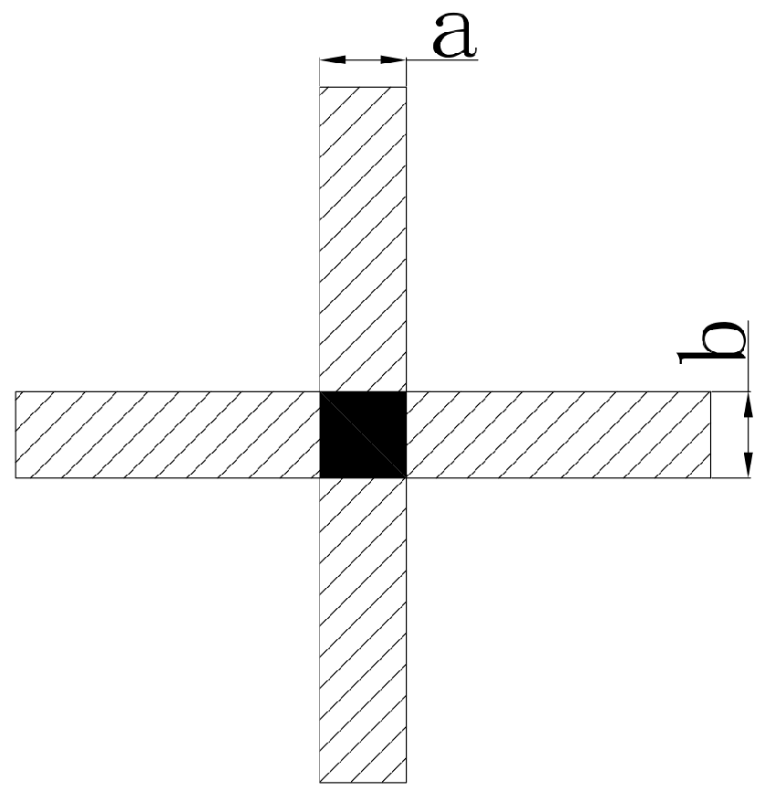
- For the domestic carbon fiber CCM40J-6k, the epoxy resin content is 31% compared with 34%, the average failure force of the mesh nodes is 44.8% higher, and the average tensile strength of the mesh nodes is 6.1% higher. Therefore, the smaller the epoxy resin content, the greater the tensile strength of the mesh nodes. However, the content of epoxy resin is also related to the surface state of the carbon fiber. The epoxy resin content should be controlled as much as possible under the condition that carbon fiber can be completely immersed.
- (2)
- Under the same epoxy resin content, the average failure force of the mesh nodes of the domestic mesh face sheet is 31.3% lower and the average tensile strength is 18.9% higher.
| Carbon Fiber | Number of Samples | Epoxy Resin Content | Average Value | |||
|---|---|---|---|---|---|---|
| a/mm | b/mm | p/N | Tensile Strength of Mesh Node/MPa | |||
| CCM40J-6k | 10 | 31% | 2.238 | 2.268 | 18.4 | 3.60 |
| 10 | 34% | 1.941 | 1.942 | 12.7 | 3.39 | |
| M40JB-6k | 10 | 34% | 2.828 | 2.298 | 18.5 | 2.85 |
7. Verification of the Thermal Cycle Tests of Substrates Based on Domestic and Imported Carbon Fiber/Epoxy Composites
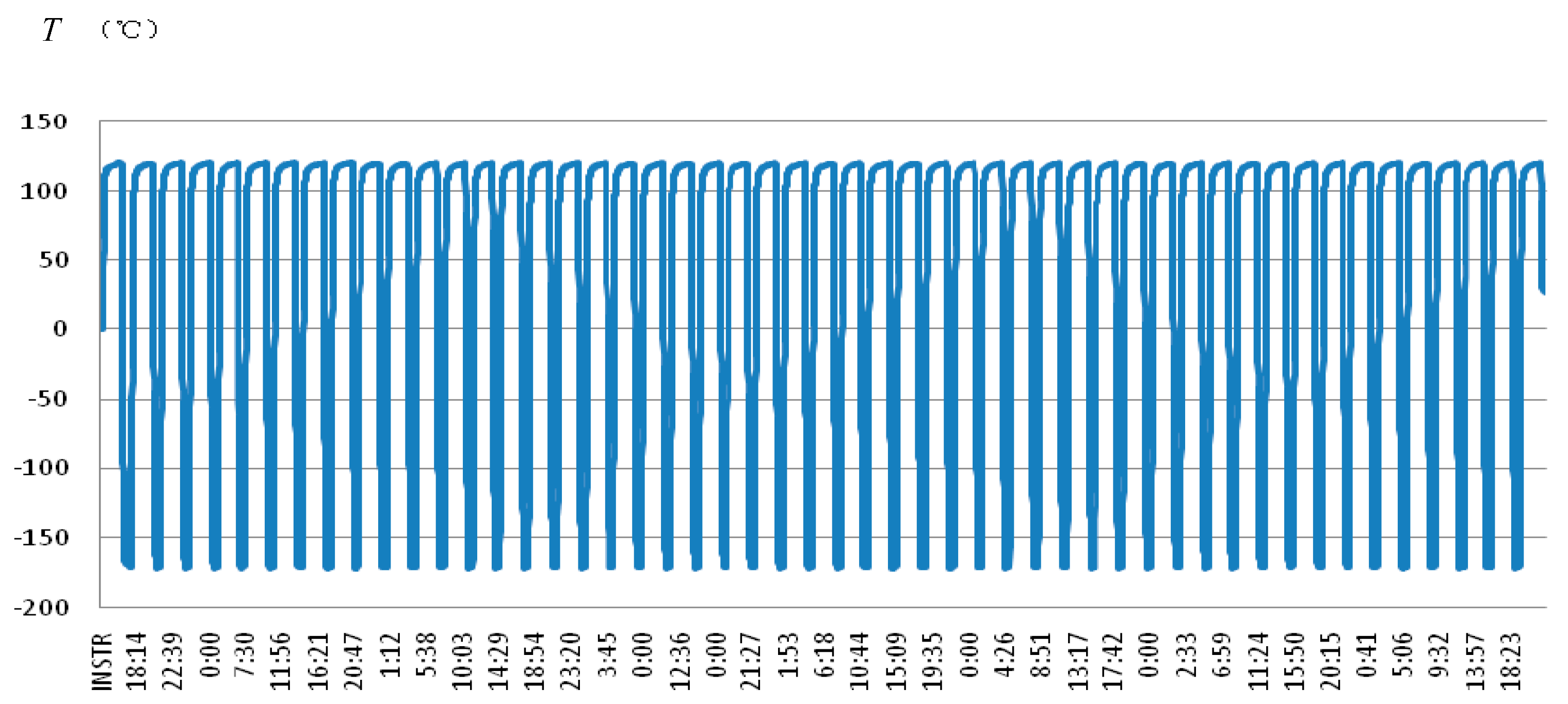
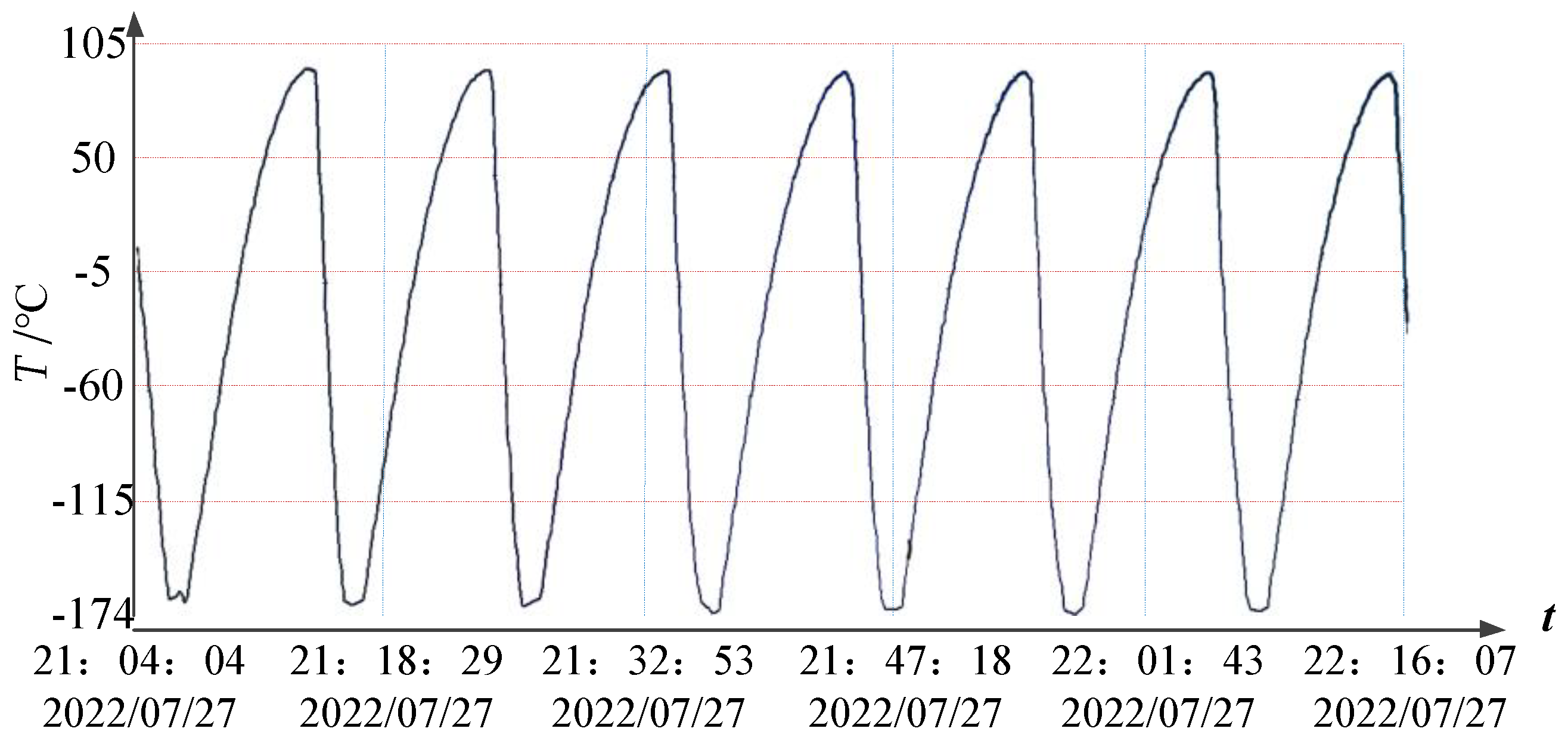
- Temperature: For high temperature, the temperature was kept at +120 (±5) °C; for low temperature, the average temperature was lower than −170 °C;
- Cooling rate: The maximum capacity of the equipment was used for cooling from high-temperature working conditions to low-temperature working conditions;
- Heating rate: The heating time was about 45 min, from −165 °C to 80 °C, and the maximum heating rate was not less than 40 °C/min;
- Number of cycles: 50 cycles in total, starting from the high-temperature working conditions.
- (1)
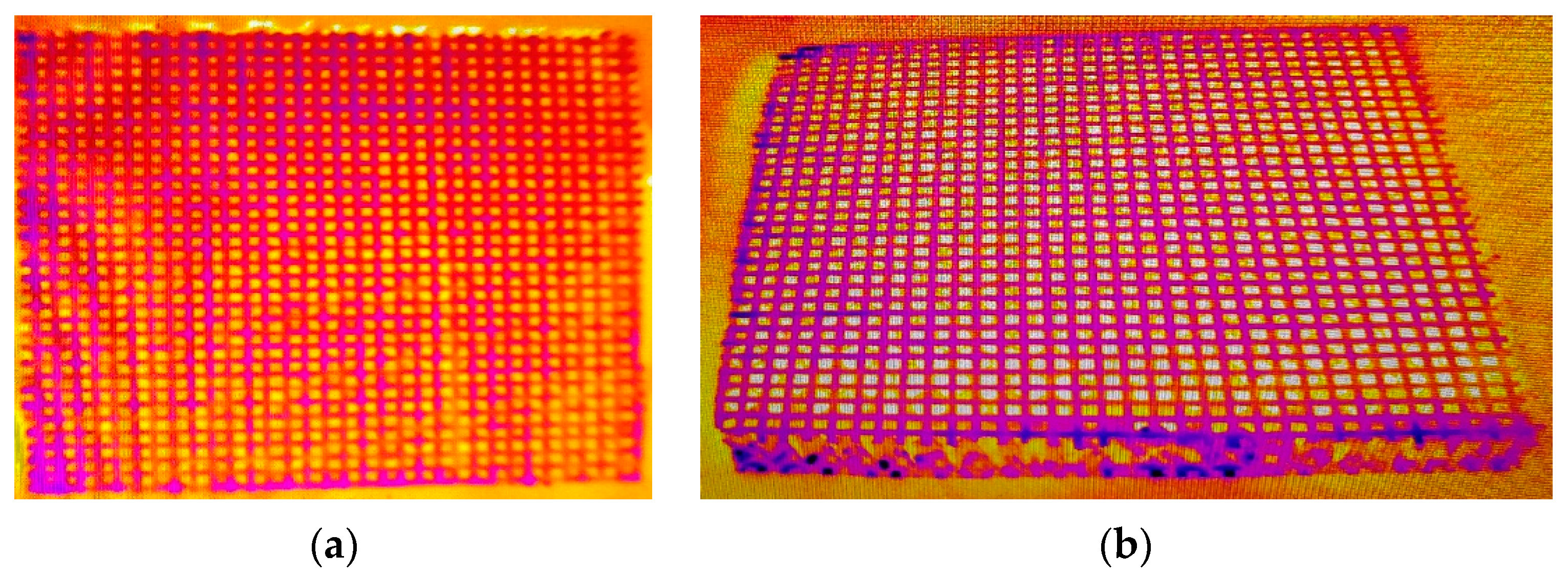
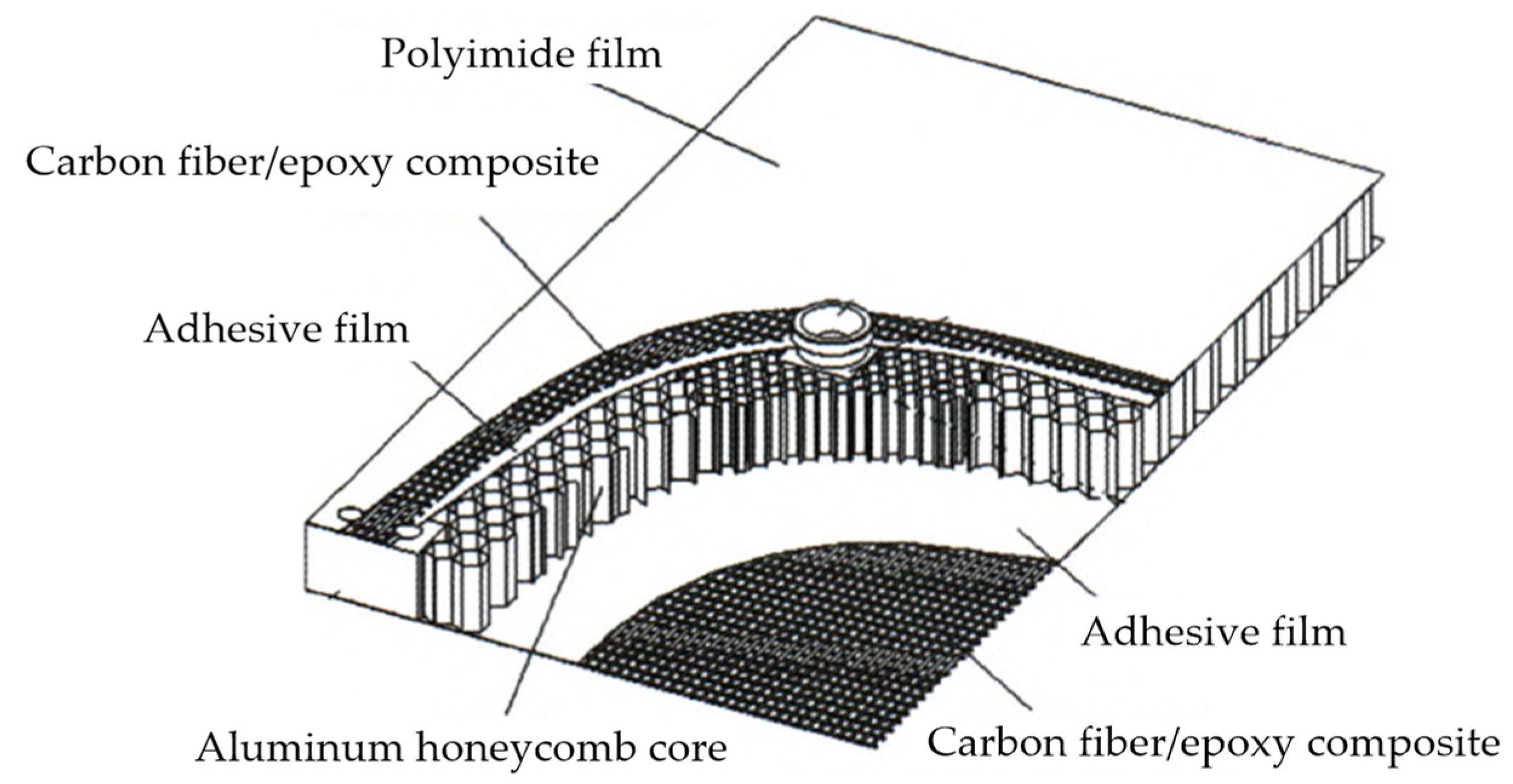
- The two test pieces were in good bonding condition at the carbon-fiber orthogonal joints on both sides, without debonding joints. The bonding condition between carbon fiber and the aluminum honeycomb core, and the bonding condition between polyimide film and carbon fiber were both stable, without debonding problems.
- (2)
- The nondestructive detection of the two test pieces using an infrared thermal imager showed that the bonding at the mesh nodes and between the carbon fiber and aluminum honeycomb core was in good condition, which indicated that the domestic carbon-fiber substrate (CCM40J-6k) could adapt to temperature alternation, and further proved the feasibility of the application of domestic carbon fiber in large-size structural part.
8. Verification of the Thermal Environment Test of a Solar Panel Based on the CCM40J-6k Carbon Fiber/Epoxy Composite
8.1. Test Piece of Substrate
- (1)
- Area 1 is the single layer with a mesh spacing of 4 mm × 6 mm (top layer);
- (2)
- Area 2 has two layers (top layer + second layer with a mesh spacing of 6 mm × 4 mm);
- (3)
- Area 3 has three layers (top layer + second layer with a mesh spacing of 6 mm × 4 mm + third layer with a mesh spacing of 4 mm × 6 mm);
- (4)
- Area 4 has four layers (top layer + second layer with a mesh spacing of 6 mm × 4 mm + third layer with a mesh spacing of 4 mm × 6 mm + fourth layer with a mesh spacing of 6 mm × 4 mm);
- (5)
- Area 5 has three layers (top layer + second layer with a mesh spacing of 6 mm × 4 mm + third layer with a mesh spacing of 4 mm × 6 mm);
- (6)
- Area 6 has three layers (top layer + second layer with a mesh spacing of 6 mm × 4 mm + third layer with a mesh spacing of 4 mm × 6 mm).

8.2. Test Piece of Solar Panel
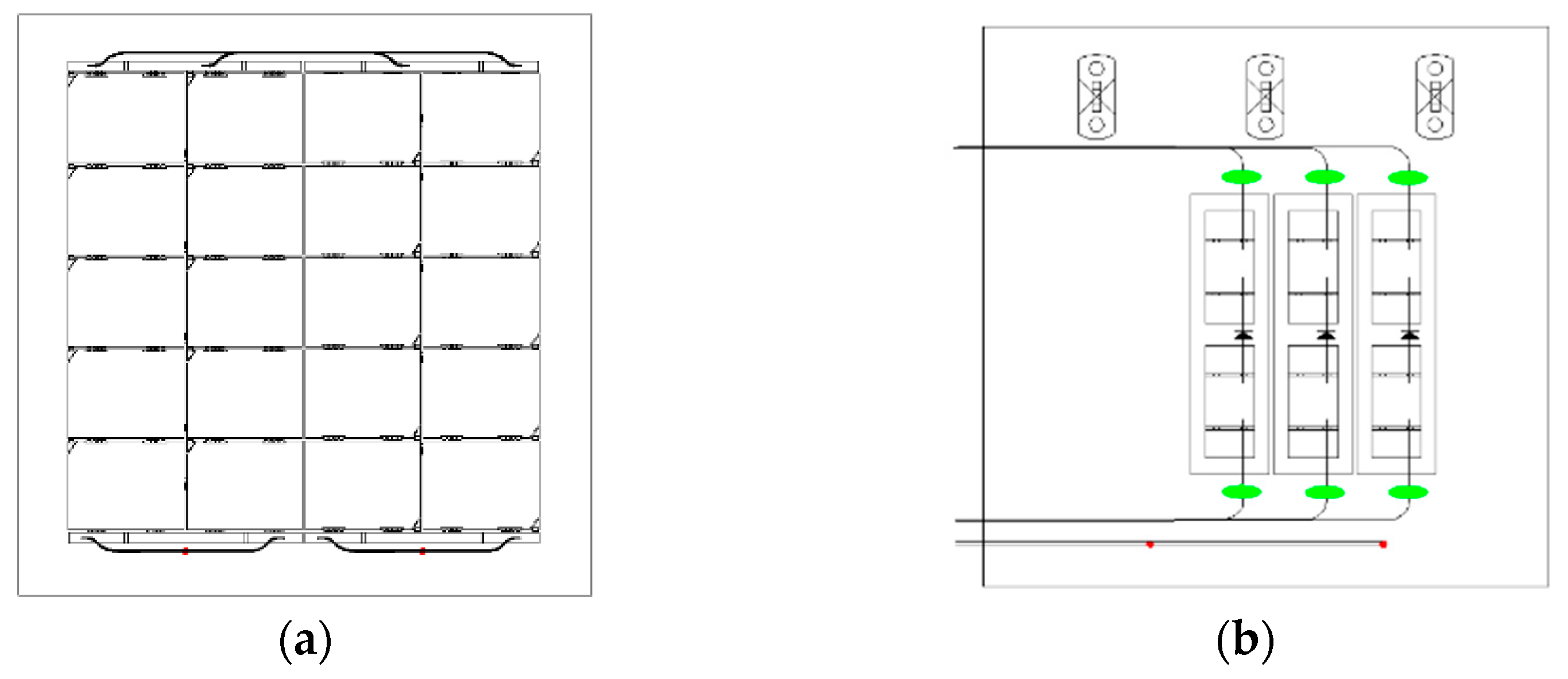
8.3. Atmospheric Thermal Cycle Test
8.4. Thermal Vacuum Test
- (1)
- Pressure, ≤1.3 × 10⁻³ Pa;
- (2)
- Temperature range, −170~+120 °C;
- (3)
- Changing rate of temperature, according to the predictive value of changing rate when entering and exiting the shadow, which should not be lower than 10 °C/min;
- (4)
- Number of cycles, 4 cycles.
8.5. Test Results
- (1)
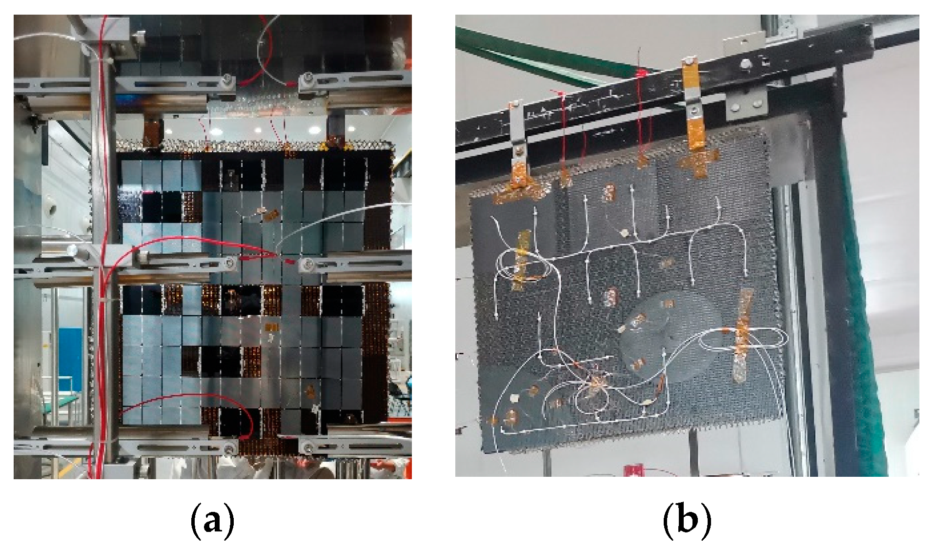
- Before and after the test, the circuit interconnection and bus ribbon of the test piece were inspected. The appearance of the circuit interconnection and bus ribbon was unchanged. After the test, the cracks in the solar cell and the glass cover were inspected, and no new cracks were found. The solder joints were free of desoldering, the wires were free of damage, and the adhesive layer was intact without desoldering.
- (2)
- Before and after the test, the conduction and insulation of the solar cell circuit of the test piece were checked, and the results were normal.
- (3)
- Before and after the test, the surface of carbon fiber was inspected, and no debonding was found on the cross node of the mesh face sheet on the back of the test piece and the front of the substrate with polyimide film.
- (4)
- The solar panel based on the domestic carbon fiber/epoxy composite successfully passed the thermal environment assessment, indicating that it has the ability to withstand temperature alternation in space.
9. Verification of Fatigue Thermal-Cycle Test of Solar Panel Based on the CCM40J-6k Carbon Fiber/Epoxy Composite
9.1. Test Piece of Solar Panel
9.2. Test Conditions
- (1)
- Ambient air pressure, normal pressure;
- (2)
- Temperature range, −170~+ 100 °C;
- (3)
- Changing rate of temperature, according to the predictive value of changing rate when entering and exiting the shadow, which should not be lower than 10 °C/min;
- (4)
- Number of cycles, 2070 cycles.
9.3. Test Process
9.4. Test Results
- (1)
- Before and after the test, the appearances of the solar cell, diode, interconnection, bus ribbon, conductor, solder joint, current distribution module, and fixing pile of cable were intact without debonding.
- (2)
- Before and after the test, the appearance of the solar cell and its glass cover was intact, and the insulation resistance value between the solar cell circuit and the substrate was above 100 MΩ.
- (3)
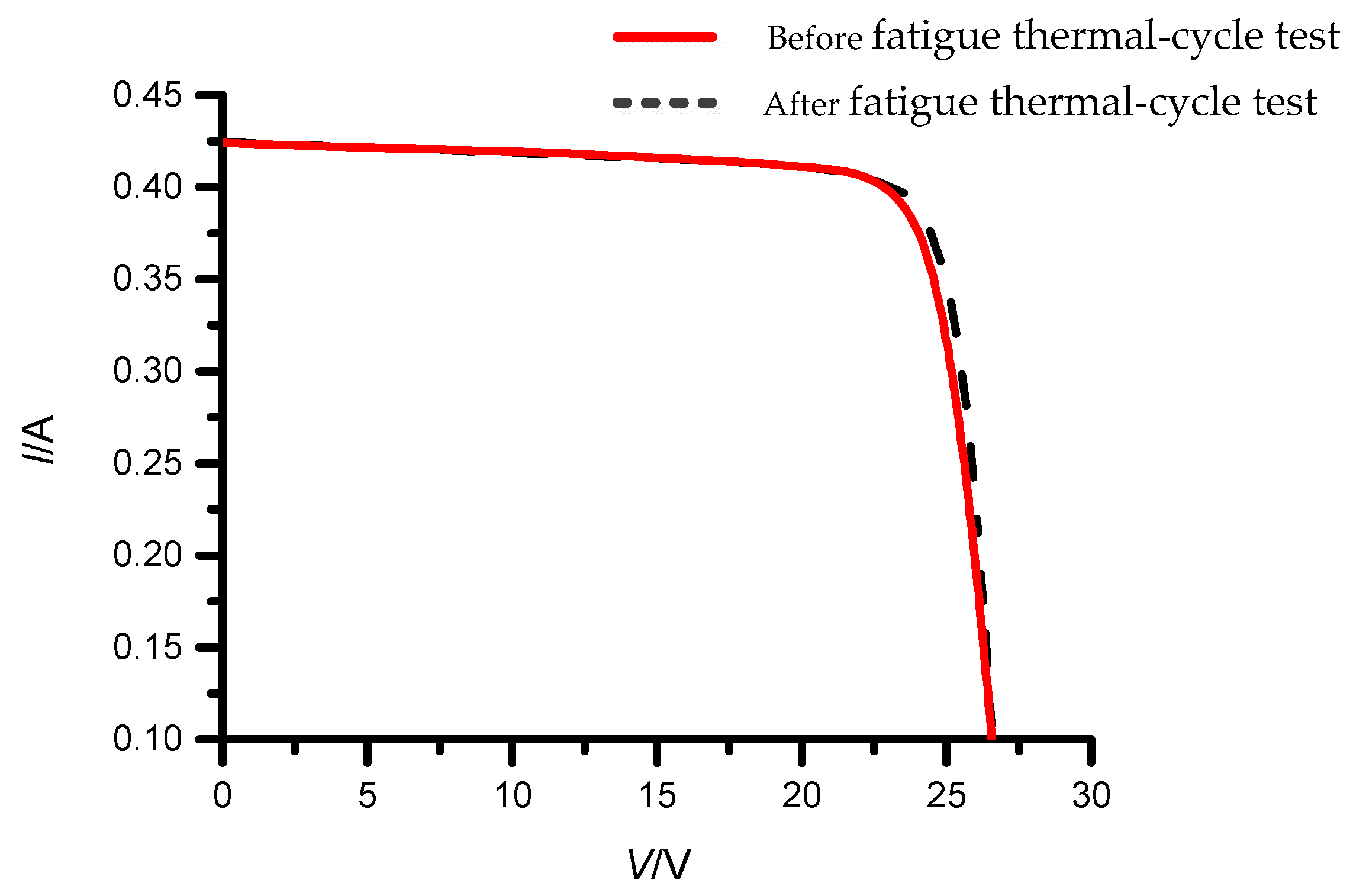
- The changing rates of the open-circuit voltage Voc and the short-circuit current Isc before and after the test were 0.55% and 0.24%, respectively, with very little change.
- (4)
- Before and after the test, the surface of the substrate was inspected, and no debonding was found on the cross node of the mesh face sheet on the back of the test piece and the front of the substrate with polyimide film.
- (5)
- The solar panel made from a domestic carbon fiber/epoxy composite successfully passed the fatigue thermal-cycle test, indicating that it could withstand temperature changes over the satellite’s lifetime, and the substrate and the solar cell were well matched.
| Item | Test Result | ||
|---|---|---|---|
| Before Test | After Test | Changing Rate | |
| Open-circuit voltage (Voc)/V | 26.873 | 26.888 | 0.55% |
| Short-circuit current (Isc)/A | 0.423 | 0.424 | 0.24% |
| Optimum operating voltage (Vmp)/V | 23.670 | 23.702 | 0.14% |
| Optimum operating current (Imp)/A | 0.397 | 0.398 | 0.25% |
| Maximum power (Pmax)/W | 9.409 | 9.437 | 0.30% |
| Fill factor (FF) | 0.826 | 0.827 | 0.01% |
| Open-circuit voltage (Voc)/V | 26.873 | 26.888 | 0.55% |
| Short-circuit current (Isc)/A | 0.423 | 0.424 | 0.24% |
| Optimum operating voltage (Vmp)/V | 23.670 | 23.702 | 0.14% |
10. Conclusions
- (1)
- As compared with M40JB-6k, the surface physical properties, crystal structure, and mechanical properties of CCM40J-6k are basically the same. The production process of the substrate for a solar panel based on CCM40J-6k can adopt that of M40JB-6k carbon fiber.
- (2)
- At the same mesh spacing, the shear stiffness of the CCM40J-6k test piece can be significantly improved along the long side of the test piece in the L direction of the aluminum honeycomb, while the bending stiffness, failure load, and bending strength increase slightly. Therefore, when designing the direction of the aluminum honeycomb and the mesh face sheet, the optimal solution of the mechanical properties of the substrate should be comprehensively considered.
- (3)
- Under the same epoxy resin content, the tensile strength of the CCM40J-6k mesh nodes is 18.9% higher than that of the imported carbon-fiber mesh nodes. A smaller amount of epoxy resin can significantly reduce product weight while ensuring carbon fibers can be completely immersed.
- (4)
- After the CCM40J-6k test piece undergoes thermal shock, the deformation of the resin or interface can effectively relieve thermal stress, resulting in stabilizing mechanical properties. Compared to the results before the experiment, the mechanical properties are slightly decreased, and the impact is acceptable. Through comparative thermal cycling tests of substrates based on two types of carbon fibers, it has been proven that the comprehensive performance of CCM40J-6k is equivalent to that of the imported M40JB-6k.
- (5)
- The CCM40J-6k solar panel passed the thermal vacuum and fatigue thermal cycling tests with 2070 cycles. The change rates of the open-circuit voltage and the short-circuit current of triple-junction gallium arsenide solar cells after the fatigue thermal cycling test are 0.55% and 0.24%, respectively. The appearance of the solar cell and glass cover is intact, and the insulation performance of the solar cell circuit is stable. This proves that the CCM40J-6k substrate and triple-junction gallium arsenide solar cells have high compatibility. A solar panel based on the domestic carbon fiber CCM40J-6k can withstand temperature shocks during the total on-orbit life of the satellite.
- (6)
- Based on the research results of this study, future space application verification of the domestic carbon fiber CCM40J-6k on full-size solar panels and solar arrays will be carried out.
Author Contributions
Funding
Institutional Review Board Statement
Informed Consent Statement
Data Availability Statement
Acknowledgments
Conflicts of Interest
References
- Tang, E.L.; Li, Z.; Zhang, Q.M.; Wang, M.; Xiang, S.H.; Liu, S.H.; He, L.P.; Han, Y.F.; Xia, J.; Wang, H.L.; et al. Discharges of plasma induced by hypervelocity impact on the solar array with different substrate structures. Int. J. Appl. Electrom. 2016, 51, 337–347. [Google Scholar]
- Yoon, M.S.; Shim, Y.B.; Han, Y.G. Influence of the thickness and doping concentration in p- and n-type poly-Si layers on the efficiency of a solar cell based on a carbon fiber. J. Opt. Soc. Korea 2015, 19, 199–205. [Google Scholar] [CrossRef]
- Yu, G.; Yang, D.Z.; He, S.Y.; Liu, Y.; Jiang, S.L.; Li, Z.J. A study on damage effect of vacuum thermocycling on M40J-epoxy composites. J. Reinf. Plast. Comp. 2005, 24, 1705–1711. [Google Scholar] [CrossRef]
- Wang, Q.Q.; Wang, P.P.; Qian, X.; Zhang, Y.G.; Yang, W. Effect of water-soluble thermoplastic polyimide sizing agent on interfacial properties of domestic high strength and high modulus carbon fiber reinforced composites br. J. Mater. Sci. 2023, 51, 174–182. [Google Scholar]
- Bowman, S.; Hu, X.Y.; Jiang, Q.R.; Qiu, Y.P.; Liu, W.S.; Wei, Y. Effects of Graphene-Oxide-Modified coating on the properties of Carbon-Fiber-Reinforced polypropylene composites. Coatings 2018, 8, 149. [Google Scholar] [CrossRef] [Green Version]
- Dong, X.W.; Li, A.; Yan, Y.Y.; Wang, P. Enhanced mechanical and damping properties of carbon fiber/epoxy composites by introducing the microcapsule particles. Polym. Compos. 2023, 43, 4609–4625. [Google Scholar] [CrossRef]
- Tonga, D.A.; Akbar, M.F.; Shrifan, N.; Jawad, G.N.; Ghazali, N.A.; Mohamed, M.; Al-Gburi, A.; Ab Wahab, M.N. Nondestructive evaluation of Fiber-Reinforced polymer using microwave techniques: A review. Coatings 2023, 13, 590. [Google Scholar] [CrossRef]
- Samson, P.E.; Kumaran, S.S.; Shanmugam, V.; Das, O. The effect of fiber orientation and stacking sequence on carbon/Kevlar/epoxy intraply hybrid composites under dynamic loading conditions. Polym. Advan. Technol. 2023, 34, 1585–1598. [Google Scholar] [CrossRef]
- Ma, Y.Y.; Wang, J.T.; Lu, K.; Xiang, Y.; Liu, Y.Q. The evolution of carbon fiber elements and their effects on fiber mechanical properties from molecular dynamics. Comp. Mater. Sci. 2023, 220, 112029. [Google Scholar] [CrossRef]
- Cariou, R.; Boulanger, B.; Voarino, P.; Roujol, Y.; Couderc, R.; Boirard, H.; Rapp, E.; Bourcier, F. Characterization of solar array’s cells to substrate bonding interface. In Proceedings of the European Space Power Conference (ESPC), Juan-les-Pins, France, 30 September–4 October 2019. [Google Scholar]
- Li, W.W.; Kang, H.L.; Xu, J.; Liu, R.G. Microstructures of high-strength high-modulus carbon fibers and high-modulus carbon fibers. Acta Polym. Sin. 2018, 49, 380–388. [Google Scholar]
- Wang, Y.F.; Liu, G.; Peng, G.Q.; Li, S.L.; Xie, F.Y. Interfacial properties of domestic T700 carbon fiber/bismaleimide composites. J. Mater. Sci. 2018, 46, 140–145. [Google Scholar]
- Qi, G.C.; Liu, J.X.; Yu, Y.L.; Zhang, B.M.; Du, S.Y. Assessment of interfacial adhesion between carbon fiber and epoxy by transverse fiber bundle and single fiber fragmentation tests. In Proceedings of the 20th International Conference on Composite Materials (ICCM), Copenhagen, Denmark, 19–24 July 2015. [Google Scholar]
- Stepashkin, A.A.; Mohammad, H.; Makarova, E.D.; Odintsova, Y.V.; Laptev, A.I.; Tcherdyntsev, V.V. Deformation behavior of single carbon fibers impregnated with polysulfone by polymer solution method. Polymers 2023, 15, 570. [Google Scholar] [CrossRef] [PubMed]
- Zhang, F.B.; Zhang, J.Q.; Zhu, Y.; Wang, X.X.; Jin, Y.Y. Microstructure and properties of polytetrafluoroethylene composites modified by carbon materials and aramid fibers. Coatings 2020, 10, 1103. [Google Scholar] [CrossRef]
- Pang, L.; Sun, J.W.; Zhao, K.X.; Dai, S.L.; Liu, G.; Peng, C. Exprimental study on thermal conductivity enhancement technique for space carbon fiber shell structure. Chin. Space Sci. Technol. 2019, 39, 13–18. [Google Scholar]
- Xu, Y.X.; Gu, Y.Z.; Ma, Q.S. Experimental analysis of properties of several domestic high-modulus carbon fibers. Acta Mater. Compos. Sin. 2016, 33, 1905–1914. [Google Scholar]
- Su, Q.Y.; Liu, H.X.; Wei, S.H. The control of the epoxy resin content on satellite solar battery’s grid hard substrates. Fiber Reinf. Plast/Compos. 2019, 12, 101–105. [Google Scholar]
- Peng, G.Q.; Li, K.; Zhong, X.Y.; Li, G.L.; Li, W.D.; Bao, J.W.; Wang, J. Mechanical properties of unidirectional carbon fiber composites based on domestic T800H carbon fiber, M40J graphite fiber and their mixtures. New Carbon Mater. 2020, 35, 776–784. [Google Scholar] [CrossRef]
- Wang, S.; Chen, Z.H.; Li, W. The comparison of surface state and interface between composites of different carbon fibers. Rare Metal Mat. Eng. 2007, 36, 608–610. [Google Scholar]
- Li, G.L.; Peng, G.Q.; Zhong, X.Y. Characterization of domestic high performance carbon fibers and mechanical properties of carbon fibers reinforced matrix composites. J. Mater. Sci. 2020, 48, 74–81. [Google Scholar]
- Ou, Q.R.; Ji, P.J.; Xiao, J.; Wu, L.; Wang, L. Cyanate ester for domestic T800 carbon fiber and its composites properties. J. Mater. Sci. 2019, 47, 125–131. [Google Scholar]
- Gao, Y.; Yang, D.Z.; He, S.Y.; Li, Z.J. Effect of vacuum thermocycling on properties of unidirectional M40J/AG-80 composites. In Proceedings of the 17th International Conference on Protection of Materials and Structures from Space Environment, Toronto, ON, Canada, 10–13 May 2006; pp. 209–215. [Google Scholar]
- Khosravani, M.R. Composite materials manufacturing processes. In Proceedings of the 2nd International Conference on Mechanical and Aerospace Engineering (ICMAE 2011), Bangkok, Thailand, 29–31 July 2011; pp. 1361–1367. [Google Scholar]
- Ma, Y.; Yokozeki, T.; Ueda, M.; Yang, Y.Q.; Hamada, H.; Sugahara, T. Simulation on the mechanical performance and fracture behavior of unidirectional carbon fiber-reinforced composites. J. Compos. Mater. 2021, 55, 3639–3649. [Google Scholar] [CrossRef]
- Yan, B.; Zhu, S.H.; Tong, M.B.; Pan, S. Experimental study on the mechanical properties of laminates made of thin carbon fiber plies. Compos. Struct. 2020, 245, 112336. [Google Scholar] [CrossRef]
- Zhang, X.J.; Shi, Y.C.; Li, Z.X. Experimental study on the tensile behavior of unidirectional and plain weave CFRP laminates under different strain rates. Compos. Part B-Eng. 2019, 164, 524–536. [Google Scholar] [CrossRef]
- Ma, Y.; Yang, Y.Q.; Sugahara, T.; Hamada, H. A study on the failure behavior and mechanical properties of unidirectional fiber reinforced thermosetting and thermoplastic composites. Compos. Part B-Eng. 2016, 99, 162–172. [Google Scholar] [CrossRef]
- Gan, K.W.; Wisnom, M.R.; Hallett, S.R. Effect of high through-thickness compressive stress on fibre direction tensile strength of carbon/epoxy composite laminates. Compos. Sci. Technol. 2014, 90, 1–8. [Google Scholar] [CrossRef] [Green Version]
- Hashimoto, M.; Okabe, T.; Sasayama, T.; Matsutani, H.; Nishikawa, M. Prediction of tensile strength of discontinuous carbon fiber/polypropylene composite with fiber orientation distribution. Compos. Part A-Appl. S. 2012, 43, 1791–1799. [Google Scholar] [CrossRef]
- Feng, Z.Y.; Mou, H.L.; Xie, J.; Gong, T.C. Hygrothermal environment effects on mechanical properties of T700/3228 CFRP laminates. Mater. Test. 2019, 61, 857–863. [Google Scholar] [CrossRef]
- Zhang, Y.Q.; Li, Y.; Zhang, J.L.; Pan, J.W.; Zhang, L.; Tan, F.L.; Wei, H.J.; Zhang, W. High-Temperature effect on the tensile mechanical properties of unidirectional carbon Fiber-Reinforced polymer plates. Materials 2021, 14, 7214. [Google Scholar] [CrossRef]




| Fiber Name | 2θ (°) | d (nm) | Lc (nm) |
|---|---|---|---|
| Imported M40JB-6k | 25.800 | 0.3450 | 2.7 |
| Domestic CCM40J-6k | 25.919 | 0.3435 | 2.4 |
| Item | Domestic CCM40J-6k | Imported M40JB-6k |
|---|---|---|
| Tensile modulus/GPa | 388 | 377 |
| Tensile strength MPa | 5035 | 4410 |
| Elongation/% | 1.30 | 1.2 |
| Number of fibers per bundle | 6000 | 6000 |
| Weight per km/(g/1000 m) | 227 | 225 |
| Density/(g/cm3) | 1.77 | 1.77 |
| Test Piece | Mesh Spacing | Direction of Aluminum Honeycomb Core | Number of Samples | Average Value | |||
|---|---|---|---|---|---|---|---|
| Bending Stifness/(N.mm2) | Shear Stiffness /(KN) | Failure Load/N | Bending Strength /MPa | ||||
| Test piece A | 6 mm × 4 mm | L direction along the long side | 5 | 3.40 × 10⁸ | 78.0 | 241 | 36.0 |
| Test piece B | 6 mm × 4 mm | W direction along the long side | 5 | 3.32 × 10⁸ | 49.0 | 224 | 33.5 |
| Test piece C | 5.3 mm × 3.8 mm | L direction along the long side | 5 | 3.75 × 10⁸ | 83.8 | 253 | 37.8 |
| Test piece D | 5.3 mm × 3.8 mm | W direction along the long side | 5 | 3.47 × 10⁸ | 51.3 | 252 | 37.6 |
| Test Piece | Mesh Spacing | Direction of Aluminum Honeycomb Core | Number of Samples | Average Value | |
|---|---|---|---|---|---|
| Bending Stiffness/(N.mm2) | Bending Strength /MPa | ||||
| CCM40J-6k | 6 mm × 4 mm | L direction along the long side | 3 | 2.01 × 10⁸ | 48.3 |
| M40JB-6k | 6 mm × 4 mm | L direction along the long side | 3 | 2.03 × 10⁸ | 46.9 |
| Test Piece | Mesh Spacing | Direction of Aluminum Honeycomb Core | Number of Samples | Test Timing | Average Value | |||
|---|---|---|---|---|---|---|---|---|
| Bending Stiffness /(N.mm2) | Shear Stiffness /(KN) | Failure Load/N | Bending Strength /MPa | |||||
| Test piece A | 6 mm × 4 mm | L direction along the long side | 5 | At room temperature | 3.40 × 10⁸ | 78.0 | 241 | 36.0 |
| 5 | After high–low temperature alternation | 3.52 × 10⁸ | 86.6 | 224 | 33.4 | |||
| Test piece C | 5.3 mm × 3.8 mm | L direction along the long side | 5 | At room temperature | 3.75 × 10⁸ | 83.8 | 253 | 37.8 |
| 5 | After high–low temperature alternation | 4.11 × 10⁸ | 82.5 | 243 | 36.2 | |||
Disclaimer/Publisher’s Note: The statements, opinions and data contained in all publications are solely those of the individual author(s) and contributor(s) and not of MDPI and/or the editor(s). MDPI and/or the editor(s) disclaim responsibility for any injury to people or property resulting from any ideas, methods, instructions or products referred to in the content. |
© 2023 by the authors. Licensee MDPI, Basel, Switzerland. This article is an open access article distributed under the terms and conditions of the Creative Commons Attribution (CC BY) license (https://creativecommons.org/licenses/by/4.0/).
Share and Cite
Yang, S.; Shao, L.; Ma, J.; Ren, S.; Chen, Y. Research on the Application of Domestic High-Modulus Carbon Fiber/Epoxy Composites to Solar Panels for Solar Arrays. Coatings 2023, 13, 1259. https://doi.org/10.3390/coatings13071259
Yang S, Shao L, Ma J, Ren S, Chen Y. Research on the Application of Domestic High-Modulus Carbon Fiber/Epoxy Composites to Solar Panels for Solar Arrays. Coatings. 2023; 13(7):1259. https://doi.org/10.3390/coatings13071259
Chicago/Turabian StyleYang, Shuli, Limin Shao, Jingya Ma, Shouzhi Ren, and Yunshuai Chen. 2023. "Research on the Application of Domestic High-Modulus Carbon Fiber/Epoxy Composites to Solar Panels for Solar Arrays" Coatings 13, no. 7: 1259. https://doi.org/10.3390/coatings13071259
APA StyleYang, S., Shao, L., Ma, J., Ren, S., & Chen, Y. (2023). Research on the Application of Domestic High-Modulus Carbon Fiber/Epoxy Composites to Solar Panels for Solar Arrays. Coatings, 13(7), 1259. https://doi.org/10.3390/coatings13071259


