Article

Preparation of Molybdenum Coatings by Molten Salt Electrodeposition in Na3AlF6-NaF-Al2O3-MoO3 System

1
School of Metallurgy Engineering, Anhui University of Technology, Maanshan 243032, China
2
Department of Metallurgy, Graduate School of Engineering, Tohoku University, Sendai 980-8579, Japan
3
Department of Materials Science and Engineering, Norwegian University of Science and Technology, 7491 Trondheim, Norway
*
Authors to whom correspondence should be addressed.
Coatings 2023, 13(7), 1266; https://doi.org/10.3390/coatings13071266
Submission received: 17 June 2023 / Revised: 13 July 2023 / Accepted: 14 July 2023 / Published: 19 July 2023
(This article belongs to the Special Issue Advanced Surface Technology and Application)

Abstract

:
In this paper, electrodeposition of a molybdenum coating was conducted in Na3AlF6-NaF-Al2O3-MoO3 molten salts at 930 °C to investigate the availability of preparation of thick molybdenum coatings. The effects of current density and electrodeposition time on the morphology of the produced molybdenum coating were studied. With the increase of current density (10~70 mA·cm−2), the coating thickness was increased from 10 μm to 30 μm, with all the current efficiency above 97%. Under a current density of 30 mA/cm2, with the rise of electrodeposition time (10~60 min), three stages of the deposit growth were observed, including the formation of a large number of fine crystals, transformation into fibrous morphology and well-developed faceted grains. The formation of a large number of fine crystals at the initial stage of the electrodeposition could facilitate electroplating molybdenum coatings with good quality at higher current density and longer duration. Thus electrodeposition at a current density of 100 mA·cm−2 for 3 h has been performed, resulting in the preparation of relatively flat, dense, and coherent molybdenum coatings with a thickness of 140 μm on a nickel substrate, with a current efficiency above 85%. It is anticipated that the electrodeposition of molybdenum coatings in the present molten system is suitable for electroplating thick molybdenum coatings.

1. Introduction

Molybdenum (Mo) possesses excellent properties, such as high thermal and electrical conductivity, high modulus of elasticity, high strength at elevated temperatures, and good resistance to corrosion [1,2], which make it a suitable candidate for high-temperature applications, the automotive industry, and space application [2,3]. However, it is very expensive and difficult to fabricate, so it is worthwhile to establish a technique to coat inexpensive metal substrates with molybdenum [4,5].
Molybdenum coatings are often produced by means of thermal spraying [6,7,8], low-pressure plasma spraying [9], and chemical vapor deposition (CVD) [10,11]. These spraying methods, however, involve high manufacturing costs associated with the use of specialized equipment to provide a vacuum environment [6,7,8,9]. For the CVD method, the process is generally accompanied by the volatile reaction between byproducts and the unused precursor species [11,12].
Molten salt electrodeposition is an attractive method to fabricate molybdenum coatings because of its simple techniques and capability to cover complex surfaces. The preparation of molybdenum coatings by molten salt electrolysis began in the 1950s [13]. Up to now, the applied types of molten salts are classified into four groups: (1) chloride fused salts [14,15,16], (2) fluoride fused salts [17,18,19,20], (3) oxide fused salts [21], and halide-oxide fused salts [22]. The use of molten chlorides or fluorides has the disadvantage of difficulty in preparing molybdenum chloride or fluoride as raw materials. Therefore, researchers pay more attention to molten fluoride-oxide systems, where it seems that molybdenum coatings with better quality could be provided. Among these systems KF-based fluoride-oxide molten salts have been mostly investigated to produce molybdenum coatings on various substrates [18,19,20,23].
It is noted that parameters such as cathode current density and electrolysis time mainly affect the quality of the coating. It is worth mentioning that molten salt electrodeposited coatings tend to grow into dendritic or powder form at high cathode current densities, so the preparation of thick metallic molybdenum coatings has been considered to be challenging [24,25,26]. The thickness of molybdenum coating determines its performance and service life. In military, aerospace, nuclear industry, and other application fields, it is necessary to prepare a molybdenum coating with a thickness of more than 100 μm [2]. In addition, compared with KF, cryolite is relatively inexpensive and easy to be attainable.
Therefore, in this paper, for the first time, the cryolite-based melt was selected for the exploration of the electrochemical deposition of thick molybdenum coatings. In Na3AlF6-NaF-Al2O3-MoO3 molten salts at 930 °C, the effects of current density and electrolysis time on the produced metallic molybdenum coatings were investigated. Moreover, we attempt to prepare dense and flat molybdenum coatings with a thickness of more than 100 μm at large current densities of more than 100 mA·cm−2.

2. Experimental

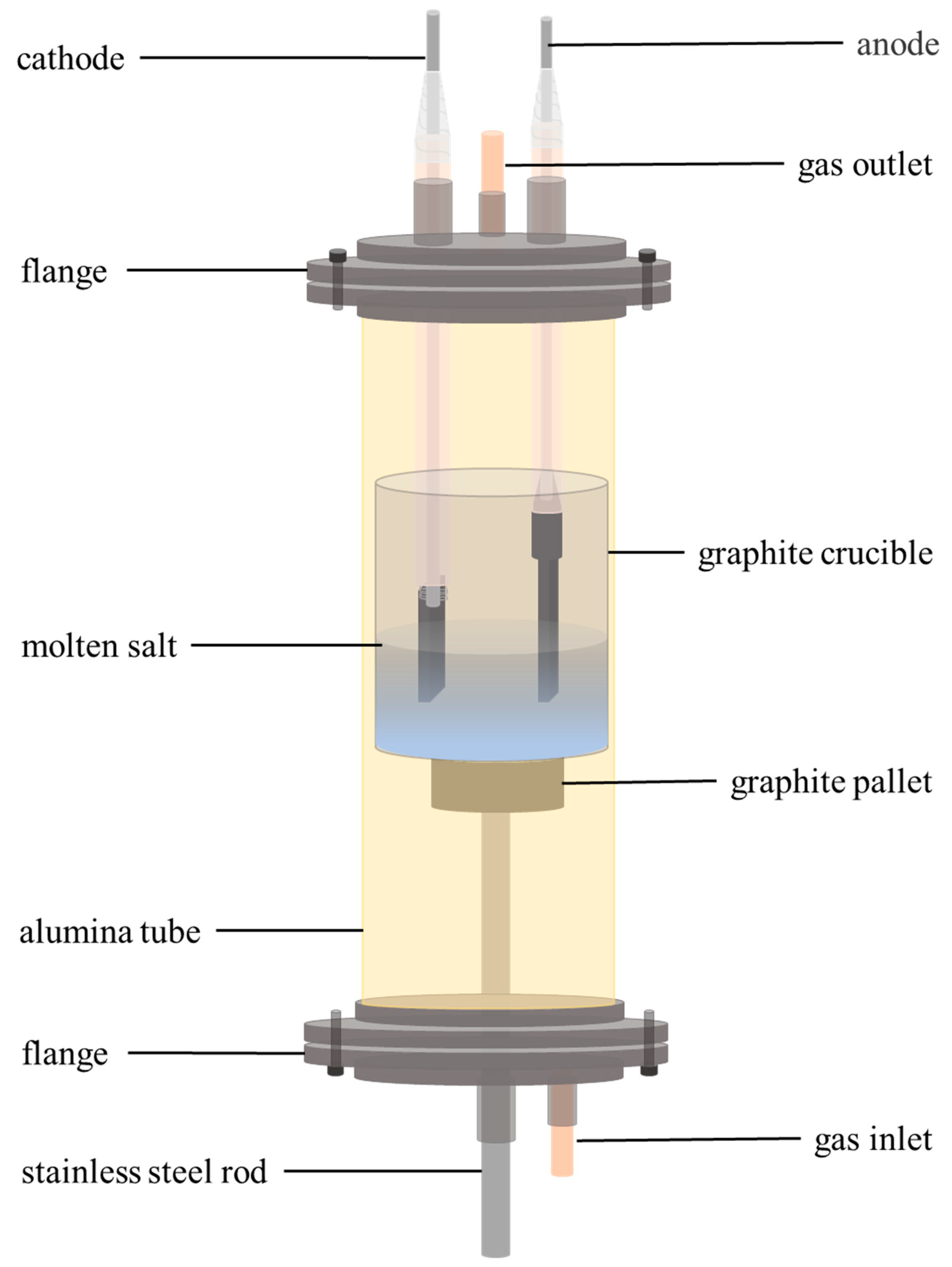
2.1. Raw Material and Experimental Setup

The raw materials used in the experiment are Na3AlF6 (≥99%, Sinopharm, Shanghai, China), NaF (≥99.5%, Aladdin, Shanghai, China), Al2O3 (≥99.95%, Aladdin, Shanghai, China), and MoO3 (≥99.95%, Shanghai, China). They were kept in a drying oven at 200 °C for 48 h to remove surface moisture before use. During the electroplating process, a two-electrode system was applied. The anode was a molybdenum sheet (8 × 3 × 50 mm) (≥99.9%, Haoye, Xingtai, China). The cathode was a nickel sheet (4 × 1 × 25 mm) (≥99.9%, Shuanghua, Xingtai, China). The surface of the electrode was polished with fine sandpaper to mirror the surface, rinsed with acetone, and dried, and then the prepared electrode was connected to a molybdenum rod acting as a current collector.

2.2. Coating Operation

The experimental setup for the preparation of metallic molybdenum coatings by electrodeposition in Na3AlF6-NaF-Al2O3-MoO3 system is shown in Figure 1. Na3AlF6 and NaF were added into the graphite crucible at a mole ratio of 21:79 and then heated to 930 °C and melted in the vertical electric resistance furnace. Then, MoO3 and Al2O3 were added into the Na3AlF6-NaF molten salts with a content of 5 mol % and 0.015 mol %, respectively. The electrodes were inserted into the molten salts and pre-electrolysis experiments were carried out at a current density of 110 mA·cm−2 for 2.8 h to remove impurity elements from the molten salts. After the pre-electrolysis, the effects of current density (10 mA·cm−2, 30 mA·cm−2, 50 mA·cm−2, and 70 mA·cm−2) and electrolysis time (10 min, 20 min, 30 min, and 60 min) on the morphology of the prepared molybdenum coatings on nickel substrates were studied in Na3AlF6-NaF-Al2O3-MoO3 system. Subsequently, electrodeposition was performed at current densities of 100 mA·cm−2 and 300 mA·cm−2 for 3 h and 1 h, respectively, to produce thick molybdenum coatings at higher current densities and longer electrolysis time. All the electrodeposition experiments were performed under an argon atmosphere. A DC power supply (HLR-3660D, Henghui, Shenzhen, China) was used to perform the galvanostatic control.

2.3. Characterization

After the electrodeposition experiment, the coated nickel substrates were removed and cooled, cleaned ultrasonically in deionized water for 10 min, then rinsed and soaked in acetone to remove the surface water, dried, and weighed. The surface and cross-section morphologies of the molybdenum metal coatings were examined using scanning electron microscopy equipped with energy dispersive spectroscopy (SEM-EDS, JSM-6510LV, JEOL, Tokyo, Japan). X-ray diffraction (XRD, Smart Lab, Rigaku, Tokyo, Japan. voltage: 40 kV, current: 40 mA, scan rate: 10°/min) was used to identify the phase composition of deposits on nickel substrates. After the electrolysis, the cathode current efficiency (η) was calculated by the following equation:
η = m q I t × 100 %
where m is the mass of molybdenum coatings, q is the electrochemical equivalent, I is the cathode current, and t is the electrolysis time.

3. Results and Discussion

In the Na3AlF6-NaF-Al2O3-MoO3 system at 930 °C, electrolysis was carried out at a cathode current density of 30 mA·cm−2 for 60 min, with the photograph of the produced coating with metallic luster shown in the top-left of Figure 2a, which was identified as molybdenum from the XRD results in Figure 2a. The surface morphology of the molybdenum coating is shown in Figure 2b, which was flat and uniform. And the EDS analysis (bottom-right of Figure 2b) revealed the high purity of the produced molybdenum coating.

3.1. Effect of Current Densities on Molybdenum Coatings

The effect of current density (10~70 mA·cm−2) on the produced molybdenum coatings was studied, and the surface morphologies are shown in Figure 3.
At the current density of 10 mA·cm−2, the grains on the surface of the molybdenum coating were relatively fine. As the current density increased to 30 and 50 mA·cm−2, the grain size became larger and more uniform, and the grain bonding was compact without voids and holes. When the current density reached 70 mA·cm−2, there were obvious coarse grains on the surface of the deposition layer with decreased flatness. There were voids between the grains and a few holes on the grain surface. Therefore, from the observation results of the surface morphology of the deposited molybdenum coating shown in Figure 3, when the current density was small, better uniformity and flatness of the surface were presented.
According to the basic principle of electrochemical deposition, when the current density is small, the low energy supply for the nucleation and growth results in low nucleation and grain growth rates. Thus, the formed coating is compact and relatively flat, which corresponds to the surface morphologies of produced molybdenum coatings at current densities from 10 to 30 mA cm−2. When the current density increases to 70 mA·cm−2, it is more prominent that the rate of grain growth at certain locations on the molybdenum coating surface exceeds that at other ones, resulting in preferential grain growth at these growth points, thus producing coarse grains. In addition, relatively rapid grain growth is accompanied by nucleation, resulting in voids on the surface, which reduces the flatness [27,28].
Subsequently, the cross-sectional morphologies of molybdenum coatings at different current densities were characterized by SEM, as shown in Figure 4.
From Figure 4, it can be seen that the molybdenum coatings prepared at different current densities were dense and tightly bonded to the nickel substrate. In addition, the thickness of the molybdenum coatings on the front and back sides of the nickel substrate was nearly the same. When the current density was 10 and 30 mA·cm−2, the molybdenum coating was dense and relatively flat with a thickness of 10 µm and 20 µm, respectively, free of cracks. As the current density increased to 50 and 70 mA·cm−2, the thickness of the molybdenum coating increased to 26 µm and 30 µm, respectively. The surface flatness of the molybdenum coating decreases, exhibiting an obviously hilly structure, mainly because the molybdenum atoms produced by electrodeposition grow preferentially on the protrusions of the grains when the current density increases, which makes the coating thickness at different locations not as uniform as that at low current densities [29]. These results agree with that of the dependence of the surface morphology of the molybdenum coating on the current density shown in Figure 3.
In summary, the prepared molybdenum coatings on nickel substrates were dense and coherent when the current density was between 10 and 70 mA·cm−2. The cathodic current efficiencies for preparation of them under these current densities were calculated to be above 97%. This indicates that the current density in this range almost has no impact on the current efficiency.
It has been reported that in KF-based molten salts for electroplating of molybdenum coating [20,23], as shown in Table 1, the cathode current efficiency was dramatically reduced to below 80% at a current density of around 70 mA·cm−2 due to the formation of dendrites and black powder. In the present investigation, when the current density was at 70 mA·cm−2, the current efficiency was similar to that under 10~50 mA·cm−2, which was above 97%. Therefore, it is assumed that the employment of higher current density might be available for producing molybdenum coatings in Na3AlF6-NaF-Al2O3-MoO3 system with an acceptable coating quality and current efficiency.

3.2. Effect of Electrodeposition Time on Molybdenum Coating

The effects of different electrodeposition times on the surface morphology of molybdenum coatings at a current density of 30 mA·cm−2 in the Na3AlF6-NaF-Al2O3-MoO3 system were investigated at 930 °C. The SEM images are shown in Figure 5.
When the electrodeposition time was 10 min, some parts of the nickel substrate surface were not covered by molybdenum. The molybdenum grains were fine, and there were still gaps between the grains. When the electrodeposition time was 20 min and 30 min, the molybdenum coating almost covered the whole nickel substrate surface, and the molybdenum grain size became larger, with a fibrous morphology. As the electrodeposition time was increased to 60 min, the molybdenum coating completely covered the nickel substrate. The surface was compact and consisted of well-developed polyhedral molybdenum grains with larger sizes.
The growth of electrodeposited coatings is an electrochemical crystallization process. At the beginning of electrodeposition, nuclei are generated, and the rate of nuclei generation is faster than that of grain growth, resulting in fine and loose grains being observed on the coating surface. Increasing the electrodeposition time, the grain growth rate is gradually accelerated, and the grain size becomes larger, but it is not enough to fill all the inter-grain gaps. As the electrodeposition time is further increased, the grain growth rate is higher than the nuclei generation rate, which makes the grains fully grow up. As a result, the inter-grain gaps disappear and the polyhedral crystals are well developed, forming a dense coating [30].
Compared with the electroplating of molybdenum coating in a molten KF-MoO3 system [23], it is found that the molybdenum grains obtained in the early stage of electrodeposition in the present molten system are very small in size, the nucleation rate is more rapid and the grain growth rate is slower, so the number of crystals is high. At a similar current density of around 30 mA·cm−2 under the electroplating for the same duration of 60 min, in the present investigation molybdenum coatings with more uniform distribution of grain size could be produced than that in KF-MoO3 melt. This makes it possible to produce a dense molybdenum coating even with longer electrodeposition time (i.e., more than 60 min) in Na3AlF6-NaF-Al2O3-MoO3 molten salts.

3.3. Preparation of Thick Molybdenum Coating

Based on the above results and discussion, it is assumed that it could be possible to increase the current density and electrodeposition time to produce molybdenum coatings with increased thickness in a molten Na3AlF6-NaF-Al2O3-MoO3 system. Therefore, electrodeposition was carried out at a current density of 100 mA·cm−2 for 3 h at 930 °C to prepare thick molybdenum coatings on a nickel sheet and wire, respectively, and the corresponding photographs and SEM images of the deposits are presented in Figure 6.
Figure 6a,c shows the photographs of molybdenum coating deposited on a nickel sheet and wire, respectively, demonstrating a distinct metallic luster. Typical SEM observation of them, as demonstrated in Figure 6b,d, revealed that both surfaces were dense and relatively flat, with relatively uniform grain size distribution.
Figure 7 demonstrates the cross-section of the electroplated molybdenum coating on the nickel sheet and wire. It can be seen that they were relatively flat, uniform, and dense, with good adhesion to the nickel substrate. Their thicknesses were 125 and 140 µm, respectively, and there was no significant difference between the thicknesses on the front and back sides for nickel sheets. The cathodic current efficiency was calculated to be 79.8% and 85.9%, respectively.
Furthermore, the electroplating of thick molybdenum coating under a higher current density (300 mA·cm−2) was carried out in Na3AlF6-NaF-Al2O3-MoO3 melt for 1 h at 930 °C. The SEM images of the surface and cross-section of the produced coating are presented in Figure 8.
As shown in Figure 8a, the surface of the molybdenum coating was dense with coarser grains. In Figure 8b, the coating was dense and closely bonded with the substrate with a thickness of 100 µm. And the cathode current efficiency of the electrodeposition process was calculated as 72.4%, which is lower than that at 100 mA·cm−2 for 3 h. This may be due to the possible formation of dendrites, ascribed to more serious concentration polarization at such high cathode current density.
Therefore, in the Na3AlF6-NaF-Al2O3-MoO3 system, it is suggested that at a current density of less than 100 mA·cm−2, a dense, coherent, and adhesive molybdenum coating with a larger thickness (more than 150 µm) could be produced with longer electrodeposition duration under an acceptable cathode current efficiency.

4. Conclusions

The electrodeposition of molybdenum coatings was carried out in a Na3AlF6-NaF-Al2O3-MoO3 molten salt system at 930 °C at different current densities and electrodeposition times. Dense, coherent, and relatively flat molybdenum coatings were prepared on nickel substrates. With the increase of current density (10~70 mA·cm−2), the thickness of the molybdenum coating was increased from 10 µm to 30 µm. Under all the current densities, the coatings were compact and coherent, with a current efficiency of more than 97%.
At a current density of 30 mA·cm−2, with the increase of electrodeposition time (10~60 min), it was found that at the initial stage of electrodeposition, the formation of a large amount of fine molybdenum crystals results in maintaining relatively small crystals even at 60 min, ensuring the flatness and uniformity of the produced coating. The morphology of the deposits changed from fine, fibrous to well-developed faceted crystals.
Molybdenum coatings with a thickness of 125 µm and 140 µm were obtained on a nickel sheet and wire, respectively, at a current density of 100 mA·cm−2 for 3 h of electrodeposition. The current efficiency was calculated to be 79.8% and 85.9%. The coatings were dense, uniform, and relatively flat. At a current density of 300 mA·cm−2, a thick and dense molybdenum coating was also obtained by electrodeposition for 1 h, with a lower current efficiency of 72.4%.

Author Contributions

Q.K.: Have made substantial contributions to the conception, acquisition, analysis, and interpretation of data for the work, drafting the work. Agreement to be accountable for all aspects of the work in ensuring that questions related to the accuracy or integrity of any part of the work are appropriately investigated and resolved. W.J.: Analysis of data for the work; C.G.: Interpretation of data for the work; J.P.: Interpretation of data for the work; J.Z.: Revising it critically for important intellectual content; G.M.H.: Final approval of the version to be published; S.X.: Final approval of the version to be published. Agreement to be accountable for all aspects of the work in ensuring that questions related to the accuracy or integrity of any part of the work are appropriately investigated and resolved. P.W.: Final approval of the version to be published. All authors have read and agreed to the published version of the manuscript.

Funding

This research received no external funding.

Institutional Review Board Statement

Not applicable.

Informed Consent Statement

Not applicable.

Data Availability Statement

Not applicable.

Conflicts of Interest

The authors declare no conflict of interest.

References

  1. Xiang, T.G. Molybdenum Metallurgy; Central South University Press: Changsha, China, 2002. [Google Scholar]
  2. Xu, K.D. Material Science and Engineering of Molybdenum; Metallurgical Industry Press: Beijing, China, 2014. [Google Scholar]
  3. Hwanga, B.; Jehoon, A.; Lee, S. Effects of blending elements on wear resistance of plasma-sprayed molybdenum blend coatings used for automotive synchronizer rings. Surf. Coat. Technol. 2005, 194, 256–264. [Google Scholar] [CrossRef]
  4. Koyama, K.; Hashimoto, Y.; Terawaki, K. Smooth electrodeposits of molybdenum from KF-K2B4O7-K2MoO4 fused salt melts. J. Less Common Met. 1987, 134, 141–151. [Google Scholar] [CrossRef]
  5. Koyama, K.; Hashimoto, Y.; Omori, S.; Terawaki, K. Electrodeposition of molybdenum in KF-Na2B4O7-K2MoO4 fused salts. Trans. Jpn. Inst. Met. 1984, 25, 265–275. [Google Scholar] [CrossRef] [Green Version]
  6. Babu, M.V.; Kumar, R.K.; Prabhakar, O.; Shankar, N.G. Simultaneous optimization of flame spraying process parameters for high quality Mo coatings using Taguchi methods. Surf. Coat. Technol. 1996, 79, 276–288. [Google Scholar] [CrossRef]
  7. Vaidya, A.; Streibl, T.; Li, L.; Sampath, S.; Kovarik, O.; Greenlaw, R. An integrated study of thermal spray process-structure-property correlations: A case study for plasma sprayed Mo coatings. MSEA 2005, 403, 191–204. [Google Scholar] [CrossRef]
  8. Jin, G.; Xu, B.S.; Wang, H.D.; Li, Q.F.; Wei, S.C. Tribological properties of molybdenum coatings sprayed by electro-thermal explosion directional spraying. Surf. Coat. Technol. 2007, 201, 6678–6680. [Google Scholar] [CrossRef]
  9. Khan, A.A.; Labbe, J.C.; Grimaud, A.; Fauchais, P. Molybdenum and tungsten coatings for x-ray targets obtained through the low-pressure plasma spraying process. J. Therm. Spray Technol. 1997, 6, 228–234. [Google Scholar] [CrossRef]
  10. Wlodek, S.T.; Wulff, J. The adhesion of vapor-deposited Mo coatings. J. Electrochem. Soc. 1960, 107, 565. [Google Scholar] [CrossRef]
  11. Fukutomi, M.; Okada, M.; Watanabe, R. Molybdenum coating of vanadium by chemical vapor deposition. J. Less Common Met. 1976, 48, 65–77. [Google Scholar] [CrossRef]
  12. Hasan, S.N.; Xu, M.; Asselin, E. Electrodeposition of metallic molybdenum and its alloys—A review. Can. Met. Q. 2019, 58, 1–18. [Google Scholar] [CrossRef]
  13. Senderoff, S.; Brenner, A. The electrolytic preparation of molybdenum from fused salts. I. Electrolytic studies. J. Electrochem. Soc. 1954, 101, 16. [Google Scholar] [CrossRef]
  14. Kipouros, G.J.; Sadoway, D.R. The electrodeposition of improved Mo coatings from molten salts by the use of electrolyte additives. J. Appl. Electrochem. 1988, 18, 823–830. [Google Scholar] [CrossRef]
  15. Ene, N.; Donath, C. Texture of electrolytic Mo deposition from molten alkali halide. J. Optoelectron. Adv. Mater. 2006, 8, 708. [Google Scholar]
  16. Senderoff, S.; Mellors, G.W. Electrodeposition of coherent deposits of refractory metals: V. Mechanism for the Deposition of Molybdenum from a Chloride Melt. J. Electrochem. Soc. 1967, 114, 556. [Google Scholar] [CrossRef]
  17. Babushkina, O.; Voyiatzis, G.; Østvold, T. Raman and infrared spectroscopic studies of (NaF-KF)-K2MoO2-B2O3 melts and the mechanism of electrodeposition of molybdenum. Anal. Chim. Acta 1999, 53, 320–328. [Google Scholar]
  18. Silný, A.; Daněk, V.; Chrenková, M. Mechanism of the molybdenum electrodeposition from molten salts. In Refractory Metals in Molten Salts: Their Chemistry, Electrochemistry and Technology; Springer Netherlands Press: Berlin, Germany, 1998; Volume 53, pp. 183–187. [Google Scholar]
  19. Terawaki, K.; Koyama, K.; Hashimoto, Y.; Omori, S. Electrodeposition of molybdenum in KF-B2O3-MoO3 fused salts. J. Jpn. Inst. Met. 1986, 50, 303–307. [Google Scholar] [CrossRef] [Green Version]
  20. Zatko, P.; Makyta, M.; Sykorova, J.; Silny, A. Electrodeposition of molybdenum from KF-K2MoO4-SiO2 Melts. Chem. Pap. 1994, 48, 10–14. [Google Scholar]
  21. McCawley, F.X.; Wyche, C.; Schlain, D. Electrodeposition of molybdenum coatings. J. Electrochem. Soc. 1969, 116, 1028. [Google Scholar] [CrossRef]
  22. Kolosov, V.N.; Karpenko, O.A.; Gel’, R.P.; Drobotenko, G.A.; Shevyrev, A.A. Electrodeposition of high-purity molybdenum coatings on nickel. Inorg. Mater. 2001, 37, 1263–1269. [Google Scholar] [CrossRef]
  23. Jin, W.; Ge, C.; Kou, Q.; Jiang, P.; Xiao, S. Electrochemical preparation of Mo coatings on nickel from KF-MoO3 melts. Int. J. Electrochem. Sci. 2021, 16, 210311. [Google Scholar] [CrossRef]
  24. Makyta, M.; Zatko, P.; Bezdicka, P. Electrodeposition of molybdenum from molten salts. Chem. Pap. 1993, 47, 28–31. [Google Scholar]
  25. Malyshev, V.V. Theoretical foundations and practical realization of molybdenum electrodeposition in ionic melts. Theor. Found. Chem. Eng. 2007, 41, 284–299. [Google Scholar] [CrossRef]
  26. Wu, X.Y.; Bai, S.X.; Wang, Z.; Hu, L.A.; Ye, Y.C.; Li, S.; Tang, Y. Research Progress of Molybdenum Coating Prepared by Electrodeposition. Rare Met. 2023, 51, 39–48. [Google Scholar]
  27. Yang, P.X.; An, M.Z.; Su, C.N.; Wang, F.P. Electrodeposition behaviors of pure cobalt in ionic liquid. Acta Phys.-Chim. Sin. 2008, 24, 2032–2036. [Google Scholar]
  28. Chung, C.K.; Chang, W.T. Effect of pulse frequency and current density on anomalous composition and nanomechanical property of electrodeposited Ni-Co films. Thin Solid Films 2009, 517, 4800–4804. [Google Scholar] [CrossRef]
  29. Jiang, F.; Zhang, Y.; Sun, N.; Liu, Z. Effect of direct current density on microstructure of tungsten coating electroplated from Na2WO4-WO3-NaPO3 system. Appl. Surf. Sci. 2014, 317, 867–874. [Google Scholar] [CrossRef]
  30. Abyaneh, M.Y. Calculation of overlap for nucleation and three-dimensional growth of centres. Electrochim. Acta 1982, 27, 1329–1334. [Google Scholar] [CrossRef]
Figure 1. Schematic diagram of the experimental setup for the preparation of metallic molybdenum coatings by electrodeposition in Na3AlF6-NaF-Al2O3-MoO3 salts at 930 °C.
Coatings 13 01266 g001
Figure 2. The appearance, XRD patterns (a), and SEM-EDS (b) of molybdenum coating obtained in Na3AlF6-NaF-Al2O3-MoO3 system by constant current electrolysis for 60 min at a current density of 30 mA·cm−2 at 930 °C.
Coatings 13 01266 g002
Figure 3. SEM images of the surface morphology of molybdenum coatings prepared by electrodeposition in Na3AlF6-NaF-Al2O3-MoO3 system at 930° C for 60 min at different current densities ((a). 10 mA·cm−2; (b). 30 mA·cm−2; (c). 50 mA·cm−2; (d). 70 mA·cm−2).
Coatings 13 01266 g003
Figure 4. SEM images of cross sections of molybdenum coatings prepared by electrodeposition in Na3AlF6-NaF-Al2O3-MoO3 system at 930 °C for 60 min at different current densities ((a). 10 mA·cm−2; (b). 30 mA·cm−2; (c). 50 mA·cm−2; (d). 70 mA·cm−2).
Coatings 13 01266 g004
Figure 5. SEM images of the surface morphology of molybdenum coating prepared by different electrodeposition times in Na3AlF6-NaF-Al2O3-MoO3 system at 930 °C with a current density of 30 mA·cm−2 ((a). 10 min; (b). 20 min; (c). 30 min; (d). 60 min).
Coatings 13 01266 g005
Figure 6. Appearance and SEM images of molybdenum coating prepared by electrodeposition in Na3AlF6-NaF-Al2O3-MoO3 system at a current density of 100 mA·cm−2 for 3 h at 930 °C ((a,b). nickel sheet; (c,d). nickel wire).
Coatings 13 01266 g006
Figure 7. Cross-sectional SEM images of molybdenum coatings prepared by electrodeposition in Na3AlF6-NaF-Al2O3-MoO3 system at a current density of 100 mA·cm−2 for 3 h at 930 °C ((a). nickel sheet; (b). nickel wire; top-left insets, low and middle magnification images).
Coatings 13 01266 g007
Figure 8. SEM images of the surface (a) and cross-section (b) of molybdenum coating prepared by electrodeposition at a current density of 300 mA·cm−2 for 1 h in Na3AlF6-NaF-Al2O3-MoO3 system at 930 °C.
Coatings 13 01266 g008
Table 1. Comparison of different systems for electrodeposition of molybdenum.
SystemCurrent Density (mA·cm−2)Cathode Current Efficiency (%)Visual Evaluation
KF (85 mol %)-K2MoO4 (10 mol %)-SiO2 (5 mol %) [20]7.398.3Smooth deposit
15.698.5Smooth deposit
29.392.5Smooth deposit
4490.6Smooth deposit, dendrites
63.377Smooth deposit,
Black powder
87.924.8Black powder
146.624.5Black powder
KF-MoO3 (95:5 mol %) [23]1192.5Smooth deposit
3391Smooth deposit
5579Smooth deposit
7773Smooth deposit, dendrites
Na3AlF6-NaF (21:79 mol%)-Al2O3 (0.015 mol %)-MoO3 (5 mol %)1097Smooth deposit
3097Smooth deposit
5097Smooth deposit
7097Smooth deposit
Disclaimer/Publisher’s Note: The statements, opinions and data contained in all publications are solely those of the individual author(s) and contributor(s) and not of MDPI and/or the editor(s). MDPI and/or the editor(s) disclaim responsibility for any injury to people or property resulting from any ideas, methods, instructions or products referred to in the content.

