Article

Experimental Study on the Corrosion of Fulvic Acid to Cement-Soil and Its Microstructures in the Peat Soil Environment

1
Faculty of Civil Engineering and Mechanics, Kunming University of Science and Technology, Kunming 650500, China
2
Yunnan Key Laboratory of Geotechnical Engineering and Geohazards, Kunming 650051, China
3
Kunming Survey Design and Research Institute Co., Ltd. of CREEC, Kunming 650200, China
*
Author to whom correspondence should be addressed.
Coatings 2023, 13(8), 1366; https://doi.org/10.3390/coatings13081366
Submission received: 17 June 2023 / Revised: 1 August 2023 / Accepted: 1 August 2023 / Published: 3 August 2023
(This article belongs to the Section Corrosion, Wear and Erosion)

Abstract

:
In underground engineering, cement-soil reinforcement beneath a peat soil environment is a significant challenge. To investigate the corrosiveness of fulvic acid on cement-soil and its micro and fine structure changes under the peat soil environment (PSE), an experiment was conducted to prepare peat soil by mixing humic acid (HA) into an alluvial clayey soil and then adding cement to make a cement-soil specimen, which was soaked in a fulvic acid (FA) solution and deionized water to simulate the different working of the cement-soil. The experiment was carried out by a scanning electron microscopy (SEM) test, mercury intrusion porosimetry (MIP) test, pore (particle) and fracture image recognition and analysis (PCAS), and unconfined compressive strength (UCS) test on cement-soil with soaking time as the variation factor. The results show that: In the deionized water environment, the structural characteristics of the cement-soil exhibited a gradual enhancement followed by a slight weakening. Conversely, when placed in a peat soil environment, the strength of the cement-soil initially increased at a slow rate due to the gelling and filling impact of fulvic acid. However, in the later stages, the corrosive influence of fulvic acid became dominant. This led to an enlargement of the pore space within the cement-soil, resulting in a gradual deterioration of its structure. Consequently, the strength of the cement-soil displayed a pattern of slow initial increase followed by a rapid decrease.

1. Introduction

The region surrounding Dianchi Lake and Erhai Lake in Yunnan is an ancient lake and marsh region. Its geographical location and climate are extremely unique. Consequently, peat soil is abundant in this region. Due to its high organic matter content, large lacuna ratio, high compressibility, high water content, and low bearing capacity, peat soil is classified as poor foundation soil [1,2,3]. Prior research has used cement to solidify it to improve the bearing capacity of peat soil, resulting in significant improvements in the field [4,5,6,7]. Nonetheless, the cement-soil created by cement solidification still exists in the PSE. Many humic groups contribute to the environment’s acidity. This environment will cause the cement-soil to corrode, disintegrate, and utterly lose its bearing capacity [8]. Therefore, the change in cement-soil’s strength is closely related to the microstructure’s change after corrosion. In addition, according to previous studies on the existing forms and solubility differences of humic acids (HA and FA) in peat soil, fulvic acid is soluble in alkaline solution, water, and acid solution, and it exists in the soil in liquid form;humic acid is soluble in alkaline solution but insoluble in water and acid solution, and it exists as solid particles [9]. In order to provide theoretical support for the corrosion resistance of cement-soil, it is essential to explore the corrosion of fulvic acid on cement-soil and its microstructural alterations under the PSE.
The examination of the microstructure frequently employs sophisticated instruments and well-established technical methodologies. One notable development in the field of material science is the invention of scanning electron microscopy (SEM), which has significantly enhanced the ability to investigate microstructural characteristics of various materials. This technique is employed to examine the internal micro-area morphology of soil and its solidified material, hence offering compelling evidence regarding the alteration of the sample’s internal structure. In 2018, Howayek et al. [10] used SEM combined with EDX to analyze the samples, finding a carbonate cladding layer between clay particles and the carbon bridge connected to the clay particles. In 2019, Yao et al. [11] analyzed the change in the microstructure of cement-soil by SEM test. SEM shows that adding nano-MgO can make the cement-soil structure uniform and dense, but when the amount of nano-MgO is high, the cement-soil will expand and produce cracks. Sulfuric acid erosion will destroy the structure of cement-soil, and the formation of ettringite will deform the structure of cement-soil. In 2021, Ruan et al. [12] used polypropylene fiber to improve the mechanical properties of cement mortar soil and observed the microstructure changes of cement-soil. SEM shows needle-like, layered, and flocculent hydration products in cement-soil. It shows that when there is enough free water and room for development in the cement-soil, flocculated hydration products will appear to fill the pores. In 2021, Jiang et al. [13] observed the microstructure of cement-soil by SEM, which showed that hydrated cement formed calcium silicate gel, acicular ettringite, and hexagonal calcium hydroxide crystal. In 2021, Chen et al. [14] observed the microstructure of cemented mucky soil samples by SEM. The results show that with the increase in curing time, the cement hydration products closely connect the soil particles and change the structure of cement-soil, but the smooth surface formed can easily cause the mutual slip between the cementitious products. After the curing time reached 90d, the curing effect gradually deteriorated. In 2022, Chen et al. [15] observed the microstructure of cement-soil mixed with or not mixed with nano-SiO2 in a seawater environment by SEM test. The results show that the cement-soil not mixed with nano-SiO2 becomes very loose under seawater erosion, with more pores, small cracks, and poor structure. The cement-soil mixed with nano-SiO2 becomes compact, does not have apparent pores, and has a better structure. However, SEM can only qualitatively or semi-quantitatively analyze pore changes. Therefore, many researchers used mercury intrusion porosimetry (MIP) to quantitatively analyze the pores and distribution characteristics of the sample to study the changes in the microstructure of cement-soil quantitatively. For example, Hu et al. [16] drew the pore size distribution curve of cement solidified sludge by MIP test in 2016. The results show that when the curing effect is poor, the silt cement-soil produces shrinkage deformation, and the pore size distribution of cement-soil changes due to the filling effect of hydration products. In 2017, Qu et al. [17] used the MIP test to study the permeability of silty clay solidified by cement and other curing agents. The curing agent makes the pores of cement-soil transform from large pores to small pores; the pore volume gradually decreases, and the permeability coefficient of cement-soil gradually decreases. In 2018, Bozbey [18] used MIP and SEM to study the microstructure changes of lime-stabilized clay. The results show that lime changes the microstructure of clay by reducing pores. Although the pore size and porosity increase in the short term, the pore size decreases, and the porosity decreases significantly after one year of curing time. In 2021, Chen et al. [19] studied the development of the pore structure of cement paste by MIP and nitrogen adsorption. The results of MIP show that hydration products of cement can fill part of the pore and reduce pore volume. In 2023, Cao et al. [20] studied cement-soil by SEM test. The results show that HA consumes cement hydration products, but FA can fill the pores of cement-soil.
In summary, scholars and engineers frequently employ SEM and MIP to investigate the alterations in the microstructure of soil and its solidified byproducts, resulting in notable advancements in this field. However, there is a scarcity of research that integrates SEM and MIP for the purpose of analysis. Consequently, in this study, the cohesive soil was blended with HA to produce peat soil, which was subsequently combined with cement to create cement-soil specimens. The cement-soil was submerged in a solution of FA and deionized water in order to replicate various operational conditions experienced by cement-soil. Following the processes of soaking and corrosion, the cement-soil composite underwent a series of tests, including SEM, MIP, PCAS, and UCS tests. The experiments analyzed the alteration in the microstructure of cement-soil due to PSE corrosion, examining qualitative and quantitative features. The findings establish a theoretical foundation for understanding the corrosion resistance of cement-soil in the context of PSE.

2. Materials and Methods

2.1. Materials

The apparent conditions of the soil samples, cement, humic acid (HA) particles, and fulvic acid (FA) powder employed in the test are shown in Figure 1.
The basic situations of materials used in the test are as follows:
  • Test soil
The soil sample used in this study is derived from alluvial clayey soil collected from the northern slope of the Chenggong Campus dormitories at Kunming University of Science and Technology, located in Kunming, Yunnan Province. Table 1 displays the primary physical parameters of the soil samples. The cohesive soil that was acquired is subjected to grinding following natural air-drying. Subsequently, it is passed through a geotechnical sieve with a diameter of 2.00 mm. The resulting material is then placed into a storage container, which is sealed and preserved. The soil’s particle density (specific gravity) is recorded as 2.84 g·cm−3.
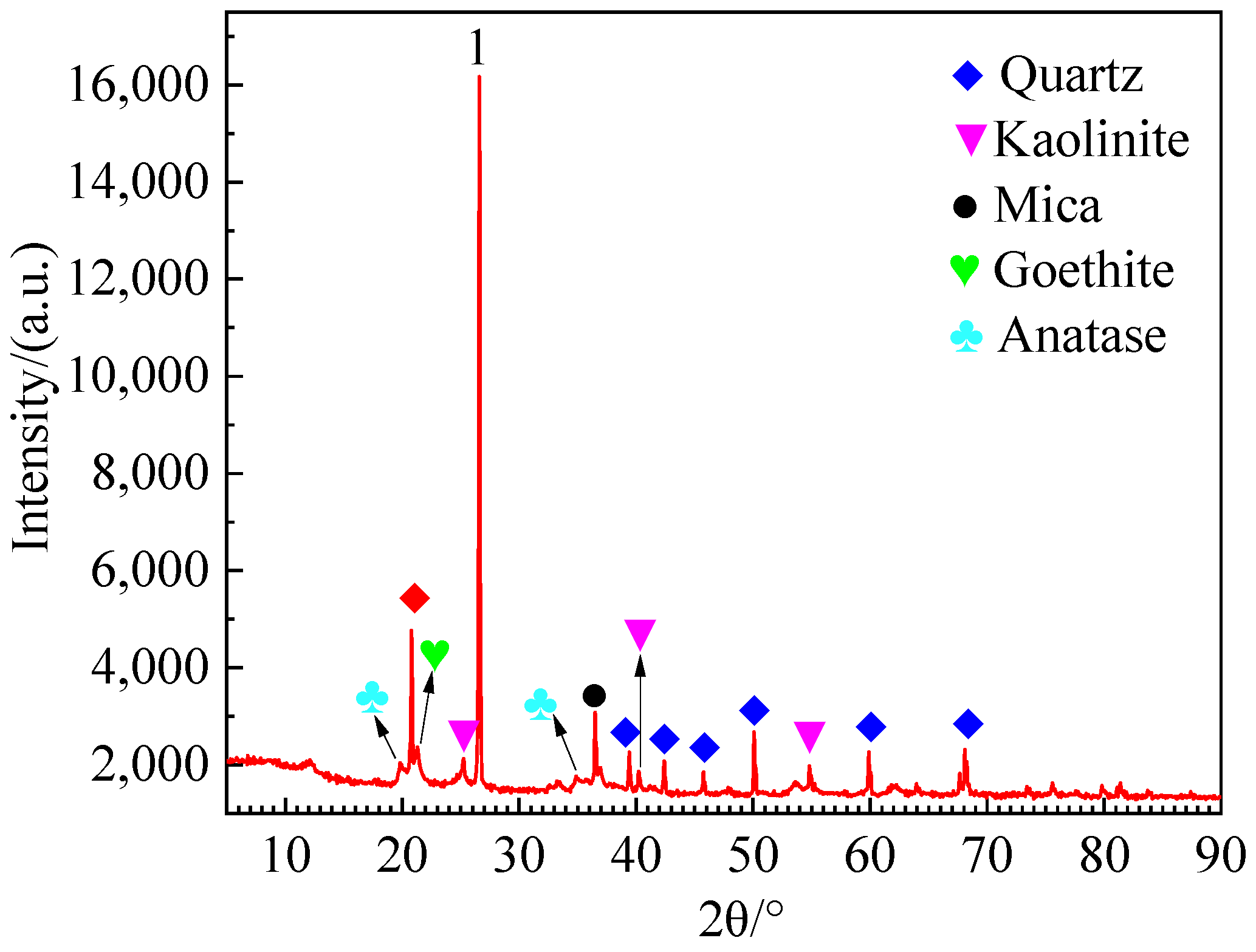
X-ray fluorescence (XRF) was employed to ascertain the chemical composition and mass fraction of each constituent in the soil. Table 2 displays the findings, revealing that the soil specimen’s primary chemical constituents were SiO2, Fe2O3, and Al2O3. The soil sample underwent X-ray diffraction analysis to ascertain its phase makeup. The findings are depicted in Figure 2. The primary constituents of the soil sample are quartz, kaolinite, mica, goethite, and anatase. The soil composition is characterized by its singularity, exhibiting a low concentration of organic materials. Hence, the utilization of soil as an experimental material to investigate the alterations in the microstructure of cement-soil under the corrosion of PSE yields minimal impact on the test outcomes.
2.
Cement
The cement chosen for this project is the regular Portland cement manufactured by Yunnan Huaxin Cement Co., Ltd., the cement company is located in Kunming, China. The strength rating of the material is 42.5 (label: PO42.5). The specific gravity of the cement particles was measured to be 3.1 g·cm−3.
3.
HA reagent
The Tianjin Guangfu Chemical Reagent Factory manufactured the humic acid reagent utilized in the experiment, the chemical reagent plant is located in Tianjin, China. The concentration of HA in the reagent was determined to be 41.68%, while its particle density (specific gravity) was 1.85 g·cm−3.
4.
FA reagent
The FA reagent utilized in the experiment is a biological FA reagent manufactured by Pingxiang Red Land Humic Group Co., Ltd., the humic group company is located in Pingxiang City, China. The concentration of FA in the reagent was determined to be 60%.
5.
Test water
The water being tested is deionized water.

2.2. Experimental Design and Sample Preparation

Based on the findings of previous research [21], it was observed that the peat soil surrounding Dianchi Lake and Erhai Lake exhibited a variation in the organic matter content, ranging from 10.73% to 75.09%. Furthermore, the total quantity of humic group compounds varied from 7.15% to 50.06%, while the concentration of humic acid (HA) ranged from 2.36% to 28.13%. To fit the engineering practice more effectively, the dosage of HA utilized in this experiment has been set at 20%, while the cement mixing ratio has been established at 20%. The cement-soil samples were submerged in a solution of fulvic acid (FA), with continuous addition of FA to maintain a consistent pH value of the solution, as well as in deionized water. The immersion duration of cement-soil specimens is established at intervals of 28 days, 90 days, 180 days, 270 days, and 365 days. In order to adhere to the sampling requirements and fundamental properties of peat soil, the moisture content (ω) and void ratio (e) of a peat soil sample were assessed and regulated. The moisture content was determined to be 24%, while the void ratio came out as 1.2. The experimental design is presented in Table 3.
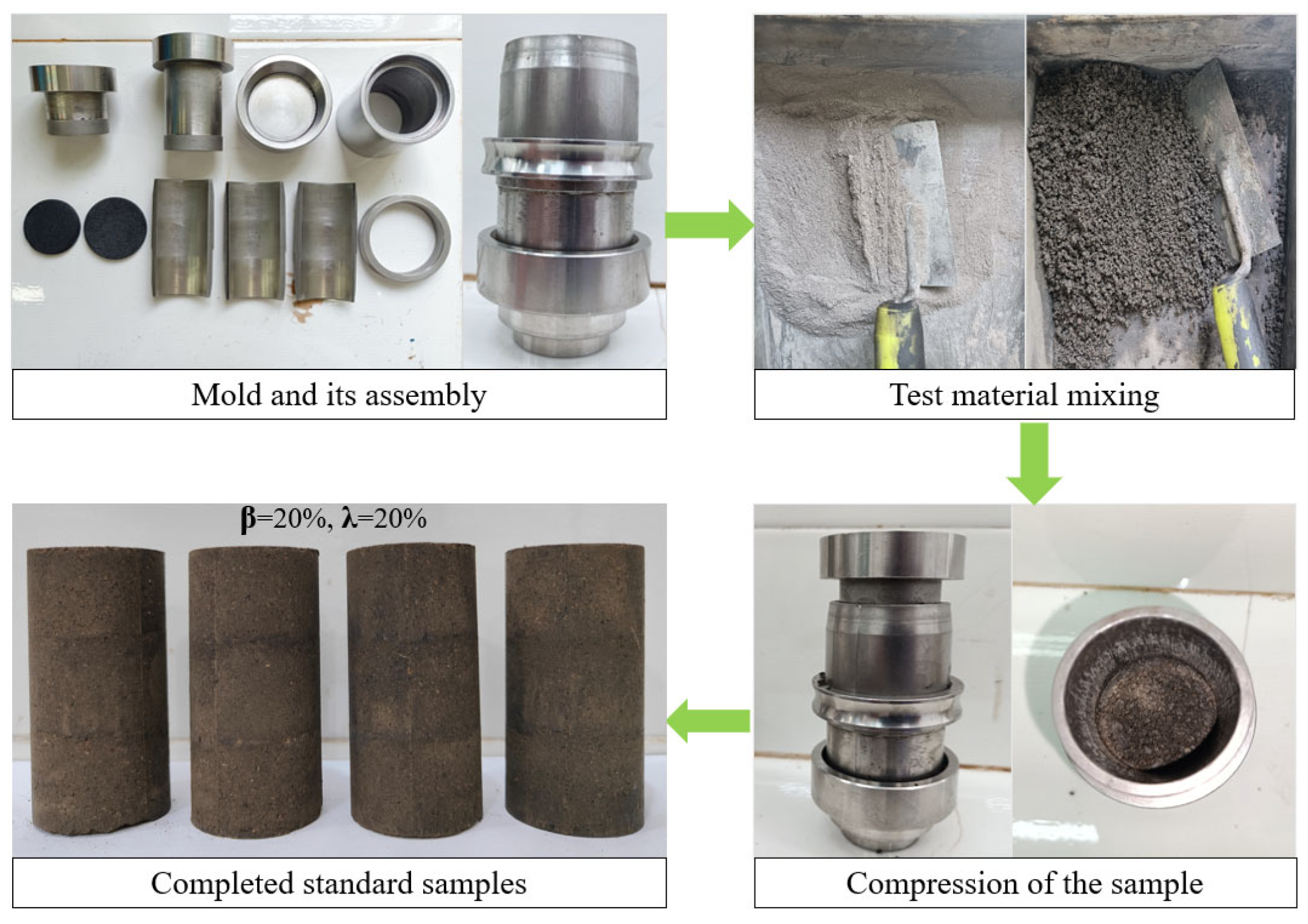
The preparation, maintenance, and soaking of the samples were conducted in accordance with the Standard for Geotechnical Testing Method (GB/T50123-2019) [22] and previous scholarly works [20]. The process in its entirety is illustrated in Figure 3.

2.3. Experimental Procedure

The samples in this study were exposed to several analytical techniques, including scanning electron microscopy (SEM), mercury intrusion porosimetry (MIP), pore (particle) and fracture image identification and analysis (PCAS), and unconfined compressive strength (UCS) testing. The test procedure may be outlined as follows:
  • SEM test
Based on the observed phenomena in the sample, the cement-soil may be categorized into three distinct layers: a strong wetting reaction layer (SWRL), a wetting reaction transition layer (WRTL), and a weak wetting reaction layer (WWRL) [20]. The SWRL, WWRL of cement-soil specimens soaked in fulvic acid solution (pH = 6), and cement-soil specimens soaked in deionized water were taken for the study.
A piece with a flat surface is excised during the preparation of the SEM test sample. Despite the surface seeming flat, there are no discernible cut lines, and it is not feasible to do any polishing treatment. Once the observation segment has been completed, it should not be touched and cleaned. Initially, the test block is treated to low-temperature drying within an oven, followed by vacuum drying. Subsequently, it is affixed onto a metal platform using conductive glue and coated with a layer of gold to augment its conductivity. Following the completion of the production process, the SEM test was conducted using the Czech VEGA3-TESCAN automated tungsten filament scanning electron microscope.
2.
MIP test
The MIP test was conducted on the specimen based on the experimental protocol. The test was conducted using the Mike AutoPore IV 9500 high-performance automated mercury porosimeter as the instrument.
3.
PCAS test
The PCAS test utilized SEM test pictures to conduct a semi-quantitative analysis of pores. The procedures for sample preparation and testing in the PCAS test were identical to those employed in SEM.
4.
UCS test
The cement-soil’s unconfined compressive strength (UCS) was tested using a lime-soil electromotive instrument tester. The instrument model under consideration is the YSH-2, which is manufactured by Nanjing Ningxi Soil Instrument Co., Ltd. (Nanjing, China). During the testing procedure, the rate of axial compression of the instrument is regulated at a constant value of 1.0 mm per minute. The samples undergo a continuous application of pressure until they reach the point of failure. The mean strength of the tested samples was determined as the samples’ unconfined compressive strength (UCS).

3. Results and Analysis

3.1. SEM Test Results and Analysis

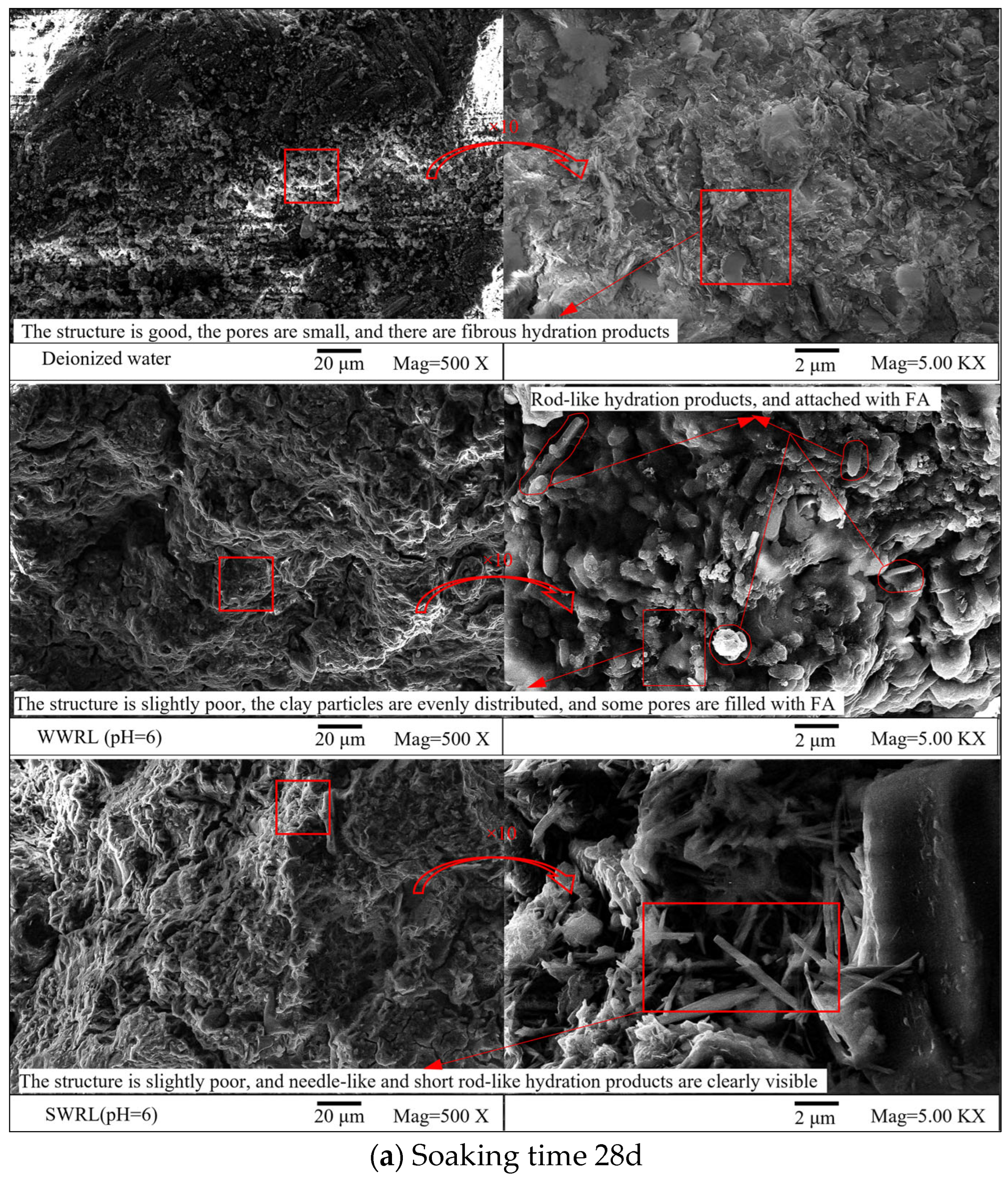
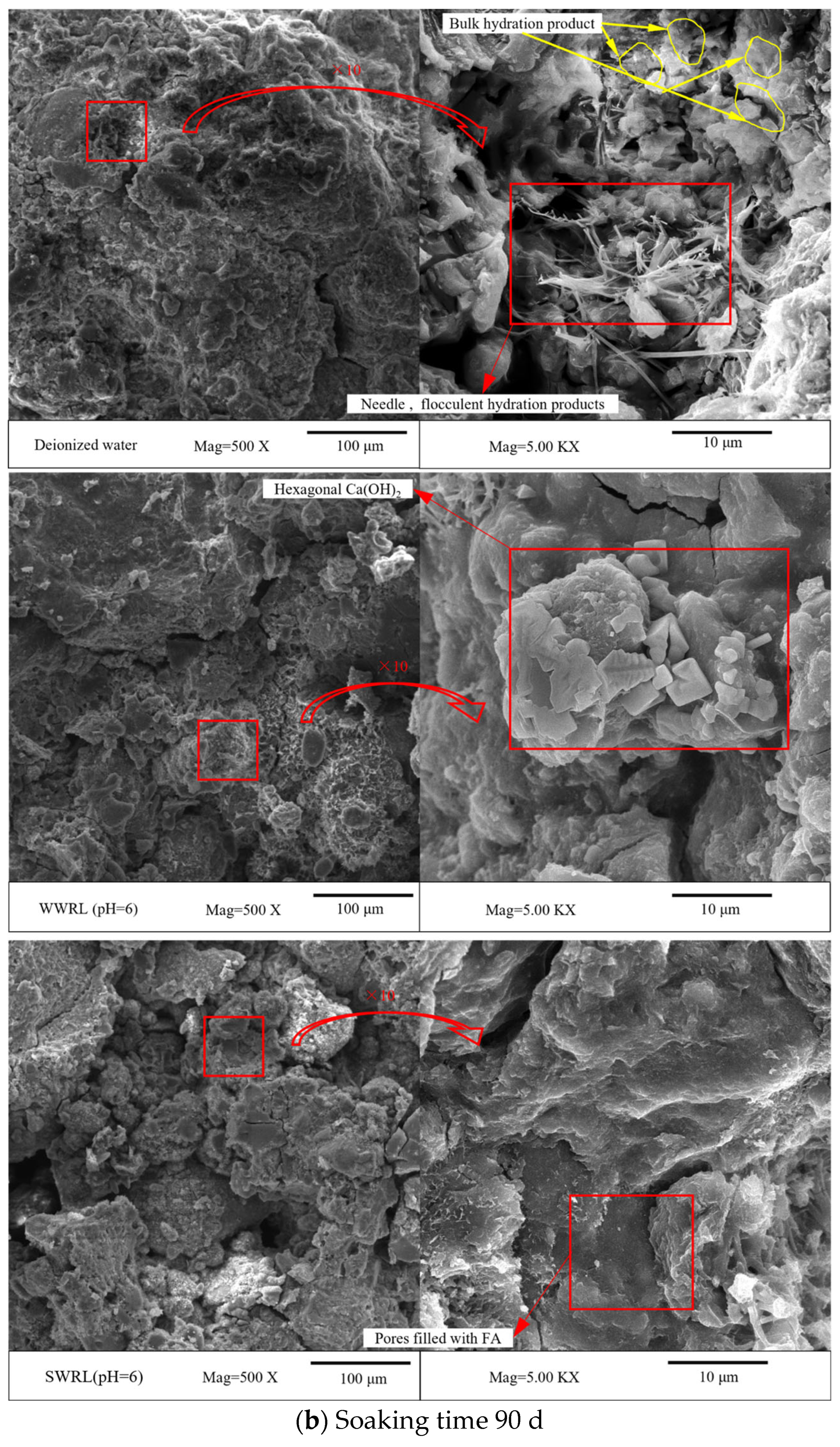
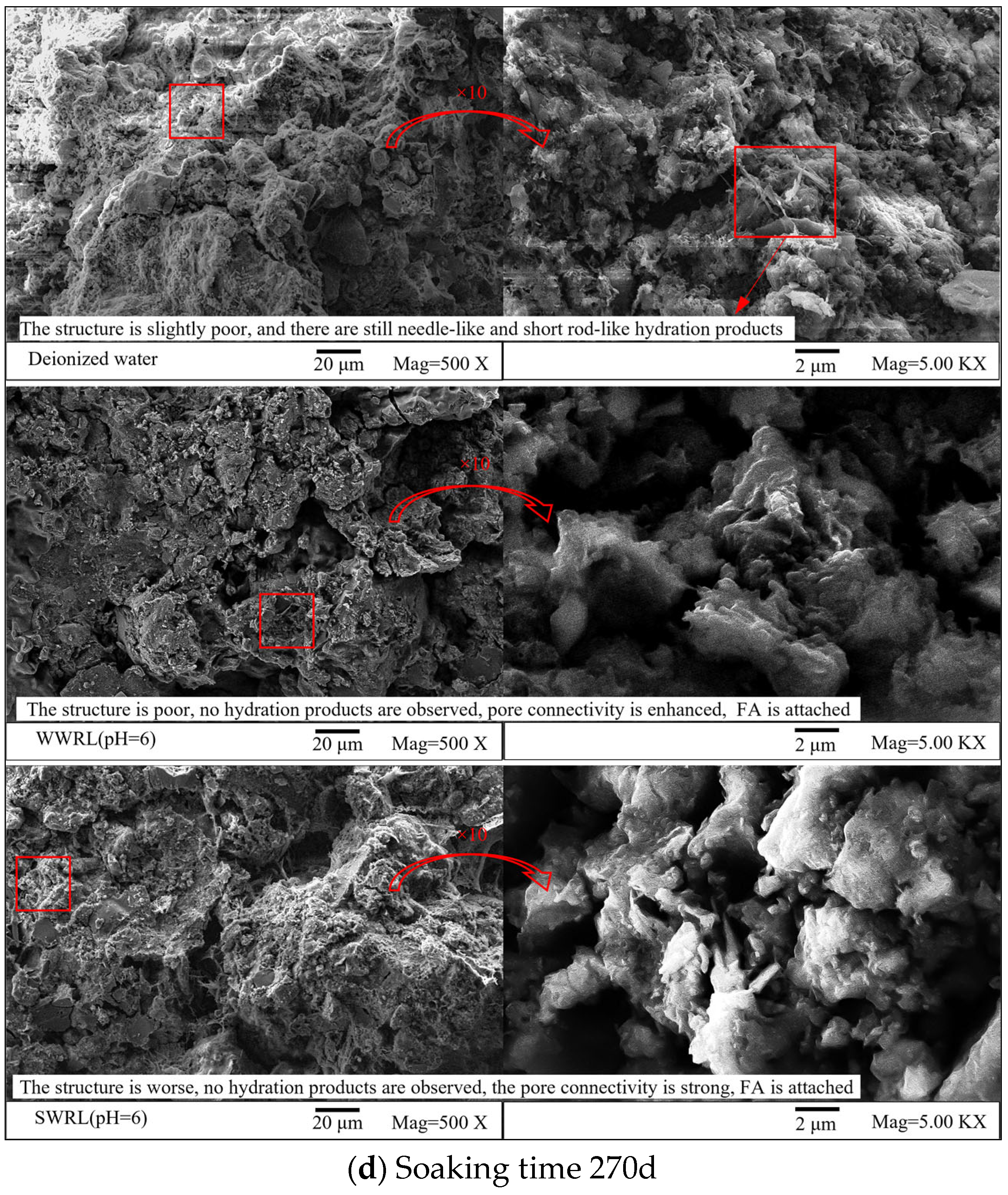
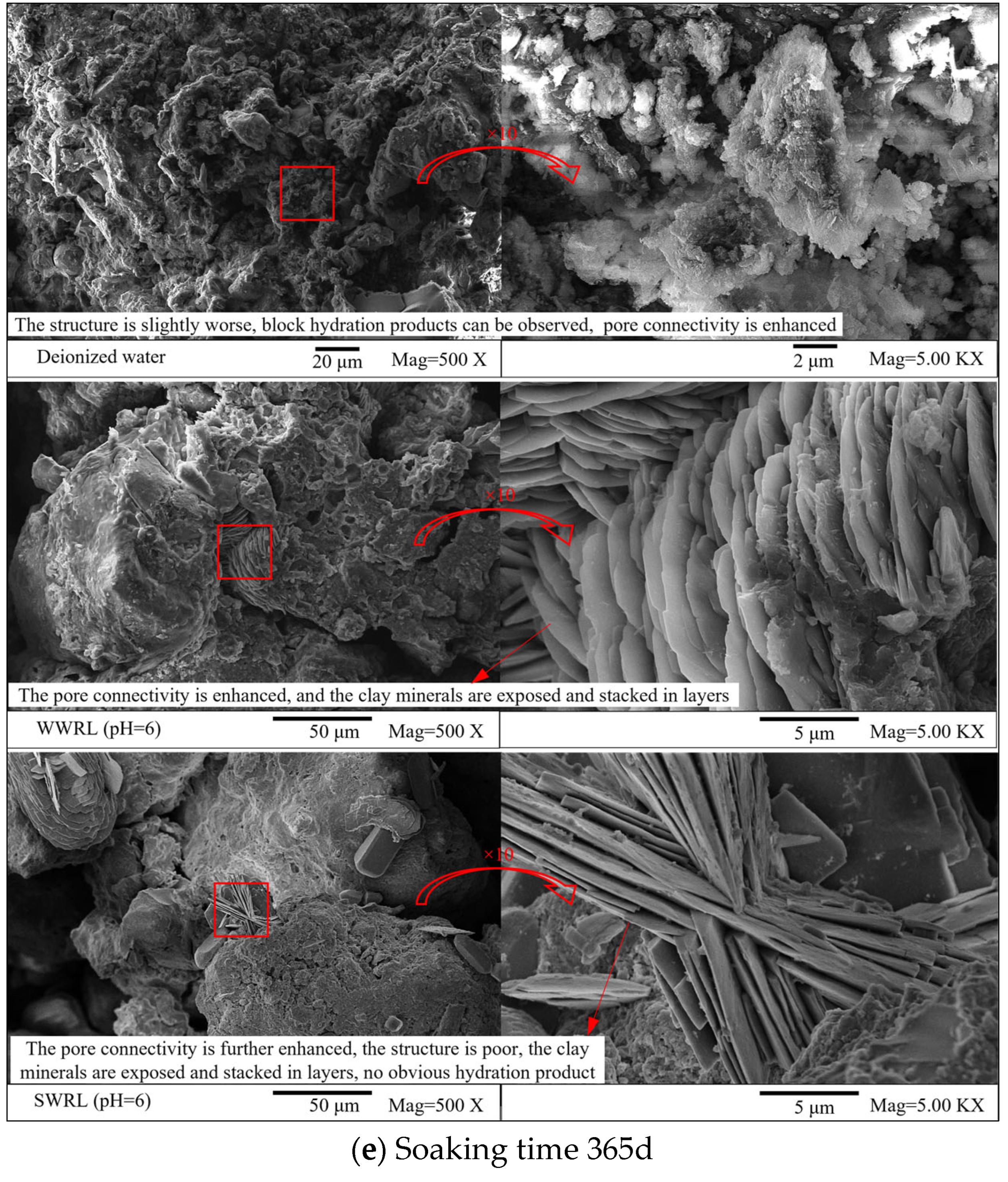
The concentration of HA in the sample subjected to scanning electron microscopy (SEM) testing is 20%, whereas the proportion of HA in the cement mixture is also 20%. The SEM pictures presented in Figure 4a–e depict the samples that were immersed in deionized water and FA solution (pH = 6) for varying durations.
Upon immersion in deionized water, the cement-soil specimens exhibit favorable structural integrity, characterized by relatively diminutive pores, with certain locations occupied by fine fibrous hydrates. As the duration of soaking increases, the hydration products within the pores of cement-soil undergo a gradual transformation, transitioning from a fibrous and flocculent state to a needle-like and short rod-like morphology. This process further strengthens the cement-soil structure, as depicted in Figure 4a–c. When the soaking duration is extended to 270 days and 365 days, the hydration reaction of cement becomes less vigorous and more stable. However, it is observed that some fibrous and flocculent cement hydration products are consumed by HA [23], resulting in the formation of needle-shaped and block-shaped hydration products with a slightly inferior structure, as depicted in Figure 4d,e.
When immersed in an FA solution for 90 days, it can be observed that the distribution of soil particles in the WWRL of the cement-soil mixture is relatively homogeneous. Additionally, a limited quantity of rod-shaped hydration products can be detected. The surface of the cement-soil mixture exhibits adherence with FA, and certain pores within the cement-soil are filled with FA. Conversely, in the SWRL, the presence of acicular and short rod-shaped hydration products can be observed, as depicted in Figure 4a,b. The rationale behind this phenomenon lies in the insufficient duration for complete saturation of the cement-soil mixture and incomplete hydration of cement within the WWRL due to a scarcity of available water. The occurrence of cement hydration is accelerated when the SWRL is saturated with free water. During the period of time ranging from 90 days to 180 days, there is a steady rise in the depth of FA wetting in cement-soil. Additionally, smooth and gummy attachments can be observed within the pores of SWRL and WWRL and on the surface of soil particles, as depicted in Figure 4c. As depicted in Figure 5, the configuration of the attachment closely resembles that of the dissolved FA, indicating that this substance has undergone dissolution in water and subsequent solidification within the pores of the sample. The findings demonstrate that the colloidal characteristics of FA are effectively manifested at present, leading to the filling of some pores in the cement-soil specimens.
Nevertheless, it can be observed from Figure 4d,e that there is a steady decrease in the different kinds of cement hydrates in the SWRL and WWRL as the soaking duration increases from 180 days to 365 days. One possible explanation for this phenomenon is that the presence of PSE leads to the consumption of hydration products, resulting in the exposure of clay particles and further expansion of pores. Consequently, the overall structure of the cement-soil composite gradually deteriorates. Hence, with prolonged utilization of cement-soil in PSE, the structural integrity of the cement-soil undergoes an initial strengthening phase followed by a gradual weakening process.

3.2. MIP Test Results and Analysis

This study applies the MIP (Mercury Intrusion Porosimetry) test to examine pore diameter variability and spatial distribution within cement-soil specimens. The soaking duration was selected as the independent variable and set at 90 days, 270 days, and 365 days. In addition, it also fixed the cement mixing ratio of cement-soil at 20%, the HA content 20%, and FA solution (pH = 6).
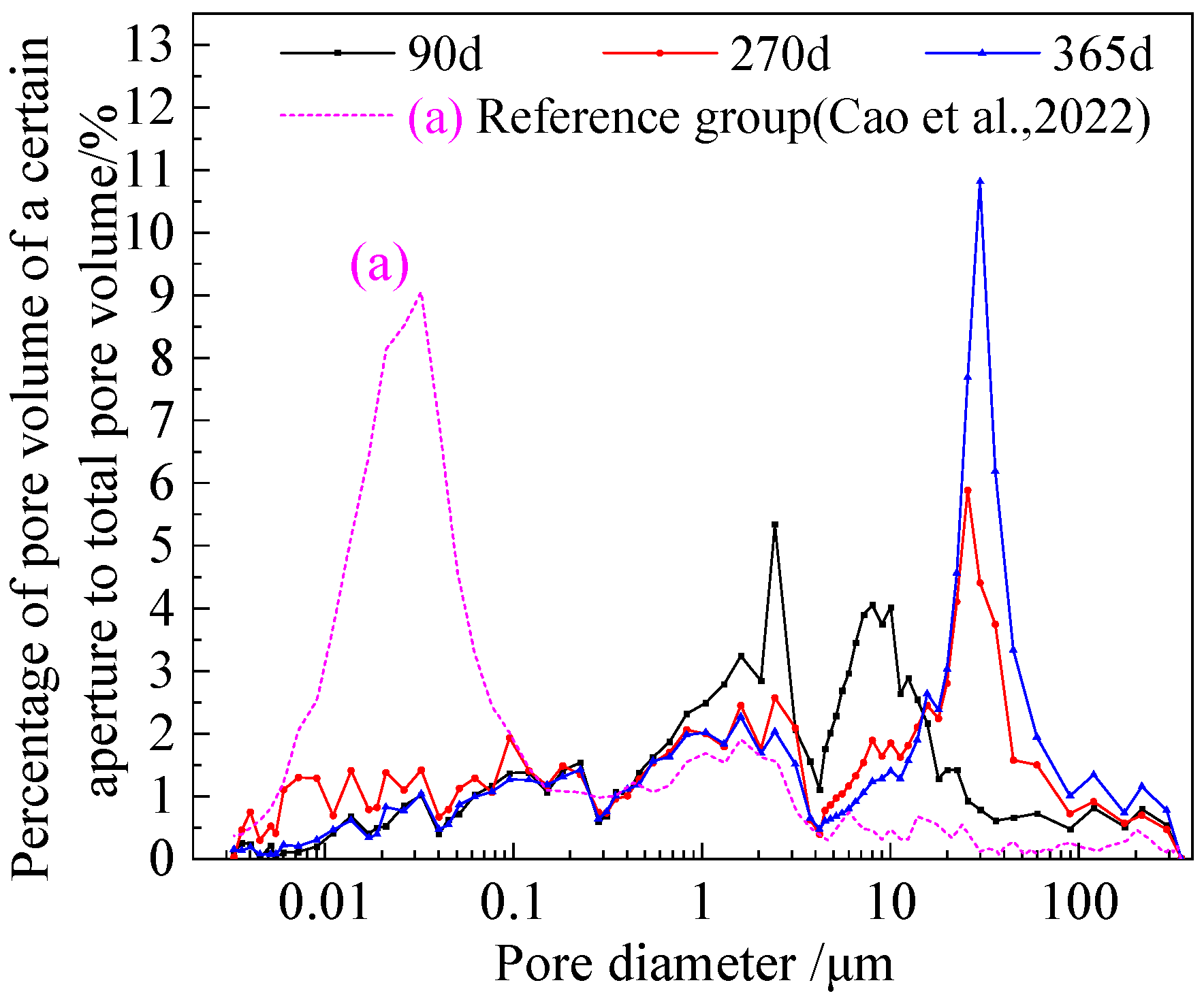
In 2022, Cao et al. [22] used the same test method to conduct MIP tests on cement-soil containing HA. In this test, the soaking solution utilized in this experiment consisted of deionized water; the soaking time of the sample was 90 days, with a cement mixing ratio of 20% and an HA content of 15% (It is worth noting that although there exists a minor disparity in HA content compared with that of this study, the information provided remains very instructive). The results are shown in curve (a) in Figure 6, where the pore diameters of cement-soil containing HA are mainly distributed in the range of 0.01 μm to 0.1 μm. In this test, according to the curve characteristics, the pores were divided into micropores (aperture < 0.01 μm), small pores (aperture 0.01~0.1 μm), medium pores (aperture 0.1~10 μm), and large pores (aperture > 10 μm). Based on the categorization approach utilized by Cao et al., it has been shown that the pores observed in the cement-soil specimens containing HA primarily consist of small pores, ranging in size from 0.01 μm to 0.1 μm. To clarify, the cement-soil specimens analyzed in this experiment predominantly exhibit small pores.
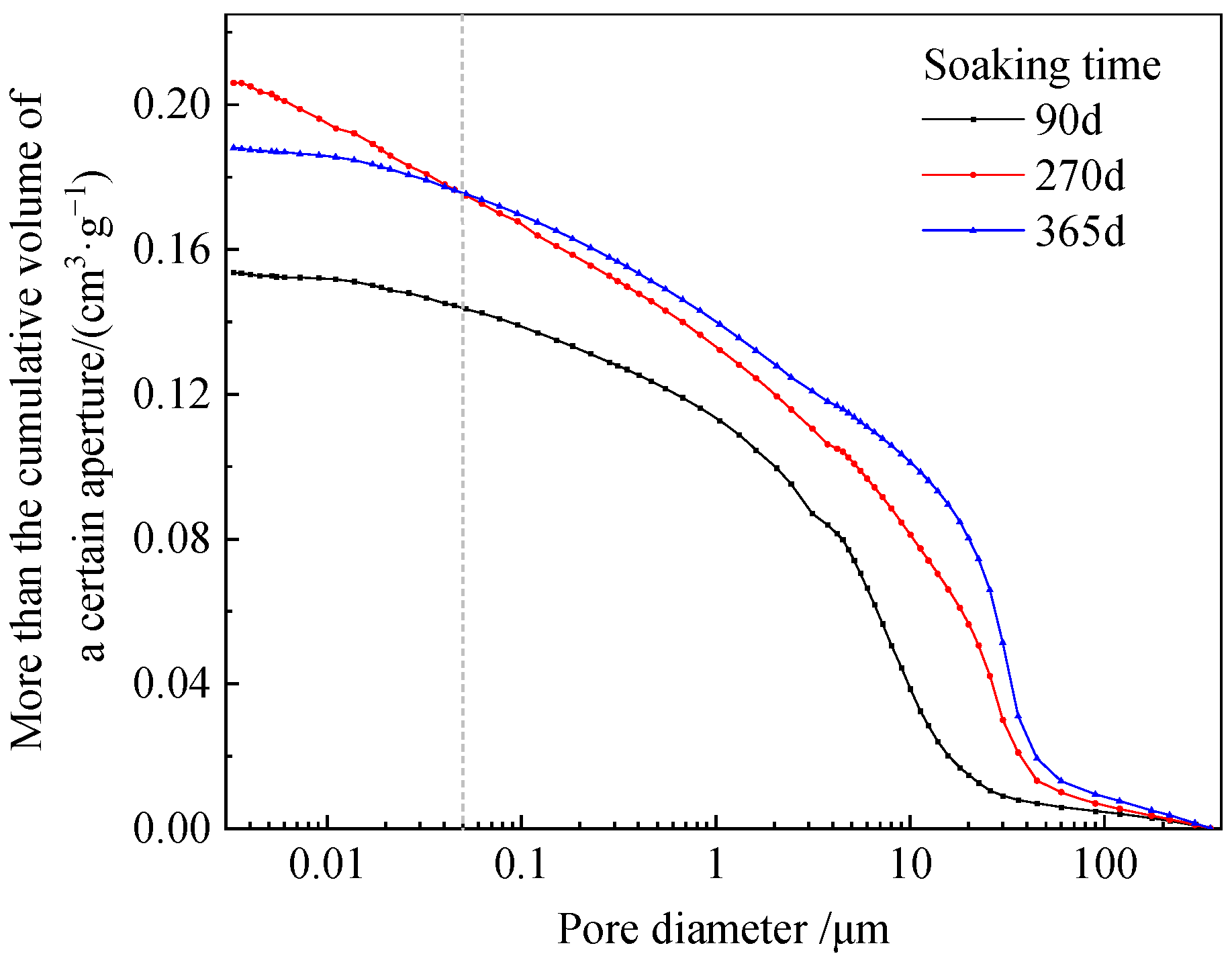
Based on this, the relationship between the percentage of the pore volume of certain pore sizes in cement-soil and the pore size obtained from the MIP test is shown in Figure 6. The relationship curve between cumulative volume greater than a certain pore size and pore size in cement-soil is shown in Figure 7. When the cement-soil is immersed in FA, its pore size is spread within the range of 0.003 μm to 400 μm, with a higher fraction of pore volume falling within the range of 1 μm to 100 μm. Hence, the cement-soil soaked with FA can be classified as a medium-to-large pore medium. The spectrum of pore size distribution in the cement-soil is distinct from that observed in the unsoaked FA solution. The observed phenomenon can be attributed to the fact that upon immersion in FA solution, there is a noticeable rightward shift in the peak of the curve. This shift indicates an increase in pore size within the cement-soil composite, particularly in the medium and large range.
The MIP curves of cement-soil exhibit variations when undergoing three distinct soaking durations. When the soaking duration is 90 days, the pore diameter of the cement-soil mixture is found to be spread across the range of 0.3 μm to 20 μm. The shown curve exhibits two distinct peaks, indicating that the pore size of the cement-soil specimens soaked with FA soaking undergoes significant expansion, resulting in the formation of medium and large pores when compared to curve (a). However, according to Figure 7, the cumulative volume of pore size is still smaller than that of 270 days and 365 days. The pore volume within the range of 0.003 μm to 0.1 μm is found to be greater when the soaking duration is 270 days compared to the other two soaking durations. Furthermore, during the immersion period, a significant fraction of the pore volume in the cement-soil specimens is attributed to pores within the size range of 10 μm to 40 μm. The findings indicate that there is a noticeable corrosion of the cement-soil after being soaked for 270 days, as seen by the comparison of the MIP curves between the 90-day and 270-day samples. The phenomenon of corrosion contributes to the subsequent enlargement of the pore size within the cement-soil specimens, potentially resulting in the transition of closed pores to open pores. Additionally, there is a notable escalation in the volume proportion of micropores and small pores. When the soaking duration is 365 days, the pore volume of the cement-soil mixture with a pore size ranging from 10 μm to 100 μm exhibits an increase in magnitude. The findings indicate that an increase in the soaking period from 90 days to 365 days leads to the cement-soil experiencing a corrosive impact from the PSE. This results in progressive pore size enlargement, with the corrosion effect becoming more evident as the soaking time prolongs. The main reason is that FA contains many acidic functional groups, specifically carboxyl groups [24]. Upon being dissolved in water, a substantial quantity of hydrogen ions undergo ionization and subsequently engage in reactions with the hydration products of cement. The resulting products are soluble salts [25]. Therefore, the amount of hydration products reduced, and some of the hydration products dissolved, which diminished the filling action and increased the pore size.
Figure 7 illustrates the presence of two inflection points in the cumulative volume of cement-soil pores at three distinct soaking time intervals. Furthermore, it has been shown that when the duration of soaking reaches 270 days and 365 days, there is a reversal in the cumulative pore volume of cement-soil at a pore size of around 0.05 μm. The changes mentioned above have been implemented due to the fact that the corrosion of FA leads to the opening of closed micro and small holes, resulting in a significant increase in their volume. The duration of soaking period exhibits an increase from 28 days to 365 days, which has been observed to enhance the unconfined compressive strength (UCS) of cement-soil due to the colloidal properties of FA [9,26,27]. Additionally, it exhibits high acidity and demonstrates evident corrosive properties towards cement-soils during extended periods of exposure, resulting in the dissolution of hydration products and leaching of associated ions. Both factors play a crucial part in the reciprocal alteration of pores in cement-soil, encompassing macropores, medium pores, small pores, and micropores.
Furthermore, the MIP test was conducted to assess the physical properties, specifically permeability and conductivity coefficient, of cement-soil specimens subjected to varying soaking durations. The corresponding findings are presented in Table 4. As the duration of soaking rises, the cement-soil’s permeability significantly increases, accompanied by a progressive increase in its conductivity coefficient (calculated value). The augmentation of pore connectivity is directly proportional to the enhancement of permeability in cement-soil. Consequently, the permeability of conductive liquid within cement-soil experiences a similar elevation, leading to increased conductivity. The initial assessment indicates that the corrosion impact of PSE leads to an improvement in the connection of internal pores in cement-soil. Furthermore, the extent of corrosion becomes more pronounced as the duration of soaking increases.

3.3. PCAS Analysis of Test Results

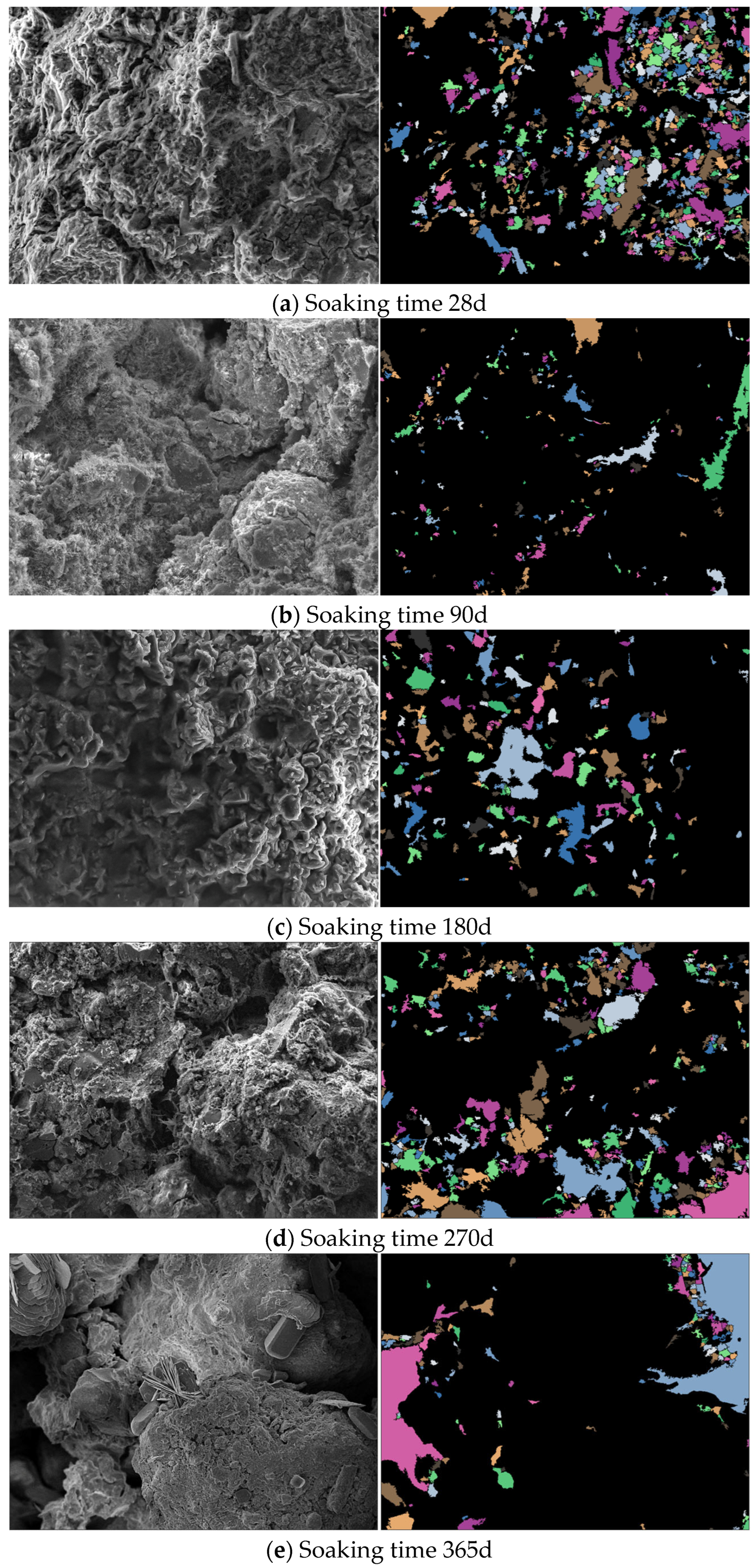
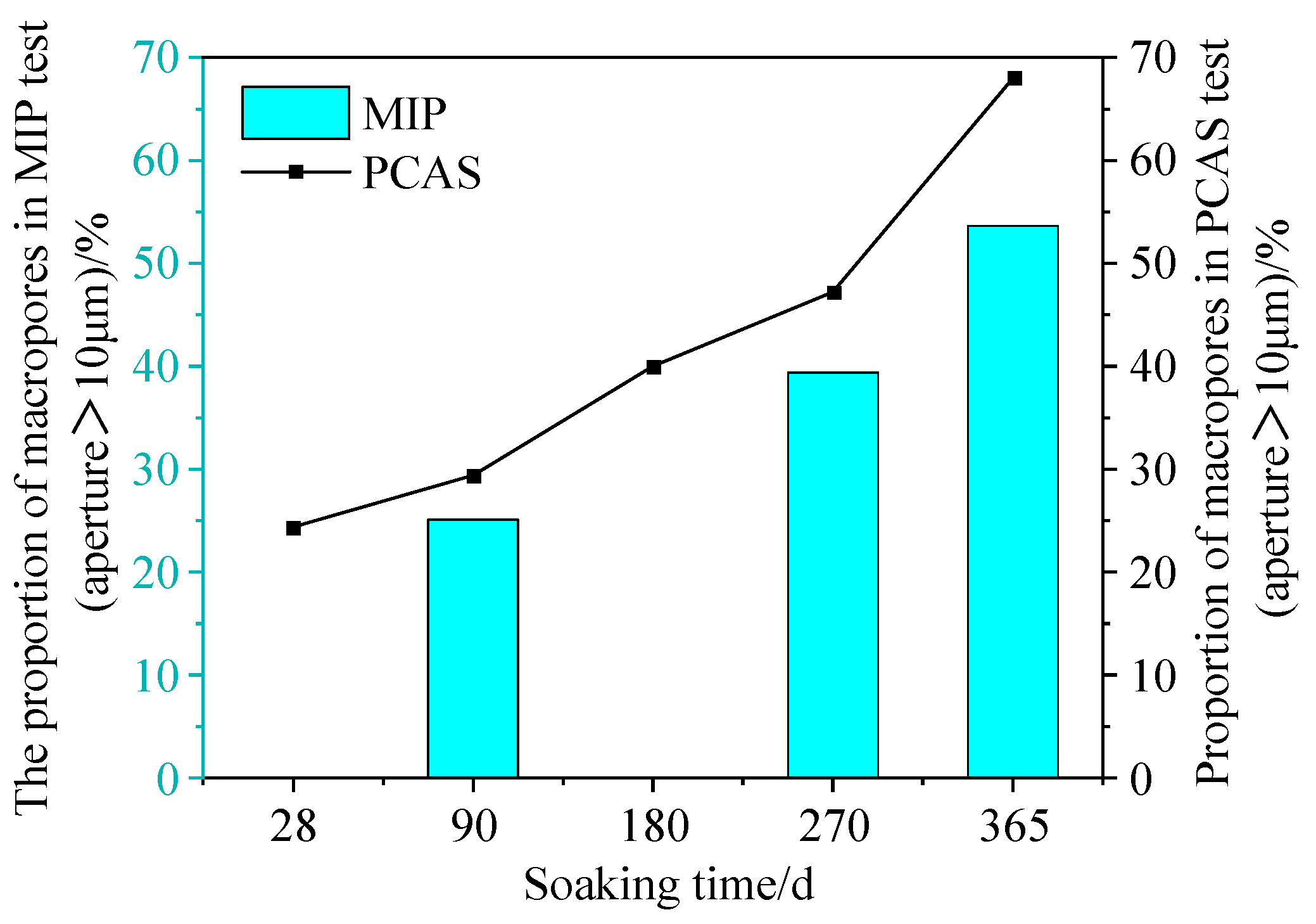
The identification and quantitative (or semi-quantitative) characterization of pore and fracture features in cement-soil are performed using the PCAS test. The PCAS test involves a set of cement-soil specimens with a cement mixing ratio of 20%, an HA content of 20%, and an FA soaking solution with a pH of 6. The soaking period serves as the variable component. The system automatically identifies the pores and cracks in cement-soil composites to study their morphology and geometric parameters. The results of PCAS analysis of pores in cement-soil are shown in Figure 8a–e, and the comparison between PCAS test results and mercury intrusion test results is shown in Figure 9.
When the duration of soaking is 28 days, the cement-soil specimens exhibit a division of the pores on its surface into a multitude of smaller pores, facilitated by the presence of fibrous hydration products, as depicted in Figure 8a. When the soaking duration was extended to 90 days, the pores of the cement-soil mixture were increasingly filled with hydration products. Additionally, at specific locations, the hydration products began to experience corrosion due to the action of FA. The cement-soil specimens has a limited quantity of pores dispersed across its surface. However, it is important to note that these holes are interconnected and possess a thin structure, as depicted in Figure 8b. When the duration of soaking is extended to 180 days, there is a slight improvement in the smoothness of the inner wall of pores on the surface of cement-soil specimens. The initial factor contributing to this phenomena is the dissolution of FA, which subsequently results in an amplified presence of caustic voids in cement-soil, as depicted in Figure 8c. When the soaking duration reaches 270 days, the cement-soil specimens undergo dissolution due to the corrosion caused by fulvic acid. As a result, the connectivity of the pores becomes more pronounced, and the number of macropores in the observed region increases further, as depicted in Figure 8d. When the soaking duration is 365 days, the pores on the surface of the cement-soil specimens undergo erosion caused by FA. As a result, the connection of the holes becomes more evident, leading to their expansion, as depicted in Figure 8e.
The magnitude of the effect on the unconfined compressive strength (UCS) of cement-soil is directly proportional to the size of its pores. PCAS calculated the ratio of the cross-section area of pores with a diameter larger than 10 μm to the total cross-section area of all pores in cement-soil, and the results are shown in Figure 9. As the duration of soaking rises, there is a progressive increase in the proportion of pores in cement-soil with a pore size greater than 10 μm. The rationale behind this phenomenon is that upon immersion of the cement-soil in the FA solution, the FA solution consistently infiltrates the sample and initiates corrosion, leading to a notable augmentation in the macropore fraction. The dissolving effect becomes increasingly evident with prolonged periods of immersion.

3.4. UCS Test Results and Analysis

The relationship curve between the UCS of cement-soil soaked in FA solution (pH = 6) and deionized water and soaking time are shown in Figure 10, with a cement mixing ratio of 20% and an HA content of 20%. The unconfined compressive strength (UCS) of cement-soil in the two soaking solutions exhibited an initial increase followed by a progressive reduction with the prolonged soaking duration. The maximum UCS was observed after 180 days of soaking. When the duration of soaking falls between 28 to 90 days, the UCS of cement-soil specimens soaked in a solution of FA exhibits greater values compared with those soaked in deionized water. In the period spanning from 90 to 180 days, the UCS of cement-soil specimens subjected to immersion in an FA solution exhibits a lower value than those soaked in deionized water. However, it is essential to note that the UCS still shows an upward trend during this period. After being immersed for a duration exceeding 180 days, the UCS of cement-soil specimens soaked in FA solution is lower than those soaked in deionized water. Furthermore, the UCS experiences a rapid drop over time.
The UCS of cement-soil exhibits a strong correlation with its microstructural characteristics. Consequently, a complete analysis is conducted on the results of UCS, SEM, MIP, and PCAS. The findings from the SEM test indicate that certain cement hydration products undergo consumption while the connection of pores is strengthened following the erosion of cement-soil in PSE over 180 days. Hence, the interconnection among the particles underwent a slow transformation, transitioning from surface-to-surface interactions to even point-to-point interactions, resulting in a progressive deterioration of the cement-soil structure. The results of the MIP test indicate a notable increase in the proportion of macropores, permeability, and conductivity coefficient in cement-soil eroded by PSE. The PCAS analysis further supports this finding. Therefore, the peat soil environment’s corrosive impact results in the progressive enlargement of the pores within the cement-soil specimens, heightened connectivity, and even the formation of aerial structures. As a consequence, the strength of the cement-soil mixture exhibits a pattern of gradual increase followed by a rapid decrease as the immersion time progresses.

4. Conclusions

Experiment variables included immersion conditions (deionized water and FA solution) and immersion time (28d, 90d, 180d, 270d, 365d) to explore the corrosion mechanism of FA in the peat soil environment and dynamic process of cement-soil corrosion. The study resulted in the following conclusions:
(1)
The structural characteristics and strength of cement-soil were shown to change over time when exposed to deionized water and peat soil environments. In the presence of deionized water, the structural characteristics of cement-soil exhibited a gradual enhancement followed by a slight weakening. Conversely, when exposed to peat soil, the strength of cement-soil experienced a slow initial increase due to the gelling and filling effects of fulvic acid. However, as time progressed, the corrosive impact of fulvic acid resulted in the deterioration of the cement-soil structure. Consequently, the strength exhibited a pattern of gradual increase followed by a rapid decrease.
(2)
To enhance the durability of cement-solidified soil in peat soil environments, it is essential to adhere to the principles of cost-effectiveness, environmental consciousness, and sustainability. This entails selecting cost-efficient and pragmatic additives that can fortify the structure of cement-soil, decelerate the penetration rate of corrosive substances such as fulvic acid, and enhance its impermeability to withstand corrosion in peat soil environments.

Author Contributions

Conceptualization, J.C. and S.L.; methodology, W.L.; software, Y.S.; validation, J.C., S.L. and Y.S.; formal analysis, S.S.; investigation, H.X.; resources, Y.G.; data curation, W.D.; writing—original draft preparation, S.L.; writing—review and editing, W.L.; visualization, Y.S.; supervision, J.C.; project administration, S.S.; funding acquisition, J.C. All authors have read and agreed to the published version of the manuscript.

Funding

This research was funded by Natural Science Foundation of Yunnan Province (China), grant number 41967035.

Institutional Review Board Statement

Not applicable.

Informed Consent Statement

Not applicable.

Data Availability Statement

The data used to support this study’s findings are included in the article.

Conflicts of Interest

The authors declare no conflict of interest.

References

  1. Gui, Y.; Fu, J.; Wu, C.K.; Cao, J.; Gao, Y.F. Hydraulic conductivity of lacustrine peaty soil in plateau areas and its mechanism analysis. Rock Soil Mech. 2016, 37, 3197–3207. [Google Scholar]
  2. Wang, D.W.; Wang, Q.; Chen, J.P. Research on the distribution regularity and the engineering geological property of peat soil in Dianchi basin. In Proceedings of the 2nd National Geotechnical and Engineering Academic Conference, 28 October–1 November 2006, Wuhan, China; Science Press: Beijing, China, 2006; pp. 831–835. [Google Scholar]
  3. Xue, Y.; Cui, W.X.; Feng, Z.J.; Chen, J.W. The reinfforcement technology of railway’s soft soil foundation in Dian Lake area. J. Railw. Eng. Soc. 2015, 32, 35–40. [Google Scholar]
  4. Tremblay, H.; Duchesne, J.; Locat, J.; Leroueil, S. Influence of the nature of organic compounds on fine soil stabilization with cement. Can. Geotech. J. 2002, 39, 535–546. [Google Scholar] [CrossRef]
  5. Fan, Z.P.; Zhu, W.; Zhang, C.X. Experimental study on influence of organic matter content on solidified dredging. Rock Soil Mech. 2005, 26, 1327–1330+1334. [Google Scholar]
  6. Feng, C.; Wang, B.T.; Li, S.D. Experimental study on solidified organic sludge. Geotech. Eng. Tech. 2010, 24, 142–146. [Google Scholar]
  7. Xun, Y. The anti-influences and influences of containing organic matter on cement soil strength. Build. Sci. Res. Sichuan 2000, 3, 58–59. [Google Scholar]
  8. Cao, J.; Song, Y.F.; Gao, Y. Preliminary experimental study on the corrosiveness of humic group to cement-soil. J. Saf. Environ. 2022, 1–10. [Google Scholar] [CrossRef]
  9. Gong, G.Q.; Xu, L.W.; Zhang, Y.J.; Liu, W.X.; Wang, M.; Zhao, Y.F.; Yuan, X.; Li, Y.J. Extraction of fulvic acid from lignite and characterization of its functional groups. ACS Omega 2020, 5, 27953–27961. [Google Scholar] [CrossRef]
  10. El Howayek, A.; Bobet, A.; Santagata, M. Microstructure and cementation of two carbonatic fine-grained soils. Can. Geotech. J. 2019, 56, 320–334. [Google Scholar] [CrossRef]
  11. Yao, K.; Wang, W.; Li, N.; Zhang, C.; Wang, L.X. Investigation on strength and microstructure characteristics of nano-MgO admixed with cemented soft soil. Constr. Build. Mater. 2019, 206, 160–168. [Google Scholar] [CrossRef]
  12. Ruan, B.; Ding, H.; Teng, J.D.; Deng, W.; Zheng, S.L.; Ruan, C.X. Mechanical properties and microstructure of polypropylene fiber reinforced cement mortar soil. KSCE J. Civ. Eng. 2021, 25, 1985–1997. [Google Scholar] [CrossRef]
  13. Jiang, N.; Wang, C.M.; Wang, Z.P.; Li, B.L.; Liu, Y.A. Strength characteristics and microstructure of cement stabilized soft soil admixed with silica fume. Materials 2021, 14, 1929. [Google Scholar] [CrossRef]
  14. Chen, Z.; Xu, H.C.; Cheng, M.Y.; Lu, H.W.; Wang, Z.J.; Feng, P.Y. Dynamic triaxial test and microscopic study of solidified muddy soil with different mixing ratios and curing ages. Front. Mater. 2021, 8, 731449. [Google Scholar] [CrossRef]
  15. Chen, Q.S.; Yu, R.H.; Tao, G.; Nimbalkar, S. Microstructure, strength and durability of nano-cemented soils under different seawater conditions: Laboratory study. Acta Geotech. 2022, 18, 1607–1627. [Google Scholar] [CrossRef]
  16. Hu, X.P.; Zhao, Z.H. Study on water retention property of cemented dredged material based on MIP. Yellow River 2016, 38, 116–119. [Google Scholar]
  17. Qu, Z.K.; Wang, H.J.; Xun, W.F.; Liu, G.S.; Bian, H.B. Study on permeability characteristics of modified soil based on mercuey intrusion. South-North Water Transf. Water Sci. Technol. 2017, 15, 172–178. [Google Scholar]
  18. Bozbey, İ. Microfabric evaluation of lime-treated clays by mercury intrusion porosimetry and environment scanning electron microscopy. Int. J. Civ. Eng. 2018, 16, 443–456. [Google Scholar] [CrossRef]
  19. Chen, X.; Liu, X.; Dong, S.H.; Ge, Y. Cement hydration and pore structure development in low arioressure and low humidity. J. Xi’an Univ. Archit. Technol. 2021, 53, 202–207. [Google Scholar]
  20. Song, Y.F.; Cao, J.; Ding, W.Y.; Song, Z.G.; Liu, H.; Huang, S.Y.; Zhu, W.M. Influence of peat soil environment on mechanical properties of cement-soil and its mechanism. Sustainability 2023, 15, 4580. [Google Scholar] [CrossRef]
  21. Cao, J.; Huang, S.Y.; Liu, W.L.; Kong, C.; Gao, Y.; Liu, F.Y. Study on simulation test of peat soil environment in Dianchi Lake. Adv. Civ. Eng. 2022, 2022, 1437733. [Google Scholar] [CrossRef]
  22. GB/T 50123-2019; Ministry of Water Resources of the People’s Republic of China. Standard for Geotechnical Testing Method. China Planning Press: Beijing, China, 2019.
  23. Cao, J.; Huang, S.Y.; Liu, W.L.; Gao, Y.; Song, Y.F.; Li, S.P. Study on strength development and microstructure of cement-solidified peat soil containing humic acid of Dianchi Lake. Adv. Mater. Sci. Eng. 2022, 2022, 8136852. [Google Scholar] [CrossRef]
  24. Stevenson, F.J. Humus Chemistry: Genesis, Composition, Reactions; John Wiley & Sons: New York, NY, USA, 1994. [Google Scholar]
  25. Shao, Y.F. Study on Humus-Containing Soil Stabilization; Zhejiang University: Hangzhou, China, 2006. [Google Scholar]
  26. Jones, M.N.; Bryan, N.D. Colloidal properties of humic substances. Adv. Colloid Interface Sci. 1998, 78, 1–48. [Google Scholar] [CrossRef]
  27. Lee, C.L.; Kuo, L.J.; Wang, H.L.; Hsieh, P.C. Effects of ionic strength on the binding of phenanthrene and pyrene to humic substances: Three-stage variation model. Water Res. 2003, 37, 4250–4258. [Google Scholar] [CrossRef] [PubMed]
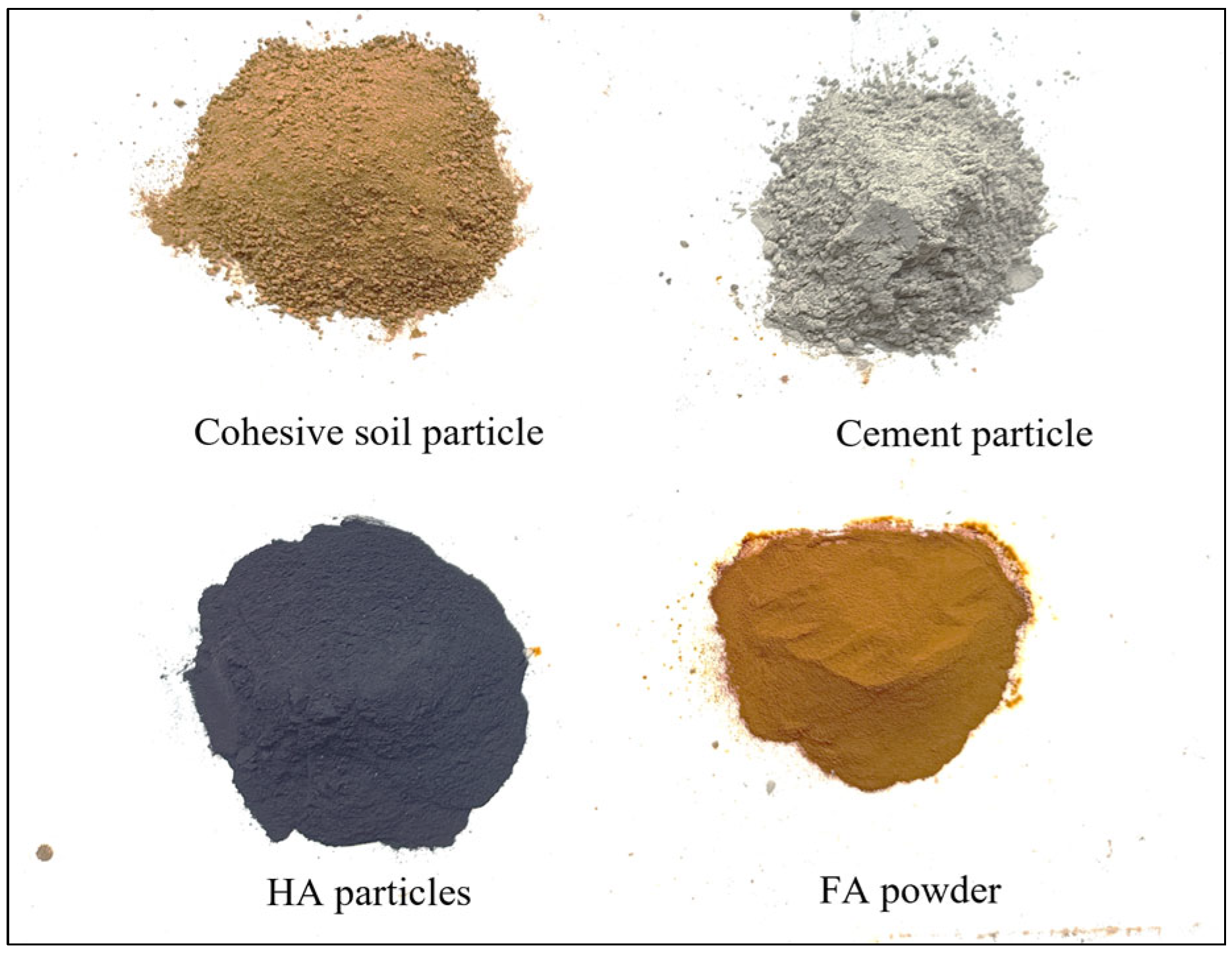
Figure 1. The materials used in the test.
Coatings 13 01366 g001
Figure 2. XRD diffraction pattern of alluvial cohesive soil.
Coatings 13 01366 g002
Figure 3. Sample preparation process.
Coatings 13 01366 g003
Figure 4. SEM diagram of SWRL and WWRL at each soaking time (500–5000 times magnification).
Coatings 13 01366 g004aCoatings 13 01366 g004bCoatings 13 01366 g004cCoatings 13 01366 g004dCoatings 13 01366 g004e
Figure 5. SEM images of FA (500, 2000, 5000 times).
Coatings 13 01366 g005
Figure 6. The relationship between the percentage of the pore volume of certain pore sizes in cement-soil and the pore size (λ = 20%, β = 20%, pH = 6). (a) Reference group (Cao et al., 2022) [21].
Coatings 13 01366 g006
Figure 7. Relationship curve between cumulative volume greater than a certain pore size and pore size in cement-soil (λ = 20%, β = 20%, pH = 6).
Coatings 13 01366 g007
Figure 8. Analysis results of pores in cement-soil by PCAS (λ = 20%, β = 20%, pH = 6).
Coatings 13 01366 g008
Figure 9. Comparison of PCAS test results and MIP test results.
Coatings 13 01366 g009
Figure 10. Relationship curve between UCS and soaking time of cement-soil specimens (β = 20%, λ = 20%).
Coatings 13 01366 g010
Table 1. Indicators of fundamental physical properties of the soil used in the test.
Test SoilNatural Water
Content (%)
Liquid Limit WL (%)Plastic Limit WP (%)Natural Density (g·cm−3)Grain Specific
Gravity Gs
Cohesive soil18.6039.2023.001.962.84
Table 2. Chemical composition of the soil used for the test and mass fraction of each composition.
Test SoilThe Chemical Composition and Its Mass Fraction (%)
SiO2Fe2O3Al2O3TiO2K2OMgOCaONa2OMnOP2O5LOI
Cohesive soil46.5721.2220.808.900.480.480.160.040.140.570.64
Table 3. Test scheme.
Testing ItemCement Mixing Ratio (β)/%HA Content (λ)/%Soaking Time/dSoaking Solution
SEM202028, 90, 180, 270, 365FA solution (pH = 6), Deionized water
MIP90, 270, 365FA solution (pH = 6)
PCAS28, 90, 180, 270, 365FA solution (pH = 6)
UCS28, 90, 180, 270, 365FA solution (pH = 6), Deionized water
Table 4. Permeability and conductivity coefficient of cement-soil under MIP (λ = 20%, β = 20%, pH = 6).
Physical Properties of Cement-Soil Measured by MIPSoaking Time/d
90270365
Permeability/md39.0371308.4046597.4950
Conductivity coefficient (calculated value)0.08200.09600.1310
Disclaimer/Publisher’s Note: The statements, opinions and data contained in all publications are solely those of the individual author(s) and contributor(s) and not of MDPI and/or the editor(s). MDPI and/or the editor(s) disclaim responsibility for any injury to people or property resulting from any ideas, methods, instructions or products referred to in the content.