Article

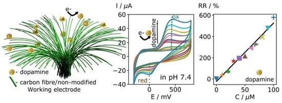
Examination of Non-Modified Carbon Fibre Bundle as an Electrode for Electrochemical Sensing

1
Institute of Technology, University of Tartu, Nooruse 1, 50411 Tartu, Estonia
2
Wellcome/Cancer Research UK Gurdon Institute, University of Cambridge, Cambridge CB2 1QN, UK
3
Faculty of Chemical Technology, Kaunas University of Technology, 50254 Kaunas, Lithuania
4
State Research Institute Center for Physical Sciences and Technology, 02300 Vilnius, Lithuania
*
Author to whom correspondence should be addressed.
Coatings 2023, 13(8), 1372; https://doi.org/10.3390/coatings13081372
Submission received: 10 July 2023 / Revised: 27 July 2023 / Accepted: 2 August 2023 / Published: 4 August 2023

Abstract

:
This study presents a simple and cost-effective method for producing carbon fibre microcylinder bundle (CFMB) electrodes that are highly stable and reproducible for electrochemical sensing applications. The CFMBs were integrated into a 3D-printed electrochemical cell and tested for dopamine (DA) detection. The results demonstrated a linear increase in current with increasing DA concentration, reaching a sensitivity of 428 nAμM−1 and a limit of detection (LOD) of 8.85 μM. The CFMBs also showed high electrochemical selectivity for DA due to the similar oxidation potentials of dopamine and the chemical groups present on the surface of the CFMBs. The reproducibility of the CFMBs was also demonstrated by the low variation in background currents between different electrodes. These findings highlight the potential of CFMBs as a low-cost and effective platform for electrochemical sensing applications.

Graphical Abstract

1. Introduction

Recently, carbon-based materials have become the most commonly used electrode materials in electrochemical applications due to their excellent electrical conductivity, low cost, and ease of modification [1,2,3,4,5,6].
Among carbon-based materials, carbon fibres have been highlighted for their mechanical properties, high flexibility, and conductivity, as well as their high oxygen and hydrogen assessment overpotential and corrosion resistance [7,8,9,10,11,12,13].
However, from an electroanalysis point of view, the performance of electrodes made of carbon fibre microcylinder bundles (CFMBs) has been comparatively lower than that of other solid carbon electrodes, such as glassy carbon electrodes (GCEs) or screen-printed carbon electrodes (SPCEs). Although the CFMB material is available at low cost, as roving from several suppliers and application of it for biosensing would have a huge impact on research, studies of its use as an electrode material have been limited to a few analytes (e.g., FAD, NADH, ascorbic acid, p-aminophenol, glutathione) [14,15,16] or neural recordings [17].
Furthermore, CFMB electrodes are typically protected with a polymer coating layer (epoxy, polyester, urethane) for fibre shielding and alignment [18], and it has been suggested that this coating may interfere with the electrochemical signal [15].
To overcome this issue, CFMB electrodes are usually pre-treated using oxidative treatments, such as chemical, thermal, laser, electrochemical, or plasma treatments, prior to electrochemical sensing [15,19,20,21,22,23]. However, these modifications include coating the fibre surface with polymers, such as polymethylmethacrylate [24], poly(9-tosyl-9H-carbazole-co-pyrrole) [25] or poly[N-vinylcarbazole-co-vinyl benzene sulfonic acid] [14,26,27] and nafion [28], or pyrrole, phenylpyrrole, and methoxyphenyl pyrrole [29]. Unfortunately, these coating methods can cause a heterogeneous distribution of nanomaterials on the electrode surface, leading to low reproducibility or a reduction in long-term stability [30].
One of the possible solutions is to use non-modified CFMB, which refers to electrodes without additional treatment or modification. However, the electrochemical characterisation of non-modified CFMB in the literature is poorly reported and requires additional examination.
Therefore, the objective of this study was to investigate the performance of non-modified carbon fibre microcylinder bundle (CFMB) electrodes for the electrochemical detection of dopamine (DA) in a 3D-printed electrochemical cell. The novelty of this study lies in the demonstration of the feasibility of using non-modified CFMB electrodes for sensitive and selective DA detection without the need for electrode modification or pre-treatment.
DA was chosen as a type of neurotransmitter, which plays a critical role in cardiac and nervous system activity and in body weight regulation, and is a biomarker for disorders such as Parkinson’s disease [31] as well as in various types of addiction [32].
Moreover, the detection of DA and its precursors, such as phenylalanine and tyrosine, is of immense importance in both clinical and research settings [23,33,34]. These precursors are integral to the biosynthesis of DA, and their detection can provide valuable insights into the functioning of the dopaminergic system and related disorders [35]. Phenylalanine and tyrosine are converted into DA through a series of enzymatic reactions, and changes in their levels can reflect alterations in DA synthesis and metabolism [36]. Therefore, the simultaneous detection of DA and its precursors can provide a more comprehensive understanding of dopaminergic neurotransmission and its dysregulation in various neurological disorders.
The main objective of this manuscript was to investigate the performance of non-modified carbon fibre microcylinder bundle (CFMB) electrodes for the electrochemical detection of dopamine (DA) in a 3D-printed electrochemical cell. The novelty of this study lies in the demonstration of the feasibility of using non-modified CFMB electrodes for sensitive and selective DA detection without the need for electrode modification or pre-treatment. This study also investigates the reproducibility and stability of CFMB electrodes as well as their potential for electrochemical selectivity towards other analytes. In this work, electrochemical methods were used to characterise untreated carbon fibre bundle electrodes composed of hundreds of 7 µm diameter single-fibre units. The heterogeneous electron transfer rate constant, an indication of the speed of electron transfer between an electroactive species and an electrode surface, was analysed and compared to various carbon electrodes described in the literature. Also, an untreated, non-modified carbon electrode was demonstrated to be applicable for dopamine sensing in a neutral pH phosphate buffer.
Our results showed that these electrodes were able to detect dopamine with good sensitivity and accuracy and were stable over long-term use. These findings suggest that non-modified carbon fibre bundles could be a valuable alternative to traditional electrodes for electrochemical sensing of dopamine and, potentially, other analytes.

2. Experimental

2.1. Materials

All reagents were of analytical grade and used as received without any further purification. For the fabrication of the CFMB electrodes, carbon fibre (SIGRAFIL®C30, EPY 382-000A/50k/3300 with 1% epoxy sizing agent, (SGL Carbon, Meitingen, Germany) was used. All solutions were prepared in MilliQ water (18.2 MΩ·cm). Phosphate buffer (PB) was made by mixing 0.2 M NaHPO4 monobasic (Sigma Aldrich, Burlington, MA, USA) and 0.2 M Na2HPO4 dibasic (Sigma Aldrich, Burlington, MA, USA) aqueous solutions to obtain a pH of 7.4 and diluted up to 0.1 M of total concentration. The 2.5 mM [Fe(CN)6]3−/4− was made by mixing fresh Na4Fe(CN)6·10H2O (Sigma Aldrich, Burlington, MA, USA) and K3Fe(CN)6 (Sigma Aldrich, Burlington, MA, USA). For 3D printing, an electrochemical cap flexible Ninjaflex (NinjaTex, Lititz, PA, USA) filament was used. For the DA investigation, the dopamine hydrochloride (>99%) (Alfa Aesar, Ward Hill, MA, USA) was freshly prepared in PB before the electrochemical measurements to prevent a self-oxidation reaction of DA. The DA concentrations analysed were 10, 20, 30, 40, 50, 60, 70, 80, 90, and 100 µM.

2.2. Instrumentation

The morphology of the CFMB electrode was analysed using a scanning electron microscope (SEM) equipped with an EDX detector (Hitachi High-Technologies Corp, Tokyo, Japan) at an accelerating voltage of 15 kV. Before the SEM measurements, the CFMB was exposed to liquid nitrogen and sliced using tweezers for cross-section imaging. The SEM images were analysed using the open-source software ImageJ Fiji (version 2.0.0.-RC-65/1.53c). The electrochemical cell design was provided by Deep Scientific (Vilnius, Lithuania). For 3D printing, the Prusa i3 MK3s (Prusa Research, Prague, Check Republic) printer was used with support from the software PrusaSlicer (version 2.5.0). Electrochemical measurements were obtained with an electrochemistry workstation Biologic BP-300 (Bio-Logic, Seyssinet-Pariset, France) using a platinum grid as a counter and Ag/AgCl/(3 M KCl) as a reference electrode.

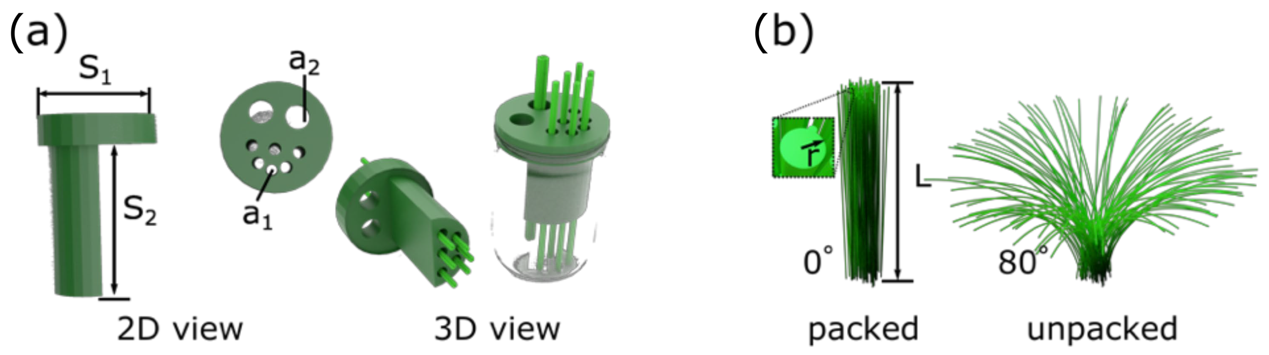
2.3. Optimisation of 3D-Printed Electrochemical Cell and Electrode Design

The electrochemical cell was assembled using a 3D-printed cap (Figure 1) designed (using SolidWorks 2021 SP2.0) to be suitable for the multiplexing of 6 units of CFMB electrodes. The electrochemical cell has a diameter (S1) of 26 mm and consists of 6 channels with a diameter (a1) of 3 mm and a length (S2) of 44 mm. These dimensions were chosen to prevent interaction between the flexible CFMB electrodes. Additionally, 2 units of cavities were designed with a diameter (a2) of 6 mm for the reference and counter electrodes (Figure 1a).
For 3D printing, a nozzle of 0.4 mm flexible filament was used as the material, as it is elastic and resistant to deformation [37]. The filament was printed with an extrusion temperature of 240 °C and a bed temperature of 50 °C. The printing speed was optimised to 20 mms−1 with a 0.2 mm slice taking a total printing time of 1 h 57 min. Prior to use, the glassware was washed twice for 7 min using the SC1 procedure described in previous work [38,39]. The CFMB electrodes were placed into a 3D-printed cap to resolve the resilience of the fibre microunits and to increase the reproducibility of the length and electrochemical response.
For fabrication of the CFMB electrode, a 900-fibre unit bunch with a chopped length of 12 cm was used. The capillary was sealed with a single drop of nitrocellulose to form a hydrophobic barrier. The electrical connection was formed at the far end of the capillary.
The CFMB electrodes were inserted into the 3D-printed cap and dipped into the solution to keep the electrode area constant with a fixed length (L) of 2 × 10⁻² m (Figure 1b). In Figure 1b, two considerations of the electrode area are shown (discussed below). For the electrochemical analysis, the electrodes were used without any treatment, activation, or modification.

3. Results and Discussion

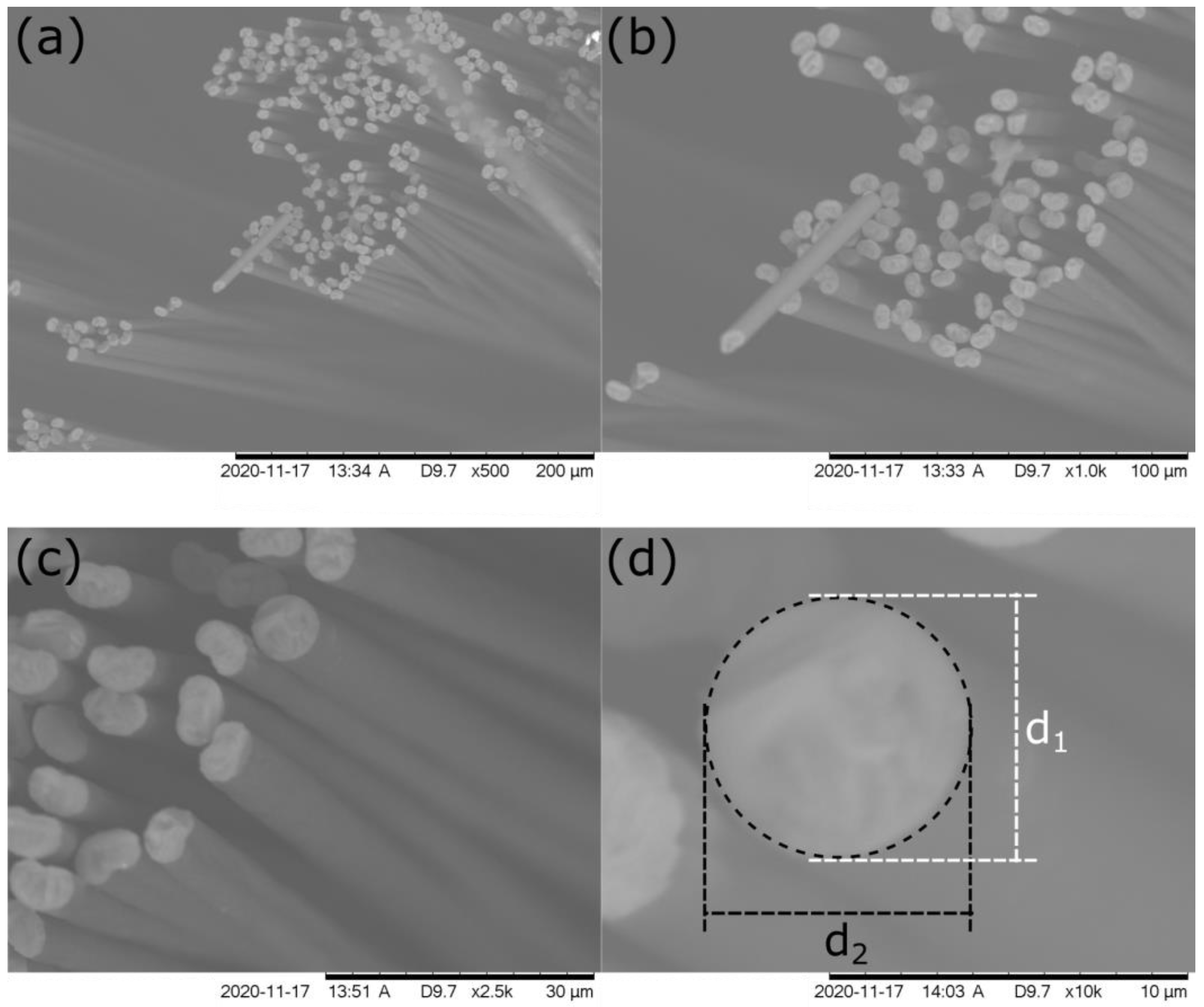
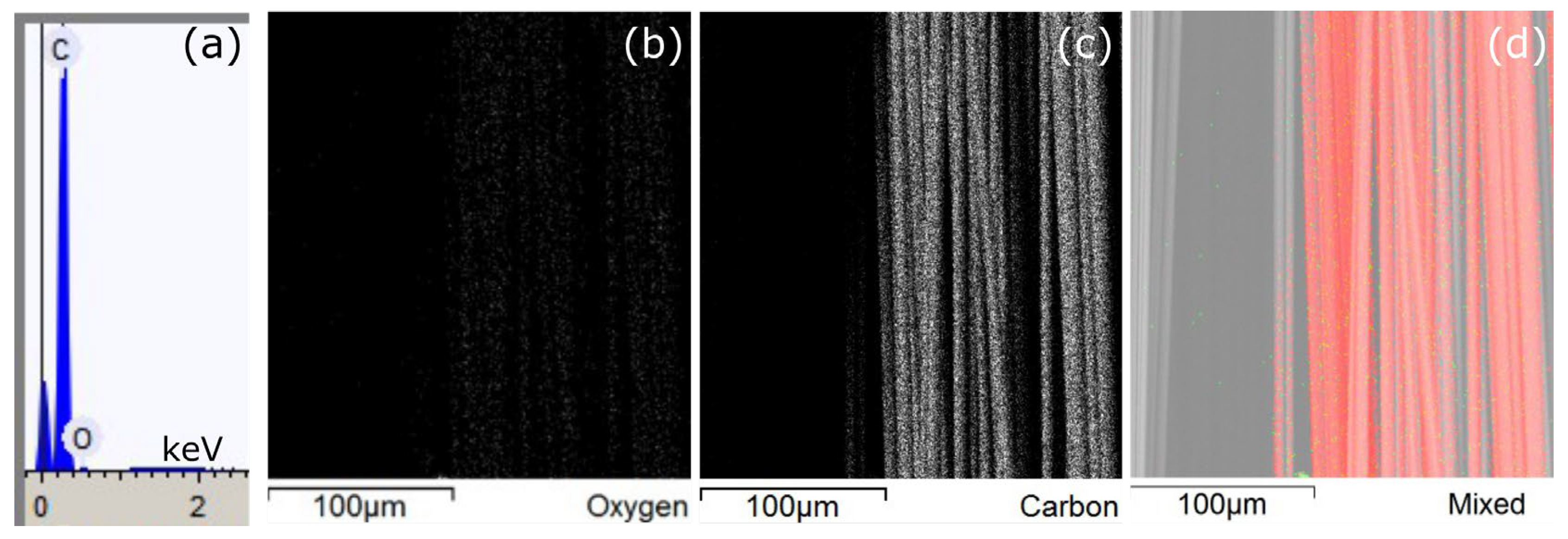
3.1. Characterisation of the CFMB Electrode Geometrical Area

The SEM analysis of the CFMB electrode after cutting it to the length of 12 cm using liquid nitrogen is shown at different magnifications in Figure 2a–d. The diameter (d) for a single fibre unit was calculated to be d = (d1 + d2)/2, where d1 is the diameter of the unit in the y-axis, and d2 is the diameter of the unit in the x-axis cross-section (shown in Figure 2d). The calculated d value of 6.05 ± 0.66 µm (obtained from 160 measurements of the carbon fibre microcylinder units) is close to the values reported previously (6.62 ± 0.34 µm) [18].
The number (N) of microcylinder units was found to be 843 and was calculated using the mass of CFMB (as N = m/πr2 × ρ × L0), where m is the mass of CFMB (7 × 10⁻³ g), r is the radius of a single fibre microcylinder unit (calculated from SEM, Figure 2d), ρ is the density of CFMB (1.8 × 10⁶ gm−3), and L0 is the total length of the CFMB electrode (12 cm).
Two different cases of the geometrical area of CFMB were considered (Figure 1b). In the case of wet CFMB in the air (packed, Figure 1b), the fibre units are packed tightly together, and only the external area (Apacked) of the electrode (considering the whole CFMB as a single cylinder) was used for the area calculation. In the case of wet CFMB in the water (unpacked, Figure 1b), the fibre units are unpacked, and the external area of each single cylinder of the electrode (Aunpacked) was used for the area calculation.
The area (Apacked) was calculated as Apacked = π(w/2)2 (1 + L) with the value of Apacked = 0.32 ± 0.1 cm2, where w is the width of the electrode (w = 5.8 ± 0.2 mm), and L is the length of the electrode (L = 120 ± 0.4 mm), giving the value of 3.9 cm2.
In the case of fibre units in water, the CFMB are in an unpacked state, and the area was calculated as Aunpacked = πr2 × N(1 + L), where r is the radius of a single unit of fibre (calculated from SEM, where d = 6.05 ± 0.66 µm), giving the value of 3.9 cm2. In calculating the geometrical surface area (A) of the CFMB electrode in water (Figure 1b), each underwater cylindrical microunit was considered to have an independent area, and so the following equation was used: A = 2 mL/ρrL0, where L0 is the total length of the CFMB electrode, and L is the length of the CFMB electrode immersed in the electrolyte. The calculated geometrical surface area of the CFMB was 3.9 ± 0.1 cm2, and this value was used further for the normalisation of the electrochemical signals and the calculations of the diffusion coefficients.

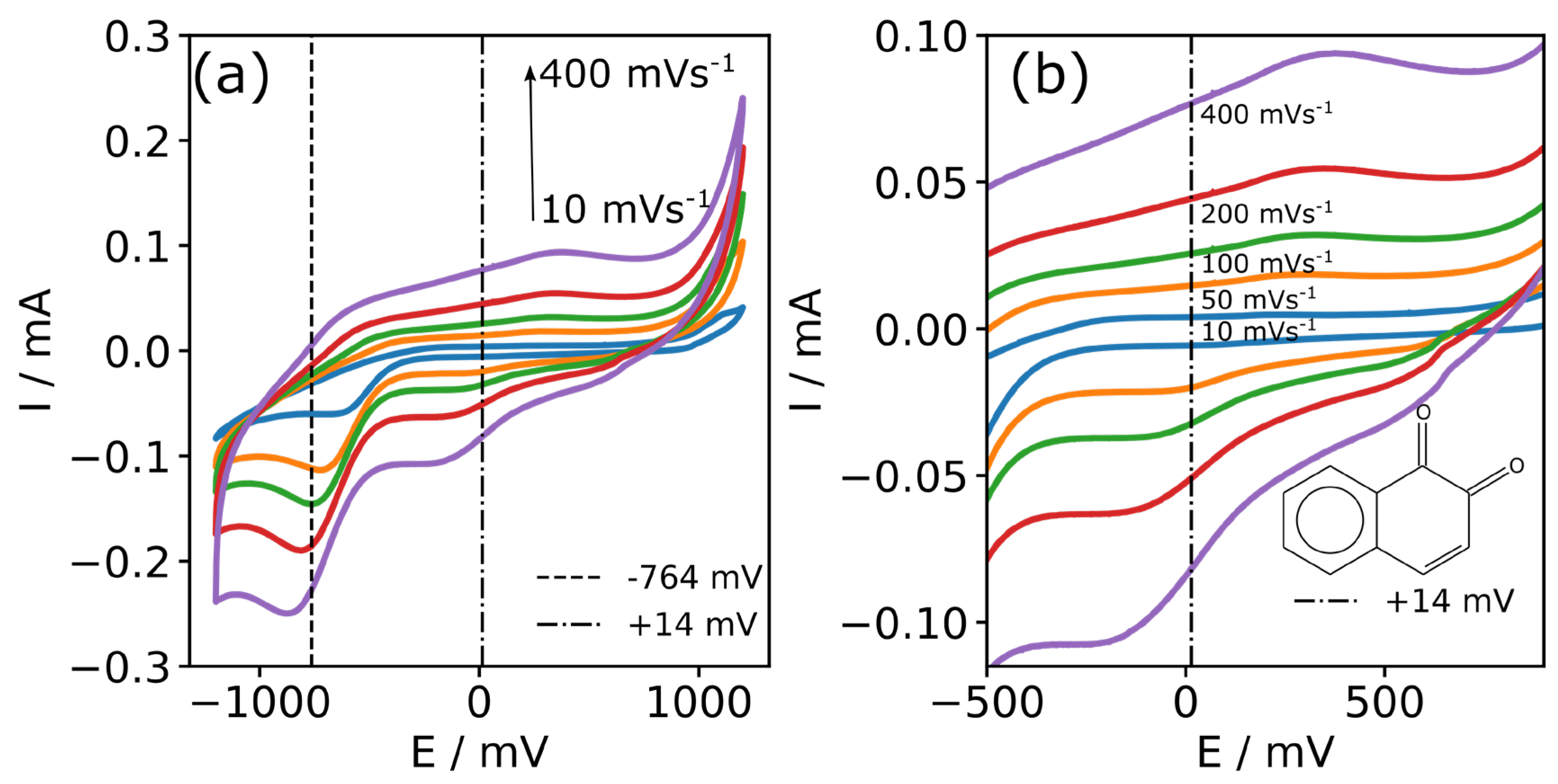
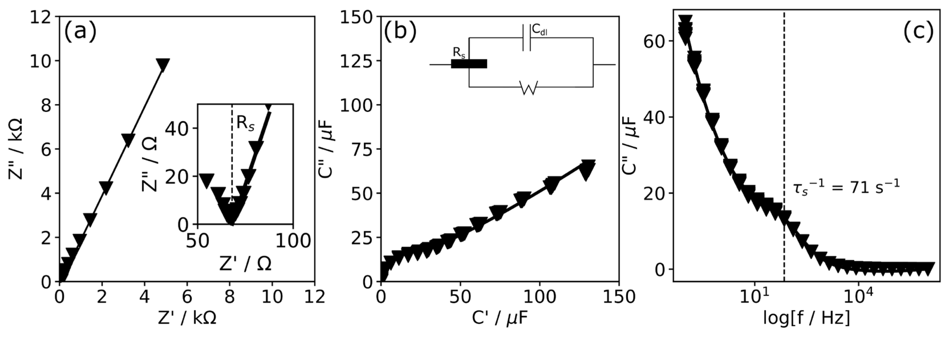
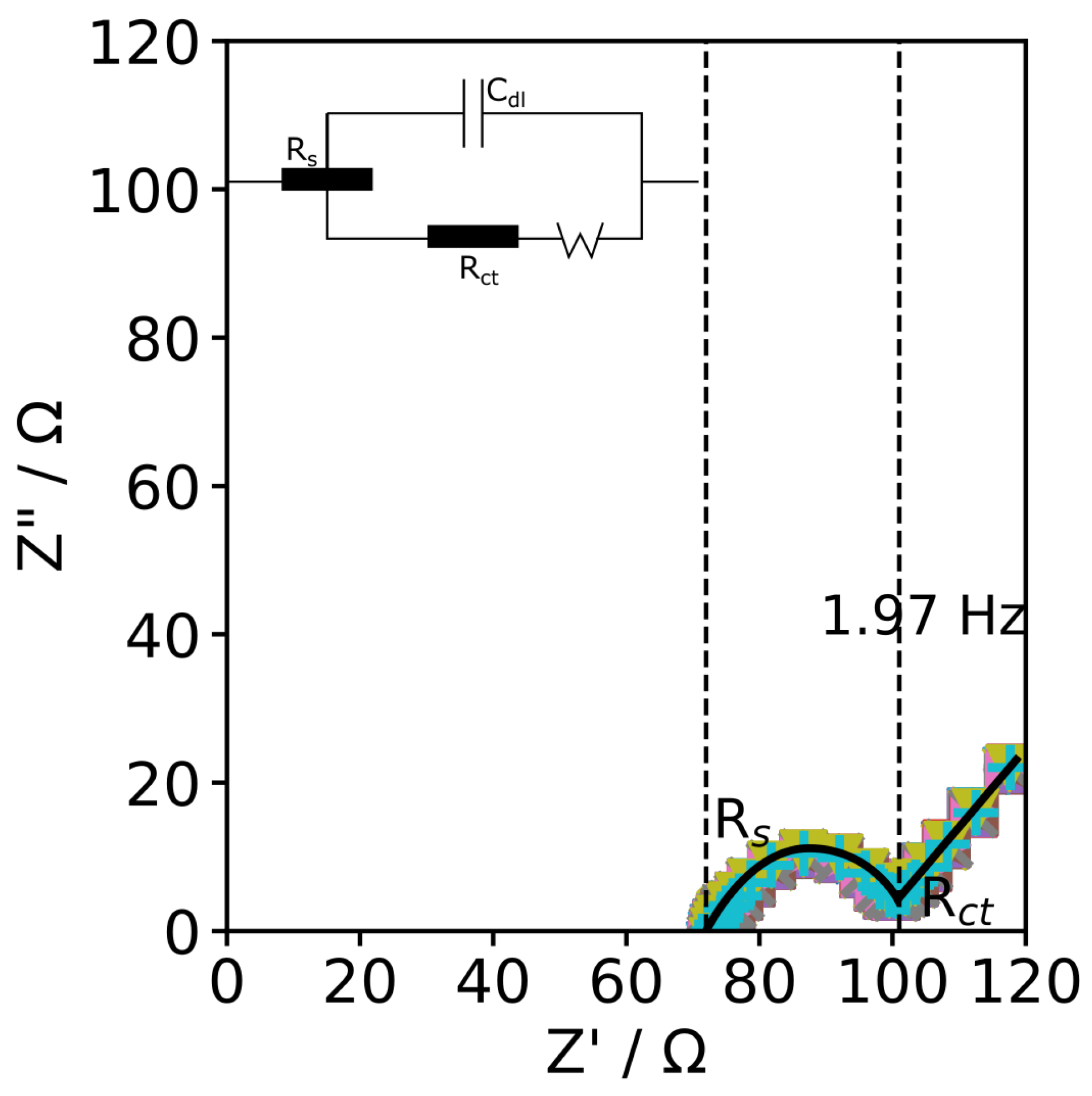
3.2. Characterisation of CFMB Electrode in Phosphate Buffer

Phosphate buffer is the most commonly used buffer for the investigation of electrochemical sensing, where neutral pH is required [1,3,4]. Therefore, CVs in 7.4 pH PB at different scan rates (10, 20, 50, 100, 200, and 400 mVs−1) were performed. The results of these scans are shown in Figure 3. An oxygen reduction peak can be observed at a voltage of −761 ± 72 mV (Figure 3a), which is related to the oxi-species (hydroxyl, carboxylic) on the carbon electrode [40].
From an electrochemistry point of view, the formal potential (E0) with a value of +14 mV was visible (in Figure 3b), similar to previously reported impurities appearing from the carbon fibre manufacturing process [41]. For comparison, the peak potential for the oxygen reduction at a scan rate of 100 mVs−1 for the CFMB electrode (−761 ± 72 mV) was over 100 mV more negative than that reported using the SPCE (−629 mV) in 0.1 M PB (pH 7.4) [[1]]. However, in the case where the potential window was limited from −300 mV to +800 mV, this additional redox process was not noticed (Figure 8) (in Section 3.5. Testing of Carbon Fibre Bundle Electrodes for Dopamine Detection).
A low electron-transfer resistance between oxygen-containing functionalities and the CFMB is suggested by the peak-to-peak separation ((ΔEp = Epa − Epc), in Figure 3b) values of 153 mV (measured at 10 mVs−1), similar to that reported for screen-printed carbon electrodes [40].
The oxygen possibly related to the above-mentioned functionalities was present in the EDX measurements represented in Figure 4, where the EDX spectra were measured at a 15 mV accelerating voltage, showing 96.5% of C and 3.5% of O present at the CFMB electrode. Representative EDX mapping images showed minor amounts of oxygen present (Figure 4b,d) with dominating amounts of carbon (Figure 4c,d) in the CFMB electrode.
In support of this hypothesis, the electrochemical impedance data (EIS) showed that the CFMB interface at higher frequencies acts as a resistor with total cell resistance Rs = 68.4 Ω (Figure 4a). This finding implies that the solution phase dominates the total cell resistance.
Additionally, the capacitance Cole–Cole plots (Figure 4b), where the imaginary (C″) versus the real (C′) part of the capacitance are plotted, provided information for the surface-confined redox species. By using the expressions of C′ = −Z”[(j2πfZ)−1] and C″ = −Z’[(j2πfZ)−1], where f is the frequency, the values of the real (C′) and imaginary (C″) parts of the complex capacitances can be ascertained. The output wave (Figure 4b) recorded at an OCP value of 14 mV comes from the pseudocapacitance (~48 μF) needed for charging the redox-active impurity layer.
Plotting C″ vs. frequency (Figure 5c) provided information about the associated relaxation time constant (τr−1), which was found to be 71 s−1 and is consistent with other studies where impurities were found to be present on the SPCE (τr−1 = 242 s−1), as reported previously [1].
The redox behaviour of the CFMB is evidence to suggest the presence of some redox molecules (e.g., 1,2-naphthoquinone) on the CFMB surface coming from the epoxide resin manufacturing process, in which the incorporation of quinone to the epoxy resins gives better mechanical properties to the fibre [42]. In support of this explanation, naphthoquinone functionalities are also found on commercial screen-printed electrodes (SPE) as an ink-binding compound [2].

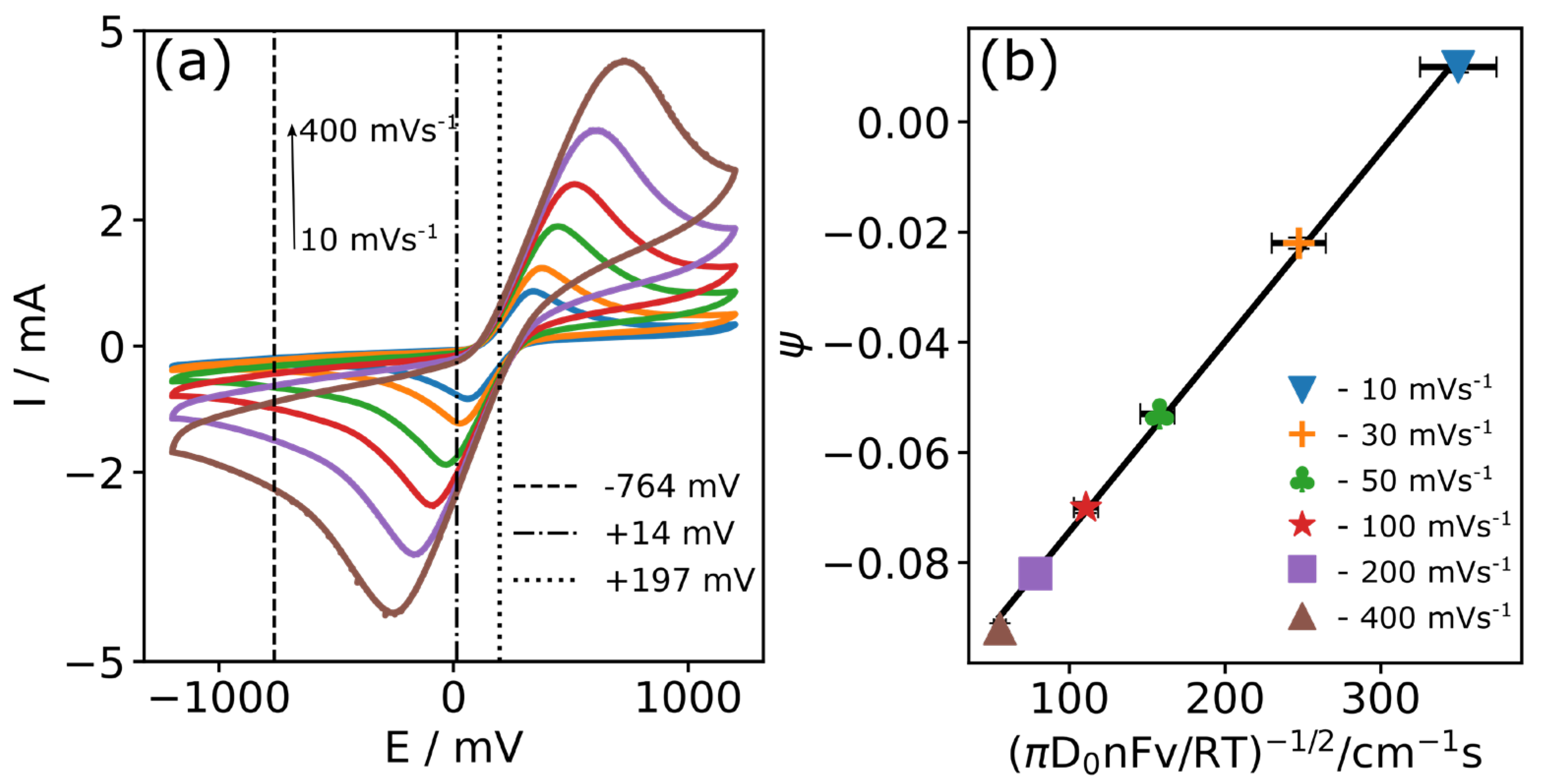
3.3. Characterisation of CFMB Electrode Using Ferrocene

In electrochemistry, ferrocene is most frequently used as the redox probe to investigate electron charge transfer when undertaking electrochemical analysis of sensor interfaces. Therefore, EIS was carried out in 2.5 mM [Fe(CN)6]3−/4− supported by 0.1 M PB (pH 7.4) at an OCP voltage of 197 mV, giving slightly higher values of Rs of 72.8 ± 0.1 Ω (at f = 50,549.29 Hz) (Figure 6a) than obtained in PB only (68.4 Ω).
Charge transfer resistance (Rct), the main parameter used in Faradaic impedance for interface characterisation, was observed at low frequency (f = 1.97 Hz), representing the diameter of the semicircle with a value of Rct = 101.4 ± 0.3 Ω (Randles equivalent circuit). For comparison, the ohmic resistance (R) of the CFMB electrode was calculated using the following equation: R = R0L0/r2π × N, where R0 is the resistivity of the carbon fibre roving and R0 = 16 µΩm (provided by the supplier). The calculated R was 55 ± 6.1 Ω, which is two times lower than the Rct value. The differences might be caused by additional resistance coming from the supporting electrolyte of 0.1 M PB.
The effect of changing the scan rate in 2.5 mM [Fe(CN)6]3−/4− supported by 0.1 M PB (pH 7.4) solution is shown in Figure 7a. The values of the CV peaks are summarised in Table 1. The average ratio of the anodic (Ipa) and cathodic (Ipc) peak currents (Ip) was 1.030 ± 0.051 for all scan rates investigated, and the peak currents and the peak voltages increased linearly with the square root of the scan rate (Figure 8b) with excellent R2 values of 0.999.
The value of ΔEp observed at the 100 mVs−1 scan rate was 609.6 ± 12.7 mV, which is significantly larger than the 57 mV expected for an ideally reversible couple. These observations are consistent with a quasi-reversible response that is influenced by heterogeneous electron transfer dynamics and is under semi-infinite linear diffusion control. In support of this, the process at lower frequency values (≤1.97 Hz) shows a slope with an angle of π/4, demonstrating a diffusion-limited process (Figure 6).
The diffusion coefficient (D0) was extracted by analysing the peak currents (Ip) obtained at several scan rates (from Figure 7a) according to the Randles–Sevcik equation D0 = Slope2RT/(0.217A2C2n3F3), where the slope represents the ratio of Ip to v (A (Vs−1)−1/2), n is the overall number of electrons in the electrochemical reaction (n = 1), F is the Faraday constant (96 485 C mol−1), C is the concentration of the electroactive species (2.5 × 10⁻⁶ mol cm−3), A is the geometrical electrode surface area (~3.7 cm2), v is the scan rate (V s−1), R is the gas constant (8.3145 J K−1mol−1), and T is the temperature (293 K).
The slope values (obtained from Figure 8a) were −6.36 × 10⁻³ ± 0.032 × 10⁻³ A (Vs−1)−1/2 and 7.12 ± 0.44 × 10⁻³ A (Vs−1)−1/2 for the Ipa and Ipc currents, respectively.
D0 was calculated as the average slope of Ipa and Ipc, giving a value of 6.66 ± 1.02 × 10⁻⁶ cm2s−1, which is similar to previously reported values of diffusion coefficients for ferrocene species measured on SPCE sensing interfaces [1,3].
Values of Ψ were determined for every scan rate from 10 to 400 mVs−1 (in Table 2) from Lavagnini’s equation Ψ = (−0.6288 + 0.0021X)/(1 − 0.017X), where X is ΔEp [43].
The rate constant indicates the rate at which electrons transfer between an electroactive species and an electrode surface [44]. The electrode material influences the overall rate of the electrochemical reaction and can even be used to estimate the allotrope of the carbon utilised. The heterogeneous electron transfer rate constant (k0) for the CFMB electrode was estimated using the slope of Ψ vs. (πD0nFv/RT)−1/2 in Figure 8b using the previously calculated value of D0. This estimation was performed using the Klingler—Kochi and Nicholson—Shain equation Ψ = k0(πD0nFv/RT)−1/2, where Ψ is the Nicholson’s kinetic parameter dependent on ΔEp (mV).
The k0 for the CFMB electrode was calculated to be relatively high for a non-modified CFMB electrode with a value of 3.45 ± 0.24 × 10⁻⁴ cms−1. For comparison, k0 values of the same order of magnitude for different types of carbon electrodes were obtained: GCE (k0 = 1.45 × 10⁻⁴ cms−1) [45], carbon paste (k0 = 3.6 × 10⁻⁴ cms−1) [46], and SPCE (k0 = 5.28 × 10⁻⁴ cms−1) [3] (Table 3). The two times lower k0 value for GCE and 1.5 times higher value of k0 for a SPCE ink electrode reported previously [3] might be explained by the variation in roughness factors between different carbon substrates. According to the literature, roughness analysis suggested that higher values of k0 are related to SPCEs with rougher carbon surfaces and, therefore, higher ink particle density [47]. Indeed, roughness factors of SPCEs have been calculated giving a value of 1.06 µm [47], which is much higher than for GCE at 1.5 nm [48] or for CFMB electrodes at 1.3 nm [18]. Also, the roughness of carbon surfaces has been suggested to increase up to 8.7 nm due to carbon oxidation in acidic or alkaline media [48]. Interestingly, the non-modified CFMB electrode showed relatively similar k0 values to the other kinds of carbon electrodes (summarised in Table 3).

3.4. Stability and Reproducibility of Carbon Fibre Bundle Electrodes

We investigated the reproducibility of the CFMB electrode, possibly effected by variation in the number of microcylinders in the bunch. CVs of six different CFMB electrodes in 0.1 M PB are shown in Figure 9 with a variety of background currents of less than 10% between the different electrodes.
For each electrode, the oxidative peak potential (Epc) remained at 517.7 ± 7.9 mV, and the reduction peak potential (Epa) remained at −91.9 ± 5.0 mV vs. Ag/AgCl. The forward oxidative peak current (Ipc) was 2.576 ± 0.010 mA, and the reduction peak current (Ipa) was −2.508 ± 0.028 mA within the same electrode and 2.676 ± 0.135 mA and −2.698 ± 0.164 mA between electrodes; this resulted in measurement errors of 0.38% (from Ipc) and 1.12% (from Ipa) within an electrode and 5.04% (from Ipc) and 6.07% (from Ipa) between electrodes, demonstrating good reproducibility between the electrodes. To provide further evidence for the electrode stability, the EIS (in Figure 6b) measurements showed negligible change in Rct values (at f = 1.97 Hz) within 0.29% over 20 scans, which is consistent with the stability obtained over CV cycling (0.38% (from Ipc)).

3.5. Testing of Carbon Fibre Bundle Electrodes for Dopamine Detection

In order to mimic the environment in the human body, a pH of 7.4 was maintained as the condition for the determination of dopamine (DA). CVs of dopamine on a non-modified CFMB electrode in pH 7.4 PB are shown in Figure 10a. The potential window was limited to avoid oxygen evolution (appearing at −764 mV, as shown in Figure 3a). At 0 μM of DA, the CV does not show any apparent redox reaction in the potential window from −300 mV to +800 mV. After the addition of 10 μM of DA, a wave in the oxidation and reduction regions appeared, demonstrating one-electron oxidation of DA similar to that reported previously [49]. With a higher DA concentration, an oxidation peak for DA at +397 ± 31 mV vs. Ag/AgCl was obtained, demonstrating a similar value as previously reported on GC at +310 mV and SPCE at +370 mV [49].
The increase in Itarget was normalised as RR%(%) = (Itarget − Iblank)/Iblank × 100, where Itarget is the value of the Ipc peak at DA concentration, and Iblank is the value of the current without DA. The Ipc current increased linearly within a range of concentrations of DA from 10 μM to 100 μM, and significantly, RR% of 600% at DA of 100 μM was reached with a sensitivity of 428 nAμM−1 (calculated as the slope of the calibration curve, Figure 10b).
Sensitivity is usually normalised to the area of the electrode [50]. Therefore, in the case of a packed electrode (Abulk = 0.008 cm2), the sensitivity could theoretically reach a value of 53.5 μA(μM)−1cm−2. Alternatively, in the case of an unpacked electrode (A = 3.7 cm2), the sensitivity might reach a value of 115.67 nA(μM)−1cm−2. The sensitivity to DA obtained in this work is of the same order of magnitude as for SPCE (~200 nA(μM)−1cm−2) [30] and 2D pyrolytic carbon electrodes (372 nA(μM)−1cm−2) [50] or porous 3D pyrolytic carbon nanograss (773 nA(μM)−1cm−2) [50].
As normalised sensitivity is very dependent on the area of the electrode under consideration, limit-of-detection (LOD) was used to compare the sensitivities between the different platforms. The LOD of the DA was determined according to LOD = 3σ/slope, where σ is the standard deviation of the y-intercept of the standard plot (RR(%) vs. target concentration) [51]. The LOD of the proposed CFMB electrodes for the measurement of DA was determined to be 8.85 μM, which is of the same magnitude as various non-modified SPCE electrodes (LOD = 4.8 μM) and 3D-printed carbon—polylactic acid electrodes (LOD = 4.0 μM) [52]. Also, the LOD value achieved on the non-modified CFMB reported here is of the same order of magnitude as various state-of-the-art modified electrodes, for example, reduced graphene oxide modified GCE (LOD = 6 μM) [53], and glycine (LOD = 1.8 μM) [54] and aspartic acid (LOD = 1.2 μM) [54] grafted GCE.
Despite the simplicity of the CFMB electrodes integrated into the 3D-printed cell, relevant results for electrochemical DA detection (LOD = 8.85 μM, R2 = 0.978, N = 10) were demonstrated without any modification or pre-treatment of the electrodes.
Electrode fouling is a common problem in electrochemical sensing and can be caused by a variety of factors. In the case of DA detection, fouling of the electrode can be caused by the oxidation of DA and its products [55]. This can cause the electrode to become coated with a layer of contaminants, which can reduce its sensitivity and range of detection and can also cause the electrode to become unstable over time.
We were able to overcome this issue by using the CFME electrode for a single concentration of prepared dopamine (in an electrochemical cell as shown in Figure 1, 3D view), which we believe helped to achieve a wide range (up to 100 μM) and sensitive detection (LOD = 8.85 μM) of DA. This finding has the potential to improve the performance of electrochemical sensors for DA detection and could enable the development of more sensitive and reliable sensors that are capable of detecting DA over a wide range of concentrations. Additionally, the use of non-modified carbon fibre bundles as electrodes could also make these sensors more cost-effective to produce, potentially making them more widely available for use in clinical and research settings.

3.6. Testing of Carbon Fibre Bundle Electrodes for Dopamine Selectivity

Electrochemical selectivity refers to the ability of a material to preferentially interact with or absorb certain molecules based on their electrochemical properties. This can be achieved using electrodes with different oxidation potentials, which are measures of the energy required to oxidise or reduce a molecule. Different molecules have different oxidation potentials, and an electrode with a certain oxidation potential will preferentially interact with molecules that have similar oxidation potentials.
Carbon fibres modified with chemical groups, such as amines or carboxyl groups, known as carbon fibre modified electrodes (CFMEs), can be used as electrodes with high electrochemical selectivity for dopamine. The presence of these chemical groups on the surface of the carbon fibres enables CFMEs to selectively interact with dopamine due to the similar oxidation potentials of these groups and dopamine (E0 = +140 mV). CFMEs with an epoxy sizing layer, known as carbon fibre modified electrodes with epoxy sizing layers (CFMBs), have improved electrochemical selectivity for dopamine compared to CFMEs without the epoxy sizing layer. The limit of detection (LOD) of CFMBs for dopamine was found to be 0.5 nM, indicating their ability to detect very low concentrations of dopamine. CFMBs could potentially be used to selectively detect other molecules with similar oxidation potentials to dopamine, such as serotonin (E0 = +150 mV) or norepinephrine (E0 = +220 mV).
Further research is needed to optimise the electrochemical selectivity of CFMBs for specific analytes and to investigate their potential applications in chemical sensing and other fields.

4. Conclusions

In summary, in this work, a non-modified commercial carbon fibre microcylinder bundle was electrochemically characterised as an electrode. The surface of the manufactured electrode was used without any additional treatment, activation, or modification. The heterogeneous rate constant obtained using cyclic voltammetry was 3.45 ± 0.24 × 10⁻⁴ cm·s−1; this is higher than the glassy carbon or carbon paste electrode heterogeneous rate constants reported in the literature. The linear range of dopamine detection on the carbon fibre microcylinder bundle sensor in neutral pH spanned from 0 to 100 μM with a sufficient LOD of 8.85 μM. This electrode could be applied for other analytes, such as ascorbic acid or glucose, and shows demonstrable promise as a simple and inexpensive disposable electrode. The use of carbon fibre microcylinder bundle electrodes is a new, alternative, and highly useful technique for electrochemical sensing.

Author Contributions

Conceptualization, A.E. and M.M.; methodology, A.J.; software, N.Z.; validation, A.S., A.B. and A.E.; formal analysis, M.M.; investigation, A.J.; resources, N.Z.; data curation, A.S.; writing—original draft preparation, A.B.; writing—review and editing, A.E.; visualization, M.M.; supervision, A.B.; project administration, A.B.; funding acquisition, A.B. All authors have read and agreed to the published version of the manuscript.

Funding

This research was funded by multiple sources. Ausra Baradoke is grateful for the funding received from the European Social Fund, grant number 09.3.3-LMT-K-712-23-0159, under a grant agreement with the Research Council of Lithuania (LMTLT). Mark Merzlikin, Alexandra Elsakova, and Ali Jafarov acknowledge the funding from the Estonian Science Foundation’s grants PRG1084 and PRG772, the IT Excellence Centre (EXCITE), and the Institutional Development Programme for Research and Development and Higher Education Institutions (ASTRA), grant number 2014-2020.4.01.16-0027. The authors also acknowledge facilities support from the Intelligent Materials and Systems Lab, Institute of Technology, University of Tartu.

Institutional Review Board Statement

Not applicable.

Informed Consent Statement

Not applicable.

Data Availability Statement

Data is unavailable due to privacy.

Acknowledgments

Ausra Baradoke is grateful to the European Social Fund (No. 09.3.3-LMT-K-712-23-0159) under a grant agreement with the Research Council of Lithuania (LMTLT). Mark Merzlikin, Alexandra Elsakova, and Ali Jafarov acknowledge the Estonian science foundation’s grants (PRG1084, PRG772), IT excellence centre (EXCITE), and the institutional development programme for research and development and higher education institutions (ASTRA, No. 2014-2020.4.01.16-0027). We acknowledge facilities support from the Intelligent Materials and Systems Lab, Institute of Technology, University of Tartu.

Conflicts of Interest

The authors declare no conflict of interest.

References

  1. Baradoke, A.; Hein, R.; Li, X.; Davis, J.J.J. Reagentless Redox Capacitive Assaying of C-Reactive Protein at a Polyaniline Interface. Anal. Chem. 2020, 92, 3508–3511. [Google Scholar] [CrossRef] [PubMed] [Green Version]
  2. Baradoke, A.; Pastoriza-Santos, I.; González-Romero, E. Screen-printed GPH electrode modified with Ru nanoplates and PoPD polymer film for NADH sensing: Design and characterization. Electrochim. Acta 2019, 300, 316–323. [Google Scholar] [CrossRef]
  3. Baradoke, A.; Jose, B.; Pauliukaite, R.; Forster, R.J. Properties of Anti-CA125 antibody layers on screen-printed carbon electrodes modified by gold and platinum nanostructures. Electrochim. Acta 2019, 306, 299–306. [Google Scholar] [CrossRef]
  4. Baradoke, A.; Santos, A.; Bueno, P.R.; Davis, J.J. Introducing polymer conductance in diagnostically relevant transduction. Biosens. Bioelectron. 2020, 172, 112705. [Google Scholar] [CrossRef]
  5. Tiwari, J.N.; Vij, V.; Kemp, K.C.; Kim, K.S. Engineered carbon-nanomaterial-based electrochemical sensors for biomolecules. ACS Nano 2016, 10, 46–80. [Google Scholar] [CrossRef] [Green Version]
  6. Drobysh, M.; Ramanavicius, A.; Baradoke, A. Science of the Total Environment Polyaniline-based electrochemical immunosensor for the determination of antibodies against SARS-CoV-2 spike protein. Sci. Total Environ. 2023, 862, 160700. [Google Scholar] [CrossRef]
  7. Schröder, P.; Schröder, P.; Schröder, P.; Aguiló-Aguayo, N.; Auer, A.; Grießer, C.; Kunze-Liebhaüser, J.; Ma, Y.; Hummel, M.; Obendorf, D.; et al. Activation of carbon tow electrodes for use in iron aqueous redox systems for electrochemical applications. J. Mater. Chem. C 2020, 8, 7755–7764. [Google Scholar] [CrossRef]
  8. Eyckens, D.J.; Arnold, C.L.; Simon, Ž.; Gengenbach, T.R.; Pinson, J.; Wickramasingha, Y.A.; Henderson, L.C. Covalent sizing surface modification as a route to improved interfacial adhesion in carbon fibre-epoxy composites. Compos. Part A Appl. Sci. Manuf. 2021, 140, 106147. [Google Scholar] [CrossRef]
  9. Castañeda, L.F.; Walsh, F.C.; Nava, J.L.; de León, C.P. Graphite felt as a versatile electrode material: Properties, reaction environment, performance and applications. Electrochim. Acta 2017, 258, 1115–1139. [Google Scholar] [CrossRef]
  10. Li, H.; Liebscher, M.; Ranjbarian, M.; Hempel, S.; Tzounis, L.; Schröfl, C.; Mechtcherine, V. Electrochemical modification of carbon fiber yarns in cementitious pore solution for an enhanced interaction towards concrete matrices. Appl. Surf. Sci. 2019, 487, 52–58. [Google Scholar] [CrossRef]
  11. Gajalakshmi, K.; Senthilkumar, N.; Mohan, B.; Anbuchezhiyan, G. An investigation on microstructure and mechanical behaviour of copper-nickel coated carbon fibre reinforced aluminium composites. Mater. Res. Express 2020, 7, 115701. [Google Scholar] [CrossRef]
  12. Budiyantoro, C.; Rochardjo, H.S.B.; Nugroho, G. Effects of processing variables of extrusion–pultrusion method on the impregnation quality of thermoplastic composite filaments. Polymers 2020, 12, 2833. [Google Scholar] [CrossRef] [PubMed]
  13. Xie, S.; Liu, S.; Cheng, P.F.; Lu, X. Recent Advances toward Achieving High-Performance Carbon-Fiber Materials for Supercapacitors. ChemElectroChem 2018, 5, 571–582. [Google Scholar] [CrossRef]
  14. Jamal, M.; Sarac, A.S.; Magner, E. Conductive copolymer-modified carbon fibre microelectrodes: Electrode characterisation and electrochemical detection of p-aminophenol. Sens. Actuators B Chem. 2004, 97, 59–66. [Google Scholar] [CrossRef]
  15. Sugawara, K.; Yugami, A.; Kojima, A. Voltammetric detection of biological molecules using chopped carbon fiber. Anal. Sci. 2010, 26, 1059–1063. [Google Scholar] [CrossRef] [PubMed]
  16. Ngamchuea, K.; Lin, C.; Batchelor-Mcauley, C.; Compton, R.G. Supported Microwires for Electroanalysis: Sensitive Amperometric Detection of Reduced Glutathione. Anal. Chem. 2017, 89, 3780–3786. [Google Scholar] [CrossRef] [PubMed]
  17. Vara, H.; Collazos-Castro, J.E. Biofunctionalized Conducting Polymer/Carbon Microfiber Electrodes for Ultrasensitive Neural Recordings. ACS Appl. Mater. Interfaces 2015, 7, 27016–27026. [Google Scholar] [CrossRef]
  18. Moosburger-Will, J.; Bauer, M.; Schubert, F.; Kunzmann, C.; Lachner, E.; Zeininger, H.; Maleika, M.; Hönisch, B.; Küpfer, J.; Zschoerper, N.; et al. Methyltrimethoxysilane plasma polymerization coating of carbon fiber surfaces. Surf. Coat. Technol. 2017, 311, 223–230. [Google Scholar] [CrossRef]
  19. Sharp, D.; Gladstone, P.; Smith, R.B.; Forsythe, S.; Davis, J. Approaching intelligent infection diagnostics: Carbon fibre sensor for electrochemical pyocyanin detection. Bioelectrochemistry 2010, 77, 114–119. [Google Scholar] [CrossRef]
  20. Anderson, A.; Phair, J.; Benson, J.; Meenan, B.; Davis, J. Investigating the use of endogenous quinoid moieties on carbon fibre as means of developing micro pH sensors. Mater. Sci. Eng. C 2014, 43, 533–537. [Google Scholar] [CrossRef]
  21. Ezekiel, H.B.; Sharp, D.; Villalba, M.M.; Davis, J. Laser-anodised carbon fibre: Coupled activation and patterning of sensor substrates. J. Phys. Chem. Solids 2008, 69, 2932–2935. [Google Scholar] [CrossRef] [Green Version]
  22. Li, G.; Wu, J.; Qi, X.; Wan, X.; Liu, Y.; Chen, Y.; Xu, L. Molecularly imprinted polypyrrole film-coated poly(3,4-ethylenedioxythiophene):polystyrene sulfonate-functionalized black phosphorene for the selective and robust detection of norfloxacin. Mater. Today Chem. 2022, 26, 101043. [Google Scholar] [CrossRef]
  23. Xia, Y.; Li, G.; Zhu, Y.; He, Q.; Hu, C. Facile preparation of metal-free graphitic-like carbon nitride / graphene oxide composite for simultaneous determination of uric acid and dopamine. Microchem. J. 2023, 190, 108726. [Google Scholar] [CrossRef]
  24. Bismarck, A.; Lee, A.F.; Saraç, A.S.; Schulz, E.; Wilson, K. Electrocoating of carbon fibres: A route for interface control in carbon fibre reinforced poly methylmethacrylate? Compos. Sci. Technol. 2005, 65, 1564–1573. [Google Scholar] [CrossRef]
  25. Yang, Z.; Peng, H.; Wang, W.; Liu, T. Crystallization behavior of poly(ε-caprolactone)/layered double hydroxide nanocomposites. J. Appl. Polym. Sci. 2010, 116, 2658–2667. [Google Scholar] [CrossRef]
  26. Ates, M.; Uludag, N.; Sarac, A.S. Electrochemical impedance of poly(9-tosyl-9H-carbazole-co-pyrrole) electrocoated carbon fiber. Mater. Chem. Phys. 2011, 127, 120–127. [Google Scholar] [CrossRef]
  27. Ates, M.; Yilmaz, K.; Shahryari, A.; Omanovic, S.; Sarac, A.S. A study of the electrochemical behavior of poly [N-Vinyl carbazole] formed on carbon-fiber microelectrodes and its response to dopamine. IEEE Sens. J. 2008, 8, 1628–1639. [Google Scholar] [CrossRef]
  28. Gerhardt, G.A.; Oke, A.F.; Nagy, G.; Moghaddam, B.; Adams, R.N. Nafion-coated electrodes with high selectivity for CNS electrochemistry. Brain Res. 1984, 290, 390–395. [Google Scholar] [CrossRef] [PubMed]
  29. Sarac, A.S.; Sezgin, S.; Ates, M.; Turhan, C.M. Electrochemical impedance spectroscopy and morphological analyses of pyrrole, phenylpyrrole and methoxyphenylpyrrole on carbon fiber microelectrodes. Surf. Coat. Technol. 2008, 202, 3997–4005. [Google Scholar] [CrossRef]
  30. Cumba, L.R.; Camisasca, A.; Giordani, S.; Forster, R.J. Electrochemical Properties of Screen-Printed Carbon Nano-Onion Electrodes. Molecules 2020, 25, 3884. [Google Scholar] [CrossRef]
  31. Wang, Y.; Tong, Q.; Ma, S.R.; Zhao, Z.X.; Pan, L.B.; Cong, L.; Han, P.; Peng, R.; Yu, H.; Lin, Y.; et al. Oral berberine improves brain dopa/dopamine levels to ameliorate Parkinson’s disease by regulating gut microbiota. Signal Transduct. Target. Ther. 2021, 6, 77. [Google Scholar] [CrossRef]
  32. Elton, A.; Faulkner, M.L.; Robinson, D.L.; Boettiger, C.A. Acute depletion of dopamine precursors in the human brain: Effects on functional connectivity and alcohol attentional bias. Neuropsychopharmacology 2021, 46, 1421–1431. [Google Scholar] [CrossRef] [PubMed]
  33. Ferlazzo, A.; Espro, C.; Iannazzo, D.; Bonavita, A.; Neri, G. Yttria-zirconia electrochemical sensor for the detection of tyrosine. Mater. Today Commun. 2023, 35, 106036. [Google Scholar] [CrossRef]
  34. Xu, Z.; Qiao, X.; Tao, R.; Li, Y.; Zhao, S.; Cai, Y.; Luo, X. Biosensors and Bioelectronics A wearable sensor based on multifunctional conductive hydrogel for simultaneous accurate pH and tyrosine monitoring in sweat. Biosens. Bioelectron. 2023, 234, 115360. [Google Scholar] [CrossRef] [PubMed]
  35. Gan, A.W. Ion transfer voltammetry of amino acids with an all-solid-state ion-selective electrode for non-destructive phenylalanine sensing. Electroanalysis 2023, 35, e202200501. [Google Scholar] [CrossRef]
  36. Ferlazzo, A.; Espro, C.; Iannazzo, D.; Neri, G. Determination of Phenylalanine by a Novel. IEEE Trans. Instrum. Meas. 2023, 72, 1–8. [Google Scholar] [CrossRef]
  37. Maria, A.; Martins, G.; Wilkins, M.D.; Ligler, F.S.; Daniele, M.A.; Freytes, D.O. Microphysiological System for High-Throughput Computer Vision Measurement of Microtissue Contraction. ACS Sens. 2021, 6, 985–994. [Google Scholar] [CrossRef]
  38. Baradoke, A.; Juodkazyte, J.; Masilionis, I.; Selskis, A.; Pauliukaite, R.; Valiokas, R. Combined soft lithographic and electrochemical fabrication of nanostructured platinum microelectrode arrays for miniaturized sensor applications. Microelectron. Eng. 2019, 208, 39–46. [Google Scholar] [CrossRef]
  39. Cėpla, V.; Rakickas, T.; Stankevičienė, G.; Mazėtytė-Godienė, A.; Baradokė, A.; Ruželė, Ž.; Valiokas, R. Photografting and Patterning of Poly(ethylene glycol) Methacrylate Hydrogel on Glass for Biochip Applications. ACS Appl. Mater. Interfaces 2020, 12, 32233–32246. [Google Scholar] [CrossRef]
  40. Šljukić, B.; Banks, C.E.; Compton, R.G. An overview of the electrochemical reduction of oxygen at carbon-based modified electrodes. J. Iran. Chem. Soc. 2005, 2, 1–25. [Google Scholar] [CrossRef]
  41. Dhakate, S.R.; Bahl, O.P. Effect of carbon fiber surface functional groups on the mechanical properties of carbon-carbon composites with HTT. Carbon 2003, 41, 1193–1203. [Google Scholar] [CrossRef]
  42. Santos Miranda, M.E.; Marcolla, C.; Rodriguez, C.A.; Wilhelm, H.M.; Sierakowski, M.R.; Belle Bresolin, T.M.; de Freitas, R.A. Chitosan and N-carboxymethylchitosan: I. The role of N-carboxymethylation of chitosan in the thermal stability and dynamic mechanical properties of its films. Polym. Int. 2006, 55, 961–969. [Google Scholar] [CrossRef]
  43. Nicholson, R.S. Theory and Application of Cyclic Voltammetry for Measurement of Electrode Reaction Kinetics. Anal. Chem. 1965, 37, 1351–1355. [Google Scholar] [CrossRef]
  44. Randviir, E.P. A cross examination of electron transfer rate constants for carbon screen-printed electrodes using Electrochemical Impedance Spectroscopy and cyclic voltammetry. Electrochim. Acta 2018, 286, 179–186. [Google Scholar] [CrossRef]
  45. Siraj, N.; Grampp, G.; Landgraf, S.; Punyain, K. Cyclic Voltammetric Study of Heterogeneous Electron Transfer Rate Constants of Various Organic Compounds in Ionic liquids: Measurements at Room Temperature. Z. Für Phys. Chem. 2013, 227, 105–120. [Google Scholar] [CrossRef]
  46. Lavagnini, I.; Antiochia, R.; Magno, F. An Extended Method for the Practical Evaluation of the Standard Rate Constant from Cyclic Voltammetric Data. Electroanalysis 2004, 16, 505–506. [Google Scholar] [CrossRef]
  47. Fanjul-Bolado, P.; Hernández-Santos, D.; Lamas-Ardisana, P.J.; Martín-Pernía, A.; Costa-García, A. Electrochemical characterization of screen-printed and conventional carbon paste electrodes. Electrochim. Acta 2008, 53, 3635–3642. [Google Scholar] [CrossRef]
  48. Yi, Y.; Weinberg, G.; Prenzel, M.; Greiner, M.; Heumann, S.; Becker, S.; Schlögl, R. Electrochemical corrosion of a glassy carbon electrode. Catal. Today 2017, 295, 32–40. [Google Scholar] [CrossRef]
  49. Khan, A.F.; Brownson, D.A.C.; Randviir, E.P.; Smith, G.C.; Banks, C.E. 2D Hexagonal Boron Nitride (2D-hBN) Explored for the Electrochemical Sensing of Dopamine. Anal. Chem. 2016, 88, 9729–9737. [Google Scholar] [CrossRef] [Green Version]
  50. Asif, A.; Heiskanen, A.; Emnéus, J.; Keller, S.S. Pyrolytic Carbon Nanograss Electrodes for Electrochemical Detection of Dopamine. Electrochim. Acta 2021, 379, 138122. [Google Scholar] [CrossRef]
  51. Shrivastava, A.; Gupta, V. Methods for the determination of limit of detection and limit of quantitation of the analytical methods. Chron. Young Sci. 2011, 2, 21. [Google Scholar] [CrossRef]
  52. Richter, E.M.; Rocha, D.P.; Cardoso, R.M.; Keefe, E.M.; Foster, C.W.; Munoz, R.A.A.; Banks, C.E. Complete Additively Manufactured (3D-Printed) Electrochemical Sensing Platform. Anal. Chem. 2019, 91, 12844–12851. [Google Scholar] [CrossRef] [PubMed]
  53. How, G.T.S.; Pandikumar, A.; Ming, H.N.; Ngee, L.H. Highly exposed {001} facets of titanium dioxide modified with reduced graphene oxide for dopamine sensing. Sci. Rep. 2014, 4, 2–9. [Google Scholar] [CrossRef] [PubMed]
  54. Zhang, L.; Lin, X. Covalent modification of glassy carbon electrodes with glycine for voltammetric separation of dopamine and ascorbic acid. Anal. Bioanal. Chem. 2001, 370, 956–962. [Google Scholar] [CrossRef] [PubMed]
  55. Emadoddin, M.; Mozaffari, S.A.; Ebrahimi, F. An antifouling impedimetric sensor based on zinc oxide embedded polyvinyl alcohol nanoplatelets for wide range dopamine determination in the presence of high concentration ascorbic acid. J. Pharm. Biomed. Anal. 2021, 205, 114278. [Google Scholar] [CrossRef]
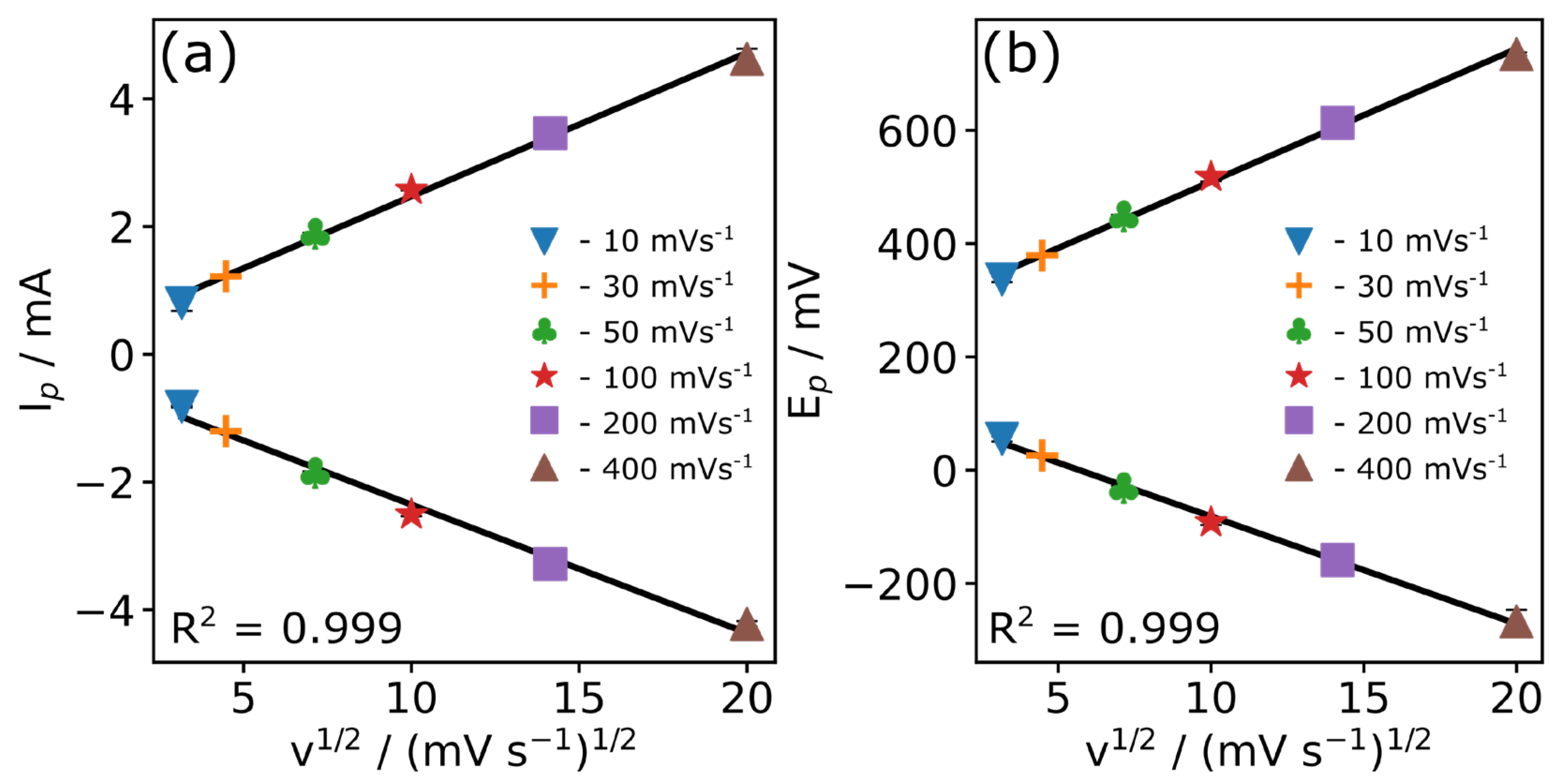
Figure 1. Design of electrochemical setup used for CFMB electrodes. (a) The size of the 3D-printed cap (S1 = 26 mm, S2 = 44 mm, a1 = 3 mm, a2 = 6 mm) and electrochemical cell (3D view) after loading CFMB electrodes (pseudo-coloured in green) for studies of [Fe(CN)6]3−/4− and DA. (b) Simulated view of CFMB area accessible for sensing with a length of the electrode L = 2 × 10⁻² m and radius r = 3.5 × 10⁻⁶ m; CFMB electrode is shown in packed and unpacked mode.
Coatings 13 01372 g001
Figure 2. SEM analysis of chopped carbon fibre microcylinder bundle at different magnifications. (a) 500×, (b) 1000×, (c) 2500×, and (d) 10,000× showing the cross-section of the carbon fibre microcylinder unit.
Coatings 13 01372 g002
Figure 3. (a) CVs of the CFMB electrode in 0.1 M of PB (pH 7.4) from −1200 mV to 1200 mV vs. Ag/AgCl at different scan rates (10, 50, 100, 200, 400 mVs−1), OCP (14 mV). (b) An enlarged area of the CVs showing surface confined redox species on the CFMB electrode; the inset shows the structure of 1,2-naphthoquinone.
Coatings 13 01372 g003
Figure 4. (a) EDX spectra measured at a 15 mV accelerating voltage showing C (96.5%) and O (3.5%) present at the CFMB electrode. Representative EDX mapping images showing (b) oxygen, (c) carbon, and a (d) view of the oxygen (pseudo coloured in green) and carbon (pseudo coloured in red).
Coatings 13 01372 g004
Figure 5. (a) Nyquist plot in 0.1 M PB from 100,000 Hz to 0.1 Hz, the amplitude of 10 mV at OCP (at 14 mV); the inset shows a ‘zoomed-in’ area of the plot at high frequencies highlighting the position of Rs in 0.1 M PB appearing from impurities (1,2-naphthoquinone) of the CFMB electrode. (b) Cole–Cole plots showing pseudo redox capacitance of the porous redox-active layer. (c) C″ plots vs. frequency showing the position of the relative time constant, τr−1. Inset shows the equivalent circuit used to obtained values of Rs.
Coatings 13 01372 g005
Figure 6. EIS Nyquist plots of the CFMB electrode in 2.5 mM [Fe(CN)6]3−/4− supported by 0.1 M PB from 100,000 Hz to 0.1 Hz at OCP voltage (197 mV), where Rct can be resolved as the diameter of the semicircular region showing temporal stability of Rct within RSD of ≤0.3% (20 tests). Inset is the Randles equivalent circuit used to obtain the values of Rs and Rct.
Coatings 13 01372 g006
Figure 7. (a) CVs of the CFMB electrode in 2.5 mM [Fe(CN)6]3−/4− supported by 0.1 M PB from −1200 mV to 1200 mV vs. Ag/AgCl at different scan rates. (b) Plots of the Nicholson’s kinetic parameter vs. [πD0nvF/(RT)]−1/2 and the calibrations for the CFMB electrode (error bars are 7.02% of [πD0nvF/(RT)]−1/2 value).
Coatings 13 01372 g007
Figure 8. Graphs obtained from different scan rate CVs in 2.5 mM [Fe(CN)6]3−/4− supported by 0.1 M PB. (a) The dependence of the peak current on the square root of the scan rate; (b) Dependence of the peak potential on the square root of the scan rate. The error bar is smaller than the data symbol.
Coatings 13 01372 g008
Figure 9. CVs in 0.1 M PB at 100 mVs−1; the CVs (3rd cycle) obtained from 6 different electrodes in the 3D-printed electrochemical cell.
Coatings 13 01372 g009
Figure 10. Test of the CFMB electrode for DA determination in 0.1 M 7.4 pH PB from −300 mV to 800 mV vs. Ag/AgCl: (a) CVs before and after addition of DA from 0 μM to 100 μM in steps of 10 μM, scan rate of 100 mVs−1; (b) Calibration curve of DA obtained from CV (R2 = 0.978).
Coatings 13 01372 g010
Table 1. CV potentials and current peaks per scan rate from Figure 7, stdev calculated from 3 cycles measurements.
v (mV s−1)Epa (mV)Epc (mV)Ipa (mA)Ipc (mA)
1055.2 ± 4.6336.9 ± 5.1−0.821 ± 0.0150.803 ± 0.125
2025.9 ± 0.1378.9 ± 1.6−1.205 ± 0.0211.221 ± 0.023
50−31.7 ± 4.0447.9 ± 2.7−1.858 ± 0.0251.887 ± 0.016
100−91.9 ± 5.0517.7 ± 7.9−2.508 ± 0.0282.576 ± 0.010
200−158.7 ± 11.4613.3 ± 16.2−3.283 ± 0.0283.463 ± 0.052
400−267.1 ± 20.5734.4 ± 3.0−4.222 ± 0.0444.627 ± 0.157
Table 2. The values of electrochemical parameters calculated from Figure 8, stdev calculated from 3 cycles measurements.
v (mV s−1)ΔEp (mV)E0 (mV)−Ipc/Ipa(πD0nFv/RT)−1/2Ψ
10281.7 ± 2.1196.1 ± 4.8 0.976 ± 0.138349.845 ± 24.5600.010 ± 0.001
20353.0 ± 1.7202.4 ± 0.81.013 ± 0.004247.378 ± 17.367−0.022 ± 0.001
50479.6 ± 1.7208.1 ± 3.31.016 ± 0.005156.455 ± 10.984−0.053 ± 0.001
100609.6 ± 12.7212.9 ± 2.01.027 ± 0.015110.631 ± 7.767−0.070 ± 0.001
200772.1 ± 25.7227.3 ± 5.71.055 ± 0.02578.228 ± 5.492−0.082 ± 0.002
4001001.5 ± 19.8233.7 ± 10.81.096 ± 0.04855.315 ± 3.883−0.092 ± 0.001
Table 3. Summary of heterogeneous electron transfer rate constants on different carbon electrodes.
Electrodek0/x 10−4 cms−1 Ref.
GCE1.45[45]
Carbon paste3.60[46]
SPCE5.28[3]
CFMB3.45This work
Disclaimer/Publisher’s Note: The statements, opinions and data contained in all publications are solely those of the individual author(s) and contributor(s) and not of MDPI and/or the editor(s). MDPI and/or the editor(s) disclaim responsibility for any injury to people or property resulting from any ideas, methods, instructions or products referred to in the content.

