Article

A Study on Poly(ethylene oxide)-Based Supercapacitors Doped with Various Dopants

School of Fashion & Textiles, The Hong Kong Polytechnic University, Hong Kong, China
*
Author to whom correspondence should be addressed.
Coatings 2023, 13(8), 1373; https://doi.org/10.3390/coatings13081373
Submission received: 7 May 2023 / Revised: 18 June 2023 / Accepted: 4 July 2023 / Published: 4 August 2023
(This article belongs to the Special Issue New Trends in Functional Materials and Devices)

Abstract

:
In this study, different concentrations of lithium perchlorate (LiClO4) and various types of nanocarbons were applied to form poly(ethylene oxide) (PEO)-based electrochemical double-layer (EDL) supercapacitors. For samples doped with various concentrations of LiClO4, 1 g/L of LiClO4 was prepared and mixed with PEO solution in different ratios for different concentrations of PEO:Li+ mixtures for further solution casting. It was found that the maximum current density and specific capacitance of the sample prepared under the ratio of 100:1 of PEO:Li+ were 1.84 μA/cm2 with a scanning rate of 100 mV/s and 33.56 nF/cm2 at 40 Hz, respectively. These were 10 times and nearly 18 times better than the control capacitor prepared without LiClO4. In addition, nanocarbons with four different structures, including mesoporous carbon nanopowders (Meso) and multi-walled (MW), double-walled (DW) and single-walled (SW) carbon nanotubes, were mixed with PEO solution to prepare samples via solution casting. The comparison of four types of nanocarbons showed that DW contributed the highest maximum current density and the specific capacitance at 10.51 μA/cm2 under a scanning rate of 100 mV/s and 32.798 nF/cm2 at 40 Hz, 60 times and 17 times higher than that of the control sample casted without any dopants.

1. Introduction

In the last few decades, substantial effort has been made for the development of different energy accommodation/alteration devices with promising energy and power densities, in order to address the rapid increase in ecological issues and the running out of a hydrocarbon deposit. Being part of a transitional system, dielectric capacitors, batteries and supercapacitors have drawn researchers’ attention because compared to secondary batteries, their power densities are higher. In addition, supercapacitors are free-for-maintenance, avoiding the memory effect, and can easily deal with a basic charging circuit. They are mostly safer than other devices because energy is stored in a physical form instead of a chemical form. This is the important reason why they can survive under a longer life cycle, and they can sustain a high rate of changing and discharging. As a result, supercapacitors have been largely applied in consumer electronics, vehicles operated under hybrid energy sources and energy management in different industries [1,2,3,4,5].
There are two energy storage mechanisms in supercapacitors: electrical double-layer (EDL) capacitance and pseudocapacitance. Recently, researchers have improved EDL capacitor performance by using activated carbon (AC) as the electrode material, which can provide a higher surface area; the capacitance benefits by the charge accumulated at the electrode/electrolyte interface. On the other hand, conducting polymers or metal oxides were used as the electrode material in pseudocapacitors, which facilitate reversible faradaic redox reactions. For example, polyanilines, a commonly used type of conducting polymer, have demonstrated high pseudocapacitance [6,7,8]. In specific energy, supercapacitors are several orders of magnitude higher than traditional capacitors like electrostatic capacitors and electrolytic capacitors. Moreover, the specific energy of supercapacitors is relatively lower than that of batteries, but the specific power of supercapacitors is higher than that of most batteries [4].
Furthermore, electro-textiles (e-textiles) like conducting fibres have become favourable materials in wearable and flexible applications due to being lightweight, bendable and durable. Textile products are now widely applied in manufacturing to produce functional clothes like medical monitoring accessories with variable sensors. Jost et al. have demonstrated the charge capability of carbon materials on various types of fabrics such as cotton lawn, polyester microfibre and nylon neoprene [9]. Additionally, Huang et al. have shown the viability of industrially weavable and knitted highly conductive yarns to become wearable textiles [10]. Moreover, Dong et al. have investigated the performance of activated carbon fibre cloth with carbon nanotubes and manganese dioxide under different bending conditions [11].
Currently, there are various techniques of coating metals on fabrics that are being used, like sputter coating, flame and arc spraying, vacuum deposition, conductive paints and lacquers and electroless plating. Among these methods, electroless plating is the most promising method for the metallisation of textiles due to its excellent conductivity, coherent metal deposition and compatibility with complex-shaped materials or insulators, and therefore this method can be applied for nearly all kinds of fibres. Moreover, it can be applied in various textile manufacturing stages like fibre, yarn, fabric and even garments [12].
With different conducting substrates like indium tin oxide (ITO) and conducting fabrics, stabilised polymeric electrolytes such as PEO and Poly(acrylonitrile) (PAN), and effective dopants like nanocarbons and lithium salts, researchers have constructed different types of EDL supercapacitors to explore the viability of different energy-storing devices. Some of this research has been summarised in Table 1 below.
To achieve the wearable and energy storage functions together, the electrode materials should be flexible and tough enough to sustain multiple bending. However, studies into polymeric EDL supercapacitors using wearable conducting fabrics as electrodes to collect energy are rarely found. To combine the advantages of supercapacitors and electro-textiles, in this study, electroless copper-plated flexible polyester fabrics were used, to be doped with various concentrations of LiClO4 and different forms of nanocarbons to form a series of stretchable and bendable supercapacitors, their electrical performances were then examined, and their electrical properties in different frequency ranges were studied. This fabric-based supercapacitor system is proposed to be used in the field of electro-textiles, which may be closely applied to human skin. Therefore, a solvent-free environment is safe to human users. In this study, water was used to dissolve LiClO4 and nanocarbons instead of using volatile organic solvents such as alcohols or ketones.

2. Experimental Methods

2.1. Polyester Fabric Metallisation

To prepare flexible conductive fabrics, commercial polyester fabrics with a density of 75 × 75 threads per sq. inch (poly(ethylene terephthalate), PET, as major component, by Lai Tak Enterprises Limited, Hong Kong, China) were down-sized into small pieces of 15 × 15 cm. Then, they were cleaned by Diadavin EWN 200% (by Bayer AG, Leverkusen, Germany), a non-ionic detergent diluted to 2% for 30 min at 30 °C and pH 7, to remove grease and make the fabric surface clean for chemical processes in later procedures. The metallisation of polyester fabrics is a four-step process: (a) surface modification; (b) activation; (c) electroless plating with Ni and (d) electroless plating with (Cu). After metallisation, plain polyester fabrics become conducting fabrics for further experimentation [12,18,19,20,21,22,23].
For surface modification, fabric pieces were dipped into sodium hydroxide (NaOH) solution at 50 °C, with a concentration of 4M, for 20 min. Chemical bonding in the backbone and branches of polyester on fabric surfaces were opened via the strong alkaline solution in this alkaline etching process. Therefore, surface roughness was enhanced and fabric surface area was increased, which could further benefit metal ion adhesion processes including palladium (Pd) coating and electroless Ni-plating. After alkaline etching, samples underwent acidification by dipping them into hydrochloric acid (HCl) at 25°C, with a concentration of 1%, for 30 s. In this stage, samples should not be washed with any solvents to keep the sample surface in an acidic state for further activation processes. Figure 1. has illustrated the flow of this surface activation process.
To activate and metallise the fabric surface, nucleation with catalytic treatment was carried out to facilitate the adhesion of the Pd atoms on the sensitised polyester fabric surface. In Figure 1, fabric samples were dipped into an acidic bath including Macuplex® activate D-34C (by MacDermid, Suwanee, GA, USA), Macuplex® 78 Sensitizer (by MacDermid, Suwanee, GA, USA), 37% HCl and deionised water with a volume percent of 0.59:1.96:21.57:75.88 for 3 min at room temperature. D-34C contains colloidal suspension of palladium particles in a stannous chloride (SnCl2) medium, which is an activating solution. The sensitiser is a formulated commercial product containing potassium iodate (KIO3) and potassium iodine (KI); with this combination, the bivalent tin (Sn2+) in this acidic environment can be preserved. Via this palladium–tin bath, surface sensitisation and activation take place; thus, tin (Sn) ions are transformed from Sn2+ to Sn4+, and further react with carboxylate functional groups which are negatively charged. Because of their ability regarding high metal ion adsorption, Pd ions can attach to Sn ions and function as a catalyst. To remove excess tin ions and those surrounding palladium ions on the fabric surfaces, fabric pieces were dipped into a sulphuric acid (H2SO4) bath at 50 °C, with a concentration of 50 g/L for 1 min.
A layer of nickel was plated on fabric surfaces via electroless Ni-plating, and an electroless Cu-plating process was later conducted on this Ni-plated fabric. To achieve this goal, the Pd-plated fabric pieces were dipped into a Ni-rich solution mixture consisting of ammonium hydroxide (NH4OH) with a concentration of 28%, Macuplex® J-61, Macuplex® J-60 and DI water with a volume percent of 0.5:3.0:10.0:86.5 for 3 min at 35 °C. J-61 is a reducing agent containing nickel and J-60 mainly consists of nickel chloride (NiCl2). In this Ni-rich solution mixture, Ni ions were attached to fabric surfaces with the Pd ions by recombining them with electrons; hence, these Ni ions were deposited and formed a thin conducting layer.
Nickel layer formation:  Ni2+ + 2e → Ni
After Ni-plating, fabric samples were connected to the cathode of the electrolytic bath for electroless Cu-plating, and a constant current source set at 3 ampere per square decimetre (ASD, A/dm2) was applied for 1 min at 50 °C for degreasing before electroless Cu-plating. After degreasing, the samples were dipped into a H2SO4 bath for 30 s at 50 °C to detach remnants of the oxide film and to activate fabric sample surfaces at the same time, and deionised water was used to rinse them afterwards. Eventually, fabrics were Cu-plated under 2 ASD at 50 °C, with non-cyanide alkaline copper strike for 6 min.

2.2. Fabrication of EDL Capacitors with Various Dopants

2.2.1. Preparation of Flexible Current-Collecting Polyester Fabrics

In this study, Cu-plated polyester fabrics were used to become current collectors in the EDL supercapacitor, and they were down-sized to 7.5 × 20 mm. Afterwards, these current-collecting substrates underwent solution casting with various PEO or PEO/dopant mixtures to form PEO active layers, by aligning them on the poly(tetrafluoroethylene) (PTFE) panel (provided by Goodfellow, Huntingdon, UK) uniformly.

2.2.2. Preparation of PEO Dielectric Spacer

To avoid thermal degradation and to make sure that PEO powder could be dissolved in the solution completely, 50 mL of deionised water was mixed with 1 g of PEO powder (Mv: 600,000, by Sigma-Aldrich, St. Louis, MA, USA) and stirred at room temperature. Afterwards, the dissolved PEO was spread on a glass panel and dried for 24 h under ambient temperature, and a 15 μm thick PEO layer was formed. This PEO layer was skinned off from the glass panel and this layer was trimmed into pieces of size 10 × 10 mm to be used as PEO spacers. These spacers were used as a dielectric material, which could isolate two active layers in this EDL supercapacitor.

2.2.3. Preparation of PEO:Li+ EDL Capacitors with Different LiClO4 Concentrations

The electrical properties of the PEO:Li+ EDL system with different concentrations of LiClO4 were determined in this study. Thus, solutions with different ratios of PEO and LiClO4 were formulated to prepare different EDL capacitors afterwards.
To prepare LiClO4 stock solution, 250 mL of deionised water was mixed with 250 mg of LiClO4 (99.99% trace metal basis, by Sigma-Aldrich, St. Louis, MA, USA). Additionally, to prepare different concentrations of PEO:Li+ solution, 50 ml of deionised water was mixed with 1 g PEO powder (Mv: 600,000, by Sigma-Aldrich, St. Louis, MA, USA) at room temperature. Afterwards, different amounts of LiClO4 stock solution were mixed into these PEO solutions with the ratio listed in Table 2 below.
Similarly to the preparation of PEO spacers, to avoid thermal degradation and to ensure that PEO powder would be dissolved completely in solutions, they were stirred thoroughly without heating. Subsequently, solutions were poured on the metallised polyester fabrics (Figure 2). To cast a uniform PEO:Li+ layer, the casted fabrics were put in an isolated box to dry for 24 h, which was connected to a low-throughput ventilation system with negative pressure. To guarantee that this layer could be formed with workable thickness and good adhesion, this process was replicated three times.
Once the polyester fabric surface had been casted with the PEO:Li+ layer, a previously prepared PEO spacer was sandwiched together with two pieces of casted fabric, as illustrated in Figure 3, to form an EDL capacitor. A capacitive effect was seen in the overlapping area of two PEO:Li+-casted fabrics. Then, the laminated supercapacitor was connected with wires on two metallised surfaces for further measurements.

2.2.4. Preparation of PEO:nanocarbon EDL Capacitors with Different Types of Nanocarbons

Electrical properties of PEO:nanocarbon EDL capacitors with various types of nanocarbons were determined in this study. To achieve this goal, different types of nanocarbons were mixed with PEO to form solutions for further sample fabrication.
Four types of nanocarbons were used in this study: (a) mesoporous carbon nanopowders (Meso); (b) multi-walled carbon nanotubes (MW); (c) double-walled carbon nanotubes (DW) and (d) single-walled carbon nanotubes (SW) (all nanopowders came from Sigma-Aldrich, St. Louis, MA, USA). Their specifications are listed in Table 3 below. For various nanocarbon solutions, 10 ml of deionised water was mixed with 40 mg of each type of nanocarbon to form solutions. Using an ultrasonic generator, these nanocarbon solutions were ultrasonically vibrated for two hours, to help these nanocarbons to be dispersed in solutions.
Once these solutions had been ultrasonically treated, 200 mg PEO powder in 10 ml of deionised water was mixed with various nanocarbon solutions and the proportion of PEO:nanocarbons in each solution was 5:1. To avoid thermal degradation, these solutions were comprehensively blended without heating, to make sure that the nanocarbons and PEO powder were dissolved uniformly in solutions. As shown in Figure 2, solutions were spread on metallised polyester fabrics attached to the PTFE panel. Samples were placed in an isolated box to dry for 24 h, which was connected to a low-throughput ventilation system with negative pressure. After the PEO:nanocarbon active layers had been casted, a previously prepared PEO spacer was sandwiched together with two pieces of casted fabric to form an EDL capacitor. A capacitive effect was seen in the stack of two casted pieces and the spacer in the overlapping area. Then, the laminated supercapacitor was connected with wires on two metallised surfaces for further measurements.

3. Results and Discussion

Recently, researchers have proposed various methods that can be used for preparing a capacitive coating layer on a conductive fabric surface, which is effective, thin and uniform for energy-storing purposes. Nevertheless, in the case of woven fabrics, deposition methods such as spin coating and chemical vapour deposition (CVD) will become less effective, owing to the fabric surface morphology. As the structure of woven fabrics consists of a number of horizontal and vertical yarns woven together to build up a large continuous plane, from a microscopic view, this woven surface consists of numbers of repeating peaks and troughs, and sometimes defects are found between junctions of yarns. These surface features usually worsen the uniformity of capacitive layer formation, since conductive materials may not be well deposited on the fabric surface due to the filling up of the pits. As a result, a discontinuous layer may be formed, which degrades the efficiency and effectiveness of the charge and discharging processes [24,25,26,27,28]. In this study, solution casting becomes a good candidate to apply on the metallised polyester fabric surface, to prepare a continuous PEO capacitive layer, due to its good adhesion and high flexibility.

3.1. Surface Morphology of Metallised Polyester Fabrics

Polyester fabrics were metallised via different chemical processes; via scanning electron microscopy (SEM), changes in the polyester fabric surfaces in different stages, starting from the untreated sample to the Cu-plating sample, were examined, and they are summarised in Figure 4.
In 
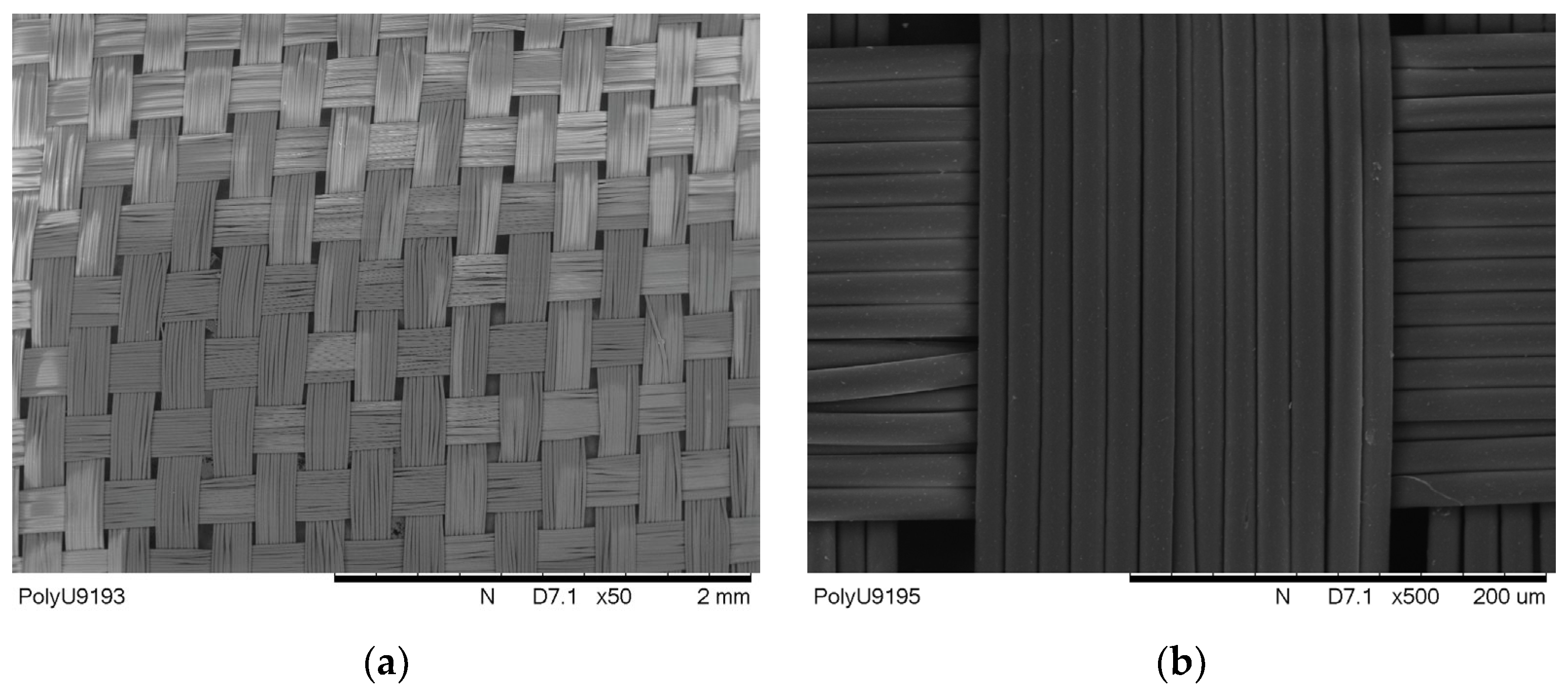
Figure 4a, the untreated polyester fabric has a uniform and clean surface, and as found via SEM estimation, the fibre diameter was 15 μm on average. 
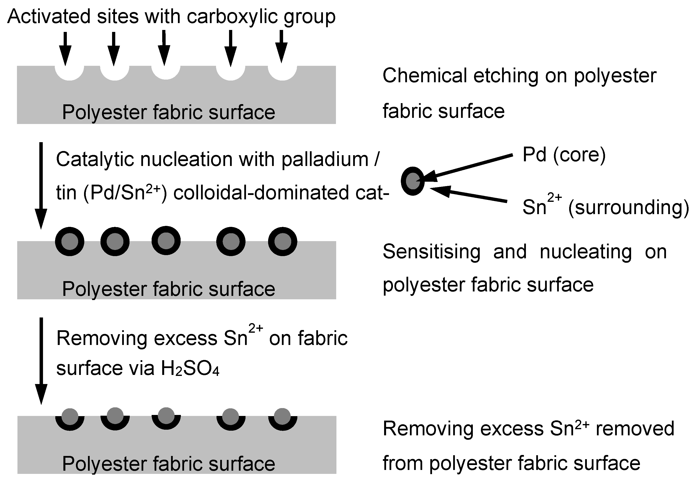
Figure 4b shows that the fabric sample was Pd-coated, a layer of Pd/Sn mixture was uniformly layered on the fibre surface and the diameter of the Pd-coated fibre was observed to be more or less the same as the untreated fibre, on average. After Ni-plating, as observed in Figure 4c, the fibre surface became shiny, as a layer of Ni had been plated on the fibre surface, and the average diameter of the fibre increased to about 17 μm. The SEM image shows that the estimated thickness of Ni-plating is in the range of the sub-micron (with a few hundred nm). Further, for electroless Cu-plating, a glossy metal coating is noticed on the fibre surface. This Cu coating formed around the fibre surface, as presented in Figure 4d. Via estimation, the Cu-plated polyester fibre diameter and the thickness of the Cu layer were about 20 μm and 1 μm, respectively. The estimated average fibre diameters in each stage are tabulated in Table 4.
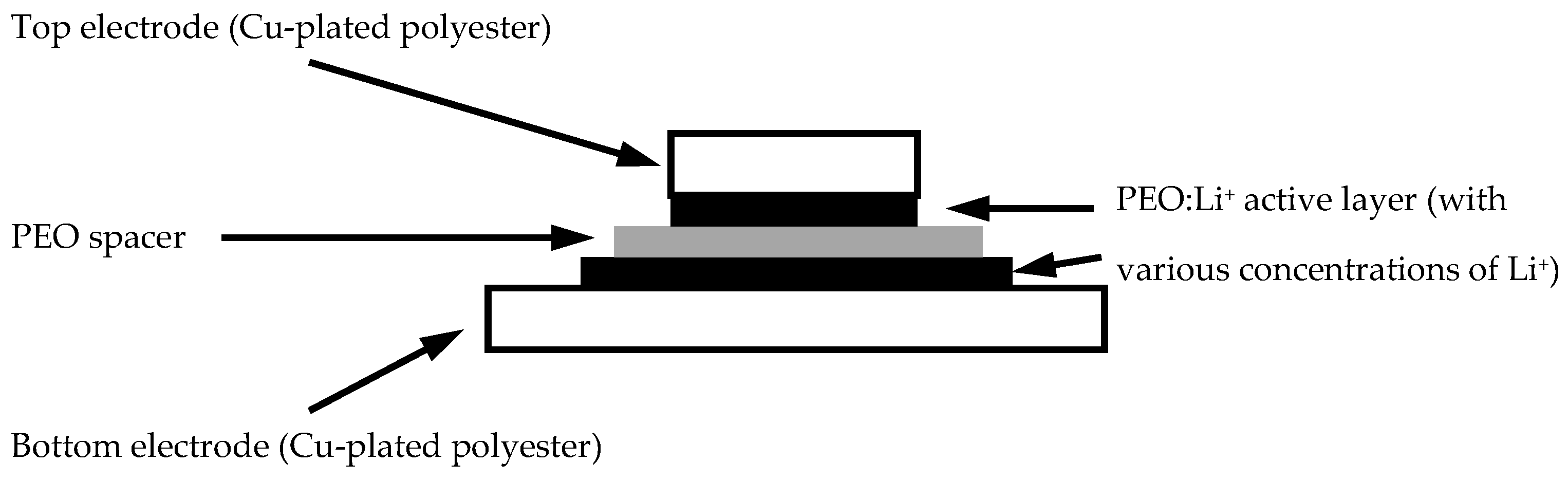
After a series of fabric metallisation processes, a PEO layer was casted on the metallised fabric surface. 
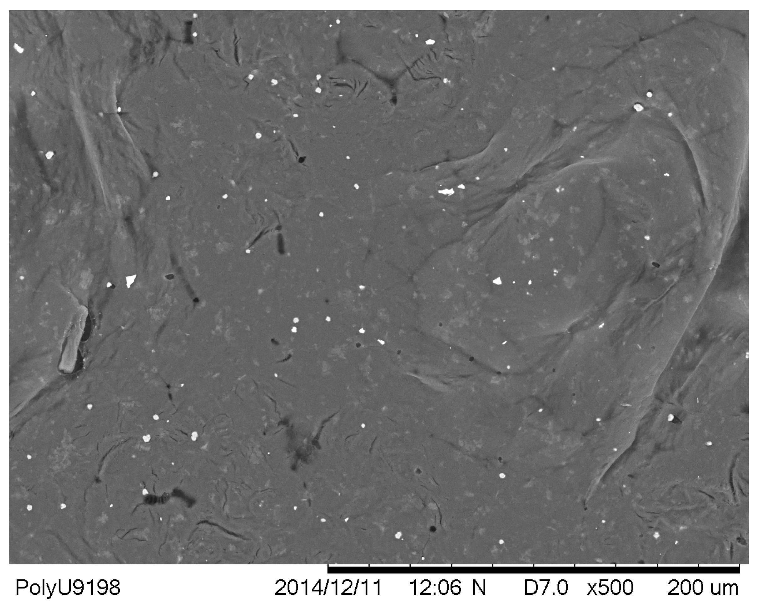
Figure 5 shows that a pure PEO layer was solution casted on the metallised polyester surface without any dopants. In the PEO layer, some particles of a white colour were found, which were crystallised PEOs that could be associated with different ionic dopants like lithium ions in a later part of the experiments, and therefore an efficient response of charging and discharging could be provided in different samples.
Commonly, the transportation of ions is usually related to ion hopping between ranges of adjacent sites in solid polymers. Via the motion of polymer chains, ions within the polymeric electrolyte in the amorphous phase can migrate in a dynamic environment at a temperature above the glass transition (Tg). Suitable coordination sites adjacent to ions are generated due to piston-like movement associated with short fragments of the polymer chains, and hence, the spontaneous hopping of ions can occur. However, if lots of atom motion in the polymer chain occurs in these segmental modes, their motions are usually slow. Therefore, the rate of ion hopping will be limited, and hence, the conductivity of the material will be affected. This mechanism becomes ineffective when crystallinity increases [29,30,31].
Nevertheless, the presence of crystallised sites in some linear polymers such as PEO can exhibit enhancement in ion transport efficiency in the polymer matrix if ionic dopants are present, as both mechanisms are concurrently present and competing in the PEO matrix. Therefore, the amorphous phase of the material will no longer dominate the conductivity of the PEO matrix [32,33].

3.2. Thickness Estimation of Different PEO-Casted Polyester Fabric Samples

Since PEO is an elastic and soft polymeric material, using the conventional mechanical contacting method to measure its thickness may not be the best way. Therefore, in this study, a non-contacting laser triangulation method was applied to measure various PEO-based spacers and electrolytic layers. Their thicknesses are presented in Table 5.

3.3. Frequency Responses of PEO-Based EDL Capacitors with Various LiClO4 Concentrations

Other than surface morphology, electrical properties of various EDL capacitors with different LiClO4 concentrations were examined. An impedance analyser ranging from 40 to 110 MHz was used to investigate the electrical properties of PEO-based samples, parameters involving series capacitance (Cs), the dissipation factor (D), series resistance (R), series reactance (X) and absolute impedance (|Z|), and the phase difference between the resistance and reactance (θ) was measured.
Various PEO-based supercapacitor samples were connected to the impedance analyser, their Cs were measured and their corresponding specific capacitance values were determined. Their specific capacitances at several testing frequencies (40, 1 K, 100 K and 100 MHz) are tabulated in 
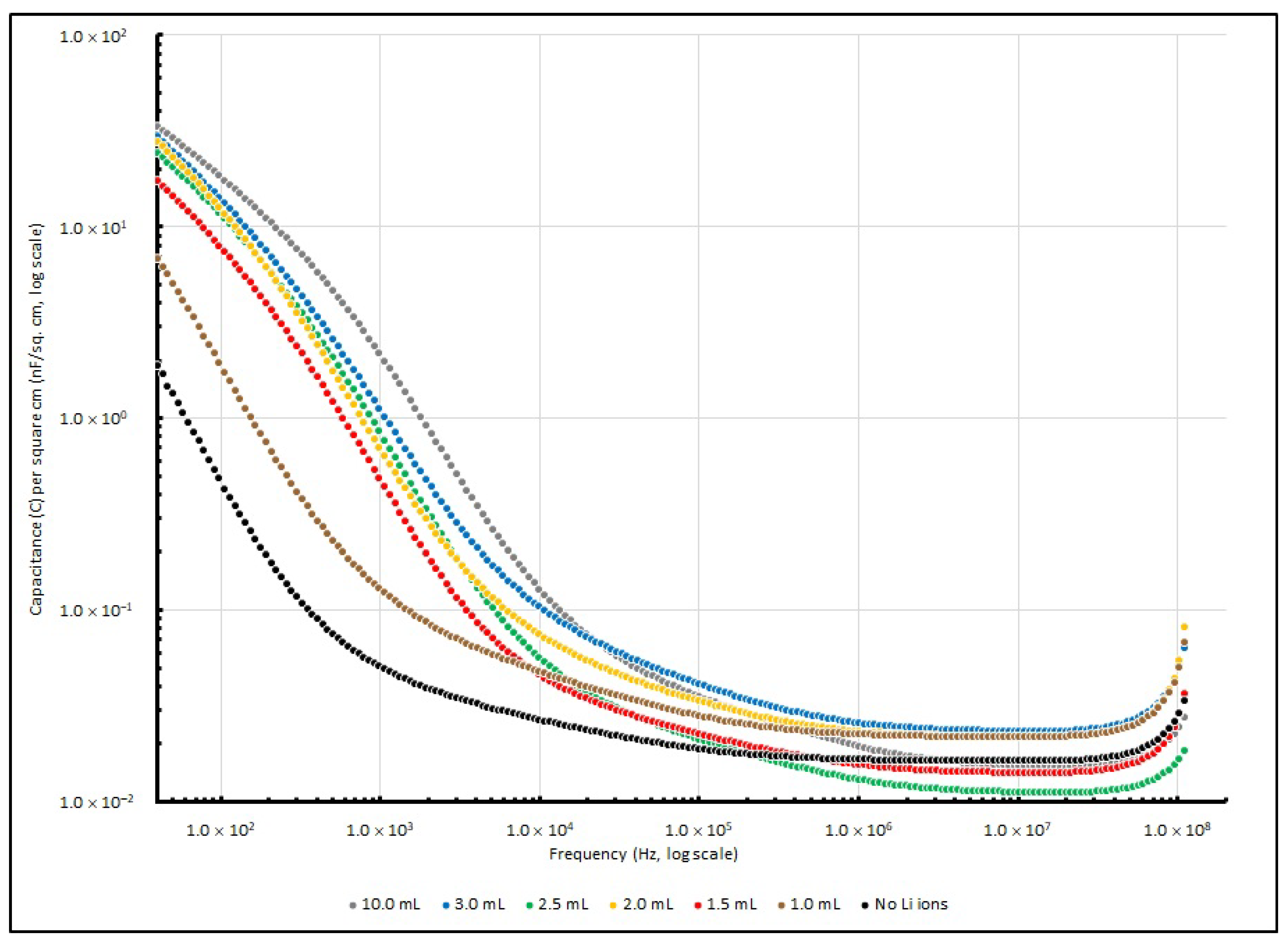
Table 6, while the changes in specific capacitance are illustrated in Figure 6.
At a lower frequency range (<1 kHz), the increase in Li+ ions determines the increase in specific capacitance of PEO-based samples. The control sample without any lithium ions exhibited a specific capacitance of 1.89 nF/cm2 at 40 Hz, and it was significantly increased by 263% to 6.86 nF/cm2 when the Li+ amount had raised to 1.0 ml; then, it eventually raised to 33.56 nF/cm2 after the Li+ amount was increased to 10.0 ml. When the frequency reached 1 kHz, the specific capacitances of the samples rose with the Li+ amount from 0.05 nF/cm2 (no Li+ added) to 0.12 nF/cm2 (1.0 ml) and reached 2.00 nF/cm2 (10.0 mL). Nevertheless, when the frequency was raised to 100 kHz or even higher, the effect from different amounts of LiClO4 became less significant, and the specific capacitance of the samples with different Li+ concentrations stayed at around 0.05 nF/cm2. Generally, PEO is a polymer that is neutral and non-charged. The polymer chains in it are well aligned, or in other words, it is highly crystalline. However, high crystallinity is not favourable for charges to migrate in the polymer matrix. Therefore, when dopants like Li+ ions are added into the PEO matrix, these ions will reduce the crystallinity of the matrix and the ionic conductivity will increase; hence, the charge storage capability will increase. When the Li+ concentration increased from 0.001 to 0.01, more ions were found in the PEO matrix, which contributed more to the conductivity of the ions, and the competence of the energy storage in the EDL capacitor system was enhanced. Therefore, the specific capacitance of the capacitor can be increased [34,
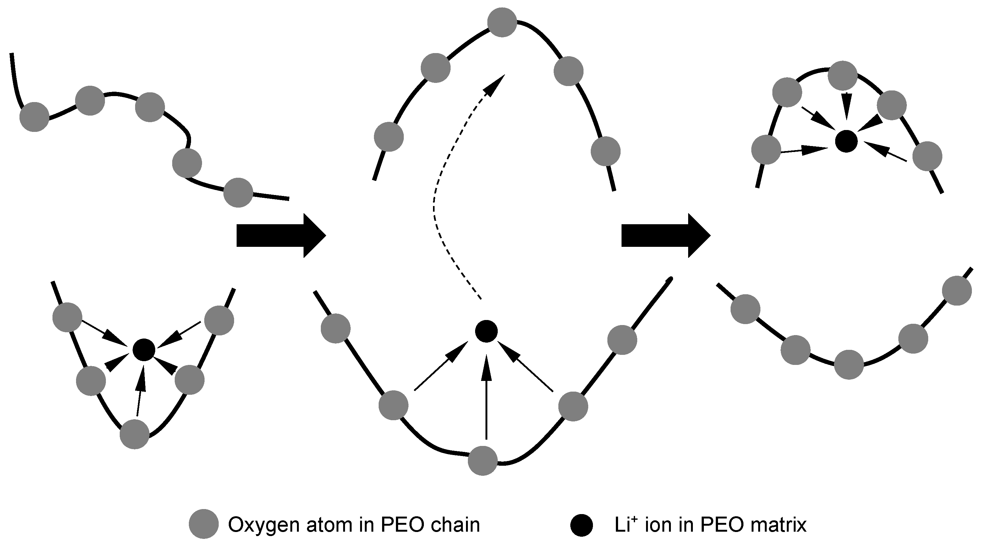
35]. As moieties are the main constitutive units in the oligoether structure, they are beneficial for the dissolving of alkali salts such as LiClO4, and they can be found in the backbone of polymer chains or their side branches. Additionally, the total lithium salt concentration in the PEO cast ruled the dissociation degree of the salt dissolved in it. Generally speaking, an increase in salt concentration gives a decrease in the dissociation degree. In some of the latest reports, an optimal salt concentration has been suggested by researchers, and lithium ions have been said to form complexes in linear oligo(ethylene oxide), such as PEO with oxygen (of ethylene oxide units) in a molar ratio of around 0.04. Moreover, some researchers have reported that molecular dynamic simulations show that in a PEO chain, approximately five ether oxygen molecules bond with a Li+ ion to form complexes, and this combination of molecules may hinder the mobility of cations. Therefore, Li+ ions’ mobility is highly dependent on the motions of Li+-containing complexation sites with PEO chains. The lithium ion motions between these complexation sites which are maintained by PEO matrix segmental motion are illustrated in Figure 7 [36].
On the other hand, in the capacitor, the dissipation factor (D) can be stated as follows:
D = R e q X c
where Xc is the capacitive reactance and Req is the equivalent resistance of the electrochemical system. Req signifies the capacitor loss which can be derived with physical origins in both dipole relaxation phenomena and the dielectric’s conduction electrons. The connection can be stated as follows:
R e q = σ ε ω 2 C
where ε is the lossless permittivity of the dielectric, C is the lossless capacitance of the dielectric material, σ is the dielectric material’s conductivity and ω is the angular frequency of the voltage applied into the electrochemical system. Meanwhile, Xc is related to
X c = 1 2 π f C = 1 ω C
where f is the sinusoid signal implemented into the measured EDL system. If Equations (2) and (3) are substituted into Equation (1), D can be expressed as follows:
D = σ ε ω
where D is a variable that is frequency-dependent. 
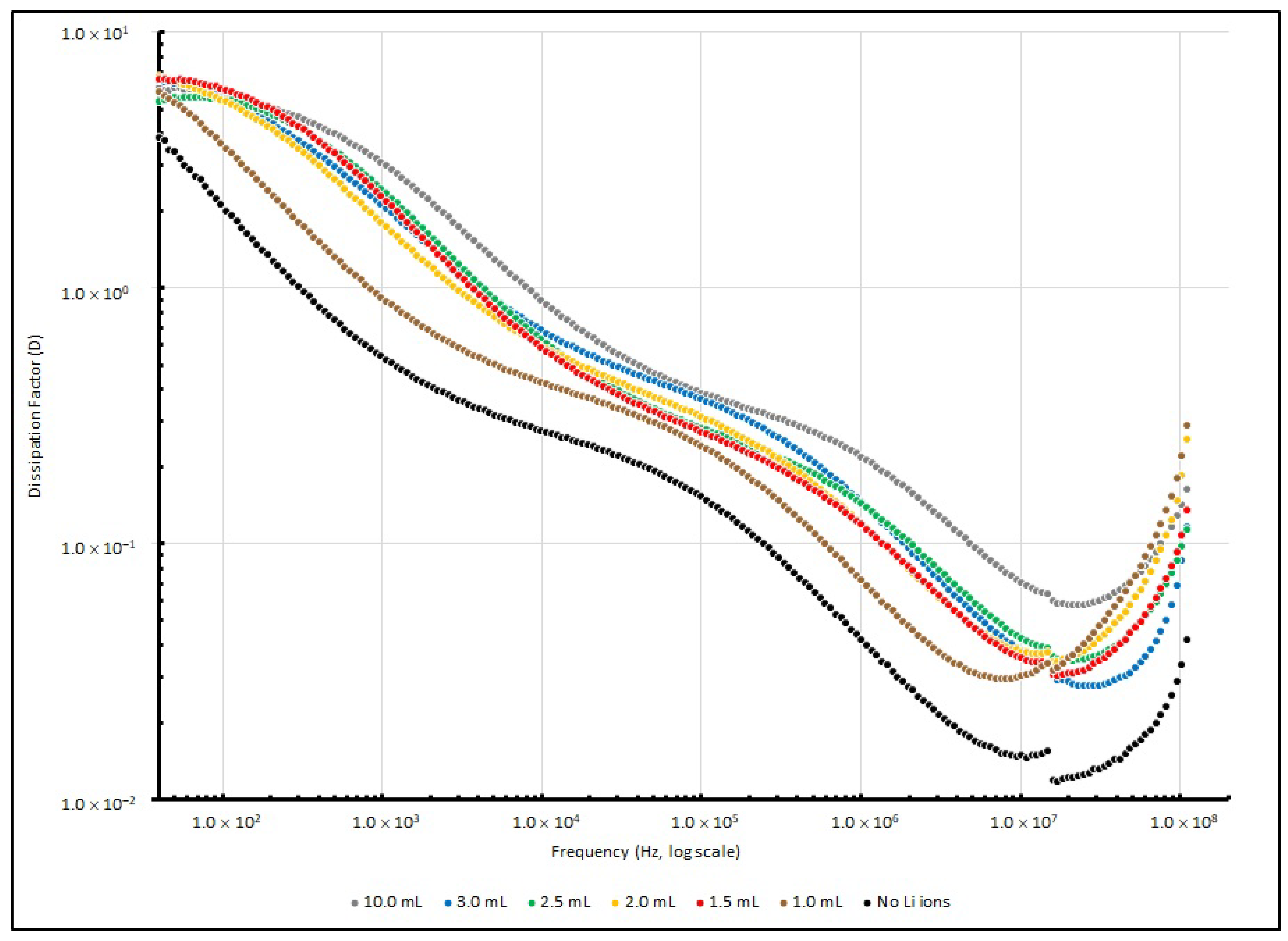
Table 7 summarises the D values of various EDL samples measured at several testing frequencies (40, 1 K, 100 K and 100 MHz), and Figure 8 illustrates these changes. After the testing signal was raised to 10 kHz, the dissipation factor of all of the samples decreased to below 1, and reached the lowest point at around 10 MHz. This implies that the PEO-based Li+-doped samples perform with higher efficiency in a higher frequency range than in a lower frequency range.
Other than Cs and D, the values of X and R were also obtained. The measured R and X of the various EDL samples measured at several testing frequencies (40, 1 K, 100 K and 100 MHz) are summarised in Table 8 and Table 9, respectively. Moreover, 
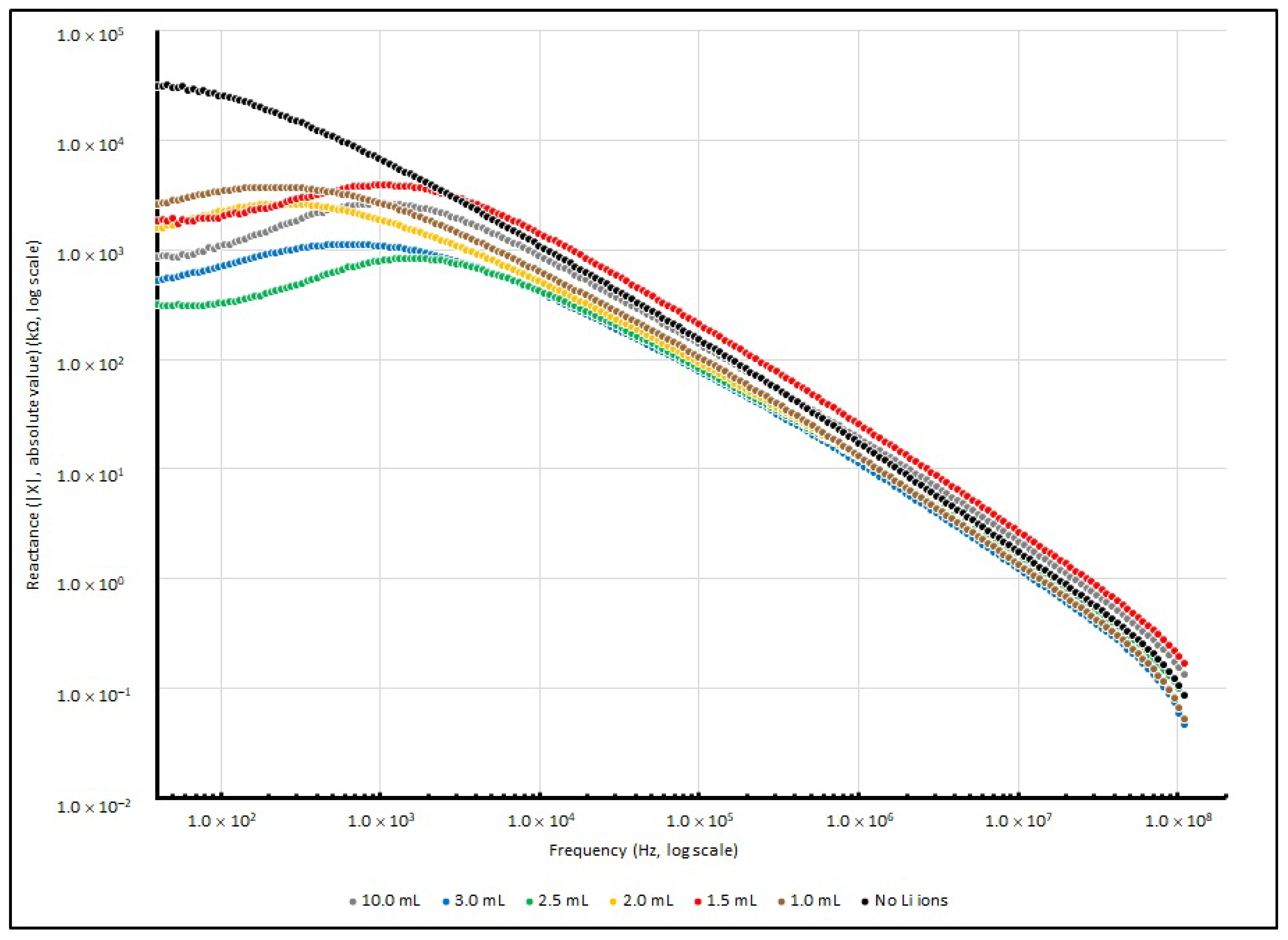
Figure 9 illustrates the changes in series resistance from 40 to 100 MHz. For reactance changes, the absolute reactance (|X|) instead of reactance (X) from 40 to 100 MHz is illustrated in Figure 10, as the negative magnitude is used to show that the measured reactance is dominated by capacitive elements.
Theoretically, the sample measurement of total impedance (Z) should involve a pair of elements: the real and imaginary part, which represent the resistive element (R) and reactive element (X), respectively. For the control sample with no doped Li+, when the testing frequency increases from 40 to 100 MHz, the resistance (R) decreases from 46 MΩ to only a few Ω. In terms of reactance (X), it changes from −31 MΩ to about 110 Ω when the frequency increases from 40 to 100 MHz.
Additionally, for Li+-ion-doped samples, the resistance decreases from a few MΩ to less than 20 Ω when the frequency increases from 40 to 100 MHz. In terms of reactance (X), it slightly increases from a lower frequency range and touches the highest value at about 1 kHz, and at 100 MHz, it decreases to less than 200 Ω. A negative magnitude is measured, which indicates that the capacitive reactance is dominated in the impedance.
In electrochemical impedance spectroscopy, a sinusoidal signal E(ω,t) = Eo sin ωt is injected into the sample during measurement, where Eo is the amplitude of signal and f is the variable frequency (provided that ω is the angular frequency, and hence ω = 2πf). At the same frequencies, the comparable current I(ω,t) is recorded. Hence, the comparable impedance Z(ω,t) with respect to the examined samples can be acquired from Ohm’s law, as follows:
Z ω , t = V ω , t I ω , t
Sinusoidal current recorded from samples at a certain angular frequency ω can appear in the same or opposite phase to the comparable periodic sine wave injected, meaning the current can be written as I(ω,t) = Io sin (ωt − θ), where θ is the phase angle between the potential and current and Io is the current amplitude. In the expression of complex number notation, the AC potential can be rewritten as E(ω,t) = Eo ejωt and the current signal can be expressed as I(ω,t) = Io ej(ωt − θ), where j is the imaginary unit. Through these conversions, Equation (5) can be rewritten as follows:
Z ω , t = E ω , t I ω , t = E o I o e j θ = Z ω e j θ  
where θ is the impedance phase angle and |Z| is the impedance modulus. By using Euler’s formula, Equation (6) can be further rewritten as follows:
Z ω , t = Z ω cos θ + j sin θ = Z ω + j Z ω  
where Z′ = |Z| cosθ and Z″ = |Z| sinθ are the real and imaginary part of the impedance, respectively. Therefore, from Equation (7), the modulus |Z(ω)| and the phase angle of impedance θ(ω) can be obtained by the following:
Z ω = Z 2 ω + Z 2 ω  
θ ω = tan 1 [ Z ω / Z ω ]  
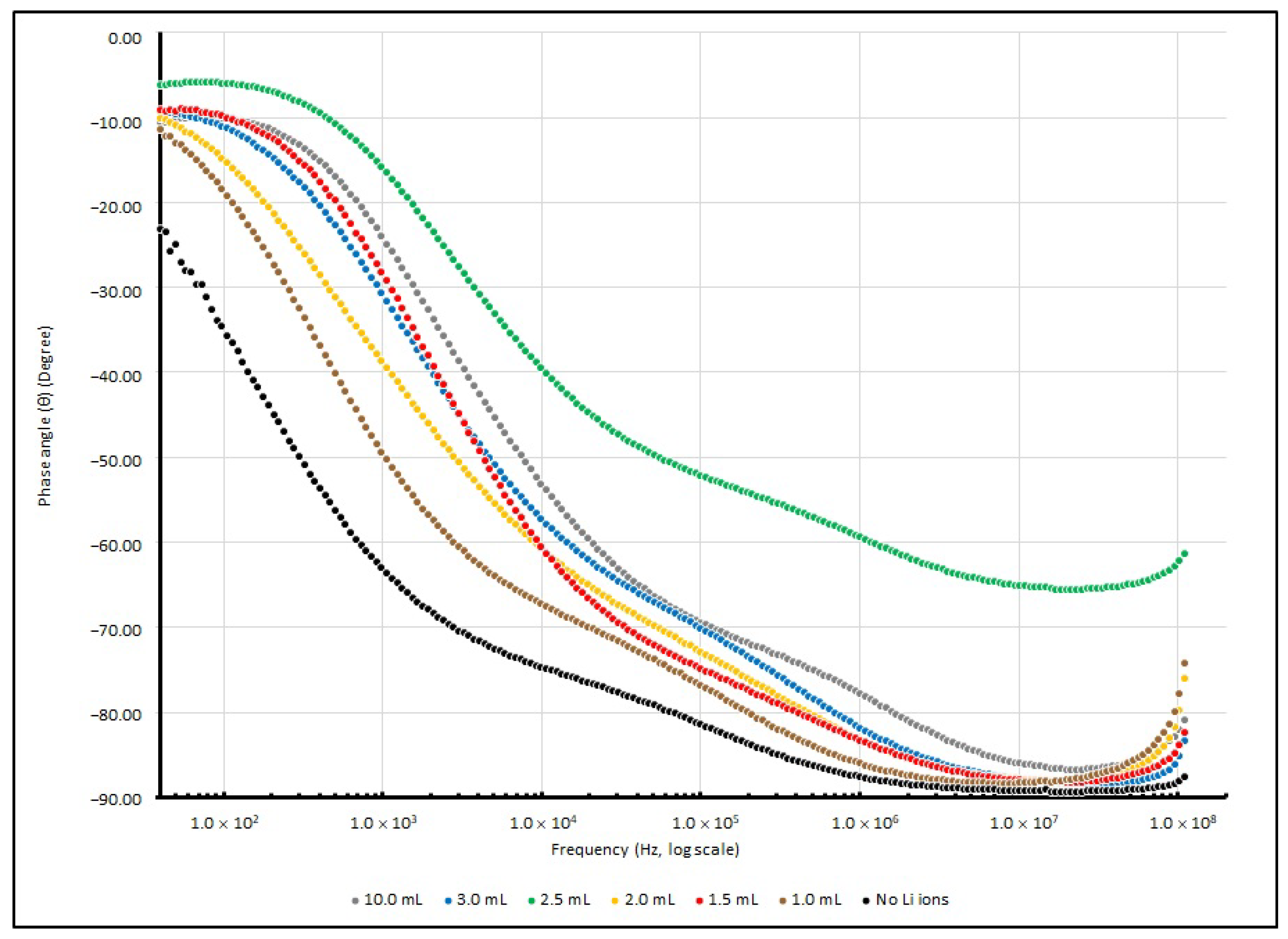
With the relation of Equations (8) and (9), the connection between the resistance and reactance of the EDL system can be derived, and the phase angle (θ) between R and X and |Z| can be found throughout the experiment. Hence, |Z| and θ measured from various Li+-doped EDL samples at several testing frequencies (40, 1 K, 100 K and 100 MHz) are summarised in Table 10 and Table 11. Moreover, their changes in |Z| and θ from 40 to 100 MHz are illustrated in Figure 11 and Figure 12.
The control sample without doped Li+ ions shows the highest magnitude of |Z| and θ at 40 Hz. It seems that the absence of Li+ ions causes poor charge mobility, and the capacitive element in the reactance causes a large phase difference between the resistive and reactive elements. When the testing frequency increases, the magnitude of |Z| and θ drops and responses are similar to other Li+-doped samples.
A dramatic decrease in R, X and |Z| in different lithium-ion-doped samples can be observed; in a low frequency range, these values dropped to 25% or less of the samples without any dopants. This phenomenon indicates that an enrichment in charge mobility in the electrolyte can occur via the existence of lithium ions in the PEO matrix and establishes an enhancement in the charge storage capability. Furthermore, at around 1 kHz, the existence of lithium ions initiates a particular influence on reactance.

3.4. Cyclic Voltammetry of PEO-Based EDL Capacitors with Various LiClO4 Concentrations

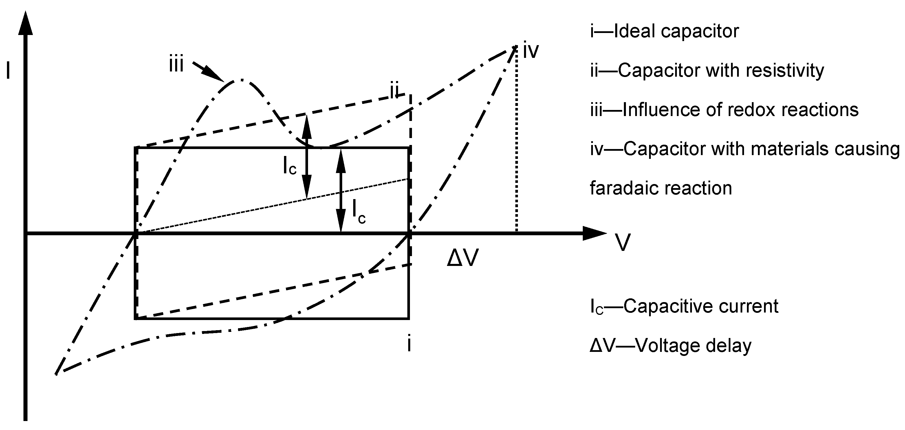
Theoretically, the charging–discharging behaviour of an ideal double-layer capacitor can be illustrated via voltammetry characteristics in a rectangular form (Figure 13). In the diagram, when the potential direction was reversed, the current flow was reversed immediately. In the system, electrostatic potential can be seen as part of the charge storage mechanism, and generally, the potential and current are mostly independent of each other. If materials with pseudocapacitance properties are used as electrodes, the form of the voltammetry curve changes, and redox peaks due to pseudofaradaic reactions are noticed in some cases. In contrast, the electrode potential dominated charges accumulated in the capacitor in this experiment. As the charging of pseudocapacitance involves kinetically slow processes, during the reverse in potential, a delay in potential change occurs [37]. In the following Table 12, the maximum current densities of different scan rates are tabulated.
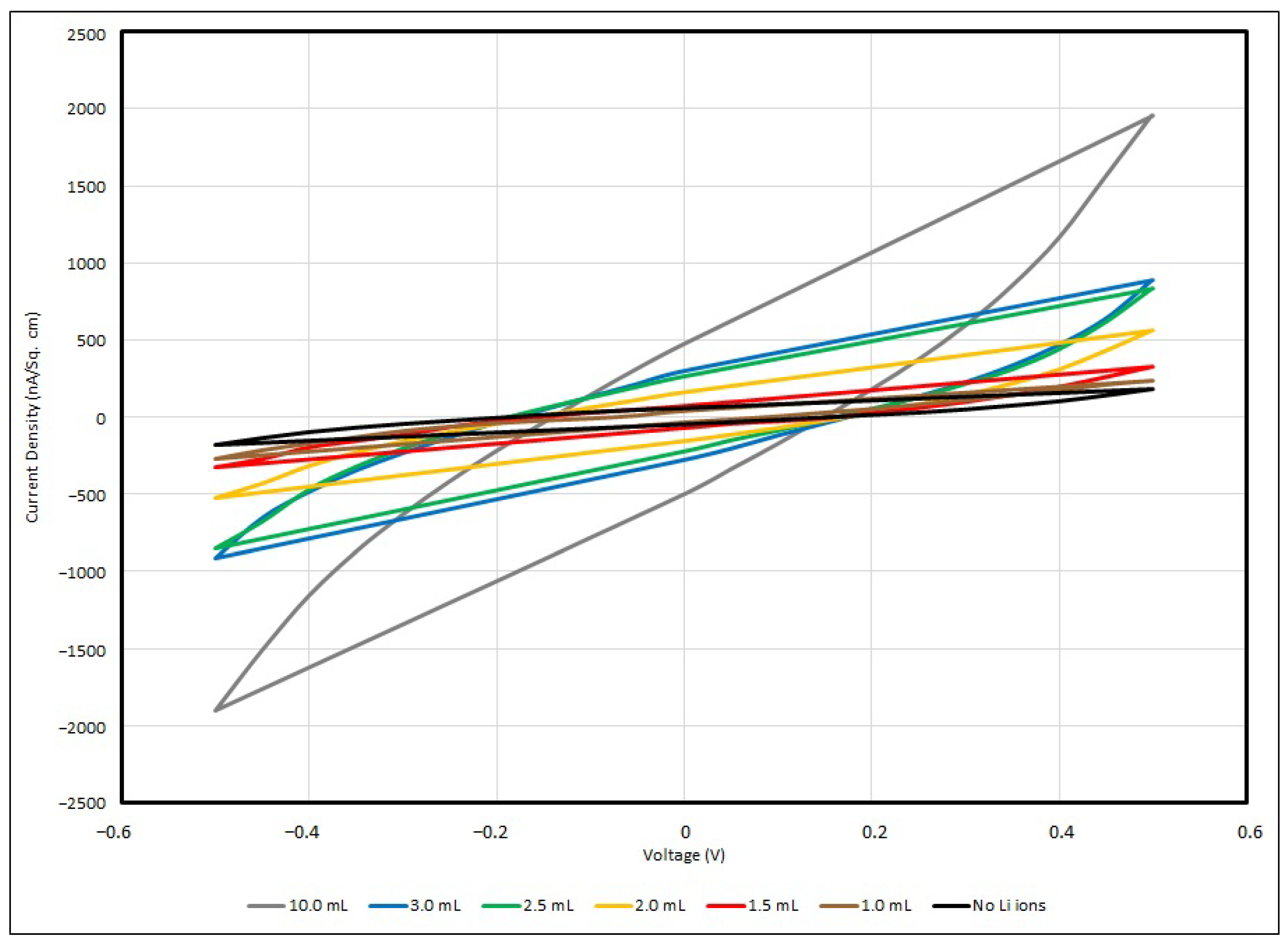
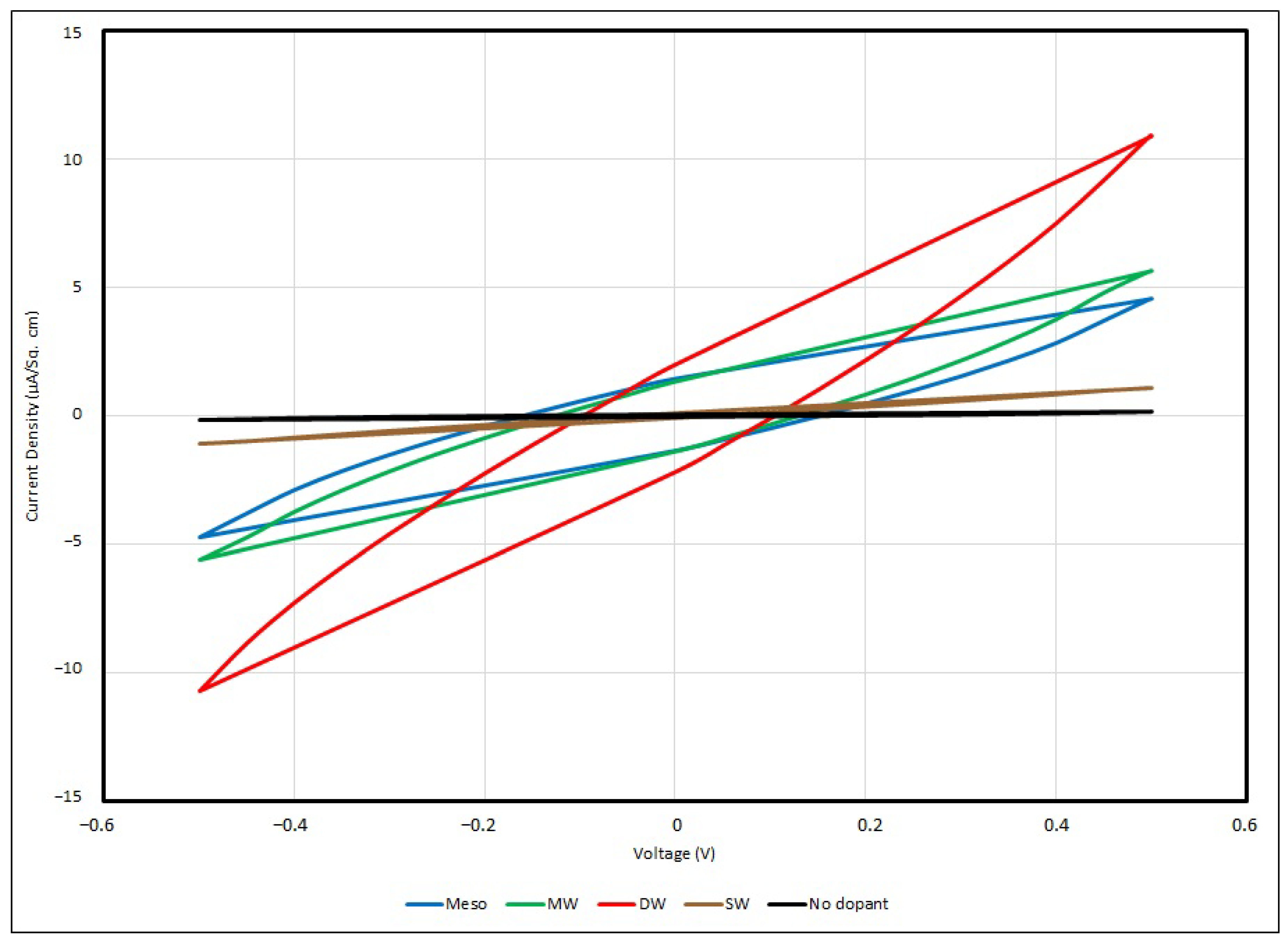
In general, all samples of the PEO-based supercapacitor give voltammograms in an olive shape, and the maximum current densities can be found at 0.5 V and −0.5 V, with respect to the positive or negative potential. In the experiment, a faster scan rate gives a higher value of current density, and vice versa, so that a slower scan rate gives a lower value, and for all samples, no matter how the scan rate is changed, the cyclic voltage–current density responses are quite similar. This can be described in terms of the time taken to record the scan and the size of the diffusion layer. Since the applied potential gradually increases, the current follows the potential to rise correspondingly from its initial value at the negative side, and then shifts to the positive side. Hence, a greater number of reactants in the electrolyte are transformed, and the diffusion layer sufficiently grows above the Cu-plated polyester fabrics.
In practice, the efficiency of charges moving from one active site to another in the PEO matrix is ruled by the diffusion layer formation. The potential applied to the supercapacitor samples is longer when a slower scan rate is used, and therefore, in contrast to using a faster scan rate measurement, the diffusion layer can develop far away from the metallised fabric surface towards the electrolyte, resulting in the potential occurrence of an ineffective charge transfer. In addition, a faster scan rate allows for a relatively larger current flux to pass through the metallised fabric surface than a slower one. As the current density applied to the testing sample during the measurement is proportionate to the current flux towards the metallised surface, at a faster scan rate, a larger magnitude of current density is triggered by a higher flux. This is a fast response process and this electron transfer reaction is usually regarded as being reversible.
From the empirical results, the maximum current density of the control sample is about 177 nA/cm2 under a scanning rate of 100 mV/s with applied voltage of ± 0.5 V. Once the Li+ ions have been added into the PEO matrix, the charge mobility becomes enhanced, and when the Li+ ion concentration has been increased from 0.001 to 0.01, the maximum current density dramatically increases from 243 nA/cm2 to 1844 nA/cm2. Lithium ions can migrate among nearby active sites in the PEO backbone and branches when sufficient Li+ ions are provided to the PEO matrix; hence, the current density flowing through the EDL supercapacitor sample and the charge storage capability are enhanced. Taken from Lim et al., around 0.1 mA/cm2 was obtained if the Li+ ion concentration was raised to 5 wt% LiClO4-PEO, with WO3-coated ITO as the electrode [14]. The cyclic voltammogram below (Figure 14) illustrates the responses of voltage–current in different PEO:Li+-based EDL capacitors with various salt concentrations under a scanning rate of 100 mV/s.

3.5. Frequency Responses of PEO-Based EDL Capacitors with Various Types of Nanocarbons

Other than lithium salt in a previous experiment, PEO-based EDL capacitors were doped with various types of nanocarbons and their electrical properties were examined. These nanocarbons have a similar density to (i) mesoporous nanocarbons (Meso); (ii) multi-walled carbon nanotubes (MW); (iii) double-walled carbon nanotubes (DW) and (iv) single-walled carbon nanotubes (SW). An impedance analyser ranging from 40 to 110 MHz was used to investigate the electrical properties of PEO-based samples, parameters involving series capacitance (Cs), the dissipation factor (D), series resistance (R), series reactance (X), absolute impedance (|Z|) and the phase difference between the resistance and reactance (θ).
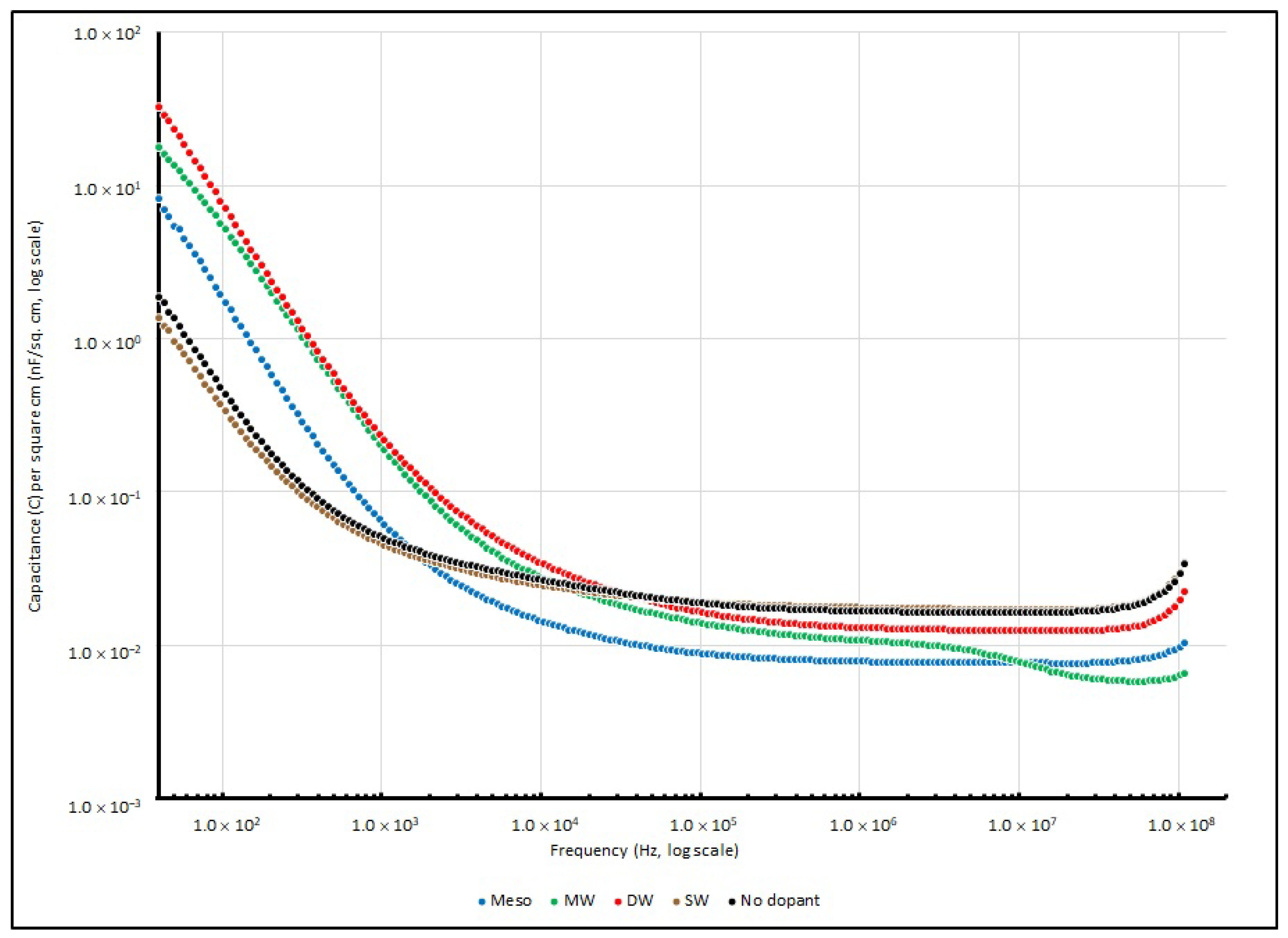
PEO-based supercapacitor samples doped with different types of nanocarbons were connected to the impedance analyser, their Cs were measured and their corresponding specific capacitance values were determined. Table 13 summarises their specific capacitance at several testing frequencies (40, 1 K, 100 K and 100 MHz), and their change in specific capacitance is illustrated in Figure 15.
Mostly, in the range of frequencies from 40 to 100 MHz, similar trends can be observed in all four different types of nanocarbon samples. On the other hand, when the frequency is below 1 kHz, all PEO:nanocarbon supercapacitors show higher values of specific capacitance than the other frequency ranges.
Among all four nanocarbon samples, DW shows the best performance and gives a specific capacitance of 32.798 nF/cm2 at 40 Hz, followed by MW, Meso and SW with values of 17.806, 8.238 and 1.353 nF/cm2, respectively. However, the specific capacitances of all samples drastically drop when the testing signal increases to 10 kHz, and they reach the minimum throughout the high frequency range at 100 MHz.
Table 14 summarises the dissipation factors (D) of all of the PEO:nanocarbon EDL samples recorded at several testing frequencies (40, 1 K, 100 K and 100 MHz), and in Figure 16, their dissipation factor changes are illustrated.
Similarly to the Li+-doped samples, after the testing frequency was raised to 6 kHz, the dissipation factor of all samples decreased to below 1, and the nanocarbon-doped samples reached the lowest point in the range of 1 MHz to 10 MHz. However, after reaching 10 MHz, their efficiencies slightly bounced back to near 1. The empirical results showed that the working bandwidth of the nanocarbon-doped samples was narrower than that of the Li+-doped samples, and more frequency-dependent in this electrochemical system.
Charge accumulation in this EDL system increases greatly when various nanocarbons are added into the PEO matrix, as these dopants can increase the total surface area in the matrix, and free charges in this system can be easily captured. From the empirical results, the specific capacitance of DW is the highest among the four nanocarbons. Physically, DW consists of two SWs with inner and outer nanotubes, which is a simple form of MW. For nanotube walls, their electronic configurations can either be metallic (M) or semiconducting (S). According to these phenomena, there are four possible combinations that can be obtained in DW; they are M-M, M-S, S-M and S-S (outer nanotube–inner nanotube). These four combinations improve the capability of charge trapping in the system by advancing the electrical conductivity. Researchers have suggested that DW with an M-M configuration can perform like SW in a metallic configuration, where the electrical properties of the material are as good as the metal, and can also perform on an advanced surface for charge trapping in the EDL system [38,39,40]. Other than Cs and D, the value of X and R were also obtained. The measured R and X of various EDL samples measured at several testing frequencies (40, 1K, 100K and 100M Hz) are summarised in Table 15 and 
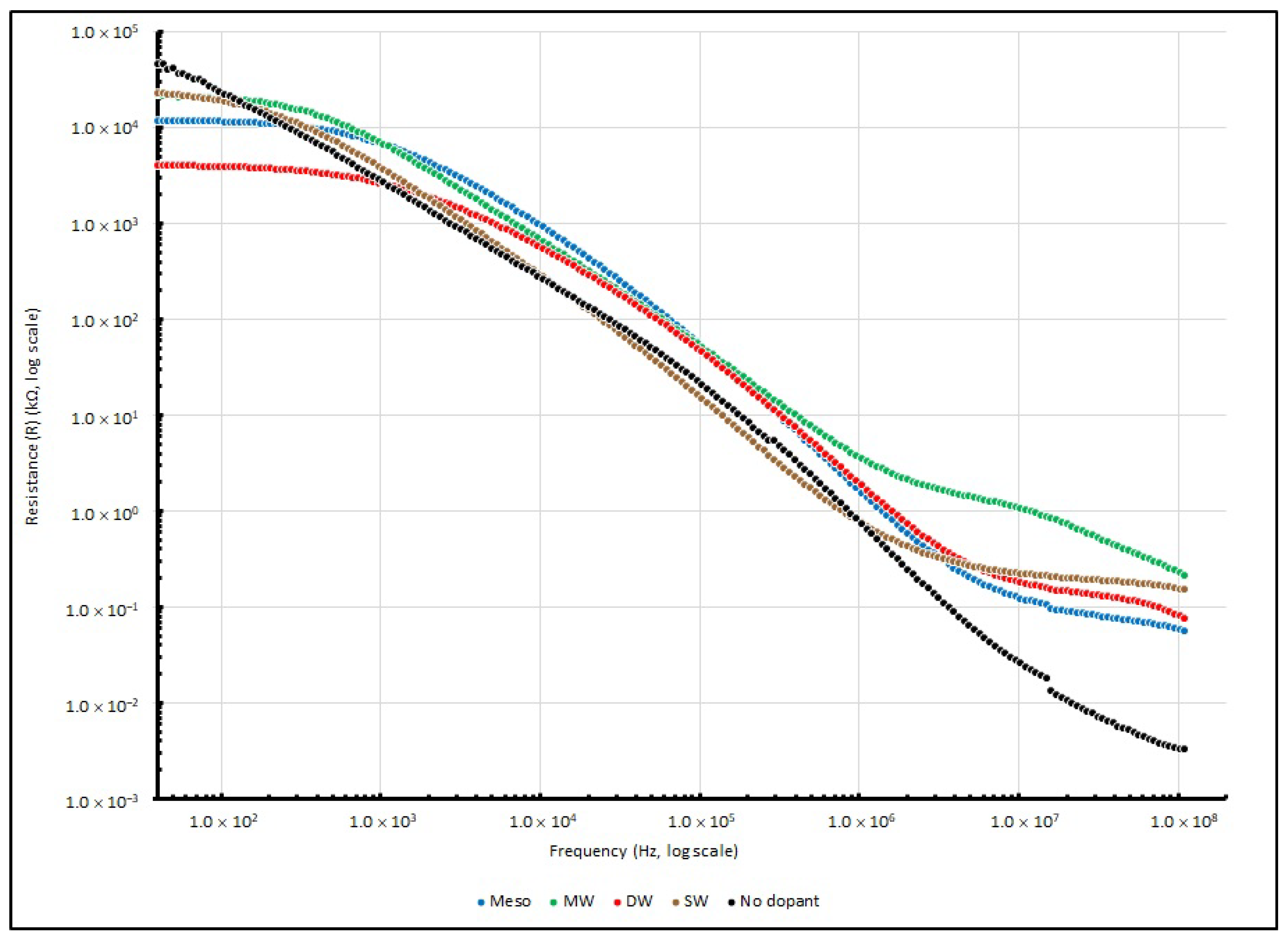
Table 16, respectively. Moreover, the changes in series resistance from 40 to 100 MHz are illustrated in Figure 17. For the change in reactance, the absolute reactance (|X|) instead of reactance (X) from 40 to 100 MHz is illustrated in Figure 18, and the negative magnitude is used to show that the measured reactance is dominated by capacitive elements.
Theoretically, the sample measurement of total impedance (Z) should involve a pair of elements: the real and imaginary part, which represent the resistive element (R) and reactive element (X), respectively. In the experiment, when the testing frequency increases and reaches 100 MHz, the resistance of all of the PEO:nanocarbon samples decreases from MΩ to a few tens of Ω. Among the four samples, DW shows the lowest R, which is one order of magnitude less than the other samples. Additionally, when the testing frequency rises, the reactance of all of the PEO:nanocarbon samples decreases from kΩ to tens to hundreds of Ω at 100 MHz. DW shows the lowest X, which is one order of magnitude less than the other samples, as the negative magnitude of X is used to show that the measured reactance is dominated by the capacitive elements.
|Z| and θ data from the experiment taken from different nanocarbon-doped EDL samples at several testing frequencies (40, 1 K, 100 K and 100 MHz) are summarised in Table 17 and Table 18, respectively. Moreover, their changes in |Z| and θ from 40 to 100 MHz are illustrated in Figure 19 and Figure 20, respectively.
The magnitude of |Z| for all PEO:nanocarbon samples is more or less the same as the series resistances at 100 Hz or below; it seems that the reactance of all samples exhibits a negligible effect on |Z|. On the other hand, a negative value of θ in all readings shows that capacitive elements dominate the reactance. These phenomena show that resistive elements are largely governed by the frequency responses of an electrochemical system. The reactive element begins to influence |Z| after the testing frequency increases to 1 kHz, and beyond 1 kHz, the phase angle increases as |Z| is influenced by R and X at the same time. When the frequency reaches 100 kHz, the phase angle of all of the nanocarbon-doped samples increases rapidly to more than −75°; this shows that capacitive reactance is the major component affecting the magnitude of |Z|. However, the reactance response of SW becomes different after the frequency is raised beyond 100 kHz. The phase angle decreases along with the increase in frequency, and reaches −30.47° at 100 MHz.
A comparison of all four PEO:nanocarbon samples shows that the resistance, reactance and impedance values of DW are much smaller than those of other PEO:nanocarbon samples. The empirical results suggest that the charge mobility in the PEO electrolyte can be enhanced if DW is doped into the PEO matrix, by providing a more advanced environment than the other three types of nanocarbons, and further improve the charge storage capability. Moreover, for the testing frequency at 1 kHz, the presence of nanocarbons can trigger some effects on reactance.

3.6. Cyclic Voltammetry of PEO-Based EDL Capacitors with Various Types of Nanocarbons

Generally, all PEO:nanocarbon supercapacitors give voltammograms in an olive shape, and the maximum current densities can be found at 0.5 V and −0.5 V with respect to the positive or negative potential. In the experiment, a faster scan rate gives a higher value of current density, and vice versa, whereby a slower scan rate gives a lower value, and for all samples, no matter how the scan rate is changed, the cyclic voltage–current density responses are of a similar shape. In Table 19, the maximum current densities of different scanning rates are summarised, and the cyclic voltammogram (Figure 21) illustrates the responses of voltage–current in different PEO:nanocarbon EDL capacitors under a scanning rate of 100 mV/s.
The DW-doped PEO-based EDL capacitor shows a significantly higher value of current density than the other dopants; it gives 10.51 μA/cm2 under a scanning rate of 100 mV/s with applied voltage of ±0.5 V, which is nearly two times that compared to the values from MW and mesoporous nanocarbons, and nearly ten times that of the samples doped with SW. From the results, it is obvious that the electrical properties exhibited by DW are better than the samples doped with other nanocarbons. As reported by Borges et al., the current density of their sample with a similar structure, using copolymer polyethylene-b-poly(ethylene oxide) as the polymer electrolyte and DW as a nanocomposite, would give a value around 5 μA/cm2 under a scanning rate of 5 mV/s, with applied voltage of ±0.5 V [16].

4. Conclusions

In this study, LiClO4 and various types of nanocarbons were doped into active layers of PEO-based EDL capacitors, and their electrical properties were examined using an impedance analyser and cyclic voltammetry. For the experiment on LiClO4, different concentrations of LiClO4 were doped into the active layer of the supercapacitor. At 40 Hz, the sample prepared under the ratio of 100:1 of PEO:Li+ gives a specific capacitance of 33.56 nF/cm2 and a maximum current density of 1844 nA/cm2 under a scanning rate of 100 mV/s with applied voltage of ±0.5 V, which are 18 times and 10 times more than those of the sample without LiClO4 doping. It is observed that a higher LiClO4 concentration can provide better charging capability. For the experiment on different types of nanocarbons, nanocarbons with four different structures, including mesoporous carbon nanopowders (Meso) and multi-walled (MW), double-walled (DW) and single-walled (SW) carbon nanotubes, were doped into the active layer of the supercapacitor. At 40 Hz, the sample doped with the double-walled carbon nanotube gives a specific capacitance of 32.798 nF/cm2 and a maximum current density of 10.51 μA/cm2 under a scanning rate of 100 mV/s with applied voltage of ±0.5 V, which are 17 times and 60 times more than those of the sample without LiClO4 doping. It is suggested that compared to other types of nanocarbons, samples doped with double-walled carbon nanotubes can provide better electrical properties. The empirical results demonstrate the electrical properties of a solvent-free PEO-based EDL supercapacitor doped with LiClO4 and nanocarbons on flexible conducting fabrics. This system can provide some basic information to help other researchers to design devices like wearable supercapacitors, taking advantage of the flexibility and strength of metallised polyester fabrics, and hence can further improve devices in terms of different electrical and mechanical properties, and also geometrical configurations.

Author Contributions

Conceptualization, C.-Y.H. and C.-W.K.; methodology, C.-Y.H., C.-W.K. and K.-H.C.; validation, C.-Y.H. and C.-W.K.; formal analysis, C.-Y.H. and C.-W.K.; investigation, C.-Y.H. and C.-W.K.; resources, C.-W.K.; data curation, C.-Y.H., C.-W.K. and K.-H.C.; writing—original draft preparation, C.-Y.H.; writing—review and editing, C.-W.K.; visualization, C.-Y.H. and C.-W.K.; supervision, C.-W.K.; project administration, C.-W.K.; funding acquisition, C.-W.K. All authors have read and agreed to the published version of the manuscript.

Funding

This research was funded by The Hong Kong Polytechnic University, grant number ZDCC.

Institutional Review Board Statement

Not applicable.

Informed Consent Statement

Not applicable.

Data Availability Statement

Not applicable.

Conflicts of Interest

The authors declare no conflict of interest.

References

  1. Liu, C.G.; Yu, Z.N.; Neff, D.; Zhamu, A.; Jang, B.Z. Graphene-based supercapacitor with an ultrahigh energy density. Nano Lett. 2010, 10, 4863–4868. [Google Scholar] [CrossRef]
  2. Balducci, A.; Dugas, R.; Taberna, P.; Simon, P.; Plee, D.; Mastragostino, M.; Passerini, S. High temperature carbon-carbon supercapacitor using ionic liquid as electrolyte. J. Power Sources 2007, 165, 922–927. [Google Scholar] [CrossRef] [Green Version]
  3. Mastragostino, M.; Arbizzani, C.; Soavi, F. Polymer-based supercapacitors. J. Power Sources 2001, 97–98, 812–815. [Google Scholar] [CrossRef]
  4. Pandolfo, A.G.; Hollenkamp, A.F. Carbon properties and their role in supercapacitors. J. Power Sources 2006, 157, 11–27. [Google Scholar] [CrossRef]
  5. Snook, G.A.; Kao, P.; Best, A.S. Conducting-polymer-based supercapacitor devices and electrodes. J. Power Sources 2011, 196, 1–12. [Google Scholar] [CrossRef]
  6. Zhang, L.L.; Zhao, X.S. Carbon-based materials as supercapacitor electrodes. Chem. Soc. Rev. 2009, 38, 2520–2531. [Google Scholar] [CrossRef]
  7. Frackowiak, E.; Khomenko, V.; Jurewicz, K.; Lota, K.; Beguin, F. Supercapacitors based on conducting polymers/nanotubes composites. J. Power Sources 2006, 153, 413–418. [Google Scholar] [CrossRef]
  8. Lee, S.W.; Kim, B.S.; Chen, S.; Yang, S.H.; Hammond, P.T. Layer-by-layer assembly of all carbon nanotube ultrathin films for electrochemical applications. J. Am. Chem. 2009, 131, 671–679. [Google Scholar] [CrossRef]
  9. Jost, K.; Perez, C.R.; McDonough, J.K.; Presser, V.; Heon, M.; Dion, G.; Gogotsi, Y. Carbon coated textiles for flexible energy storage. Energy Environ. Sci. 2011, 4, 5060–5067. [Google Scholar] [CrossRef]
  10. Huang, Y.; Hu, H.; Huang, Y.; Zhu, M.; Meng, W.; Liu, C.; Pei, Z.; Hao, C.; Wang, Z.; Zhi, C. From industrially weavable and knittable highly conductive yarns to large wearable energy storage textiles. ACS Nano 2015, 9, 4766–4775. [Google Scholar] [CrossRef]
  11. Dong, L.; Xu, C.; Li, Y.; Wu, C.; Jiang, B.; Yang, Q.; Zhou, E.; Kang, F.; Yang, Q. Simultaneous production of high-performance flexible textile electrodes and fiber electrodes for wearable energy storage. Adv. Mater. 2016, 28, 1675–1681. [Google Scholar] [CrossRef]
  12. Gan, X.P.; Wu, Y.T.; Liu, L.; Shen, B.; Hu, W.B. Electroless copper plating on PET fabrics using hypophosphite as reducing agent. Surf. Coat. 2007, 201, 7018–7023. [Google Scholar] [CrossRef]
  13. Liu, X.; Osaka, T. Properties of electric double-layer capacitors with various polymer gel electrolytes. J. Electrochem. Soc. 1997, 144, 3066–3071. [Google Scholar] [CrossRef]
  14. Lim, B.H.; Kim, J.M.; Nguyen, V.; Kim, H.; Park, C.W.; Lee, J.K.; Lee, C.; Yoo, J.; Min, B.K.; Kim, S.K. Functionalized methyl cellulose/LiClO4 composite as an environmentally friendly quasi-solid polymer electrolyte for solid-state electrochromic devices and cellulose-based supercapacitors. Mater. Today Energy 2023, 33, 101263. [Google Scholar] [CrossRef]
  15. Hashmi, S.A.; Latham, R.J.; Linford, R.G.; Schlindwein, W.S. Studies on all solid state electric double layer capacitors using proton and lithium ion conducting polymer electrolytes. J. Chem. Soc. Faraday Trans. 1997, 93, 4177–4182. [Google Scholar] [CrossRef]
  16. Borges, R.S.; Miquita, D.R.; Silva, G.G. Electrochemical study of double-walled carbon nanotube electrode/block polyether-lithium bis(trifluorosulphonyl)imide salt polymer electrolyte interface. Electrochim. Acta 2011, 56, 4650–4656. [Google Scholar] [CrossRef]
  17. Lust, E.; Nurk, G.; Jänes, A.; Arulepp, M.; Nigu, P.; Möller, P.; Kallip, S.; Sammelselg, V. Electrochemical properties of nanoporous carbon electrodes in various nonaqueous electrolytes. J. Solid State Electrochem. 2003, 7, 91–105. [Google Scholar] [CrossRef]
  18. Gan, X.P.; Wu, Y.T.; Liu, L.; Shen, B.; Hu, W.B. Electroless plating of Cu-Ni-P alloy on PET fabrics and effect of plating parameters on the properties of conductive fabrics. J. Alloys Compd. 2008, 455, 308–313. [Google Scholar] [CrossRef]
  19. Han, E.G.; Kim, E.A.; Oh, K.W. Electromagnetic interference shielding effectiveness of electroless Cu-plated PET fabrics. Synth. Met. 2001, 123, 469–476. [Google Scholar] [CrossRef]
  20. Gasana, E.; Westbroek, P.; Hakuzimana, J.; De Clerck, K.; Priniotakis, G.; Kiekens, P.; Tseles, D. Electroconductive textile structures through electroless deposition of polypyrrole and copper at polyaramide surfaces. Surf. Coat. 2006, 201, 3547–3551. [Google Scholar] [CrossRef]
  21. Park, N.W.; Kim, I.W.; Kim, J.Y. Copper Metallization of poly(ethylene terephthalate) Fabrics via Intermediate Polyaniline Layers. Fibers Polym. 2009, 10, 310–314. [Google Scholar] [CrossRef]
  22. Shoji, E.; Takagi, S.; Araie, H. Novel conducting fabric polymer composites as stretchable electrodes: One-step fabrication of chemical actuators. Polym. Adv. Technol. 2009, 20, 423–426. [Google Scholar] [CrossRef]
  23. Lu, Y.X.; Xue, L.L.; Li, F. Silver nanoparticle catalyst for electroless Ni deposition and the promotion of its adsorption onto PET substrate. Surf. Coat. 2010, 205, 519–524. [Google Scholar] [CrossRef]
  24. Kofod, G.; Stoyanov, H.; Gerhard, R. Multilayer coaxial fibre dielectric elastomers for actuation and sensing. Appl. Phys. A 2011, 102, 577–581. [Google Scholar] [CrossRef]
  25. Zheng, Z.R.; Gu, Z.Y.; Huo, R.T.; Ye, Y.H. Superhydrophobicity of polyvinylidene fluoride membrane fabricated by chemical vapour deposition from solution. Appl. Surf. Sci. 2009, 255, 7263–7267. [Google Scholar] [CrossRef]
  26. Das, R.N.; Rosser, S.G.; Papathomas, K.I.; Poliks, M.D.; Lauffer, J.M.; Markovich, V.R. Resin coated copper capacitive (RC3) nanocomposites for multilayer embedded capacitors. In Proceedings of the 2008 58th Electronic Components and Technology Conference, Lake Buena Vista, FL, USA, 27–30 May 2008; pp. 729–735. [Google Scholar]
  27. Das, R.N.; Rosser, S.G.; Papathomas, K.I.; Antesberger, T.; Markovich, V.R. Resin coated copper capacitive (RC3) nanocomposites for multilayer embedded capacitors: Towards system in a package (SiP). Circuit World 2009, 35, 31–39. [Google Scholar] [CrossRef]
  28. Sun, Y.Y.; Li, X.; Gandhi, J.; Luo, S.J.; Jiang, T. Adhesion improvement for polymer dielectric to electrolytic-plated copper. In Proceedings of the 2010 Proceedings 60th Electronic Components and Technology Conference (ECTC), Las Vegas, NV, USA, 1–4 June 2010; pp. 1106–1111. [Google Scholar]
  29. Armand, M. Polymers with ionic conductivity. Adv Mater. 1990, 2, 278–286. [Google Scholar] [CrossRef]
  30. Xi, J.; Qiu, X.; Zhu, W.; Tang, X. Enhanced electrochemical properties of poly(ethylene oxide)-based composite polymer electrolyte with ordered mesoporous materials for lithium polymer battery. Microporous Mesoporous Mater. 2006, 88, 1–7. [Google Scholar] [CrossRef]
  31. Gadjourova, Z.; Andreev, Y.G.; Tunstall, D.P.; Bruce, P.G. Ionic conductivity in crystalline polymer electrolytes. Nature 2001, 412, 520–523. [Google Scholar] [CrossRef]
  32. Edman, L.; Ferry, A.; Doeff, M.M. Slow recrystallization in the polymer electrolyte system poly(ethylene oxide)n–LiN(CF3SO2)2. J. Mater. Res. 2000, 15, 1950–1954. [Google Scholar] [CrossRef]
  33. Strawhecker, K.E.; Manias, E. Crystallization behavior of poly(ethylene oxide) in the presence of Na+ montmorillonite fillers. Chem. Mater. 2003, 15, 844–849. [Google Scholar] [CrossRef]
  34. Bac, A.; Ciosek, M.; Bukat, M.; Siekierski, M.; Wieczorek, W. The effect of salt concentration on the PEO-LiClO4-lithium electrode interfacial resistivity. J. Power Sources 2006, 159, 438–442. [Google Scholar] [CrossRef]
  35. Hadjichristov, G.B.; Ivanov, T.E.; Marinov, Y.G.; Koduru, H.K.; Scaramuzza, N. PEO-PVP-NaIO4 ion-conducting polymer electrolyte: Inspection for ionic space charge polarization and charge trapping. Phys. Status Solidi A 2019, 216, 1800739. [Google Scholar] [CrossRef]
  36. Meyer, W.H. Polymer Electrolytes for Lithium-Ion Batteries. Adv. Mater. 1998, 10, 439–448. [Google Scholar] [CrossRef]
  37. Frackowiak, E.; Béguin, F. Carbon materials for the electrochemical storage of energy in capacitors. Carbon 2001, 39, 937–950. [Google Scholar] [CrossRef]
  38. Moradian, R.; Azadi, S.; Refii-tabar, H. When double-wall carbon nanotubes can become metallic or semiconducting. J. Condens. Matter Phys. 2007, 19, 176209. [Google Scholar] [CrossRef]
  39. Villalpando-Paez, F.; Son, H.; Nezich, D.; Hsieh, Y.P.; Kong, J.; Kim, Y.A.; Shimamoto, D.; Muramatsu, H.; Hayashi, T.; Endo, M.; et al. Raman spectroscopy study of isolated double-walled carbon nanotubes with different metallic and semiconducting configurations. Nano Lett. 2008, 8, 3879–3886. [Google Scholar] [CrossRef]
  40. Shen, C.; Brozena, A.H.; Wang, Y.H. Double-walled carbon nanotubes: Challenges and opportunities. Nanoscale 2011, 3, 503–518. [Google Scholar] [CrossRef]
Figure 1. An illustration summarising the surface activation process.
Coatings 13 01373 g001
Figure 2. Illustration showing various PEO:Li+ and PEO:nanocarbon electrolytic material solutions casted on Cu-plated polyester substrates.
Coatings 13 01373 g002
Figure 3. Illustration showing the PEO-based EDL capacitor structure.
Coatings 13 01373 g003
Figure 4. SEM image of (a) the untreated polyester fabric (with 50×); (b) the Pd-coated polyester fabric (with 500×); (c) the Ni-coated polyester fabric (with 500×); and (d) the Cu-coated polyester fabric (with 500×).
Coatings 13 01373 g004aCoatings 13 01373 g004b
Figure 5. SEM image of polyester fabric casted with pure PEO (with 500×).
Coatings 13 01373 g005
Figure 6. Specific capacitances of PEO-based EDL capacitors with various LiClO4 concentrations at different frequencies.
Coatings 13 01373 g006
Figure 7. Illustration showing how the diffusion of Li+ ions is assisted by segmental motion in the PEO matrix.
Coatings 13 01373 g007
Figure 8. Dissipation factors (D) of PEO-based EDL capacitors with various LiClO4 concentrations at different frequencies.
Coatings 13 01373 g008
Figure 9. Resistances (R) of PEO-based EDL capacitors with various LiClO4 concentrations at different frequencies.
Coatings 13 01373 g009
Figure 10. Absolute reactance (|X|) of PEO-based EDL capacitors with various LiClO4 concentrations at different frequencies.
Coatings 13 01373 g010
Figure 11. Absolute impedances (|Z|) of PEO-based EDL capacitors with various LiClO4 concentrations at different frequencies.
Coatings 13 01373 g011
Figure 12. Phase angles (θ) of PEO-based EDL capacitors with various LiClO4 concentrations at different frequencies.
Coatings 13 01373 g012
Figure 13. Conventional cyclic voltammetry of electrochemical capacitors.
Coatings 13 01373 g013
Figure 14. Cyclic voltammograms of PEO-based EDL capacitors with various LiClO4 concentrations under a scanning rate of 100 mV/s.
Coatings 13 01373 g014
Figure 15. Specific capacitances of PEO-based EDL capacitors with various types of nanocarbons at different frequencies.
Coatings 13 01373 g015
Figure 16. Dissipation factors (D) of PEO-based EDL capacitors with various types of nanocarbons at different frequencies.
Coatings 13 01373 g016
Figure 17. Resistance (R) of PEO-based EDL capacitors with various types of nanocarbons at different frequencies.
Coatings 13 01373 g017
Figure 18. Reactance (X) of PEO-based EDL capacitors with various types of nanocarbons at different frequencies.
Coatings 13 01373 g018
Figure 19. Absolute impedances (|Z|) of PEO-based EDL capacitors with various types of nanocarbons at different frequencies.
Coatings 13 01373 g019
Figure 20. Phase angles (θ) of PEO-based EDL capacitors with various types of nanocarbons at different frequencies.
Coatings 13 01373 g020
Figure 21. Cyclic voltammograms of PEO-based EDL capacitors with various types of nanocarbons under a scanning rate of 100 mV/s.
Coatings 13 01373 g021
Table 1. Recent research works about polymeric EDL supercapacitors doped with nanocarbons or lithium salts.
Research
Groups
Electrode
Materials
Electrolytes
Used
Dopants
Applied
Liu et al. [13]HDCPEO/PMMA/PAN mixed with EC and PCLiClO4
Lim et al. [14]WO3 on ITO glassLiClO4-LiMC, LiClO4-PEO,
LiClO4-LiSMC
LiClO4
Hashmi et al. [15](1) High-density graphite sheets
(2) Activated carbon fabrics
PVA-H3PO4,
(PEO)9-LiCF3SO3
LiCF3SO3
Jost et al. [9]Various types of activated carbon impregnation on polyester microfibre and cotton lawnNa2SO4-Li2SO4CXV, YP17,
carbon onions
Borges et al. [16]DWCNT-COOH/PE-b-PEO-LiTFSIPE-b-PEO-LiTFSIDWCNT-COOH
Lust et al. [17]Nanoporous carbon on Al foilLiClO4, LiBF4, Et4NBF4, Et3MeNBF4, EtMe3NBF4Nanoporous
carbon
Table 2. PEO and LiClO4 ratio of various concentrations of PEO:Li+ solutions.
SolutionPEO Amount
(in g)
LiClO4 Amount
(in mg)
LiClO4 Amount
(in mL)
PEO to LiClO4
(Ratio in Weight)
A1.01.01.01000:1
B1.01.51.5~667:1
C1.02.02.0500:1
D1.02.52.5400:1
E1.03.03.0~333:1
F1.010.010.0100:1
R1.0N.A.N.A.Control
Table 3. Specifications of different nanocarbons examined in this study.
ItemDimension of NanocarbonsDensity (g/cm3) at 25 °C
Meso<500 nm particle size1.887
MWLength: 2.5–20 μm, O.D.: 6–13 nm2.1
DWLength: 50 μm, I.D.: 1.3–2.0 nm, O.D.: 5 nm1.7–2.1
SWDiameter: 0.7–1.3 nm1.7–1.9
Table 4. Summary of changes in fibre diameter in different stages of plating processes.
Stages of TreatmentAverage Diameter of the Fibre
Untreated15 μm
Palladium-coated15 μm
Nickel-coated17 μm
Copper-coated20 μm
Table 5. Thickness estimation of different PEO-based spacers and electrolytic layers.
SamplesThickness (μm)
Metallised polyester fabrics with copper65
Pure PEO spacer and control sample25
Samples casted with different concentrations of PEO:Li+20
Samples casted with different types of PEO:nanocarbons50
Table 6. Specific capacitances of PEO-based EDL capacitors with various LiClO4 concentrations at 40, 1 K, 100 K and 100 MHz.
Frequency (in Hz)
Li+ Added (in mL)401 K100 K100 MHz
Nil1.890.050.020.03
1.06.860.120.030.05
1.517.320.440.020.03
2.027.920.640.030.06
2.524.230.770.020.02
3.029.671.020.040.05
10.033.562.000.040.02
All units are in nF/cm2.
Table 7. Dissipation factors of PEO-based EDL capacitors with various LiClO4 concentrations at 40, 1 K, 100 K and 100 MHz.
Frequency (in Hz)
Li+ Added (in mL)401 K100 K100 MHz
Nil3.870.520.150.03
1.05.860.890.240.22
1.56.542.190.270.11
2.06.691.730.310.18
2.55.402.340.280.10
3.06.492.040.370.09
10.06.053.000.390.14
Table 8. Resistances (R) of PEO-based EDL capacitors with various LiClO4 concentrations at 40, 1 K, 100 K and 100 MHz.
Frequency (in Hz)
Li+ Added (in mL)401 K100 K100 MHz
Nil46,373.672712.7823.180.01
1.010,099.362054.6825.060.01
1.510,156.825105.7639.650.02
2.07110.521620.9527.250.01
2.52346.951442.9728.810.01
3.03387.201377.6626.020.01
10.07070.603303.5934.840.02
All units are in kΩ.
Table 9. Reactance (X) of PEO-based EDL capacitors with various LiClO4 concentrations at 40, 1K, 100K and 100M Hz (negative magnitudes show the tendency of capacitive reactance).
Frequency (in Hz)
Li+ Added (in mL)401 K100 K100 MHz
Nil−31,325.38−6471.99−152.31−0.11
1.0−2581.87−2608.91−105.89−0.07
1.5−1849.45−3888.73−210.13−0.20
2.0−1569.23−1842.49−93.09−0.07
2.5−316.90−812.02−83.64−0.10
3.0−522.57−1084.45−78.46−0.06
10.0−850.10−2692.39−138.93−0.15
All units are in kΩ.
Table 10. Absolute impedances (|Z|) of PEO-based EDL capacitors with various LiClO4 concentrations at 40, 1 K, 100 K and 100 MHz.
Frequency (in Hz)
Li+ Added (in mL)401 K100 K100 MHz
Nil56,727.707149.97154.260.11
1.010,384.773341.51108.600.07
1.510,328.406454.05215.020.20
2.07318.012543.7697.630.07
2.52368.531669.7888.930.10
3.03428.501783.1982.950.06
10.07124.344294.57144.790.16
All units are in kΩ.
Table 11. Phase angles (θ) of PEO-based EDL capacitors with various LiClO4 concentrations at 40, 1 K, 100 K and 100 MHz.
Frequency (in Hz)
Li+ Added (in mL)401 K100 K100 MHz
Nil−23.11−63.55−81.34−88.06
1.0−11.40−50.26−76.78−77.80
1.5−9.15−29.15−74.81−83.89
2.0−10.07−39.51−72.84−79.77
2.5−6.15−16.49−52.12−62.10
3.0−9.31−31.57−70.06−85.13
10.0−10.54−24.92−69.39−81.99
Table 12. The maximum current densities obtained from PEO-based EDL capacitors with various LiClO4 concentrations via cyclic voltammetry under different scanning rates (voltage applied: ±0.5 V).
Scan Rate (in mV/s)
Li+ Added (in mL)100502010
Nil1771728771
1.0243191136102
1.5351279205189
2.0562475347186
2.5883538385377
3.0924695510313
10.018441304876330
All units are in nA/cm2.
Table 13. Specific capacitances of PEO-based EDL capacitors with various types of nanocarbons at 40, 1 K, 100 K and 100 MHz.
Frequency (in Hz)
Nanocarbons Added401 K100 K100 MHz
SW1.3530.0460.0190.030
DW32.7980.2380.0160.020
MW17.8060.2060.0140.006
Meso8.2380.0660.0090.010
No dopant1.8900.0500.0200.030
All units are in nF/cm2.
Table 14. Dissipation factors of PEO-based EDL capacitors with various types of nanocarbons at 40, 1 K, 100 K and 100 MHz.
Frequency (in Hz)
Nanocarbons Added401 K100 K100 MHz
SW4.450.640.101.71
DW17.752.140.270.46
MW11.701.870.240.46
Meso14.061.580.170.21
No dopant3.870.520.150.03
Table 15. Resistances (R) of PEO-based EDL capacitors with various types of nanocarbons at 40, 1 K, 100 K and 100 MHz.
Frequency (in Hz)
Nanocarbons Added401 K100 K100 MHz
SW23,241.524016.4815.010.16
DW4078.952694.6546.000.08
MW22,366.817258.6551.320.23
Meso12,060.087037.7352.260.06
No dopant46,373.672712.7823.180.01
All units are in kΩ.
Table 16. Reactance (X) of PEO-based EDL capacitors with various types of nanocarbons at 40, 1 K, 100 K and 100 MHz (negative magnitudes show the tendency of capacitive reactance).
Frequency (in Hz)
Nanocarbons Added401 K100 K100 MHz
SW−5239.97−6302.44−144.30−0.09
DW−243.79−1315.14−169.59−0.16
MW−2228.80−7974.92−275.94−0.49
Meso−858.95−4453.04−311.58−0.28
No dopant−31,325.38−6471.99−152.31−0.11
All units are in kΩ.
Table 17. Absolute impedances (|Z|) of PEO-based EDL capacitors with various types of nanocarbons at 40, 1 K, 100 K and 100 MHz.
Frequency (in Hz)
Nanocarbons Added401 K100 K100 MHz
SW23,826.517474.36145.070.18
DW4086.413004.90175.790.18
MW22,478.0910,944.02282.840.54
Meso12,090.748328.22315.930.29
No dopant56,727.707149.97154.260.11
All units are in kΩ.
Table 18. Phase angles (θ) of PEO-based EDL capacitors with various types of nanocarbons at 40, 1 K, 100 K and 100 MHz.
Frequency (in Hz)
Nanocarbons Added401 K100 K100 MHz
SW−12.71−57.56−84.05−30.47
DW−3.34−25.64−74.94−65.55
MW−5.00−34.30−76.43−65.23
Meso−4.08−32.32−80.48−78.33
No dopant−23.11−63.55−81.34−88.06
All units are in degrees.
Table 19. Maximum current densities of different PEO:nanocarbon EDL capacitors obtained via cyclic voltammetry under different scanning rates (voltage applied: ±0.5 V).
Scan Rate (in mV/s)
Nanocarbons Added100502010
SW1.111.010.500.41
DW10.518.366.565.30
MW5.564.912.360.99
Meso4.683.321.571.32
No dopant0.180.170.090.07
All units are in μA/cm2.
Disclaimer/Publisher’s Note: The statements, opinions and data contained in all publications are solely those of the individual author(s) and contributor(s) and not of MDPI and/or the editor(s). MDPI and/or the editor(s) disclaim responsibility for any injury to people or property resulting from any ideas, methods, instructions or products referred to in the content.

