Article

Study of the Influence of Tool Wear of Two Drill Bits Manufactured with Different Coating Processes in Drilling Carbon/Glass Fiber Hybrid Composite Bounded with Epoxy Polymer

by
Santiago Carlos Gutiérrez
1,
María Desamparados Meseguer
1,
Ana Muñoz-Sánchez
2 and
Norberto Feito
3,*
1
Design Institute for Automated Production and Manufacturing Systems, Department of Mechanical Engineering and Materials, Universitat Politècnica de València, 46022 Valencia, Spain
2
Department of Mechanical Engineering, University Carlos III of Madrid, Avda. Universidad 30, 28911 Leganés, Spain
3
Institute of Mechanical and Biomechanical Engineering-I2MB, Department of Mechanical Engineering and Materials, Universitat Politècnica de València, 46022 Valencia, Spain
*
Author to whom correspondence should be addressed.
Coatings 2023, 13(8), 1440; https://doi.org/10.3390/coatings13081440
Submission received: 4 July 2023 / Revised: 10 August 2023 / Accepted: 13 August 2023 / Published: 16 August 2023
(This article belongs to the Special Issue Recent Advances in the Machining of Metals and Composites)

Abstract

:
Fiber Reinforced Polymer (FRP) laminates have been widely used in engineering applications in recent decades. This is mainly due to their superior mechanical properties compared to single-phase materials. High strength-to-weight ratio, high stiffness, and excellent corrosion and fatigue resistance are some of the attractive properties of these materials. In large structures, drilling composite panels is a typical operation to assemble different parts with mechanical fasteners. This operation severely threatens the quality of the holes and, therefore, the joint strength. This study aims to study the wear evolution of two drill bits manufactured with different coatings processes (chemical vapor deposition and physical vapor deposition) and their influence on the quality of the holes. A carbon/glass fiber sandwich structure was selected as the workpiece, and a high-speed machine center was used to drill 1403 holes per tool in the laminates. The wear analysis of the tool was characterized in terms of flank wear and crater wear. For the delamination analysis caused by drilling, two types of delamination are identified (type I and II), and their values were quantified through the equivalent delamination factor (Fed). The results showed that, in general, the process used to apply the coating to the tool influences the wear mode and the delamination damage. The first tool, diamond coated with Chemical Vapor Deposition (CVD), showed more severe crater wear in the flank face and coating loss at the end of the cutting edges. However, with a Physical Vapor Deposition (PVD) coating process, the second tool presented flank wear more controlled but a more severe coating loss and edge rounding near the tip, producing further delamination. Using a supporting plate showed a reduction of delamination type I but not for delamination type II, which is related to edge rounding.

1. Introduction

Hybrid composites combine more than one kind of fiber in the same laminate to take advantage of the properties of both types of fibers. These kinds of materials have the capability to replace traditional materials by meeting the requirements of various industries, like those in aviation, space, and biomedical applications. In particular, the use of sandwich-type materials is quite common when it is desired to combine the benefits of more than one type of reinforcing fiber or simply maintain a thickness while reducing costs using less expensive fibers.
The combination of excellent strength-to-weight carbon fibers and glass fibers with high elongation can effectively improve failure strain without a significant cost increment [1]. Some studies proved that glass/carbon hybrid laminates with carbon fibers in the exterior layer outperformed those with glass fibers in the outer layer under quasi-static loading conditions [2].
However, this kind of material is difficult to cut due to the presence of hard fibers and two or more reinforced phases with different physical (mechanical, thermal) properties, which inevitably induce more complex damage conditions [3]. They are vulnerable to the generation of damage during processing as peel-up, pull-out, and matrix thermal degradation phenomena, among others. The economic impact of this is significant, especially when it reaches the assembly stage.
Machining holes is a widespread process used in these industries to assemble composite structures, and it requires careful study [4,5]. Poor quality of the drilled holes can decrease the fatigue life of the component or lead to its failure, so the machining operations of Long Fiber Reinforcement Polymers should be designed to ensure the quality of the resultant components [6,7].
Delamination is the main problem associated with drilling composite materials. It is a phenomenon where layers of material are separated and can occur through two mechanisms: peel-up and push-down. Peel-up delamination happens when the drill’s thrust force exceeds the interlaminar fracture toughness of the layers, causing the upper materials to be displaced upwards during drilling. On the other hand, push-down delamination occurs due to the indentation effect caused by the quasi-stationary drill chisel edge on the uncut layers of the laminate. They cause poor assembly tolerances, reduce the structural integrity of the material, and have the potential for long-term performance deterioration [8]. Preventive measures can be taken for each type of delamination. To avoid peel-up delamination, it is essential to use low feed rates during drilling [9,10]. For push-down delamination prevention, employing a support plate underneath the material being drilled is effective [11].
The thrust force that influences layer delamination depends on several factors, including the material properties (such as strength and stiffness) [12], drill geometry [13,14], and machining parameters such as spindle speed [15,16], feed rate [17,18], and coolant usage [19,20]. Researchers have highlighted the importance of drilling speed in reducing radial thrust force, leading to a narrower specific energy map and improved machinability for various composites [21,22]. These findings demonstrate the significance of considering different factors and optimizing drilling conditions to minimize delamination and enhance the drilling process for composite materials.
The tool’s geometry is also an important factor considering that wear promotes the appearance of delamination. During the drilling process, the geometry of the drill bit is affected mainly due to the highly abrasive nature of the fibers [23]. Tool wear changes drill geometry, affecting the induced damage [24,25,26]. Among tool materials studied, PCD (Poly Crystalline Diamond) tools stand out for their exceptional performance attributed to their excellent wear resistance and high thermal conductivity [27,28,29,30]. Despite these advantages, their market share remains relatively small compared to HSS (High-Speed Steel) and tungsten carbide tools. This is mainly due to the challenges associated with their fabrication and their relatively high cost [31]. Consequently, not all tool manufacturers offer special drill bits for composite materials, and when they do, the tools are usually designed and tested for composite materials with only one type of fiber (for example, carbon fiber, nylon, glass fiber, or Kevlar) but not for materials with different types of fiber [32,33,34].
To enhance the drill performance when machining Long Fiber Reinforced Materials (LFRM), coatings are essential. Coated drills offer increased wear, corrosion, and oxidation resistance, extending tool life and producing better holes [5]. Research in this field remains highly active, encompassing the exploration and management of the resulting microstructure [35], the development of wear-reducing coating materials [36], and the implementation of novel coatings [37]. Hard coatings are typically synthesized through Physical Vapor Deposition methods, namely PVD or CVD (Chemical Vapor Deposition). PVD is commonly used for cemented carbide cutting tools, involving exposing the tool to a vapor of the coating material at high temperatures to ensure adhesion [38]. CVD, on the other hand, applies the coating through chemical reactions between the cutting tool and the gaseous coating material. The choice of each approach relies on the application’s requirements and ease of use. When deciding on the coating material, the machining technique to be employed must be considered. For steel tools, the PVD process is recommended due to its relatively low overall temperature. PVD usually results in a thinner coating compared to CVD, making it more suitable for finishing tasks. Despite the rough edges PVD may produce on the tool, it is commonly used for applications that demand exceptional surface quality on the substrate [35,36].
Among coatings, TiAlN has been shown to outperform TiN, reducing cutting forces, improving surface roughness, and enhancing resistance to tool wear [35]. Although diamond coating is excellent for LFRM machining, its high cost must be considered for practical applications. Wang et al. [39] emphasized the ability of diamond-coated cutting tools to reduce thrust force and delamination. Iliescu et al.’s study [40] indicated that diamond coated carbide drills have a tool life 10–12 times longer than uncoated carbide drills. In a drilling experiment on CFRPs (Carbon Fiber Reinforced Polymers), Hrechuk et al. [41] compared uncoated, diamond-coated, and PCD-coated double point angle drilling tools to analyze their effect on tool wear. Coated tools exhibited superior wear resistance, with the PCD drill showing significantly less wear compared to the diamond-coated drill. Karpat et al. [42] mentioned that increasing feed and rotational speed helps protect the diamond coating on the drill, resulting in improved drill performance and hole quality. In resume, the choice of the best cutting tool for drilling CFRP depends on a suitable combination of tool material, coatings, and geometry. However, further research is necessary to optimize tool geometry and materials for future improvements as the behavior of these coatings may not be as expected when drilling materials with different properties.
Due to the increased application in the industries, the drilling of hybrid/textile composites deserves extensive attention from academia and industry. Various works have reported the development of carbon/glass fiber reinforced polymer composites and their mechanical properties. Cavatorta [43] conducted a comparative study on glass-carbon/epoxy composites developed through resin transfer molding and hand-lay methods. The study found that hand-lay composites exhibited superior fatigue performance. Nagaraja et al. [44] demonstrated that laminates having carbon fabric on the exterior exhibit higher tensile and flexural properties than those with glass fabric on the exterior. Dong and Davies [45] also studied the flexural strength of glass-carbon/epoxy composites using experimentation, finite element analysis, and classic lamination theory, with good agreement between experimental and analysis results. Tan et al. [46] investigated the mechanical performance of E-glass-carbon/epoxy composites produced via resin transfer molding, showing significant strength improvement compared to complete carbon or glass/epoxy composites. Other combinations, such as glass/polyamide, glass/polypropylene, and glass/carbon/jute fiber composites, have also been studied [47,48,49].
However, while the machining of fiber-metal hybrid components is frequently studied in the literature [50], the machinability of hybrid composites has not been sufficiently studied, and only a limited number of works exist. The main results presented in the literature showed that the stacking sequence is relevant and affects the machinability of the laminate [51]. It is usually observed that the carbon fiber layer located in the last layer experiences less delamination [52]. Another conclusion drawn was that the feed rate is the most significant factor influencing the occurrence of damages, as has been found for CFRP materials [53].
Studies investigating the influence of tool coating and geometry on glass-carbon fiber/epoxy materials with a sandwich structure are relatively limited, and clear information is scarce in the literature. It is intriguing to investigate how these parameters affect the hole quality during the drilling of this type of material and how the process evolves, including tool wear with the number of holes drilled. However, conducting this study is expensive and time-consuming due to the significant number of drills involved and the post-processing required.
This work focuses on providing information in this area considering the presence of two very different types of fiber (carbon and glass fiber). Two drill bits with different coating processes but similar diameters are tested under high-speed conditions to obtain a more comprehensive knowledge of the wear mechanisms in this kind of material. A specific drill bit for machining carbon fiber (continuous fibers) and a “conventional”, but with high performance, drill bit for metallic materials have been selected, with an equivalent point angle. Nevertheless, the current price for the second tool is 5.5 times lower. The primary objective is to evaluate the suitability of both drill bits for drilling sandwich composite materials and to assess their performance as the number of drilled holes increases. Based on the evolution, type, and quantity of defects, as well as the price difference between them, the user will be able to select the appropriate type of tool to use. The tests are conducted under conditions of high-speed machining (HSM). The interest in HSM lies in its ability to increase production while also being cost-effective. Typically, low feed rates and high spindle speeds are recommended to reduce delamination and energy consumption [54,55]. However, when drilling carbon/epoxy material at high speeds, higher drill wear, and an increase in the thrust force is becoming inevitable [56,57,58].

2. Methodology

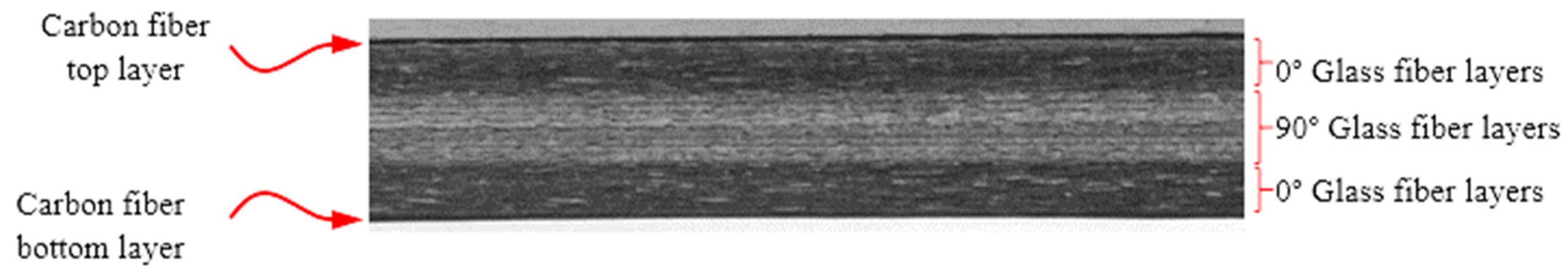
2.1. Hybrid Composite Laminates
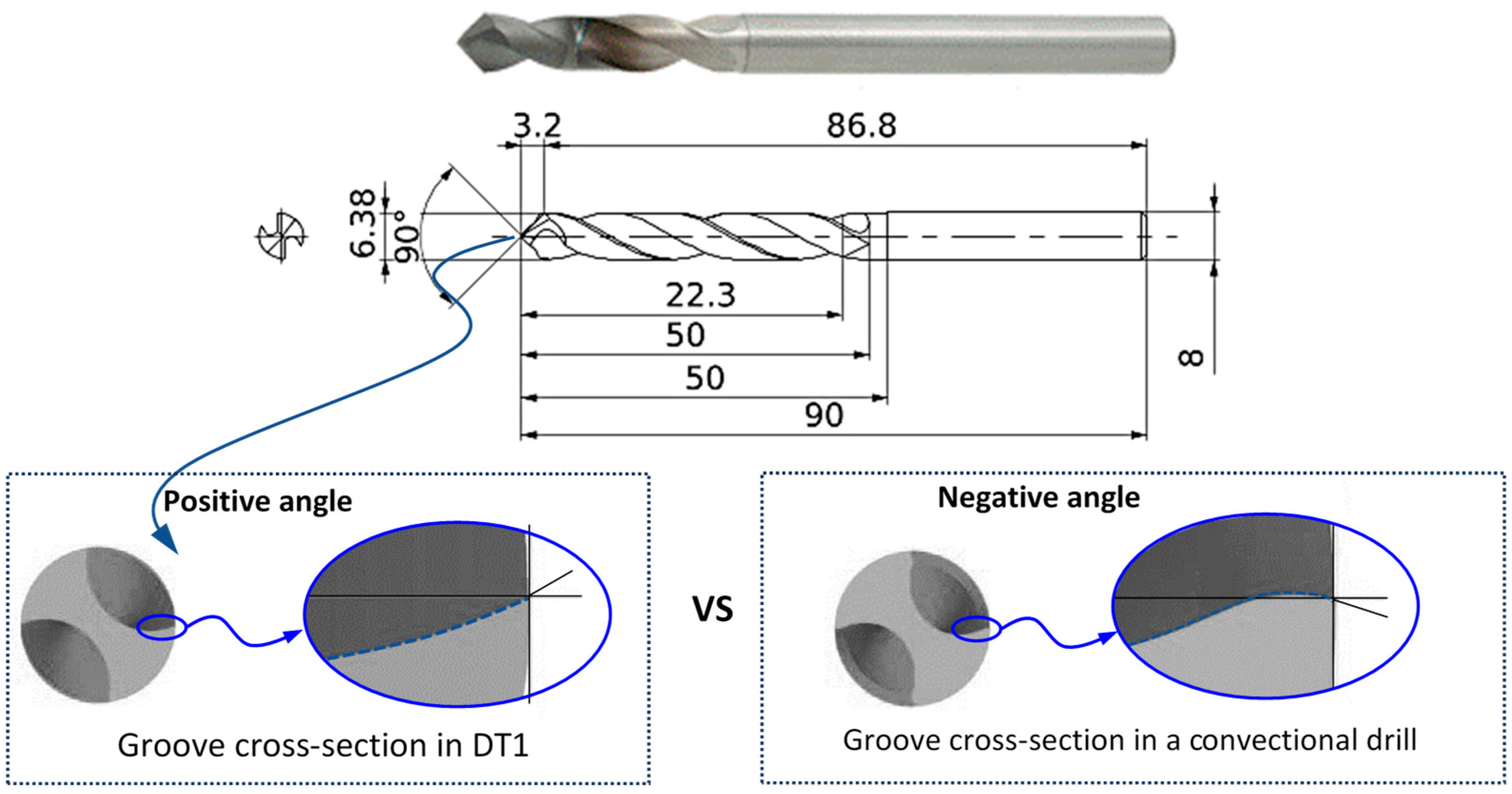
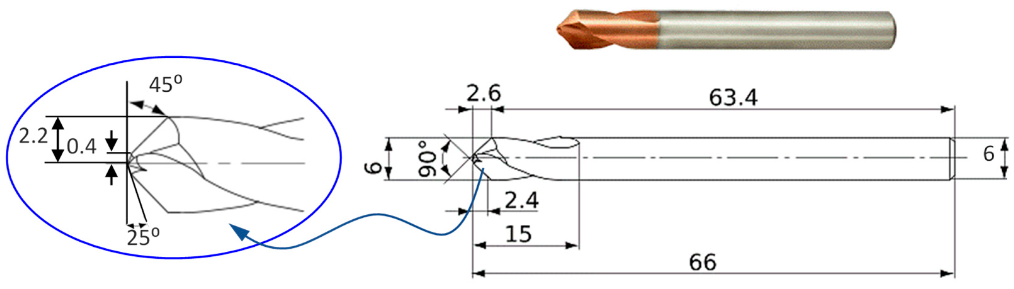
The plates used in this study were manufactured using two types of prepegs, creating a sandwich structure. The wings consisted on a single layer of twill weave carbon fibers (3K) with a thickness of 0.2 mm and a density of 200 g/m2. The core consisted of a laminate with unidirectional plies of G10 style glass fiber with a density of 200 g/m2 and a thickness of 0.112 mm. The plates were manufactured using epoxy resin as matrix material. The process involved pressing the materials (prepegs) in a hot press machine (3C Group Web Sales SL, Coruña, Spain), and subsequently, curing them in an oven (3C Group Web Sales SL, Coruña, Spain).
The stacking sequence of the core was [0°13/90°25/0°13] with 25.5% of the glass fiber first part oriented at 0°, 49% at 90° in the middle part, and another 25.5% at 0° for the third part. A cross-section of the material can be observed in Figure 1.

2.2. Drill Bits

Two drilling tools have been tested, provided by Mitsubishi Materials (Mitsubishi Materials España S.A., Valencia, Spain). These tools were chosen due to their 90° point angle, which helped reduce thrust force and minimize delamination. However, they exhibited notable differences in geometry.
The first tool used was the MCC0638 model, referred to as DT1 (Drill Tool 1) in this study. This tool was a diamond-coated carbide tool manufactured using Chemical Vapor Deposition (CVD) techniques. It featured a geometry specifically designed for drilling CFRP and CFRTP (Carbon Fiber Reinforced Thermo-Plastics) materials. The cutting-edge rake angle was strengthened in the vertical direction along the rotation axis. Additionally, at its outermost periphery, the cutting-edge rake angle maintained a positive angle, in contrast to the negative angles commonly found in conventional drills. An image of the whole geometry is presented in Figure 2.
The second tool was the model DLE0600, named DT2 (Drill Tool 2) in this work. This drill bit was chosen for its coating process method. It is an ultra-micro-grain carbide tool with a Physical Vapor Deposition coated cemented carbide grade and greatly improved wear resistance. This tool had a thinning at the drill point with an X shape. It was suitable for drilling metallic materials, including both ferrous and non-ferrous. The tool had a point angle of 90°, except for the first 0.4 mm, which had a point angle of 130°. This and other dimensions of the tool can be seen in Figure 3.

2.3. Cutting Conditions
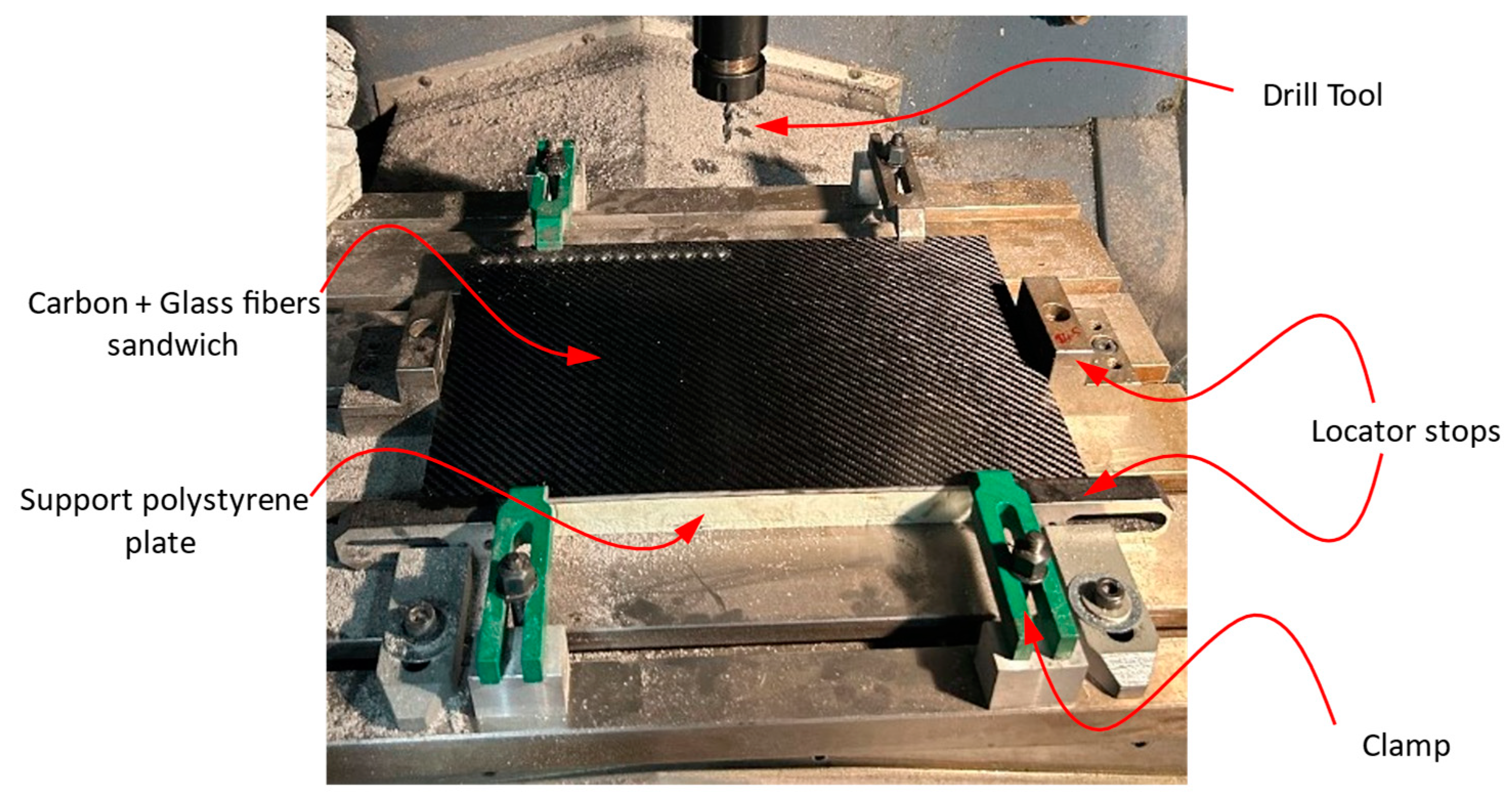
Each drill tool machined 1403 holes, equivalent to completing one and a half plates of carbon/glass hybrid laminate. The spindle speed was set at 5831 rev/min, and the feed rate was set at 599 mm/min. The tool manufacturer provided these cutting conditions for drilling carbon/epoxy laminates with DT1 because the geometry and the coating were optimized to work at HSM. Hence, they were taken as reference values, given that DT2 lacked specific cutting conditions for drilling composite materials. However, drill bit DT2 included these values as “recommended cutting conditions” for a tool with a point angle of 90° when drilling mild steel. These conditions were applicable in this case (Figure 3).
The drilling experiments were carried out without the use of coolant or lubricant. The drilled holes penetrated through the entire panel thickness of the sandwich structure, with the drill tool extending beyond the underside by 5.7 mm.

2.4. Set-Up

The sandwich plates are securely fastened to the worktable using four clamps and four locator stops, as depicted in Figure 4. The bottom face of each sandwich plate is sup-ported on an extruded polystyrene plate. This polystyrene plate includes a complete matrix of predrilled holes placed in the same positions as the holes to be drilled in the sandwich plate. Its purpose is to function as a backing plate, preventing displacements and deformations in the primary plates and minimizing delamination at the exit points.
Throughout the machining process, multiple stoppages were scheduled to capture microscopic images (using an Olympus SZ61 microscope (Evident, Tokyo, Japan) of the tool edges and their neighboring regions. The pauses were scheduled following the completion of machining for 15, 30, 91, 183, 274, 549, 1037, and 1403 holes. Each stop was planned to coincide with the number of holes required to complete a full row.

2.5. Damage Extension Assessment

Damage inspection was conducted on the outer layers of the drilled sandwich plates to evaluate the extent of machining-induced damage. The dimensions of delamination damage are measured using software integrated with an optical microscope (Evident, Tokyo, Japan). The software automatically calculates the area value of a closed line selected by the user. Delamination type I appears when the fibers are bent into the machining line, causing surface damage to the part. Delamination type II occurs when fibers protrude from the machined edge [58]. An example of both delaminations is shown in Figure 5. As depicted in this image, a good-quality image is obtained from the microscope, facilitating the quantification the two possible types of delamination.
Because the typical delamination factor (Fd) does not account for the actual area of delamination damage, the equivalent delamination factor (Fed) is used in this study. This dimensionless factor is calculated as the hole area plus the damaged area between the hole area, as shown in Equation (1), where Ad is the delaminated area in the vicinity of the drilled hole, and A0 is the nominal area of the hole (Figure 5).
F e d = A 0 + A d A 0

3. Results and Discussion

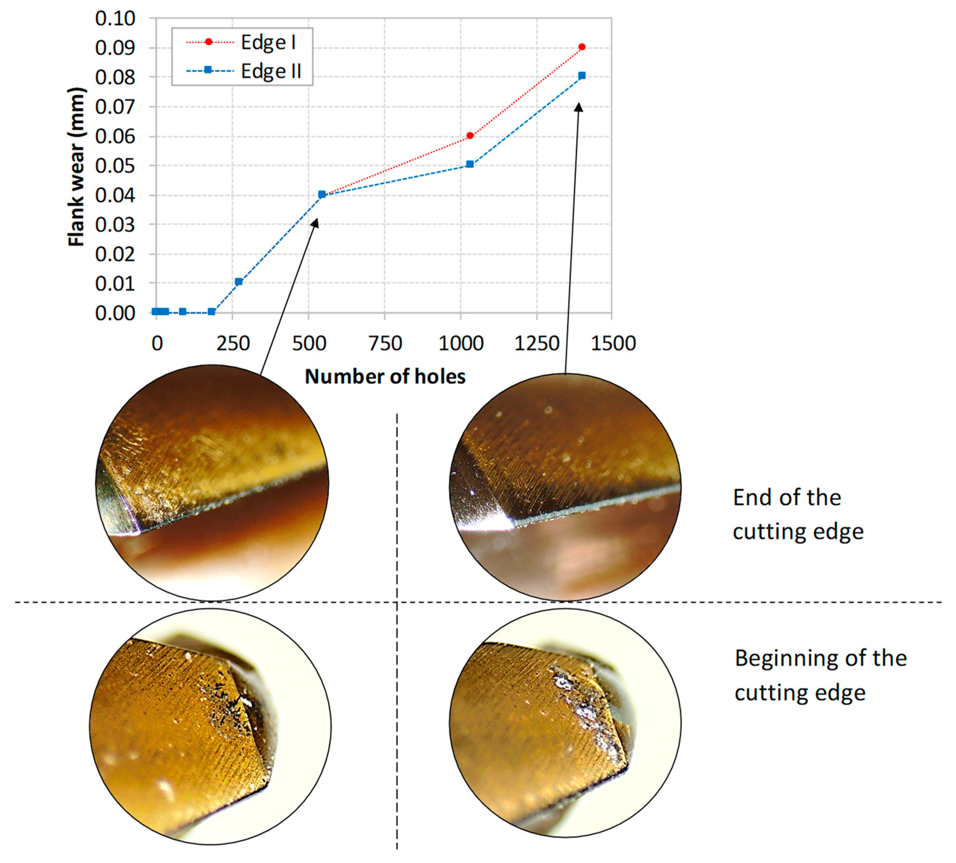
3.1. Flank Wear Evolution

The results of flank wear evolution are evaluated on both edges of both tools. Figure 6 depicts three images representing different stages of cutting edge wear for DT1.
In these images, it can be beheld that the diamond coating is mostly fractured from the flank face of the drill at the end of the cutting edge. This fracture area was quite significant, with a length ranging between 0.6–1 mm, while the tool’s tip wear was almost negligible. During the evolution of the flank wear, minor wear was observed in the initial stages of machining (approximately the first 250 holes). Suddenly, wear increased between the 250–550 drilled holes, after which the flank wear was maintained following the typical wear evolution curve. It can be appreciated that, due to the disappearance of the coating, there is material burned because of the high cutting speed.
It is important to mention that this drill is specifically designed for cutting carbon fibers. However, Mkaddem et al. [59] proved that when cutting GFRP (Glass Fiber Reinforced Polymer), the CVD coating undergoes the harsher mode of abrasion causing a deep wear pattern. This was justified because during the tests, it was observed that cutting glass fibers results in sharp fragments and brittle fractures, while cutting carbon fibers produces finer particles. The size of these fragments, known as ‘chips’, varies with cutting time and plays a significant role in managing friction trends. Sharp glass fiber particles released during cutting form a tribo-system, leading to increased interfacial friction.
When the diamond coating on the drill becomes fractured, it leads to increased thrust forces and torques. Consequently, the increased thrust forces push out the bottom plies of the laminate, eventually causing delamination. However, in this scenario, the coating at the beginning of the cutting edge and chisel edge of the drill remains intact, which helps reduce push-down delamination. This observation was made by Karpat et al. [42] while drilling CFRP materials at high speed. Mkaddem et al. [59] explained this phenomenon, suggesting that finer particles released during cutting carbon/epoxy likely adhere to the debris in the matrix, forming a thin film on the flank face. This film softens the contact and reduces pressure as the cutting length increases.
A similar flank wear trend is observed for DT2, as depicted in Figure 7. Unlike the CVD coating, the PVD coating layer deteriorates rapidly, making the fine thickness of the coating more vulnerable to abrasive fibers. This condition affects its ability to cut as cleanly as the other tool. The images show that the coating undergoes a mild abrasion regime with regular material removal progression (Figure 7). The observed abrasion marks on the worn layer are shallow and tend to be more discrete when drilling GFRP specimens according to [59]. This can be explained by a combination of two mechanisms. First, the removal mode leads to the separation of fine grains from the coating, leaving a powdery form without a visible pattern. Second, the released grains contribute to the formation of a potential film that softens the conditions at the interface. When compared to the CVD coating, the PVD insert displays notably reduced flank wear during cutting of carbon/glass/epoxy specimens.

3.2. Cutting Edge Rounding

The blunting of the cutting edge occurred on all drills tested in this study. Despite the appearance of the worn surfaces of the coated, both tools showed gradual wear. However, in the case of DT2, cutting edge rounding is more severe than in DT1. In the case of tool 1, the diamond coating was flaked off on small, isolated locations. However, the edge remains quite sharp, even considering extensive blade face wear, which will have a significant positive impact on the delamination of the material, and it will not be the primary factor limiting the drill’s life.
As depicted in Figure 8a, the cutting edge of the diamond-coated tool retained its sharpness even after completing 1037 drilling cycles. Although the diamond coating flaked off in some areas, this tool still exhibited the best performance in regions where the coating remained intact. The diamond coating showed minimal gradual wear, indicated by the very low cutting edge rounding, and no signs of chippings or micro fractures were observed. A similar evolution was observed by Wang et al. [27] when drilling CFRP laminates using a diamond-coated drill.
Figure 8b presents the edge wear progression for DT2 after the same number of holes. The cutting edge became dull as the number of holes drilled increased. However, at up to 93 holes, no significant tool wear was observed, and there were no signs of micro fractures or grain pullouts. As the drilling process continued, the cutting edge became dull, and the coating on the edge and flank surfaces wore off gradually, as discussed in the previous section. Signs of micro fractures and chipping, which are common in this type of drill bits, became evident [27].

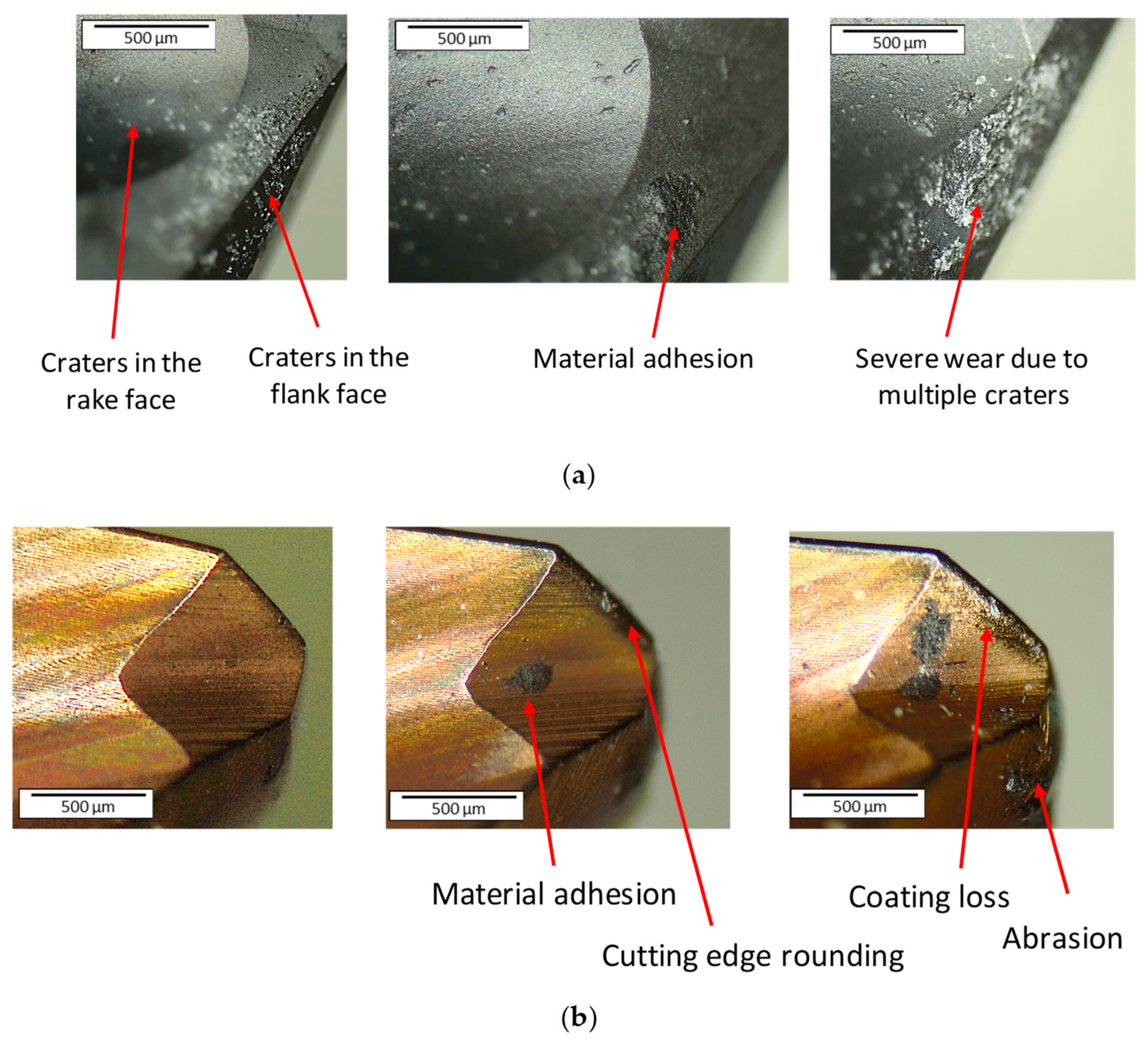
3.3. Craters and Material Adhesion

Finally, in Figure 9, other wear mechanisms are shown for each tool. For tool DT1, material adhesion on the flank face was observed near the drill bit tip (as seen in Figure 9a). Craters were also detected in the rake surface during machining, increasing in number and size due to the abrasive character of the fibers. Craters are generated due to the friction of the chip on the tool rake face. In Figure 9b, material adhesion and coating loss were identified as the wear mechanism of this tool, and they are located in the drill bit tip. The crater defect was barely observed, which means that the coating process based on Physical Vapor Deposition generates excellent adhesion of the coating to the base metal.
These craters in the rake surface increase friction and, therefore, the temperature. This situation can be beneficial since, according to other studies [33], a rise in temperature controls and even causes a decrease in the effect of delamination.

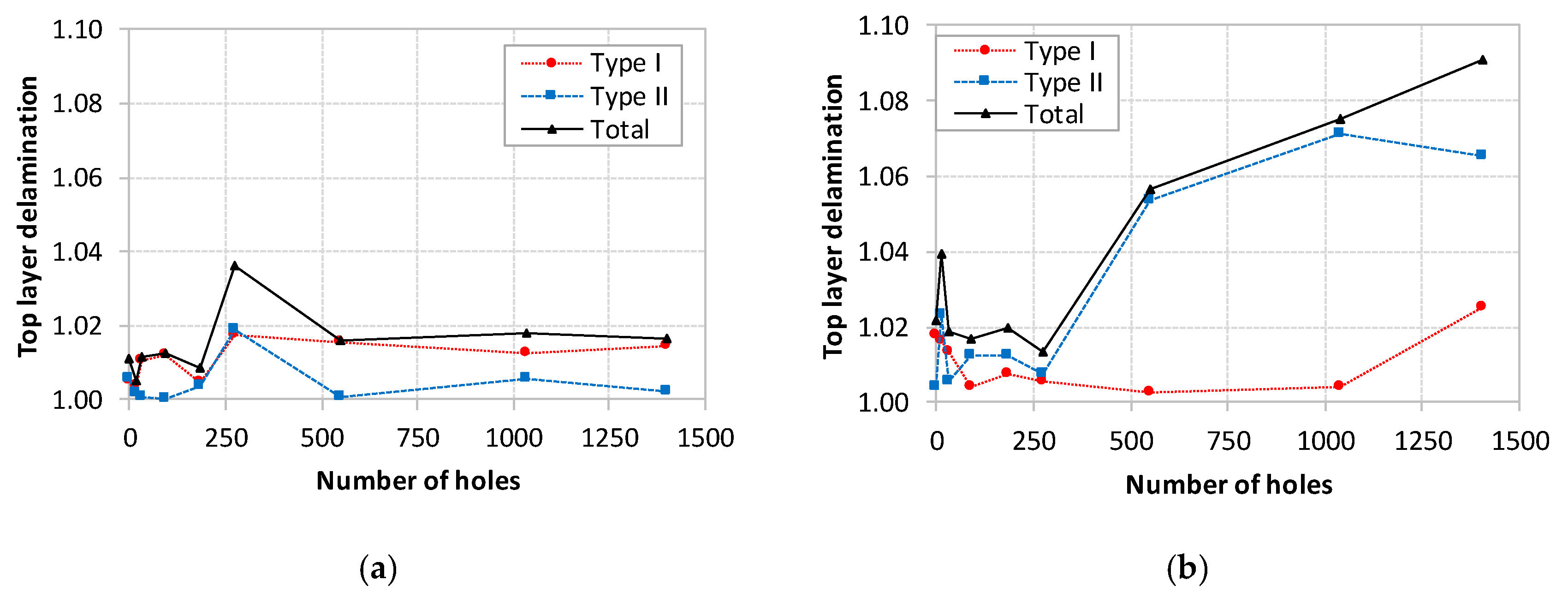
3.4. Entry Delamination Damage (Peel-Up)

The results of the delamination factor at the hole entry (Peel-up delamination) are presented in Figure 10. In the graphic, the damage has been quantified as delamination type I or II, following the previously mentioned definitions, just like the sum of both.
On the one hand, delamination type I in both tools is quite similar, reaching maximum values of 1.02 for DT1 and nearly 1.03 for DT2. While the entry delamination for DT1 remains practically constant throughout the machining, DT2 obtains practically less damage up to 1000 holes. Karpat et al. [42] explained this phenomenon observed in drill bits with a double point angle. In optimal drilling conditions based on a conventional drill geometry, the thrust force and torque are distributed in the only drilling edge. If the design of the drill incorporates a secondary cutting edge, this leads to reduced exit thrust forces. At the same time, it is important to note that the chip formation process in CFRP laminates consists of shearing and brittle fracturing of the fibers. As the feed increases, due to larger loads, fibers are crushed easier and dominant chip formation mechanism becomes the brittle fracturing of the fibers. This may explain the plateau in peel-up with the high feed as shown in Figure 11.
On the other hand, delamination type II is clearly higher in tool DT2, reaching values of 1.07. This can be explained because the roundness of the edge discussed in Section 3.2, does not allow for completely cutting the fibers, and delamination and uncut fibers are clearly visible. Observing the pictures in Figure 11, it is possible to confirm the bad quality of the hole in the second case. Not only poorly cut fibers are visible, but there is also a problem with the inner finish of the hole related to the fuzzing of the fibers, which increases with the number of drilled holes. Tool one has a cleaner cut due to its sharp edges, generating less fuzzing.
However, it is relevant to mention that delamination type II, related to fraying and fuzzing, can be eliminated by reworking, providing a hole with improved quality. This is something not desirable in terms of productivity because it increases the machining time, but in terms of mechanical behavior, there is neither a critical influence on the fiber dominated strength under tensile load nor onto the matrix dominated flexural strength. Therefore, it can be said, that the borehole itself is by far the most strength limiting factor, whereas the machining quality seems to be minor relevant for the strength behavior in drilled thermoplastic CFRP laminates under static loading [60].

3.5. Exit Delamination Damage (Push-Down)

At the hole exit, delamination type I shows similar values in both tools. It is maintained between 1 and 1.02, as can be seen in the plots from Figure 12, which is considered quite low. This is mainly due to the backing polystyrene support plate placed under the main specimen as it has been reported in previous works [6,11]. However, delamination type II presents a different behavior for both drills, similar to the one commented with entry delamination. In the case of DT1, delamination type II is almost nonexistent during all machining. Nevertheless, for DT2, this defect is reduced concerning the entry delamination due to the backing polystyrene support between approximately 250–1000 holes. Still, from this point, and due to the increased wear, it presents a growing trend that reaches values much higher than entry delamination (reaching up 1.16). Several authors concluded in theirs studies that the uncut fibers and fuzzing do not present a clear trend at the exit of the hole, and when tool wear increases, distribution is markedly less dependent on the fiber orientation angle [61,62]. This effect can be appreciated in Figure 13, where the surface shows the fuzzing effect again, but more severe, due to the increase in the edge rounding.
The direct effect of fuzzing and type II delamination is that the hole exit’s diameter is slightly smaller than at the entry because the tool cannot cut the fibers. This could be a relevant problem with narrow tolerances. As it was mentioned before, type II delamination can be eliminated easily by re-drilling. If these defects are eliminated, a high-quality drill hole, especially for DT1 is observed. This is a desirable goal to eliminate the reduction of mechanical properties that implies the appearance of severe delamination, especially when the components are subjected to cycled loads.

4. Conclusions

The study has systematically examined the impact of two distinct drill bits, featuring similar geometries but differing coatings, on the machining of a Carbon-Glass Fiber hybrid material under high-speed conditions. The main conclusions derived from this study are presented in the subsequent paragraphs:
  • Identification of Wear Mechanisms: The examination of both tools has revealed distinct wear mechanisms. Material adhesion is evident in both cases, with DT1 exhibiting multiple craters on the rake and flake face positioned at the cutting edge’s extremity. In contrast, DT2 experiences substantial coating loss and flank wear at its tip.
  • PVD Coating Performance: In the context of drilling carbon-glass fiber/epoxy polymer hybrid material, the PVD coating demonstrates a more uniform and subdued wear pattern across both edges compared to CVD. Consequently, DT1’s flank wear values range from 0.6 mm to 1 mm, whereas DT2’s values remain below 0.1 mm.
  • Delamination Factor Analysis: The assessment of delamination factor encompassing both type I and type II delamination at hole entry and exit elucidates that, in general, DT1 either matches or surpasses DT2’s delamination factor values.
  • Type II Delamination and Fuzzing: For type II delamination, DT2 exhibits a delamination factor within the range of 1.06 to 1.08, surpassing DT1’s values of approximately 1.02. This discrepancy stems from wear-induced edge roundness in DT2, which compromises the material-cutting ability, leading to uncut fibers surrounding the hole and a deteriorated inner hole surface.
  • Delamination Behavior at Hole Exit: Delamination type I at the exit hole, marked by a delamination factor of 1.00, registers a reduction compared to entry hole conditions (delamination factor values between 1 and 1.02). The use of a polystyrene support plate contributes to this effect. Meanwhile, delamination type II curtails internal material damage.
  • Effects on Hole Diameter: The combined impact of fuzzing and type II delamination manifests in a slightly reduced diameter at the hole exit relative to its entry point (0.035%). The inability of the tool to effectively cut the material leads to this outcome.
  • Comparative Coating Performance: In comparing CVD and PVD coatings, DT1 emerges as a viable option for ensuring hole quality. In some scenarios, DT2 even exhibits superior machining quality, particularly concerning delamination type I, primarily at the hole entry. Nevertheless, achieving optimal hole quality would necessitate post-machining reworking to mitigate the effects of fuzzing and uncut fibers.
With a solid foundation in understanding the tool behavior, future research could extend through the design of experiments aimed at tailoring cutting conditions (spindle speed and cut feed) to the specific composite composition and tool coatings, with the objective of minimizing delamination and tool wear.
For tool manufacturers, there is potential to delve deeper into wear mechanism analysis using techniques such as Energy Dispersive Spectroscopy and Scanning Electron Microscopy. Additionally, evaluating the efficacy of tool geometry could be accomplished using the Finite Element Method applied to a 3D model encompassing both the tool and workpiece, offering insights into the anticipated operational behavior.

Author Contributions

Conceptualization, S.C.G., M.D.M. and N.F.; methodology, S.C.G., M.D.M., A.M.-S. and N.F.; formal analysis, M.D.M. and A.M.-S.; investigation, S.C.G. and M.D.M.; resources, S.C.G., A.M.-S. and N.F.; data curation, M.D.M. and A.M.-S.; writing—original draft preparation, S.C.G. and M.D.M.; writing—review and editing, A.M.-S. and N.F.; visualization, S.C.G. and N.F.; supervision, N.F.; project administration, N.F.; funding acquisition, N.F. All authors have read and agreed to the published version of the manuscript.

Funding

This research was funded by Generalitat Valenciana under the project GV/2021/060.

Institutional Review Board Statement

Not applicable.

Informed Consent Statement

Not applicable.

Data Availability Statement

All data that support the findings of this study are included within the article.

Conflicts of Interest

The authors declare no conflict of interest. The funders had no role in the design of the study, in the collection, analyses, or interpretation of data, and in the writing of the manuscript, or in the decision to publish the results.

References

  1. Belgacem, L.; Ouinas, D.; Viña Olay, J.A.; Amado, A.A. Experimental Investigation of Notch Effect and Ply Number on Mechanical Behavior of Interply Hybrid Laminates (Glass/Carbon/Epoxy). Compos. Part B Eng. 2018, 145, 189–196. [Google Scholar] [CrossRef]
  2. Murugan, R.; Ramesh, R.; Padmanabhan, K. Investigation on Static and Dynamic Mechanical Properties of Epoxy Based Woven Fabric Glass/Carbon Hybrid Composite Laminates. Procedia Eng. 2014, 97, 459–468. [Google Scholar] [CrossRef]
  3. Yu, J.; Pan, Z.; Ye, W.; Li, Q.; Wu, Z. Dynamic Temperature Field and Drilling Damage Mechanism of Plain Woven Carbon/Glass Hybrid Composites. Compos. Struct. 2023, 304, 116375. [Google Scholar] [CrossRef]
  4. Geier, N.; Davim, J.P.; Szalay, T. Advanced Cutting Tools and Technologies for Drilling Carbon Fibre Reinforced Polymer (CFRP) Composites: A Review. Compos. Part A Appl. Sci. Manuf. 2019, 125, 105552. [Google Scholar] [CrossRef]
  5. Nagy, S.R.; Pop, A.B.; Titu, A.M. Determination of processing precision of hole in industrial 2 plastic materials. Polymers. 2023, 15, 347. [Google Scholar] [CrossRef] [PubMed]
  6. Feito, N.; Díaz-Álvarez, J.; Díaz-Álvarez, A.; Cantero, J.L.; López-Puente, J.; Miguelez, H. Influence of Tool Geometry in Drilling CFRP. In Proceedings of the 16th European Conference on Composite Materials, ECCM 2014, Seville, Spain, 22–26 June 2014. [Google Scholar]
  7. Grilo, T.J.; Paulo, R.M.F.; Silva, C.R.M.; Davim, J.P. Experimental Delamination Analyses of CFRPs Using Different Drill Geometries. Compos. Part B Eng. 2013, 45, 1344–1350. [Google Scholar] [CrossRef]
  8. Davim, J.P.; Rubio, J.C.; Abrao, A.M. A Novel Approach Based on Digital Image Analysis to Evaluate the Delamination Factor after Drilling Composite Laminates. Compos. Sci. Technol. 2007, 67, 1939–1945. [Google Scholar] [CrossRef]
  9. Sorrentino, L.; Turchetta, S.; Bellini, C. A new method to reduce delaminations during drilling of FRP laminates by feed rate control. Compos. Struct. 2018, 186, 154–164. [Google Scholar] [CrossRef]
  10. Khashaba, U.A.; El-Sonbaty, I.A.; Selmy, A.I.; Megahed, A.A. Machinability analysis in drilling woven GFR/epoxy composites: Part I—Effect of machining parameters. Compos. Part A Appl. Sci. Manuf. 2010, 41, 391–400. [Google Scholar] [CrossRef]
  11. Tsao, C.C.; Hocheng, H. Effects of exit back-up on delamination in drilling composite materials using a saw drill and a core drill. Int. J. Mach. Tools Manuf. 2005, 45, 1261–1270. [Google Scholar] [CrossRef]
  12. Shyha, I.; Soo, S.L.; Aspinwall, D.; Bradley, S. Effect of laminate configuration and feed rate on cutting performance when drilling holes in carbon fibre reinforced plastic composites. J. Mater. Process. Technol. 2010, 210, 1023–1034. [Google Scholar] [CrossRef]
  13. Tsao, C.C.; Hocheng, H. Taguchi analysis of delamination associated with various drill bits in drilling of composite material. Int. J. Mach. Tools Manuf. 2004, 44, 1085–1090. [Google Scholar] [CrossRef]
  14. Al-wandi, S.; Ding, S.; Mo, J. An approach to evaluate delamination factor when drilling carbon fiber-reinforced plastics using different drill geometries: Experiment and finite element study. Int. J. Adv. Manuf. Technol. 2017, 93, 4043–4061. [Google Scholar] [CrossRef]
  15. Davim, J.P.; Reis, P. Drilling carbon fiber reinforced plastics manufactured by autoclave—Experimental and statistical study. Mater. Des. 2003, 24, 315–324. [Google Scholar] [CrossRef]
  16. Karimi, N.Z.; Heidary, H.; Minak, G. Critical thrust and feed prediction models in drilling of composite laminates. Compos. Struct. 2016, 148, 19–26. [Google Scholar] [CrossRef]
  17. Davim, J.P.; Reis, P.; António, C.C. Drilling fiber reinforced plastics (FRPs) manufactured by hand lay-up: Influence of matrix (Viapal VUP 9731 and ATLAC 382-05). J. Mater. Process. Technol. 2004, 155, 1828–1833. [Google Scholar] [CrossRef]
  18. Shyha, I.; Aspinwall, D.; Soo, S.L.; Bradley, S. Drill geometry and operating effects when cutting small diameter holes in CFRP. Int. J. Mach. Tools Manuf. 2009, 49, 1008–1014. [Google Scholar] [CrossRef]
  19. Fernández-Pérez, J.; Cantero, J.L.; Díaz-Álvarez, J.; Miguélez, M.H. Hybrid Composite-Metal Stack Drilling with Different Minimum Quantity Lubrication Levels. Materials 2019, 12, 448. [Google Scholar] [CrossRef]
  20. Giasin, K.; Ayvar-Soberanis, S.; Hodzic, A. The effects of minimum quantity lubrication and cryogenic liquid nitrogen cooling on drilled hole quality in GLARE fibre metal laminates. Mater. Des. 2016, 89, 996–1006. [Google Scholar] [CrossRef]
  21. An, Q.; Ming, W.; Cai, X.; Chen, M. Study on the cutting mechanics characteristics of high-strength UD-CFRP laminates based on orthogonal cutting method. Compos. Struct. 2015, 131, 374–383. [Google Scholar] [CrossRef]
  22. Markandan, K.; Zhang, Z.; Chin, J.; Cheah, K.H.; Tang, H.-B. Fabrication and preliminary testing of hydroxylammonium nitrate (HAN)-based ceramic microthruster for potential application of nanosatellites in constellation formation flying. Microsyst. Technol. 2019, 25, 4209–4217. [Google Scholar] [CrossRef]
  23. Abrão, A.M.; Rubio, J.C.C.C.; Faria, P.E.; Davim, J.P. The Effect of Cutting Tool Geometry on Thrust Force and Delamination When Drilling Glass Fibre Reinforced Plastic Composite. Mater. Des. 2008, 29, 508–513. [Google Scholar] [CrossRef]
  24. Samuel Raj, D.; Karunamoorthy, L. Cutting Edge—Flatting and Roughness Measurement—To Monitor Blunting and Chipping of the Drill Cutting Edge When Drilling CFRP. Int. J. Adv. Manuf. Technol. 2017, 92, 953–968. [Google Scholar] [CrossRef]
  25. Tsao, C.C.; Hocheng, H. Effect of Tool Wear on Delamination in Drilling Composite Materials. Int. J. Mech. Sci. 2007, 49, 983–988. [Google Scholar] [CrossRef]
  26. Feito, N.; Díaz-Álvarez, J.; Díaz-Álvarez, A.; Cantero, J.H.; Miguélez, M.H. Experimental Analysis of the Influence of Drill Point Angle and Wear on the Drilling of Woven CFRPs. Materials 2014, 7, 4258. [Google Scholar] [CrossRef] [PubMed]
  27. Wang, X.; Kwon, P.Y.; Sturtevant, C.; Lantrip, J. Tool wear of coated drills in drilling CFRP. J. Manuf. Process. 2012, 15, 127–135. [Google Scholar] [CrossRef]
  28. Gaugel, S.; Sripathy, P.; Haeger, A.; Meinhard, D.; Bernthaler, T.; Lissek, F.; Kaufeld, M.; Knoblauch, V.; Schneider, G. A comparative study on tool wear and laminate damage in drilling of carbon-fiber reinforced polymers (CFRP). Compos. Struct. 2016, 155, 173–183. [Google Scholar] [CrossRef]
  29. Qiu, X.; Li, P.; Niu, Q.; Chen, A.; Ouyang, P.; Li, C.; Ko, T.J. Influence of machining parameters and tool structure on cutting force and hole wall damage in drilling CFRP with stepped drills. Int. J. Adv. Manuf. Technol. 2018, 97, 857–865. [Google Scholar] [CrossRef]
  30. Xu, J.; Li, C.; Mi, S.; An, Q.; Chen, M. Study of drilling-induced defects for CFRP composites using new criteria. Compos. Struct. 2018, 201, 1076–1087. [Google Scholar] [CrossRef]
  31. Che, D.; Saxena, I.; Han, P.; Guo, P.; Ehmann, K.F. Machining of carbon fiber reinforced plastics/polymers: A literature review. J. Manuf. Sci. Eng. 2014, 136, 034001. [Google Scholar] [CrossRef]
  32. Su, F.; Zheng, L.; Sun, F.; Wang, Z.; Deng, Z.; Qiu, X. Novel Drill Bit Based on the Step-Control Scheme for Reducing the CFRP Delamination. J. Mater. Process. Technol. 2018, 262, 157–167. [Google Scholar] [CrossRef]
  33. Hocheng, H.; Tsao, C.C. Effects of Special Drill Bits on Drilling-Induced Delamination of Composite Materials. Int. J. Mach. Tools Manuf. 2006, 46, 1403–1416. [Google Scholar] [CrossRef]
  34. Feito, N.; Muñoz-Sánchez, A.; Díaz-Álvarez, A.; Miguelez, M.H. Multi-Objective Optimization Analysis of Cutting Parameters When Drilling Composite Materials with Special Geometry Drills. Compos. Struct. 2019, 225, 111187. [Google Scholar] [CrossRef]
  35. Bilgin, S.; Güler, O.; Alver, Ü.; Erdemir, F.; Aslan, M.; Çanakçı, A. Effect of TiN, TiAlCN, AlCrN, and AlTiN ceramic coatings on corrosion behavior of tungsten carbide tool. J. Australas. Ceram. Soc. 2021, 57, 263–273. [Google Scholar] [CrossRef]
  36. Dabees, S.; Mirzaei, S.; Kaspar, P.; Holcman, V.; Sobola, D. Characterization and Evaluation of Engineered Coating Techniques for Different Cutting Tools—Review. Materials 2022, 15, 5633. [Google Scholar] [CrossRef]
  37. Taheri, R.; Jalali, M.; Al-Yaseri, A.; Yabesh, G. Improving TC drill bit’s efficiency and resistance to wear by graphene coating. Pet. Res. 2022, 7, 430–466. [Google Scholar] [CrossRef]
  38. Aamir, M.; Tolouei-Rad, M.; Giasin, K.; Nosrati, A. Recent advances in drilling of carbon fiber–reinforced polymers for aerospace applications: A review. Int. J. Adv. Manuf. Technol. 2019, 105, 2289–2308. [Google Scholar] [CrossRef]
  39. Wang, X.; Shen, X.; Zeng, C.; Sun, F. Combined influences of tool shape and as-deposited diamond film on cutting performance of drills for CFRP machining. Surf. Coat. Technol. 2018, 347, 390–397. [Google Scholar] [CrossRef]
  40. Iliescu, D.; Gehin, D.; Gutierrez, M.E.; Girot, F. Modeling and tool wear in drilling of CFRP. Int. J. Mach. Tools Manuf. 2010, 50, 204–213. [Google Scholar] [CrossRef]
  41. Hrechuk, A.; Bushlya, V.; M’Saoubi, R.; Ståhl, J.E. Experimental investigations into tool wear of drilling CFRP. Procedia Manuf. 2018, 25, 294–301. [Google Scholar] [CrossRef]
  42. Karpat, Y.; Deger, B.; Bahtiyar, O. Drilling thick fabric woven CFRP laminates with double point angle drills. J. Mater. Process. Technol. 2012, 212, 2117–2127. [Google Scholar] [CrossRef]
  43. Cavatorta, M.P. A comparative study of the fatigue and post-fatigue behavior of carbon-glass/epoxy hybrid RTM and hand lay-up composites. J. Mater. Sci. 2007, 42, 8636–8644. [Google Scholar] [CrossRef]
  44. Nagaraja, K.C.; Rajanna, S.; Prakash, G.S.; Koppad, P.G.; Alipour, M. Studying the effect of different carbon and glass fabric stacking sequence on mechanical properties of epoxy hybrid composite laminates. Compos. Commun. 2020, 21, 100425. [Google Scholar] [CrossRef]
  45. Dong, C.; Davies, I.J. Flexural and tensile strengths of unidirectional hybrid epoxy composites reinforced by S-2 glass and T700S carbon fibres. Mater. Des. 2014, 54, 955–966. [Google Scholar] [CrossRef]
  46. Tan, C.L.; Azmi, A.I.; Mohamad, N. Performance Evaluations of carbon/glass hybrid Polymer composites. Adv. Mater. Res. 2014, 980, 8–12. [Google Scholar] [CrossRef]
  47. Selmy, A.; Abd El-baky, M.A.; Hegazy, D.A. Mechanical properties of inter-ply hybrid composites reinforced with glass and polyamide fibers. J. Thermoplast. Compos. Mater. 2019, 32, 267–293. [Google Scholar] [CrossRef]
  48. Attia, M.A.; Abd El-baky, M.A.; Alshorbagy, A.E. Mechanical performance of intraply and inter-intraply hybrid composites based on e-glass and polypropylene unidirectional fibers. J. Compos. Mater. 2017, 51, 381–394. [Google Scholar] [CrossRef]
  49. Abd El-baky, M.A. Evaluation of mechanical properties of jute/glass/carbon fibers reinforced hybrid composites. Fibers Polym. 2017, 18, 2417–2432. [Google Scholar] [CrossRef]
  50. Franz, G.; Vantomme, P.; Hassan, M.H. A Review on Drilling of Multilayer Fiber-Reinforced Polymer Composites and Aluminum Stacks: Optimization of Strategies for Improving the Drilling Performance of Aerospace Assemblies. Fibers 2022, 10, 78. [Google Scholar] [CrossRef]
  51. Gemi, L.; Köklü, U.; Yazman, Ş.; Morkavuk, S. The Effects of Stacking Sequence on Drilling Machinability of Filament Wound Hybrid Composite Pipes: Part-1 Mechanical Characterization and Drilling Tests. Compos. Part B Eng. 2020, 186, 107787. [Google Scholar] [CrossRef]
  52. Sonkar, V.; Abhishek, K.; Datta, S.; Mahapatra, S.S. Multi-Objective Optimization in Drilling of GFRP Composites: A Degree of Similarity Approach. Procedia Mater. Sci. 2014, 6, 538–543. [Google Scholar] [CrossRef]
  53. Tan, C.L.; Azmi, A.I.; Muhammad, N. Delamination and Surface Roughness Analyses in Drilling Hybrid Carbon/Glass Composite. Mater. Manuf. Process. 2016, 31, 1366–1376. [Google Scholar] [CrossRef]
  54. Krishnaraj, V.; Prabukarthi, A.; Ramanathan, A.; Elanghovan, N.; Senthil Kumar, M.; Zitoune, R.; Davim, J.P. Optimization of Machining Parameters at High Speed Drilling of Carbon Fiber Reinforced Plastic (CFRP) Laminates. Compos. Part B Eng. 2012, 43, 1791–1799. [Google Scholar] [CrossRef]
  55. Gaitonde, V.N.; Karnik, S.R.; Rubio, J.C.; Correia, A.E.; Abrão, A.M.; Davim, J.P. Analysis of Parametric Influence on Delamination in High-Speed Drilling of Carbon Fiber Reinforced Plastic Composites. J. Mater. Process. Technol. 2008, 203, 431–438. [Google Scholar] [CrossRef]
  56. Campos Rubio, J.; Abrao, A.M.; Faria, P.E.; Correia, A.E.; Davim, J.P. Effects of High Speed in the Drilling of Glass Fibre Reinforced Plastic: Evaluation of the Delamination Factor. Int. J. Mach. Tools Manuf. 2008, 48, 715–720. [Google Scholar] [CrossRef]
  57. Rawat, S.; Attia, H. Wear Mechanisms and Tool Life Management of WC–Co Drills during Dry High Speed Drilling of Woven Carbon Fibre Composites. Wear 2009, 267, 1022–1030. [Google Scholar] [CrossRef]
  58. Navarro-Mas, M.D.; Meseguer, M.D.; Lluch-Cerezo, J.; García-Manrique, J.A. Comparison of Different Parameters to Evaluate Delamination in Edge Trimming of Basalt Fiber Reinforced Plastics (Bfrp). Materials 2020, 13, 5326. [Google Scholar] [CrossRef]
  59. Mkaddem, A.; Soussia, A.B.; El Mansori, M. Wear resistance of CVD and PVD multilayer coatings when dry cutting fiber reinforced polymers (FRP). Wear 2013, 302, 946–954. [Google Scholar] [CrossRef]
  60. Meinhard, D.; Haeger, A.; Knoblauch, V. Drilling induced defects on carbon fiber-reinforced thermoplastic polyamide and their effect on mechanical properties. Compos. Struct. 2021, 256, 173–183. [Google Scholar] [CrossRef]
  61. Heisel, U.; Pfeifroth, T. Influence of point angle on drill hole quality and machining forces when drilling CFRP. Proc. CIRP Jan. 2012, 1, 471–476. [Google Scholar] [CrossRef]
  62. Poulachon, G.; Outeiro, J.; Ramirez, C.; André, V.; Abrivard, G. Hole surface topography and tool wear in CFRP drilling. Proc. CIRP 2016, 45, 35–38. [Google Scholar] [CrossRef]
Figure 1. Cross section of the material.
Coatings 13 01440 g001
Figure 2. Dimensions and geometry for drill tool DT1 (all dimensions are in millimeters, except degrees). Detail of the positive cutting-edge rake angle on the periphery of the tip.
Coatings 13 01440 g002
Figure 3. Dimensions and geometry for drill tool DT2. Detail of the tip of the drill (all dimensions are in millimeters, except degrees).
Coatings 13 01440 g003
Figure 4. Experimental device for drilling tests.
Coatings 13 01440 g004
Figure 5. Nominal area of the hole and some examples of delamination type I (area marked in red) and type II (area marked in red) measurement.
Coatings 13 01440 g005
Figure 6. Flank wear evolution for DT1.
Coatings 13 01440 g006
Figure 7. Flank wear evolution for DT2.
Coatings 13 01440 g007
Figure 8. Detail of the cutting edge for (a) DT1 and (b) DT2.
Coatings 13 01440 g008
Figure 9. Different wear mechanisms were observed in the rake face and flank face for (a) DT1 and (b) DT2.
Coatings 13 01440 g009
Figure 10. Delamination damage evolution at the top layer for (a) DT1 and (b) DT2.
Coatings 13 01440 g010
Figure 11. Images taken by optical microscope in the top layer of the material after drilling 549 holes for (a) DT1 and (b) DT2.
Coatings 13 01440 g011
Figure 12. Delamination damage evolution at the bottom layer for (a) DT1 and (b) DT2.
Coatings 13 01440 g012
Figure 13. Images taken by optical microscope in the bottom layer of the material after drilling 1403 holes for (a) DT1 and (b) DT2.
Coatings 13 01440 g013
Disclaimer/Publisher’s Note: The statements, opinions and data contained in all publications are solely those of the individual author(s) and contributor(s) and not of MDPI and/or the editor(s). MDPI and/or the editor(s) disclaim responsibility for any injury to people or property resulting from any ideas, methods, instructions or products referred to in the content.

