Article

Studies on Protective Coatings for Molding Tools Applied in a Precision Glass Molding Process for a High Abbe Number Glass S-FPM3

1
The School of Opto-Electronics Engineering, Changchun University of Science and Technology, Changchun 130022, China
2
Fraunhofer Institute for Production Technology IPT, Steinbachstrasse 17, 52074 Aachen, Germany
3
Shenyang ShenDa Endoscopy Co., Ltd., No13, BeiDaying District, Shenyang 110044, China
4
Laboratory for Machine Tools and Production Engineering (WZL) of RWTH Aachen University, Campus-Boulevard 30, 52074 Aachen, Germany
*
Author to whom correspondence should be addressed.
Coatings 2023, 13(8), 1438; https://doi.org/10.3390/coatings13081438
Submission received: 13 June 2023 / Revised: 4 August 2023 / Accepted: 10 August 2023 / Published: 16 August 2023
(This article belongs to the Special Issue Protective Composite Coatings: Implementation, Structure, Properties)

Abstract

:
Precision glass molding (PGM) is an efficient process used for manufacturing high-precision micro lenses with aspheric surfaces, which are key components in high-resolution systems, such as endoscopes. In PGM, production costs are significantly influenced by the lifetimes of elaborately manufactured molding tools. Protective coatings are applied to the molding tools to withstand severe cyclic thermochemical and thermomechanical loads in the PGM process and, in this way, extend the life of the molding tools. This research focuses on a new method which combines metallographic analysis and finite element method (FEM) simulation to study the interaction of three protective coatings—diamond-like carbon (DLC), PtIr and CrAlN—each in contact with the high Abbe number glass material S-FPM3 in a precision glass molding process. Molding tools are analyzed metallographically using light microscopy, white light interferometry, scanning electron microscopy (SEM), and energy dispersive X-ray spectroscopy (EDX). The results show that the DLC coating improved process durability more than the PtIr and CrAlN coatings, in which the phenomenon of coating delamination and glass adhesion can be observed. To identify potential explanations for the metrological results, FEM is applied to inspect the stress state and stress distribution in the molding tools during the molding process.

Graphical Abstract

1. Introduction

With extensive research on miniaturization and precision in medical endoscopes and laser systems, as well as consumer products like mobile phones, high-precision optical glass components exhibit a wide range of application prospects [1,2,3,4]. For the manufacture of high-precision imaging optics, e.g., for endoscope systems, the avoidance of optical aberrations is elementary. A common aberration is chromatic aberration due to wavelength-dependent refraction, called dispersion. Therefore, glass types with a high Abbe number and corresponding low dispersion are of great interest for various optical applications.
Precision glass molding (PGM) is a highly efficient technology for the replicative manufacturing of glass optics which has been applied in various fields. During PGM, a glass blank is heated above the glass transition temperature (Tg) into a low-viscosity state. The glass blank is pressed to the desired surface shape by applying a force between two precisely manufactured molding tools. The PGM process can be divided into evacuating, nitrogen purging, heating, pressing, holding, and cooling by nitrogen flow [5,6,7]. The molded glass can be used directly without further postprocessing such as grinding or polishing. The mold material is commonly composed of tungsten carbide (WC) due to its high strength and hardness at high temperatures as well as its ability to be precisely machined by means of grinding and polishing [8,9,10]. To protect the WC molding tools from degradation caused by harsh process conditions, a surface protective coating is applied [11,12]. Three groups of surface protective coatings are commonly used [13]: precious metal coatings [14], ceramic hard coatings [15], and carbon-based diamond-like carbon (DLC) coatings [16].
In this study, one protective coating from each of these groups was selected and evaluated in the molding of the high Abbe number glass S-FPM3 (OHARA INC., Abbe number 74.70) material, which is established in the design of endoscopic optical systems. In detail, a PtIr-based precious metal coating, a nitride-based hard coating, CrAlN, and a tetrahedral amorphous carbon (ta-C) coating as a special type of DLC coating were investigated. PtIr has been used in PGM for over a decade due to its chemical inertness when in contact with heated glass [17]. The use of CrAlN coating was demonstrated for the molding of infrared-transmissive chalcogenide glass [18]. Due to the chalcogen-based chemical composition, chalcogenide glasses are characterized by low molding temperatures at about 225 °C. The performance of CrAlN coatings at higher temperatures has not yet been investigated. In addition, ta-C coatings in PGM have become the focus of research in recent years [19,20]. ta-C coatings are hydrogen-free DLC coatings with a high proportion of sp3-hybridization [21]. These coatings are characterized by very high hardness, resistance to high force loads and a low friction coefficient, which favors the flow of glass on the coated molding tools. A promising lifetime of ta-C coating with more than 1000 molding cycles at molding temperatures between 500 to 540 °C without delamination has already been demonstrated [19]. In contrast, a limit on the lifetime of ta-C coating was observed due to the occurrence of graphitization at molding temperatures above 450 °C [22]. The lifetime of ta-C- during the forming of a high Abbe number glass has not yet been investigated.
Degradation mechanisms of the three coatings were enforced by performing molding tests in an industrial PGM machine (GMP-315, Toshiba Machine Co., Ltd., Tokyo, Japan). Surface degradation was analyzed using light microscopy, white light interferometry, scanning electron microscopy (SEM), and energy dispersive X-ray spectroscopy (EDX). The combination of metallographic analysis and finite element method (FEM) analysis can provide a powerful tool for understanding the behavior and performance of coated materials. FEM simulation can give insights into the stress distribution within the coated material, which can help to identify potential failure points and optimize the composition of the coating to reduce stress and increase durability [23]. Metallographic analysis can then reveal additional insights into the micro-structures of the coating or the micro-phases, as well as its adhesion and chemical compositions. There are already several works published [23,24] in coating research based on FEM simulation, however they only focus on the thermal influence on coating behavior. The PGM process is a thermal–mechanical coupled process, which includes the friction between the glass and the molding tool surfaces [25].
In precision glass molding, the Coulomb friction law proves especially valuable as it elucidates the correlation between the frictional force and the normal force, which is crucial in stress analysis, and which relates to the shear stress and contact pressure between the glass material and the molding surfaces [26]. The inputs of the Coulomb friction law are the normal force and the coefficient of friction. The normal force is the force perpendicular to the surfaces in contact, and the coefficient of friction is a dimensionless constant that depends on the materials in contact and other factors. The output of the Coulomb friction law is the frictional force or the shear stress, which is parallel to the surfaces in contact and can cause wear and degradation of the coating [27]. The friction can be either sticking friction or slipping friction, depending on the relative motion between the surfaces [28]. Sticking friction occurs when the surfaces are stationary or move at low speeds, whereas slipping friction occurs when the surfaces move relative to each other.
Because in-depth tribological investigation in and over the glass transition regime is challenging and time-consuming, FEM simulations enable the acceleration of qualitative analysis of frictional behavior and stress situations caused. Therefore, in this study, the combination of metallographic analysis and FEM simulation was used as a novel approach to investigate mold coating degradation in the complex thermo-mechanical PGM process.

2. Materials and Methods

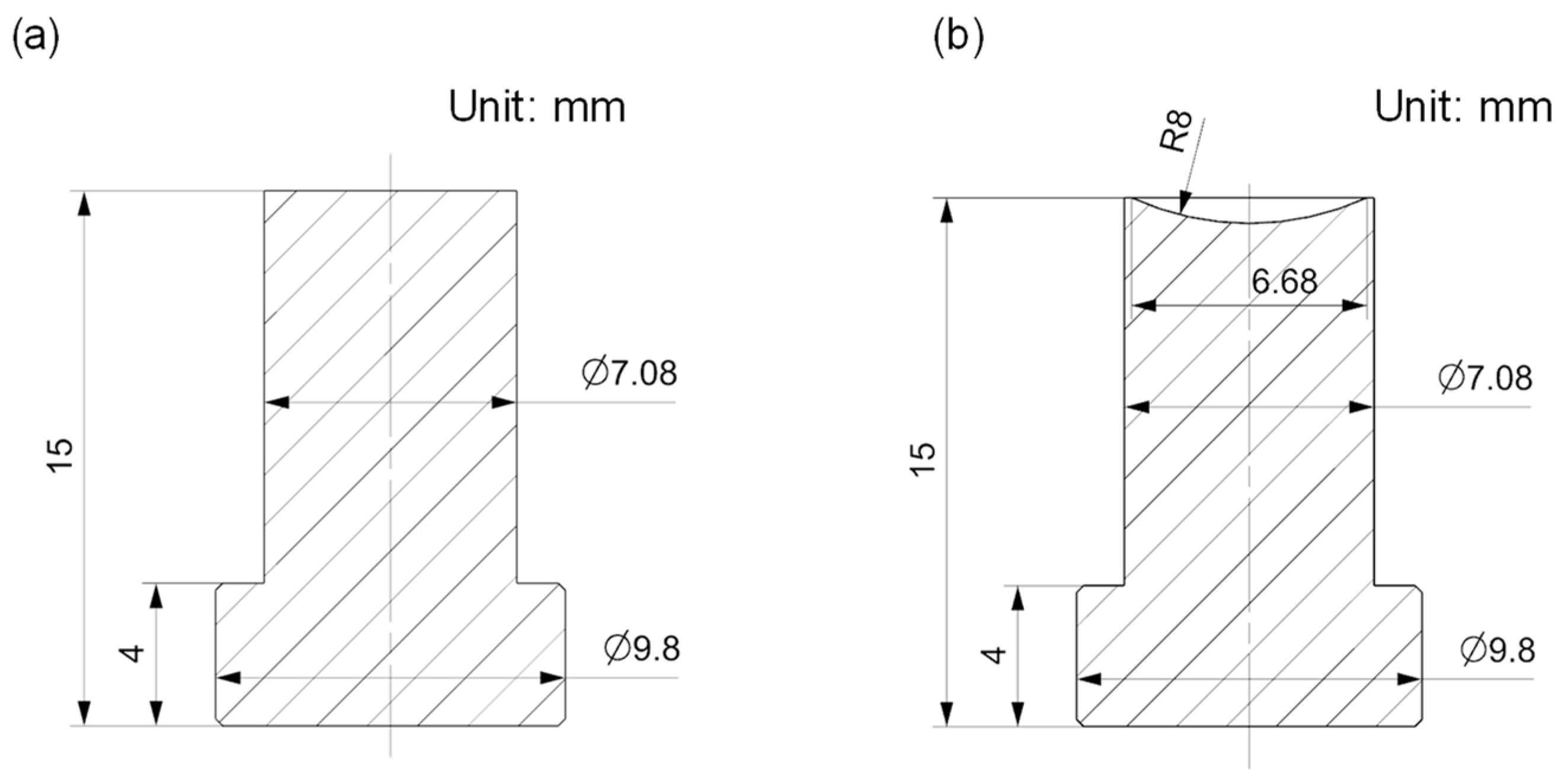
2.1. Sample Preparation

As the mold material, tungsten carbide grade WC100 from NJS Co., Ltd. (Shin-Yokohama, Japan) was used. WC100 is characterized by a binderless WC composition and a small grain size (<0.08 µm), as required for high-precision machining by grinding and polishing [29,30]. Its mechanical properties are shown in Table 1. These parameters were also used as input parameters for the FEM simulation. To reduce the manufacturing effort of test molding tools, a simplified molding tool design was utilized. Contrary to the industrially relevant aspherical molding tool geometry, a spherical concave lower tool with a radius of 8 mm and a plane upper tool were chosen (Figure 1). In order to manufacture the molding tools, an ultra-precision Toshiba ULG100 grinding machine was used. The surface accuracy of the molding tools was a peak-to-value (PV) of less than 250 nm and a surface roughness (Ra) of less than 5 nm. In total, twelve molding tool pairs were prepared for the presented coating studies analyzing three protective coatings, namely, DLC, CrAlN, and PtIr. ta-C coatings as a kind of DLC coating were applied by using the Filtered Cathodic Vacuum Arc (FCVA) technology of Nanofilm Technologies International Ltd. from Singapore. The coating deposition time was approx. 12 min, resulting in an approx. 100 nm DLC coating thickness. CrAlN as well as PtIr coatings were deposited using a CemeCon CC800/9 custom direct current magnetron sputtering (DCMS) unit. The CrAlN and PtIr coating thicknesses applied were approx. 600 nm, resulting from a deposition time of approx. 40 min. DLC and CrAlN coatings were deposited directly on the WC substrate, whereas an approx. 20 nm thick Cr adhesion layer was used for PtIr based on previous studies [31]. As a glass preform, polished spheres with a diameter of Ø4 mm composed of high Abbe number glass S-FPM3 material from the Ohara company were used.

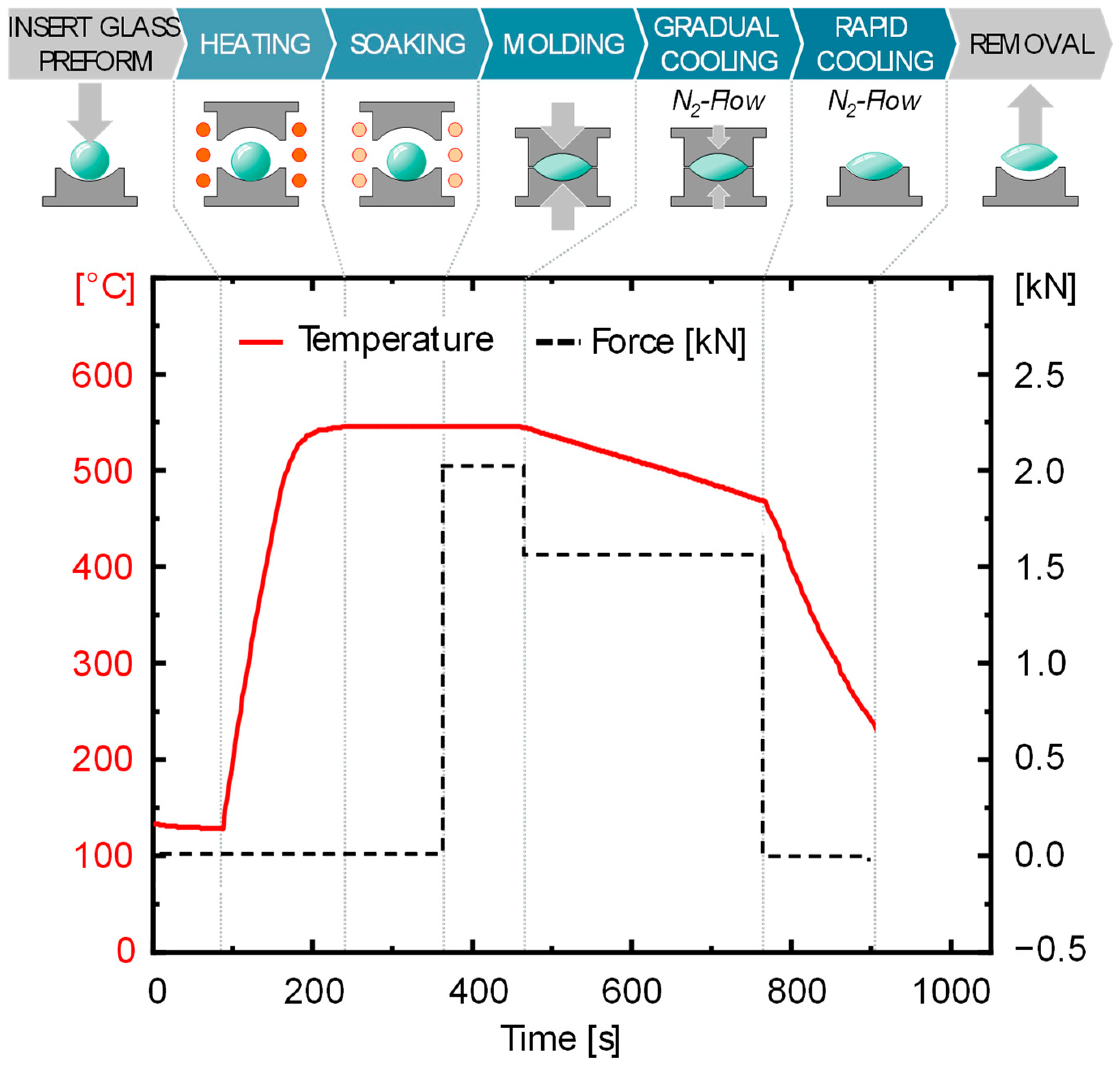
2.2. Molding Experiment

A GMP-315 molding machine manufactured by Toshiba Machine Co., Ltd. (Tokyo, Japan) from Japan was used to study the protection effect of the three protective coatings for molding S-FPM3 glass material. In process preparation, a glass ball was cleaned in ultrasonic baths, blow-dried with a nitrogen flow, visually inspected for impurities and imperfections and then placed into the lower molding tool. During the process (Figure 2), the molding chamber was evacuated to a pressure below 3 Pa. After evacuation, infrared lamps were used to heat the molding tools and the glass ball to the molding temperature. For S-FPM3 glass material, the molding temperature was set to be 540 °C. A preset heating rate of 3 K/s was generated by means of a proportional-integral-derivative (PID) controller. To ensure homogeneous temperature distribution in the molding tools and glass, the temperature was held for 120 s at 540 °C after heating. Then, for molding purposes, the lower mold moved upward, applying a molding force of 2.0 kN for 70 s. After molding, the force was reduced to 1.6 kN while the system was cooled by gradually flooding the process chamber with nitrogen flow with a low cooling of rate 0.2 K/sec down to 480 °C, which is below the glass transition temperature of S-FPM3 (Tg = 496 °C [33]). This controlled cooling stage can improve the form accuracy of the molded optical components. Finally, the system was fast cooled to 200 °C to remove the molded lens and terminate the process cycle. The duration for an entire molding cycle was approximately 15 min.

2.3. Specimen Characterization

To evaluate the degradation of the specimens, the specimens were analyzed before coating, after coating, and after performing the molding experiment. Light microscopy was used to assess the coating quality at a macroscopic scale. A Neon 40 EsB scanning electron microscope from the company Zeiss was used to observe microscopic surface defects of the coatings. For SEM and EDX analysis, an accelerating voltage of 10 kV and a maximum magnification of 25,000× was selected. For quantitative determination of surface quality, the surface roughness Ra of the samples was measured using a white light interferometer (Contour GT-K produced by Bruker Corporation, Singapore). The roughness measurements were made with 20 times magnification (10 × 2), a measuring area of 236 μm × 315 μm, a backscan of 30 μm and a length of 30 μm, using VXI mode and a Gaussian filter.

2.4. FEM Simulation

Stress induced by the precision glass molding process is crucial for the performance and lifetime of the functional coatings [34]. Through FEM modeling, the stress in the tools as well as in the glass can be simulated, and the interpretation regarding coating degradation and damage can be supported. In this work, the commercial simulation software ABAQUSTM by Dassault Systèmes (2019), Vélizy-Villacoublay, France, was used to calculate stress during the thermos-mechanical PGM process. Process parameters of the experiments as well as material properties of WC substrate and S-FPM3 glass were taken into account in terms of boundary conditions. To reduce the simulation effort, a mirrored 2D rotational symmetric simulation model was built, as shown in Figure 3. To include the friction phenomena in the simulation, the Coulomb’s law of friction was applied, where the friction coefficient can be defined freely.

3. Results and Discussion

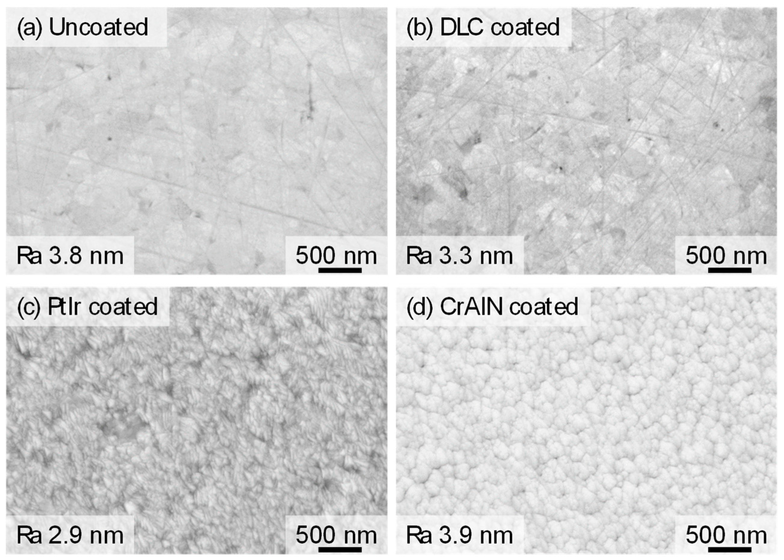
3.1. Initial Surface Conditions (Uncoated Molds)

To determine initial surface conditions, an uncoated molding tool was analyzed. The fabricated uncoated molds showed no macroscopic defects. The surface was smooth and flat, resulting in a surface roughness Ra of less than 5 nm. Microscopic surface analysis by SEM revealed both elongated grooves and microdefects, as shown in Figure 4a. The grooves had a maximum width of 50 nm. The length was up to several micrometers. They are a result of the grinding process. The minimal micro defects (black dots) represent micro cracking, which is typical when grinding brittle hard WC material [35,36].

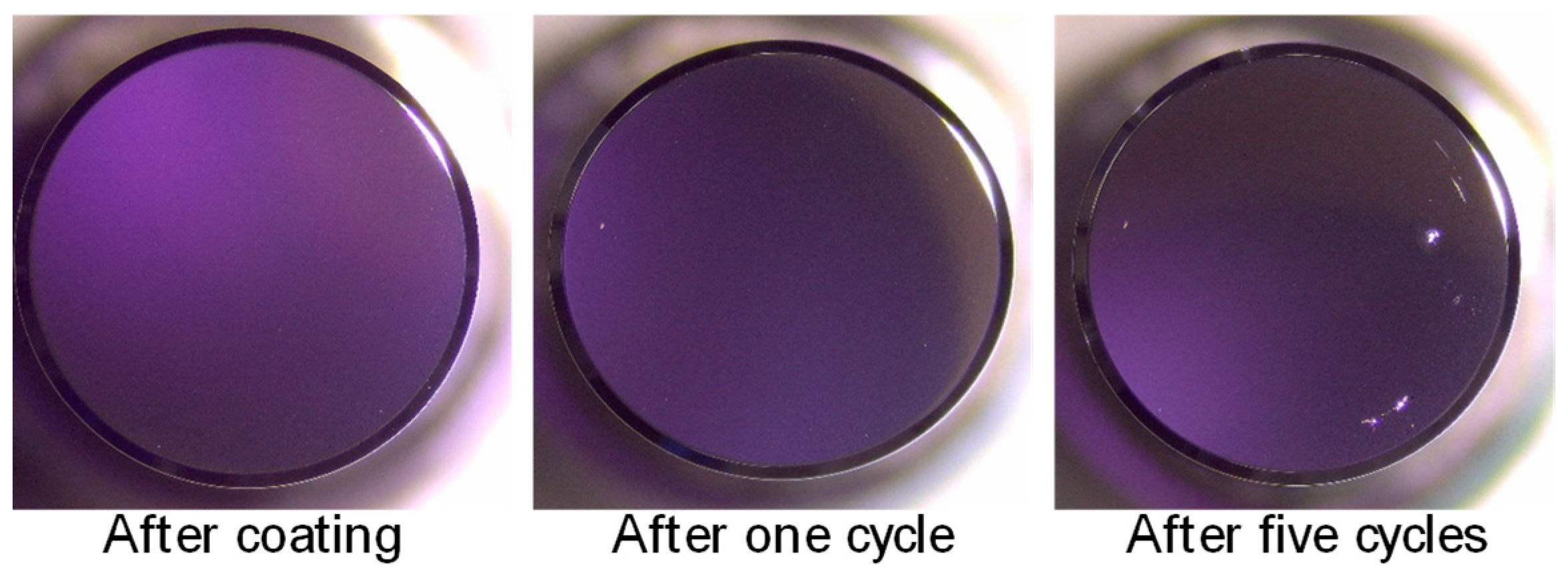
3.2. Coated Surfaces (DLC/PtIr/CrAlN)

Regardless of any applied coating system, the coated molding tools continued to show no macroscopic defects. The coatings used were developed specifically for PGM and were therefore designed for the highest surface quality. The surface roughness Ra for all coated molds remained below 5 nm. However, differences in the surface morphology of the coatings can be seen at the microscopic scale using scanning electron microscopy. Figure 4b shows that the DLC coatings deposited by FCVA technology do not imply any changes in the surface structure. On the other hand, the PtIr and CrAlN coatings produced by magnetron sputtering form surface bulges, as shown in Figure 4c,d. These surface bulges are an indication of a columnar coating microstructure [37]. These coatings are also much thicker than DLC coatings (about five times thicker). As a result, the coating microstructure can cover the original surface structure.

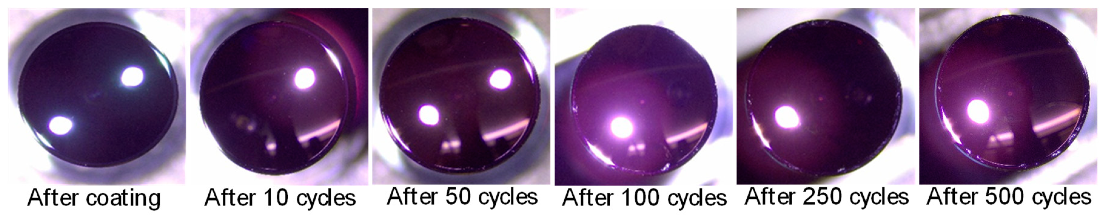
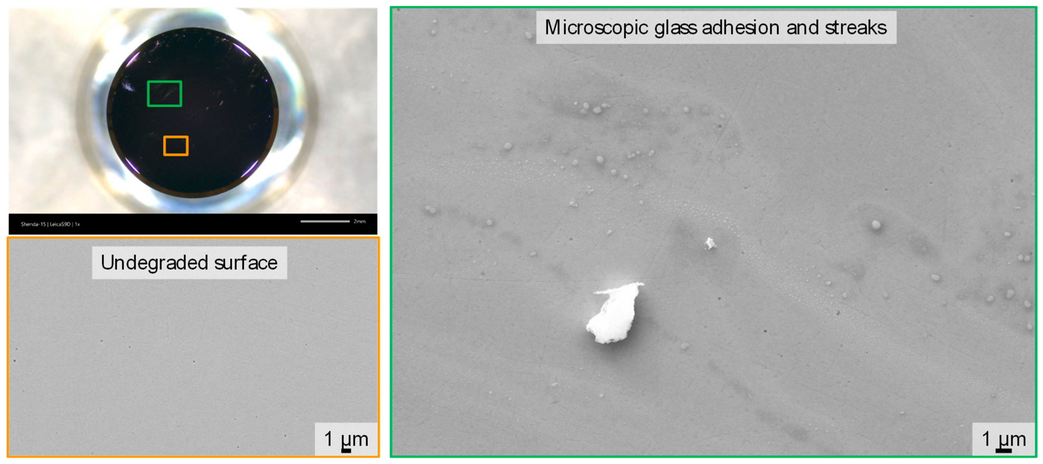
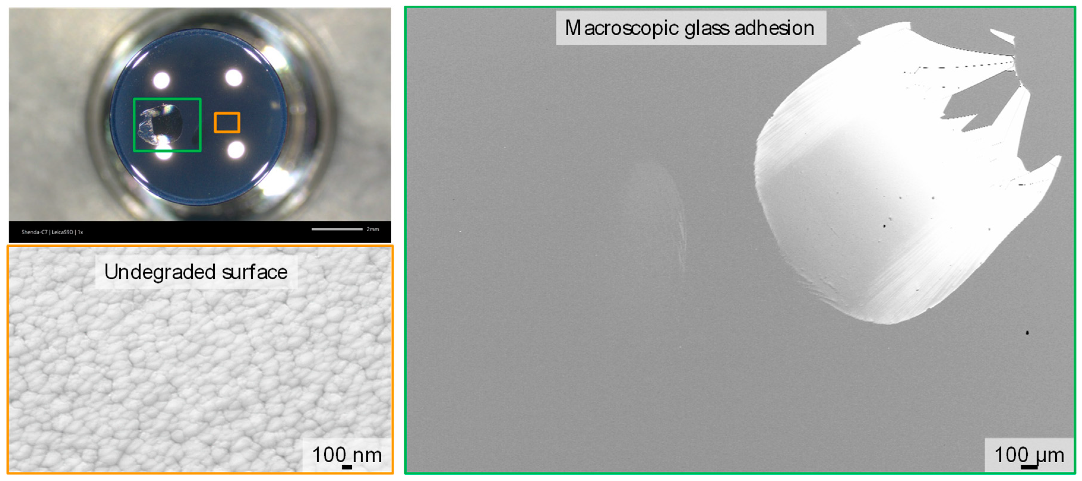
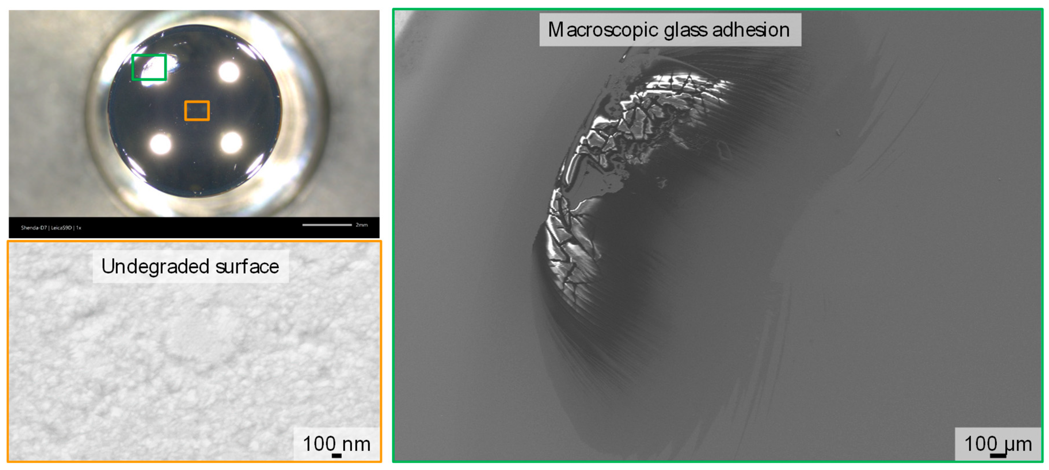
3.3. Degraded Coated Surfaces (DLC/PtIr/CrAlN)

Light microscope images of a DLC-coated lower molding tool from unused before molding up to 500 molding cycles are shown in Figure 5. The large bright circles represent reflections of the light source. Although no surface alterations can be observed after 10 and 50 molding cycles, first surface modification can be seen at the edge of the molding tool after 100 molding cycles. Thus, the protective coating does not fail in the center, where the longest contact time between the molding tool and the heated glass exists, but in the peripheral area, where contact is only achieved during the pressing process. During the following 400 molding cycles, the degradation in the edge area increases further. There is still no degraded surface in the center, as can be demonstrated by SEM analysis (Figure 6). The surface roughness remains less than 5 nm. Opposite to this, microscopic deposits are present at the edge of the mold. EDX measurements proved that these deposits are glass adhesions and streaks of glass components. Glass adhesions have a lateral size of a few micrometers at maximum. Overall, even in the area of glass adhesions, the DLC coating was unbroken after 500 molding cycles. There was no coating delamination to be found.
In contrast to the molds coated with DLC, the molds coated with CrAlN and PtIr already failed after a small number of molding cycles. Figure 7 shows a degraded mold coated with CrAlN after the first pressing. A macroscopic glass adhesion can be seen off-centered. The center still shows an undegraded surface. The surface bulges, which were already detectable due to the columnar layer morphology after coating, are still visible. Although the CrAlN coating showed great potential to mold chalcogenide glass at temperatures around 225 °C [18], the CrAlN coating failed early at a higher molding temperature of 540 °C. One potential explanation could be microstructural changes within the CrAlN coating, resulting in a rapid decrease in the hardness of columnar CrAlN coatings at temperatures above 400 °C [38].
For the PtIr coating, five molding cycles were carried out (Figure 8). Here, glass adhesions can be observed after five molding cycles (Figure 9). In accordance with the observations of the degradation of the DLC and CrAlN protective coatings, the damaged surface was also not observed in the center, but in the edge region. In the center, neither coating degradation nor delamination occurred. The measured surface roughness (Ra) here is still less than 5 nm. The reason for the premature failure of the PtIr coating, deposited with a thin Cr adhesion layer, could be the unstable chemical behavior of this coating system at high temperatures, which was analyzed in a previous study [39]. In this study, diffusion of Cr atoms of the Cr adhesion layer through PtIr columnar grain boundaries to the coating surface was identified as the initial degradation mechanism of this PtIr coating system. The Cr atoms subsequently oxidized at the surface. Therefore, oxidized Cr on the surface may have promoted the formation of the observed glass adhesions, whereas undamaged PtIr coating still behaves chemically inert and does not provide adhesion of glass.

3.4. FEM Analysis

Based on the reported friction coefficients for DLC and noble metal coatings in [19], a qualitative analysis by FEM simulation was conducted, where a friction coefficient of 0.1 was adopted to represent the DLC coating and that of 0.6 was adopted to represent the PtIr and CrAlN coatings. By comparing the simulation results, the relationship between the friction coefficient and the induced stress in the mold surface during the PGM process can be qualitatively obtained in an inverse manner. This comparison can assist engineers in determining whether coating defects might be caused by a high friction behavior.

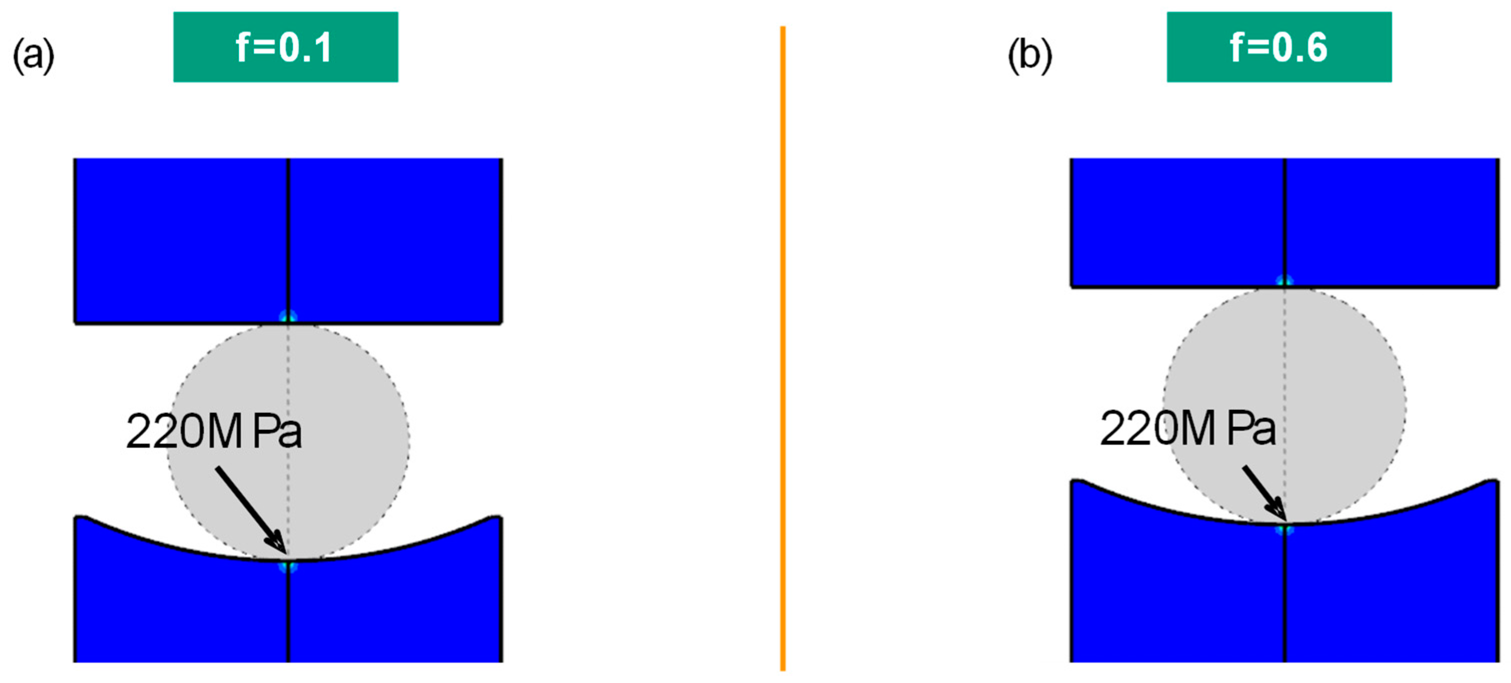
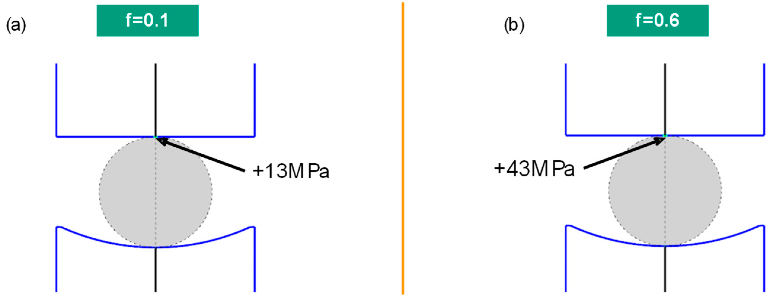
3.4.1. Stress Analysis at the First Contact between Molds and Glass

A local stress concentration appears at the first contact between the molds and glass because of the point contact. As shown in Figure 10, the Mises stress peak of about 220 MPa is at the center of the molds. This stress peak is independent of the friction coefficients due to the zero relative velocity in the center and also the same applied load.
However, a large difference in shear stress at the surface was observed at the first contact (Figure 11). At this point, the maximal shear stress appears in the center of the plan mold. The greater the friction coefficient, the greater the shear stress, which fits Coulomb’s law of friction well. A shear stress of 13 MPa was simulated for a low friction coefficient of 0.1 and a shear stress of 43 MPa for a high friction coefficient of 0.6.

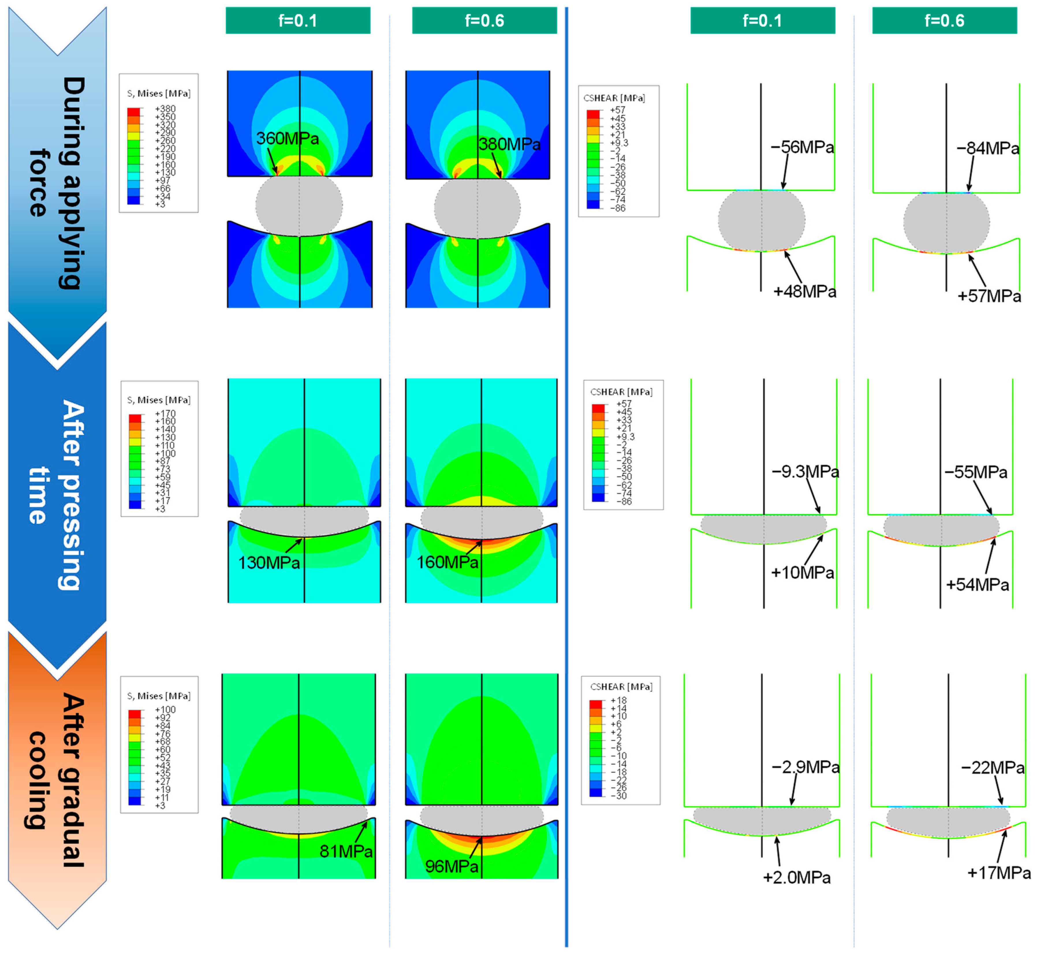
3.4.2. Stress Analysis in Molding and Gradual Cooling

In the molding and gradual cooling stage, glass and molding tools are stressed by the applied force and temperature change. Thus, stress analysis can increase understanding of the induced stresses and can potentially explain the area of coating defect formation. The Mises stress changes are shown in Figure 12 (left). During molding, the Mises stress induced in the force growth is independent of the friction coefficient, which is also observed in the situation of the first contact in Figure 10. However, this independence ends after pressing time. The higher the friction coefficient is, the larger the Mises stress is in the center area of the lower mold during the gradual cooling stage.
Not only the Mises stress, but also the shear stress is a relevant parameter for analyzing the coating defect formation. Similar to the Mises stress, the shear stress change in the molding and gradual cooling stage is shown in Figure 12 (right). Before the molding force reaches its maximum value (2 kN), the shear stress is similar between the cases with low and high friction coefficients. The fact behind this is that the lower molds move with a defined speed before the rising force reaches its maximum value. Thus, deformation rate and relative slipping speed are independent of the friction coefficient.
During the application of constant pressing force, the shear stress in the lower mold surface with a friction coefficient of 0.6 is about five times bigger (54 MPa) than that with a friction coefficient of 0.1 (10 MPa). This difference is smaller for the upper mold surface. After the gradual cooling, the absolute shear stress in the surface is reduced, but the relation between the stress and the friction coefficient remains (17 MPa for a friction coefficient of 0.6 and 2 MPa for a friction coefficient of 0.1).
Furthermore, the maximum positive and negative shear stress in the lower and upper mold is at the edge of the contact area, as shown in Figure 12 (right). This suggests that the increased mechanical stress outside the center has a high relevance to the coating failure in this region, which agrees with the observation from Figure 8. Hence, the largely different lifecycles of the DLC and the PtIr coatings, as well as the location of the observed coating degradation, can be explained by the simulation analysis above.

4. Conclusions

The lifetime and degradation mechanisms of three different protective coatings—DLC, CrAlN and PtIr—were evaluated by molding S-FPM3 glass in a commercial precision glass molding machine. The following conclusions can be drawn:
Compared to the other coating systems studied in this work, DLC coating shows the best resistance to degradation. After 500 molding cycles, only isolated local micro defects, primarily micro glass adhesions and streaks, were observed in the DLC coating. In contrast, CrAlN and PtIr coating failed after only a few molding cycles, whereby macroscopic glass adhesions strongly restrict the lifetime of coated molding tools. For all three investigated coatings systems, coating degradation was initially observed not in the mold center, but in the outer mold surface area.
As a potential reason for this observation, stress calculation by FEM simulation identified the highest shear stress at the outer surface area on the mold during the performed glass molding process. The calculated shear stress is highly dependent on friction coefficients. Assuming a high friction coefficient (f = 0.6 assumed for CrAlN and PtIr), shear stresses of up to 55 MPa were calculated, whereas only 10 MPa were calculated for a low friction coefficient (f = 0.1 assumed for DLC).

Author Contributions

Conceptualization, C.C. and M.F.; methodology, M.F.; software, C.J.; formal analysis, M.F. and C.J.; investigation, C.C., L.-A.W. and M.-Y.D.; resources, C.C., T.G. and T.B.; data curation, L.-A.W.; writing—original draft preparation, C.C., M.F. and C.J.; writing—review and editing, T.G. and Y.-L.L.; supervision, T.G. and T.B.; project administration, C.C.; funding acquisition, Y.-L.L. All authors have read and agreed to the published version of the manuscript.

Funding

This work was supported by National Natural Science Foundation of China: 62075018 and People’s Government of Jilin Province: 20200403018SF.

Institutional Review Board Statement

Not applicable.

Informed Consent Statement

Not applicable.

Data Availability Statement

Data is unavailable due to privacy restrictions.

Conflicts of Interest

The authors declare no conflict of interest.

References

  1. Han, P.; Tseng, Y.-C.; Tsai, C.-M. Wide field of view lens design with uniform image illumination in capsule endoscope system. Microsyst. Technol. 2021, 27, 1115–1122. [Google Scholar] [CrossRef]
  2. Hoy, C.L.; Ferhanoğlu, O.; Yildirim, M.; Piyawattanametha, W.; Ra, H.; Solgaard, O.; Ben-Yakar, A. Optical design and imaging performance testing of a 9.6-mm diameter femtosecond laser microsurgery probe. Opt. Express 2011, 19, 10536–10552. [Google Scholar] [CrossRef] [PubMed]
  3. Oh, J.-G.; Lee, D.-K.; Kim, Y.-G.; Lee, K.-H.; Park, Y.-S.; Jang, K.-H.; Kang, S.-G. A study on the optical parts for a semiconductor laser module. J. Korean Phys. Soc. 2014, 65, 1536–1541. [Google Scholar] [CrossRef]
  4. Park, K.-W.; Lee, J.U. A study for stray light distribution of mobile phone camera consisting of two aspheric lenses. Korean J. Opt. Photonic 2009, 20, 6–15. [Google Scholar] [CrossRef]
  5. Zhang, L.; Liu, W. Precision glass molding: Toward an optimal fabrication of optical lenses. Front. Mech. Eng. 2017, 12, 3–17. [Google Scholar] [CrossRef]
  6. Maschmeyer, R.O.; Andrysick, C.A.; Geyer, T.W.; Meissner, H.E.; Parker, C.J.; Sanford, L.M. Precision molded-glass optics. Appl. Opt. 1983, 22, 2410–2412. [Google Scholar] [CrossRef]
  7. Yi, A.Y.; Jain, A. Compression molding of aspherical glass lenses—A combined experimental and numerical analysis. J. Am. Ceram. Soc. 2005, 88, 579–586. [Google Scholar] [CrossRef]
  8. Davis, J.R. ASM Specialty Handbook: Tool Materials; ASM International: Materials Park, OH, USA, 1995. [Google Scholar]
  9. Upadhyaya, G.S. Cemented Tungsten Carbides: Production, Properties and Testing; Noyes Publications: Westwood, NJ, USA, 1998. [Google Scholar]
  10. Guo, J. Corrective finishing of a micro-aspheric mold made of tungsten carbide to 50 nm accuracy. Appl. Opt. 2015, 54, 5764–5770. [Google Scholar] [CrossRef]
  11. Klocke, F.; Georgiadis, K.; Dambon, O.; Bouzakis, K.-D.; Gerardis, S.; Skordaris, G. A complete qualification methodology for coatings of precision glass molding tools. Proc. SPIE Opt. Manuf. Test. 2011, 9, 81260. [Google Scholar] [CrossRef]
  12. Ma, K.J.; Chien, H.H.; Chuan, W.H.; Chao, C.L.; Hwang, K.C. Design of protective coatings for glass lens molding. Key Eng. Mater. 2008, 364–366, 655–661. [Google Scholar] [CrossRef]
  13. Akhtar, A.; Ruan, H. Review on thin film coatings for precision glass molding. Surf. Interfaces 2022, 30, 101903. [Google Scholar] [CrossRef]
  14. Klocke, F.; Dambon, O.; Rohwerder, M.; Bernhardt, F.; Friedrichs, M.; Merzlikin, S.V. Model of coating wear degradation in precision glass molding. Int. J. Adv. Manuf. Technol. 2016, 87, 43–49. [Google Scholar] [CrossRef]
  15. Li, K.; Xu, G.; Huang, X.; Chen, Q.; Xie, Z.; Gong, F. Surface evolution analysis of CrxWyNz coatings on WC mold in glass molding process. Surf. Coat. Technol. 2020, 393, 125839. [Google Scholar] [CrossRef]
  16. Brand, J.; Gadow, R.; Killinger, A. Application of diamond-like carbon coatings on steel tools in the production of precision glass components. Surf. Coat. Technol. 2004, 180–181, 213–217. [Google Scholar] [CrossRef]
  17. Klocke, F.; Bouzakis, K.-D.; Georgiadis, K.; Gerardis, S.; Skordaris, G.; Pappa, M. Adhesive interlayers’ effect on the entire structure strength of glass molding tools’ Pt–Ir coatings by nano-tests determined. Surf. Coat. Technol. 2011, 206, 1867–1872. [Google Scholar] [CrossRef]
  18. Friedrichs, M.; Grunwald, T.; Bergs, T. Evaluation of mold materials for precision glass molding. Proc. Precis. Opt. Manuf. 2018, 11171, 111710B. [Google Scholar] [CrossRef]
  19. Lee, W.-Y.; Choi, J.-H. Application of Ta-C Coating on WC Mold to Molded Glass Lens. Tribol. Lubr. 2019, 35, 106–113. [Google Scholar] [CrossRef]
  20. Bernhardt, F.; Georgiadis, K.; Dolle, L.; Dambon, O.; Klocke, F. Development of a ta-C diamond-like carbon (DLC) coating by magnetron sputtering for use in precision glass molding. Mater. Werkst. 2013, 44, 661–666. [Google Scholar] [CrossRef]
  21. Robertson, J. Diamond-Like Amorphous Carbon. Mater. Sci. Eng. R. Rep. 2002, 37, 129–281. [Google Scholar] [CrossRef]
  22. Zhang, Y.; Yan, G.; You, K.; Fang, F. Study on α-Al2O3 anti-adhesion coating for molds in precision glass molding. Surf. Coat. Technol. 2020, 391, 125720. [Google Scholar] [CrossRef]
  23. Śliwa, A.; Mikuła, J.; Gołombek, K.; Tański, T.; Kwaśny, W.; Bonek, M.; Brytan, Z. Prediction of the properties of PVD/CVD coatings with the use of FEM analysis. Appl. Surf. Sci. 2016, 388, 281–287. [Google Scholar] [CrossRef]
  24. Wen, Z.; Zhang, X.; Yue, X.; Wang, X.; Zhang, C.; Yue, Z. FEM analysis of the stress response and failure mechanism of SiC-coated Cf/SiC composites during thermal shock. Ceram. Int. 2021, 47, 21996–22005. [Google Scholar] [CrossRef]
  25. Liu, G.; Vu, A.; Dambon, O.; Klocke, F. Glass Material Modeling and its Molding Behavior. MRS Adv. 2017, 2, 875–885. [Google Scholar] [CrossRef]
  26. Jankowiak, T.; Rusinek, A.; List, G.; Sutter, G.; Abed, F. Numerical analysis for optimizing the determination of dynamic friction coefficient. Trib. Inter. 2016, 95, 86–94. [Google Scholar] [CrossRef]
  27. Li, K.; Xu, G.; Wen, X.; Zhou, J.; Gong, F. High-temperature friction behavior of amorphous carbon coating in glass molding process. Friction 2021, 9, 1648–1659. [Google Scholar] [CrossRef]
  28. Bazrafshan, M.; de Rooij, M.B.; Schipper, D.J. The effect of adhesion and roughness on friction hysteresis loops. Int. J. Mech. Sci. 2019, 155, 9–18. [Google Scholar] [CrossRef]
  29. Tsai, K.M.; Hsieh, C.Y.; Lu, H.H. Sintering of binderless tungsten carbide. Ceram. Int. 2010, 36, 689–692. [Google Scholar] [CrossRef]
  30. Yin, L.; Spowage, A.C.; Ramesh, K.; Huang, H.; Pickering, J.P.; Vancoille, E.Y.J. Influence of microstructure on ultraprecision grinding of cemented carbides. Int. J. Mach. Tools Manuf. 2004, 44, 533–543. [Google Scholar] [CrossRef]
  31. Friedrichs, M.; Peng, Z.; Grunwald, T.; Rohwerder, M.; Gault, B.; Bergs, T. PtIr protective coating system for precision glass molding tools: Design, evaluation and mechanism of degradation. Surf. Coat. Technol. 2020, 385, 125378. [Google Scholar] [CrossRef]
  32. NJS Co., Ltd. SPS Center. Available online: http://www.njs-japan.co.jp/e_carbide.html (accessed on 9 June 2023).
  33. OHARA GmbH, S-FPM3_English_.pdf. Available online: https://www.ohara-gmbh.com/fileadmin/user_upload/export-data/pdf/product_datasheets/S-FPM3_English_.pdf (accessed on 9 June 2023).
  34. Teixeira, V. Residual stress and cracking in thin PVD coatings. Vacuum 2002, 64, 393–399. [Google Scholar] [CrossRef]
  35. Yang, J.; Odén, M.; Johansson-Jõesaar, M.P.; Llanes, L. Grinding Effects on Surface Integrity and Mechanical Strength of WC-Co emented Carbides. Procedia CIRP 2014, 13, 257–263. [Google Scholar] [CrossRef]
  36. Guo, B.; Zhao, Q. Wheel normal grinding of hard and brittle materials. Int. J. Adv. Manuf. Technol. 2015, 79, 873–880. [Google Scholar] [CrossRef]
  37. Dirks, A.G.; Wolters, R.A.M.; De Veirman, A.E.M. Columnar microstructures in magnetron-sputtered refractory metal thin films of tungsten, molybdenum and W-Ti-(N). Thin Solid Film. 1992, 208, 181–188. [Google Scholar] [CrossRef]
  38. Drnovšek, A.; Vo, H.T.; Figueiredo, M.R.; Kolozsvári, S.; Hosemann, P.; Franz, F. High temperature fracture toughness of single-layer CrAlN and CrAlSiN hard coatings. Surf. Coat. Technol. 2021, 409, 126909. [Google Scholar] [CrossRef]
  39. Peng, Z.; Rohwerder, M.; Choi, P.-P.; Gault, B.; Meiners, T.; Friedrichs, M.; Kreilkamp, H.; Klocke, F.; Raabe, D. Atomic diffusion induced degradation in bimetallic layer coated cemented tungsten carbide. Corros. Sci. 2017, 120, 1–13. [Google Scholar] [CrossRef]
Figure 1. Simplified molding tools drawings: (a) upper mold and (b) lower mold.
Coatings 13 01438 g001
Figure 2. Schematic process diagram of performed coating tests.
Coatings 13 01438 g002
Figure 3. FEM simulation model.
Coatings 13 01438 g003
Figure 4. SEM images and surface roughness of molding tools: (a) uncoated, (b) DLC coated, (c) PtIr coated, (d) CrAlN coated.
Coatings 13 01438 g004
Figure 5. Surface change of DLC-coated molding tool.
Coatings 13 01438 g005
Figure 6. SEM analysis of degraded DLC coating after 500 molding cycles.
Coatings 13 01438 g006
Figure 7. SEM analysis of degraded CrAlN coating after one molding cycle.
Coatings 13 01438 g007
Figure 8. Surface change of PtIr-coated molding tool after coating, after one molding cycle and after five molding cycles.
Coatings 13 01438 g008
Figure 9. SEM analysis of degraded PtIr coating after five molding cycles.
Coatings 13 01438 g009
Figure 10. Mises stress at the first contact: (a) for a friction coefficient of 0.1 and (b) for a friction coefficient of 0.6.
Coatings 13 01438 g010
Figure 11. Shear stress at the first contact: (a) for a friction coefficient of 0.1 and (b) for a friction coefficient of 0.6.
Coatings 13 01438 g011
Figure 12. Mises stress change (left) and shear stress change (right) in the molds in the molding and gradual cooling stage (glass is the gray part).
Coatings 13 01438 g012
Table 1. WC100 Characteristic table [32].
MaterialGranularity
(µm)
Density (g/cm3)Hardness (HV)Flexural Strength (MPa)Compressive Strength
(MPa)
Fracture Toughness KIC (MPa m0.5)Coefficient of Thermal Expansion (10−6 K−1)
400 °C600 °C800 °C
WC100<0.0815.62700147081205.64.84.95.1
Disclaimer/Publisher’s Note: The statements, opinions and data contained in all publications are solely those of the individual author(s) and contributor(s) and not of MDPI and/or the editor(s). MDPI and/or the editor(s) disclaim responsibility for any injury to people or property resulting from any ideas, methods, instructions or products referred to in the content.

