
Effects of Synchronous Bias Mode and Duty Cycle on Microstructure and Mechanical Properties of AlTiN Coatings Deposited via HiPIMS


Abstract
:1. Introduction
2. Experiment Details
3. Results and Discussion
4. Conclusions
Author Contributions
Funding
Institutional Review Board Statement
Informed Consent Statement
Data Availability Statement
Acknowledgments
Conflicts of Interest
References
- Velicu, I.-L.; Tiron, V.; Porosnicu, C.; Burducea, I.; Lupu, N.; Stoian, G.; Popa, G.; Munteanu, D. Enhanced properties of tungsten thin films deposited with a novel HiPIMS approach. Appl. Surf. Sci. 2017, 424, 397–406. [Google Scholar] [CrossRef]
- Kumar, A.; Bauri, R.; Naskar, A.; Chattopadhyay, A. Characterization of HiPIMS and DCMS deposited TiAlN coatings and machining performance evaluation in high speed dry machining of low and high carbon steel. Surf. Coat. Technol. 2021, 417, 127180. [Google Scholar] [CrossRef]
- Kouznetsov, V.; Macak, K.; Schneider, J.M.; Helmersson, U.; Petrov, I. A novel pulsed magnetron sputter technique utilizing very high target power densities. Surf. Coat. Technol. 1999, 122, 290–293. [Google Scholar] [CrossRef]
- Ehiasarian, A.; New, R.; Münz, W.-D.; Hultman, L.; Helmersson, U.; Kouznetsov, V. Influence of high power densities on the composition of pulsed magnetron plasmas. Vacuum 2002, 65, 147–154. [Google Scholar] [CrossRef]
- Chang, C.-L.; Huang, C.-H.; Lin, C.-Y.; Yang, F.-C.; Tang, J.-F. Mechanical properties of amorphous and crystalline CrN/CrAlSiN multilayer coating fabricated using HPPMS. Surf. Interfaces 2022, 31, 102064. [Google Scholar] [CrossRef]
- Chang, C.-L.; Luo, G.-J.; Yang, F.-C.; Tang, J.-F. Effects of duty cycle on microstructure of TiN coatings prepared using CAE/HiPIMS. Vacuum 2021, 192, 110449. [Google Scholar] [CrossRef]
- Sarakinos, K.; Alami, J.; Konstantinidis, S. High power pulsed magnetron sputtering: A review on scientific and engineering state of the art. Surf. Coat. Technol. 2010, 204, 1661–1684. [Google Scholar] [CrossRef]
- Gui, B.; Zhou, H.; Zheng, J.; Liu, X.; Feng, X.; Zhang, Y.; Yang, L. Microstructure and properties of TiAlCrN ceramic coatings deposited by hybrid HiPIMS/DC magnetron co-sputtering. Ceram. Int. 2021, 47, 8175–8183. [Google Scholar] [CrossRef]
- Alhafian, M.; Chemin, J.; Fleming, Y.; Bourgeois, L.; Penoy, M.; Useldinger, R.; Soldera, F.; Mücklich, F. Choquet. Comparison on the structural, mechanical and tribological properties of TiAlN coatings deposited by HiPIMS and Cathodic Arc Evaporation. Surf. Coat. Technol. 2021, 423, 127529. [Google Scholar] [CrossRef]
- Alami, J.; Maric, Z.; Busch, H.; Klein, F.; Grabowy, U.; Kopnarski, M.J.S. Enhanced ionization sputtering: A concept for superior industrial coatings. Surf. Coat. Technol. 2014, 255, 43–51. [Google Scholar] [CrossRef]
- Anders, A.J.S. Discharge physics of high power impulse magnetron sputtering. Surf. Coat. Technol. 2011, 205, S1–S9. [Google Scholar] [CrossRef]
- Bernátová, K.; Fekete, M.; Klein, P.; Hnilica, J.; Vašina, P.J.P.S.S. Ionisation fractions of sputtered titanium species at target and substrate region in HiPIMS. Plasma Sources Sci. Technol. 2020, 29, 055010. [Google Scholar] [CrossRef]
- Drábik, M.; Truchlý, M.; Ballo, V.; Roch, T.; Kvetková, L.; Kúš, P. Influence of substrate material and its plasma pretreatment on adhesion and properties of WC/aC: H nanocomposite coatings deposited at low temperature. Surf. Coat. Technol. 2018, 333, 138–147. [Google Scholar] [CrossRef]
- Zhao, M.-J.; Huang, J.; Zhang, J.-F.; Hsu, C.-H.; Wu, W.-Y.; Huang, P.-H.; Wei, S.-F.; Lien, S.-Y.; Zhu, W.-Z. Effect of oxygen flow rate ratio on crystalline phase and properties of copper oxide films prepared by room-temperature high-power impulse magnetron sputtering. Surf. Coat. Technol. 2022, 434, 128215. [Google Scholar] [CrossRef]
- Hsu, Y.-H.; Liu, H.-W.; Lien, S.-Y.; Wu, W.-Y. High-power impulse magnetron sputter deposition for enhanced optical transmittance and electrical conductivity of flexible coating. Thin Solid Film. 2022, 748, 139158. [Google Scholar] [CrossRef]
- Zhao, M.-J.; Chen, Z.-Z.; Shi, C.-Y.; Chen, Q.-Z.; Xu, M.; Wu, W.-Y.; Wuu, D.-S.; Lien, S.-Y.; Zhu, W.-Z.J.V. Modulation of carrier density in indium–gallium–zinc-oxide thin film prepared by high-power impulse magnetron sputtering. Vacuum 2023, 207, 111640. [Google Scholar] [CrossRef]
- Claver, A.; Randulfe, J.J.; Palacio, J.F.; de Ara, J.F.; Almandoz, E.; Montalá, F.; Colominas, C.; Cot, V.; García, J.A. Improved adhesion and tribological properties of AlTiN-TiSiN coatings deposited by DCMS and HiPIMS on nitrided tool steels. Coatings 2021, 11, 1175. [Google Scholar] [CrossRef]
- Singh, A.; Ghosh, S.; Aravindan, S. Flank wear and rake wear studies for arc enhanced HiPIMS coated AlTiN tools during high speed machining of nickel-based superalloy. Surf. Coat. Technol. 2020, 381, 125190. [Google Scholar] [CrossRef]
- Zhao, J.; Liu, Z. Influences of coating thickness on cutting temperature for dry hard turning Inconel 718 with PVD TiAlN coated carbide tools in initial tool wear stage. J. Manuf. Process. 2020, 56, 1155–1165. [Google Scholar] [CrossRef]
- Kuang, S.; Wang, J.; Wang, L.; Huang, W.; Zhou, Z. Improvement of the mechanical and the tribological properties of CrNbTiMoZr coatings through the incorporation of carbon and the adjustment of the substrate bias voltage. Surf. Coat. Technol. 2021, 412, 127064. [Google Scholar] [CrossRef]
- Fan, Q.; Zhang, S.; Ma, D.; Wu, Z.; Cao, F.; Liu, Y.; Wang, T. Bias voltage optimization and cutting performance of AlCrN coatings deposited by a hybrid technology. Vacuum 2022, 204, 111348. [Google Scholar] [CrossRef]
- Wei, H.; Xia, J.; Zhou, W.; Zhou, L.; Hussain, G.; Li, Q.; Ostrikov, K.K. Adhesion and cohesion of epoxy-based industrial composite coatings. Compos. Part B Eng. 2020, 193, 108035. [Google Scholar] [CrossRef]
- Hsu, T.-W.; Greczynski, G.; Boyd, R.; Kolozsvári, S.; Polcik, P.; Bolz, S.; Bakhit, B.; Odén, M. Influence of Si content on phase stability and mechanical properties of TiAlSiN films grown by AlSi-HiPIMS/Ti-DCMS co-sputtering. Surf. Coat. Technol. 2021, 427, 127661. [Google Scholar] [CrossRef]
- Das, C.R.; Rangwala, M.; Ghosh, A. Influence of substrate bias voltage on microstructure and mechanical characteristics of TiAlSiN coating deposited by High Power Impulse Magnetron Sputtering (HiPIMS). Surf. Coat. Technol. 2023, 458, 129351. [Google Scholar] [CrossRef]
- Bohlmark, J.; Lattemann, M.; Gudmundsson, J.; Ehiasarian, A.; Gonzalvo, Y.A.; Brenning, N.; Helmersson, U. The ion energy distributions and ion flux composition from a high power impulse magnetron sputtering discharge. Thin Solid Film. 2006, 515, 1522–1526. [Google Scholar] [CrossRef]
- Greczynski, G.; Lu, J.; Jensen, J.; Petrov, I.; Greene, J.E.; Bolz, S.; Kölker, W.; Schiffers, C.; Lemmer, O.; Hultman, L. Metal versus rare-gas ion irradiation during Ti1− x Al x N film growth by hybrid high power pulsed magnetron/dc magnetron co-sputtering using synchronized pulsed substrate bias. J. Vac. Sci. Technol. A Vac. Surf. Film. 2012, 30, 061504. [Google Scholar] [CrossRef]
- Cemin, F.; Abadias, G.; Minea, T.; Lundin, D. Tuning high power impulse magnetron sputtering discharge and substrate bias conditions to reduce the intrinsic stress of TiN thin films. Thin Solid Film. 2019, 688, 137335. [Google Scholar] [CrossRef]
- Zhang, Q.; Wu, Z.; Xu, Y.X.; Wang, Q.; Chen, L.; Kim, K.H.J.S. Improving the mechanical and anti-wear properties of AlTiN coatings by the hybrid arc and sputtering deposition. Surf. Coat. Technol. 2019, 378, 125022. [Google Scholar] [CrossRef]
- Beake, B.; Smith, J.; Gray, A.; Fox-Rabinovich, G.; Veldhuis, S.; Endrino, J.J.S. Investigating the correlation between nano-impact fracture resistance and hardness/modulus ratio from nanoindentation at 25–500° C and the fracture resistance and lifetime of cutting tools with Ti1− xAlxN (x= 0.5 and 0.67) PVD coatings in milling operations. Surf. Coat. Technol. 2007, 201, 4585–4593. [Google Scholar]
- Li, B.; Xu, Y.; Rao, G.; Wang, Q.; Zheng, J.; Zhu, R.; Chen, Y.J.C. Tribological properties and cutting performance of AlTiN coatings with various geometric structures. Coatings 2023, 13, 402. [Google Scholar] [CrossRef]
- Tang, J.-F.; Huang, S.-Y.; Lin, J.-H.; Yang, F.-C.; Chang, C.-L. Mechanical properties of TiN deposited in synchronous bias mode through high-power impulse magnetron sputtering. Surf. Coat. Technol. 2022, 434, 128201. [Google Scholar] [CrossRef]
- Vavassori, D.; Mirani, F.; Gatti, F.; Dellasega, D.; Passoni, M. Role of magnetic field and bias configuration on HiPIMS deposition of W films. Surf. Coat. Technol. 2023, 458, 129343. [Google Scholar] [CrossRef]
- Greczynski, G.; Lu, J.; Jensen, J.; Bolz, S.; Kölker, W.; Schiffers, C.; Lemmer, O.; Greene, J.E.; Hultman, L. A review of metal-ion-flux-controlled growth of metastable TiAlN by HIPIMS/DCMS co-sputtering. Surf. Coat. Technol. 2014, 257, 15–25. [Google Scholar] [CrossRef]
- Salamania, J.; Johnson, L.; Schramm, I.; Calamba, K.; Boyd, R.; Bakhit, B.; Rogström, L.; Odén, M. Influence of pulsed-substrate bias duty cycle on the microstructure and defects of cathodic arc-deposited Ti1-xAlxN coatings. Surf. Coat. Technol. 2021, 419, 127295. [Google Scholar] [CrossRef]
- Tuilier, M.-H.; Pac, M.-J.; Covarel, G.; Rousselot, C.; Khouchaf, L. Structural investigation of thin films of Ti1− xAlxN ternary nitrides using Ti K-edge X-ray absorption fine structure. Surf. Coat. Technol. 2007, 201, 4536–4541. [Google Scholar] [CrossRef]
- Chen, L.; Paulitsch, J.; Du, Y.; Mayrhofer, P.H. Thermal stability and oxidation resistance of Ti–Al–N coatings. Surf. Coat. Technol. 2012, 206, 2954–2960. [Google Scholar] [CrossRef]
- Mendez, A.; Monclus, M.; Santiago, J.; Fernández-Martínez, I.; Rojas, T.C.; Garcia-Molleja, J.; Avella, M.; Dams, N.; Panizo-Laiz, M.; Molina-Aldareguia, J.M. Effect of Al content on the hardness and thermal stability study of AlTiN and AlTiBN coatings deposited by HiPIMS. Surf. Coat. Technol. 2021, 422, 127513. [Google Scholar] [CrossRef]
- Kimura, A.; Hasegawa, H.; Yamada, K.; Suzuki, T. Metastable Ti1-xAlxN films with different Al content. J. Mater. Sci. Lett. 2000, 19, 601–602. [Google Scholar] [CrossRef]
- Pelleg, J.; Zevin, L.; Lungo, S.; Croitoru, N.J.T.S.F. Reactive-sputter-deposited TiN films on glass substrates. Thin Solid Film. 1991, 197, 117–128. [Google Scholar] [CrossRef]
- Zhang, Z.; Zhang, L.; Yan, W.; Zhang, Y.; Yuan, H.; Shen, Y.; Liao, B.; Zhang, X.; Zhang, F.; Ouyang, X.J.M.C. Effect of self-ion with high-energy irradiation on the surface morphology, microstructure and mechanical properties of nanocrystalline TiAlN coating. Materials 2022, 190, 112041. [Google Scholar] [CrossRef]
- Xu, Y.; Li, G.; Li, G.; Gao, F.; Xia, Y.J.A.S.S. Effect of bias voltage on the growth of super-hard (AlCrTiVZr) N high-entropy alloy nitride films synthesized by high power impulse magnetron sputtering. Appl. Surf. Sci. 2021, 564, 150417. [Google Scholar] [CrossRef]
- Lesuer, D.; Syn, C.; Sherby, O. Nano-subgrain strengthening in ball-milled iron. Mater. Sci. Eng. A 2007, 463, 54–60. [Google Scholar] [CrossRef]
- Xian, G.; Xiong, J.; Fan, H.; Guo, Z.; Xian, L.; Sun, L.; Zhao, H.J.T.S.F. Effect of substrate pretreatments on the structure and properties of AlTiN coatings deposited on TiCN-based cermets. Thin Solid Film. 2023, 770, 139769. [Google Scholar] [CrossRef]
- Zhang, H.; Mei, F.; Yu, Y.; Lin, X.; Gao, J.J.S. Improvement on the mechanical, tribological properties and cutting performance of AlTiN-based coatings by compositional and structural design. Surf. Coat. Technol. 2021, 422, 127503. [Google Scholar] [CrossRef]
- Pang, X.; Yang, H.; Gao, K.; Wang, Y.; Volinsky, A.A.J.T.S.F. AlTiN layer effect on mechanical properties of Ti-doped diamond-like carbon composite coatings. Thin Solid Film. 2011, 519, 5353–5357. [Google Scholar] [CrossRef]
- Yang, F.-C.; Lin, C.-Y.; Tang, J.-F.; Chang, C.-L.J.S. Effect of mid-frequency pulse insertion on the microstructural and mechanical properties of AlTiN coatings prepared using superimposed HiPIMS process. Surf. Coat. Technol. 2020, 388, 125597. [Google Scholar] [CrossRef]
- Warcholinski, B.; Gilewicz, A.; Kuprin, A.; Tolmachova, G.; Ovcharenko, V.; Kuznetsova, T.; Zubar, T.; Khudoley, A.; Chizhik, S.J.V. Mechanical properties of Cr-ON coatings deposited by cathodic arc evaporation. Vacuum 2018, 156, 97–107. [Google Scholar] [CrossRef]
- Özkan, D.; Yılmaz, M.A.; Erdem, C.; Türküz, C.; Sulukan, E.; Yağcı, M.B.J.C.I. Wear and friction behavior of CrTiN/TiCN and CrTiN/CrCN multilayer composite coatings. Ceram. Int. 2022, 48, 13732–13747. [Google Scholar] [CrossRef]


| Parameters | Values | |||
|---|---|---|---|---|
| Target to substrate distance (mm) | 150 | |||
| Working pressure (Pa) | 0.4 | |||
| Chamber temperature (°C) | 65 | |||
| N2/Ar flow ratio (%) | 33 | |||
| Deposition time of AlTiN (min) | 126 | |||
| HiPIMS of duty cycle (%) | 3 | |||
| Pulse frequency (Hz) | 200 | |||
| Pulse on time/off-time (μs) | 150/4850 | |||
| Bias voltage mode | DC | |||
| TD0 3% | TD0 6% | TD0 12% | TD0 18% | |
| TD50 3% | TD50 6% | TD50 12% | TD50 18% | |
| Substrate bias (V) | −45 | |||
| Sample Name | Peak Current (A) | Average Power (W/μs) |
|---|---|---|
| DC | 14.4 | 71.9 |
| TD0 3% | 14.4 | 6.9 |
| TD0 6% | 14.8 | 39.7 |
| TD0 12% | 15.6 | 60.4 |
| TD0 18% | 16.4 | 75.2 |
| TD50 3% | 16.8 | 23.6 |
| TD50 6% | 16.4 | 43.4 |
| TD50 12% | 15.6 | 59.1 |
| TD50 18% | 15.2 | 74.5 |
| Sample Name | Atomic Ratio (at.%) | Al/(Al+Ti) Ratio, x | N/(Al+Ti) Ratio | |||
|---|---|---|---|---|---|---|
| Al | Ti | N | O | |||
| DC | 35.51 | 13.72 | 49.39 | 1.39 | 0.72 | 1.00 |
| TD0 3% | 34.70 | 14.12 | 48.77 | 2.41 | 0.71 | 1.00 |
| TD0 6% | 34.76 | 14.07 | 48.93 | 2.24 | 0.71 | 1.00 |
| TD0 12% | 35.89 | 13.02 | 49.58 | 1.51 | 0.73 | 1.01 |
| TD0 18% | 36.64 | 12.55 | 49.33 | 1.48 | 0.74 | 1.00 |
| TD50 3% | 35.93 | 13.02 | 49.24 | 1.81 | 0.73 | 1.01 |
| TD50 6% | 35.45 | 13.66 | 48.74 | 2.15 | 0.72 | 1.01 |
| TD50 12% | 35.29 | 12.89 | 49.45 | 2.37 | 0.73 | 1.01 |
| TD50 18% | 35.42 | 12.76 | 49.76 | 2.06 | 0.74 | 1.03 |
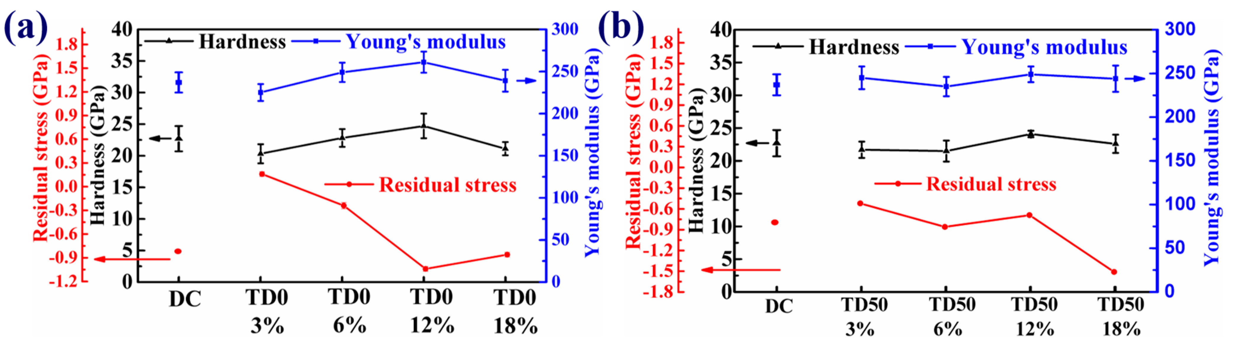
| Sample Name | Hardness (GPa) | Young’s Modulus (GPa) | H/E | H3/E2 | Residual Stress (GPa) |
|---|---|---|---|---|---|
| DC | 22.7 ± 2.0 | 237 ± 12.4 | 0.096 | 0.208 | −0.8 |
| TD0 3% | 20.3 ± 1.5 | 225 ± 10.2 | 0.090 | 0.165 | +0.2 |
| TD0 6% | 22.8 ± 1.4 | 249 ± 12.7 | 0.092 | 0.191 | −0.2 |
| TD0 12% | 24.7 ± 2.0 | 261 ± 13.5 | 0.095 | 0.221 | −1.0 |
| TD0 18% | 21.1 ± 1.2 | 239 ± 13.4 | 0.088 | 0.164 | −0.9 |
| TD50 3% | 21.7 ± 1.3 | 245 ± 13.1 | 0.088 | 0.170 | −0.5 |
| TD50 6% | 21.5 ± 1.6 | 235 ± 11.5 | 0.091 | 0.180 | −0.9 |
| TD50 12% | 24.1 ± 0.5 | 249 ± 9.8 | 0.097 | 0.226 | −0.7 |
| TD50 18% | 22.6 ± 1.4 | 244 ± 15.3 | 0.093 | 0.194 | −1.5 |
| Power | Bias | Al Ratio, x | Thickness (μm) | Hardness (GPa) | Young’s Modulus (GPa) | Residual Stress (GPa) | Reference |
|---|---|---|---|---|---|---|---|
| CAE | DC bias | 0.67 | 3.9 | ~19 | ~293 | −0.6 | [43] |
| CAE+DC | DC bias | 0.71 | 5.7 | ~19 | ~325 | −2.1 | [28] |
| CAE | DC bias | 0.62 | 3.1 | ~28 | ~315 | - | [44] |
| DC | DC bias | - | 0.4 | ~15 | ~190 | - | [45] |
| HiPIMS | P-DC bias | 0.78 | 2.8 | ~21 | ~235 | - | [37] |
| HiPIMS+MF | DC bias | 0.72 | 1.1 | ~21 | ~232 | −0.42 | [46] |
| HiPIMS | P-DC bias | 0.73 | 2.2 | ~25 | ~261 | −1.0 | This work |
Disclaimer/Publisher’s Note: The statements, opinions and data contained in all publications are solely those of the individual author(s) and contributor(s) and not of MDPI and/or the editor(s). MDPI and/or the editor(s) disclaim responsibility for any injury to people or property resulting from any ideas, methods, instructions or products referred to in the content. |
© 2023 by the authors. Licensee MDPI, Basel, Switzerland. This article is an open access article distributed under the terms and conditions of the Creative Commons Attribution (CC BY) license (https://creativecommons.org/licenses/by/4.0/).
Share and Cite
Tang, J.-F.; Huang, S.-Y.; Chen, I.-H.; Shen, G.-L.; Chang, C.-L. Effects of Synchronous Bias Mode and Duty Cycle on Microstructure and Mechanical Properties of AlTiN Coatings Deposited via HiPIMS. Coatings 2023, 13, 1512. https://doi.org/10.3390/coatings13091512
Tang J-F, Huang S-Y, Chen I-H, Shen G-L, Chang C-L. Effects of Synchronous Bias Mode and Duty Cycle on Microstructure and Mechanical Properties of AlTiN Coatings Deposited via HiPIMS. Coatings. 2023; 13(9):1512. https://doi.org/10.3390/coatings13091512
Chicago/Turabian StyleTang, Jian-Fu, Shi-Yu Huang, I-Hong Chen, Guan-Lun Shen, and Chi-Lung Chang. 2023. "Effects of Synchronous Bias Mode and Duty Cycle on Microstructure and Mechanical Properties of AlTiN Coatings Deposited via HiPIMS" Coatings 13, no. 9: 1512. https://doi.org/10.3390/coatings13091512
APA StyleTang, J.-F., Huang, S.-Y., Chen, I.-H., Shen, G.-L., & Chang, C.-L. (2023). Effects of Synchronous Bias Mode and Duty Cycle on Microstructure and Mechanical Properties of AlTiN Coatings Deposited via HiPIMS. Coatings, 13(9), 1512. https://doi.org/10.3390/coatings13091512